


Color Television Chassis
Service
Service
Service
Contents
5. Service Modes, Error Codes and Faultfinding
6. Block Diagrams and Testpoints
7. Electrical Diagrams and PWB's
B8 CHASSIS TABLE OF SCHEMATIC DIAGRAMS
MAIN CHASSIS (SECTION 1 OF 5)
MAIN CHASSIS (SECTION 2 OF 5)
MAIN CHASSIS (SECTION 3 OF 5)
MAIN CHASSIS (SECTION 4 OF 5)
MAIN CHASSIS (SECTION 5 OF 5 )
CRT PANEL (13", 19", & 20")
CRT PANEL (25" & 27")
KEYBOARD/SOUND SHAPER PANEL
STEREO PANEL SCHEMATIC
OCV TV PANEL SCHEMATIC
CARD INTERCONNECT PANEL
HEALTH CARE JACK PANEL
LODGING/SMART PORT PANEL
MAIN CHASSIS PCB (TOP)
MAIN CHASSIS PCB (BOTTOM)
13", 19", & 20" CRT PANEL PCB
25", & 27" CRT PANEL PCB
KEYBOARD/SOUND SHAPER PCB
STEREO PANEL PCB
OCV TV PANEL PCB (TOP)
OCV TV PANEL PCB (BOTTOM)
CARD INTERCONNECT PANEL PCB
HEALTH CARE JACK PANEL PCB
LODGING/SMART PORT PANEL PCB
8. Adjustments
10. Spare Parts List
B8 Series Chasssis
Manual 7562
©
Copyright 2001 Philips Consumer Electronics B.V. Eindhoven, The Netherlands.
All rights reserved. No part of this publication may be reproduced, stored in a
retrieval system or transmitted, in any form or by means, electronic, mechanical,
photographic, or otherwise without the prior permission of Philips.
Published by Philips Consumer Electronics Subject to modification 2005 Aug 24
20B8(7562)
1
3 Vp-p
50 uSec
5
4.9 Vp-p
20 uSec
2
3.2 Vp-p
20 uSec
6
50 Vp-p
5 mSec
3
1 Vp-p
20 uSec
7
800 mVp-p
5 mSec
4
5.6 Vp-p
5 mSec
8
2.7 Vp-p
5 mSec
9
400 mVp-p
5 mSec
13
2.2 Vp-p
20 uSec
10
29 Vp-p
5 mSec
14
2.2 Vp-p
20 uSec
11
1.5 Vp-p
5 mSec
15
3.5 Vp-p
20 uSec
12
2.2 Vp-p
20 uSec
16
3.6 Vp-p
5 mSec
17
450 mVp-p
5 mSec
18
750 mVp-p
5 mSec
19
5 Vp-p
20 uSec
20
4.2 Vp-p
20 uSec
20B8(7562)
21
1.2 Vp-p
20 uSec
25
1.2 Vp-p
20 uSec
22
220 mVp-p
0.5 uSec
26
1.4 Vp-p
20 uSec
23
1.2 Vp-p
20 uSec
27
2.5 Vp-p
20 uSec
24
1.2 Vp-p
20 uSec
28
1 Vp-p
20 uSec
29
1.4 Vp-p
20 uSec
33
120 Vp-p
20 uSec
30
2.5 Vp-p
20 uSec
34
1040 Vp-p(a)
20 uSec
31
2.5 Vp-p
20 uSec
35
1 Vp-p
20 uSec
32
1.6 Vp-p
20 uSec
36
1.8 Vp-p
20 uSec
37
2 Vp-p
20 uSec
38
110 Vp-p
20 uSec
39
110 Vp-p
20 uSec
40
850 mVp-p
5 mSec

20B8(7562)
41
110 Vp-p
20 uSec

B8 COLOR TV CHASSIS OVERVIEW
The B8 Series Chassis is the Statement (standard line) TV Set produced by Philips Consumer
Electronics Company for the 1997 model year. The B8 Chassis is used in TV Sets with 25, and
27 inch CRT's. The B8 Chassis is also used in Commercial TV Sets with 13, 19, 20, 25, and 27
inch CRT's. The chassis orientation is front to rear in the B8 design (sometimes called "NorthSouth"), because the chassis is longer in this direction than across. The B8 Tuning System
features 181 Channels with On-Screen Display. The main Tuning System includes the tuner
along with the Microcomputer IC and the Memory IC. The Microcomputer communicates with the
Memory IC, the Customer Keyboard, the Remote Receiver, the U/V Tuner, the TV Signal
Processor, the Stereo Decoder (optional), and the Power On/Off circuitry. The Memory IC retains
the settings for Favorite Stations, Customer Control Settings, Mode Switches, and
Service/Factory Setup Data.
The chassis features a Very Large Scale Integration (VLSI) IC for TV signal processing. This IC
performs Video IF, Sound IF, AGC control, Horizontal Signal processing, Vertical Signal
processing, Horizontal/Vertical synchronization, and Chrominance/Luminance p rocessing. The
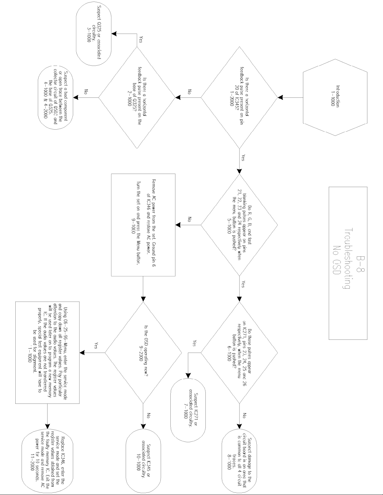
On-Screen Graphics information is placed on the main signal within the TV Signal Processor. OnScreen Graphics generation and Closed Caption decoding are processed within the
Microcomputer and the signals are sent to the TV Signal Processor. Automatic Volume Level
(AVL - called "SMART SOUND" by marketing) control from the Microcomputer is sent to the AVL
IC. The "Smart Sound" function is performed within IC720.
The B8 Chassis features a Switching Mode Power Supply for the main voltage source. A "HOT"
ground reference is used in the primary side of the power supply. A "COLD" (signal) ground from
the secondary of the power supply is used throughout the rest of the chassis. AN ISOLATION
TRANSFORMER IS REQUIRED WHEN DOING SERVICE ON ANY VERSION OF THE NEW
CHASSIS.
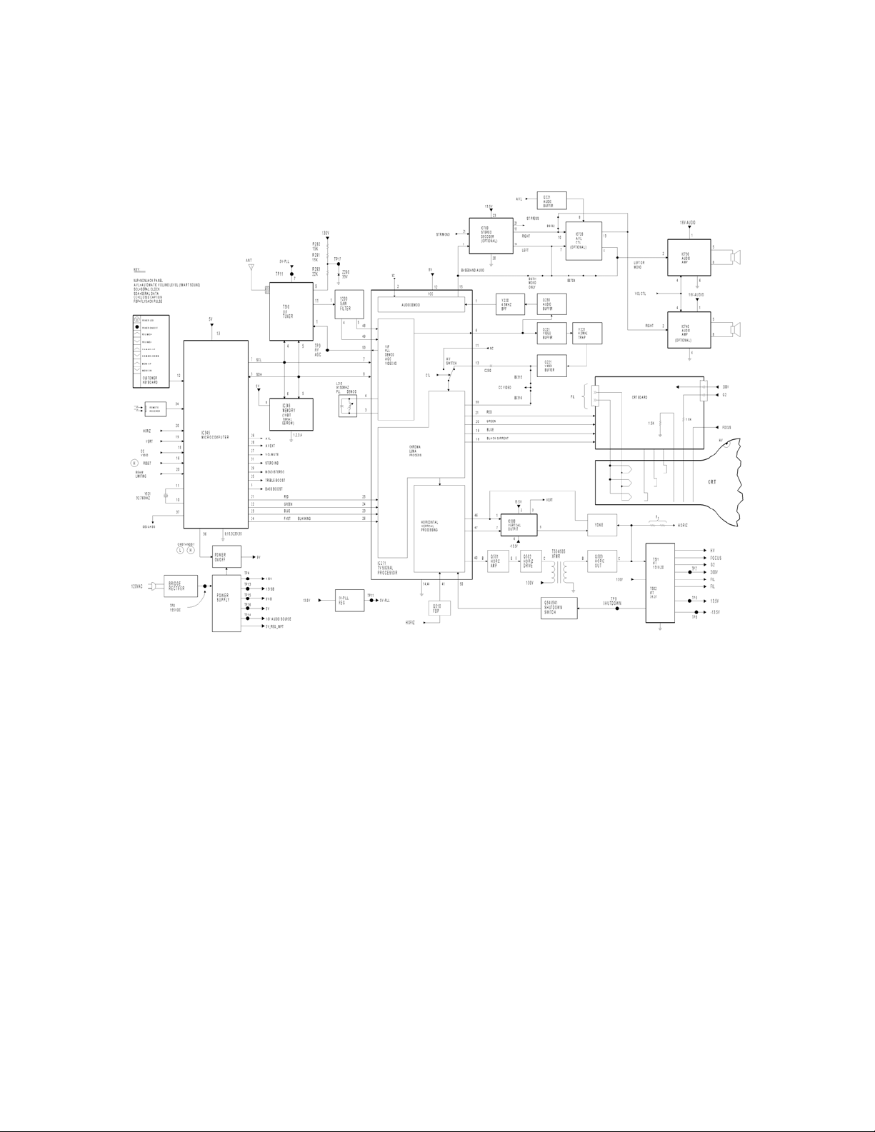
SIGNAL FLOW
The incoming TV RF signal is applied to the U/V Tuner via the Antenna RF Input. The IF signal is
developed within the U/V Tuner, then amplified by an IF Preamplifier located inside the Tuner.
The amplified IF signal is sent from Pin 11 of the U/V Tuner to the SAW Filter, Y200. The SAW
Filter produces bandpass shaping for the IF signal before it is applied to the TV Signal Processor
Integrated Circuit, IC271, for processing. AGC (to the Tuner) and AFT (to the Microcomputer)
signals are developed within IC271 and then sent to the Tuning System for RF Amp gain control.
Sound IF signal processing for the B8 Chassis is performed by coupling the 4.5MHz Sound IF
signal from IC271, Pin 6, via a Buffer Amplifier, Q221, and 4.5MHz Band Pass Filter, Y220, into
IC271, Pin 1. Audio is output from Pin 15 in mono versions and applied to the Audio Amp Output
IC, IC730, to drive the speakers. For the stereo equipped sets, the detected baseband audio
signal exits IC271, Pin 15, and then enters the Stereo Decoder IC200. The Stereo Decoder has
Internal/External switching, via the control input on Pin 21, to allow either the detected baseband
audio or External Audio from another source to be routed through and exit to IC730 and IC740.
Composite video from IC271, Pin 6, is buffered by Q221 and then passed through a 4.5MHz
Trap, Y221, to remove any sound products present. This signal is buffered again by Q225 before
it goes back to IC271, Pin 13. Depending on the part number of IC271, either BS315 or BS316
will be installed. With BS315 installed, The CC Video comes from Q225. If BS316 is installed,
the CC Video comes from Pin 38 of IC271. Internal/External switching of the video is done within
IC271. The chroma and luminance signals are then processed by the Chroma/Luminance
Process block within IC271. Sync input from the Chroma/Luminance block to the
Horizontal/Vertical Processing block is applied internally within IC271.
Brightness, Picture, Sharpness, Color, and Tint control voltages are applied to IC271 from
Microcomputer, IC300 via the IIC Bus. The Red, Green, and Blue signals are developed within
IC271 and output via Pins 21, 20, and 19. The Black Current Level Set is Output from Pin 18.
The Red, Green, and Blue video signals from IC271 are applied to the CRT Board. On the CRT
Board, these signals are amplified before being applied to the CRT. The Drive and Cutoff
controls for CRT Set-Up are controlled by the microprocessor via the IIC Bus using the Service
Test Mode.
Horizontal and Vertical signals are also developed within IC27 1. Adjustments for Horizontal
Centering, Vertical Centering, and Vertical Height are accomplished with the Remote Transmitter
via the Service Test Mode. There is no adjustment for the Horizontal Oscillator. The horizontal
circuit is a count down type of system that gets its base frequency from the 3.58MHz circuit.
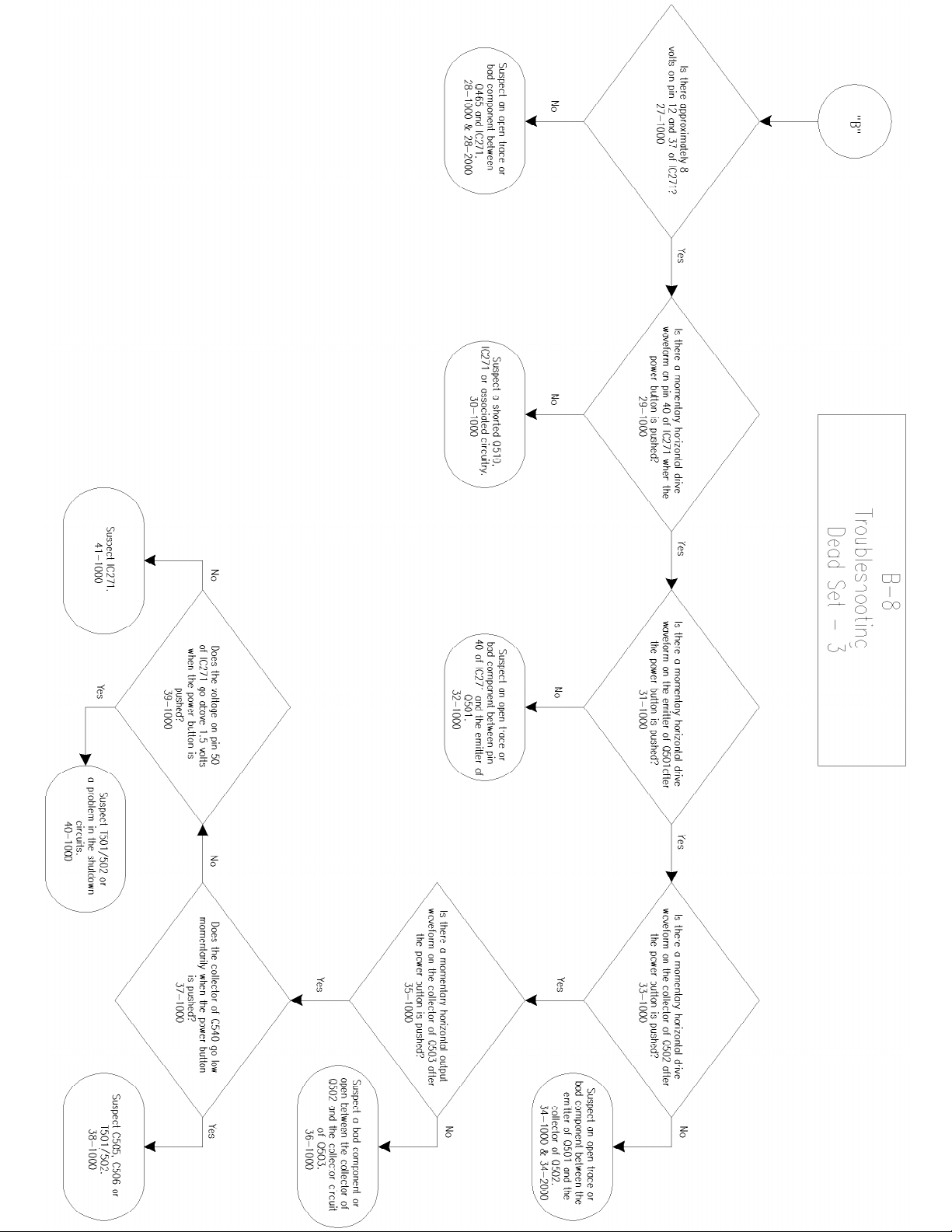
The horizontal signal is applied to a Horizontal Driver, Q502, where the signal is amplified and
transformer coupled to the Horizontal Output transistor, Q503. The output from Q503 drives the
Integrated Flyback Transformer. The IFT develops the High Voltage, Screen Voltage, Focus
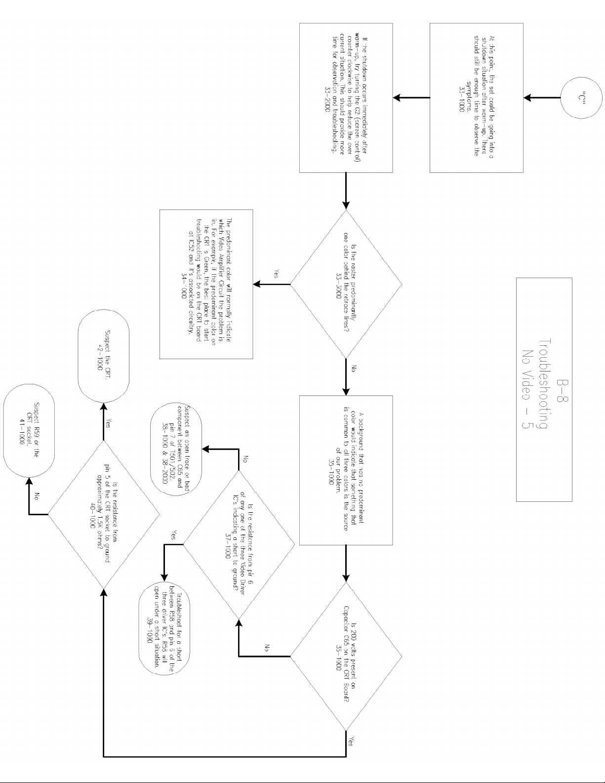
Voltage, and Filament Voltage for the Picture Tube. If the voltage in T501 (T502 for 25 and 27
inch sets) goes high, a sample is sent to Q540 and Q541, the shutdown switch. This will enable
lowering the High Voltage when it starts to elevate. Scan derived voltages provided by the IFT for
use by the chassis are the 200V, +1 3.5V, and -13.5V Sources. A horizontal pulse is also made
available for the chassis from the output circuit of the Horizontal Output transistor.
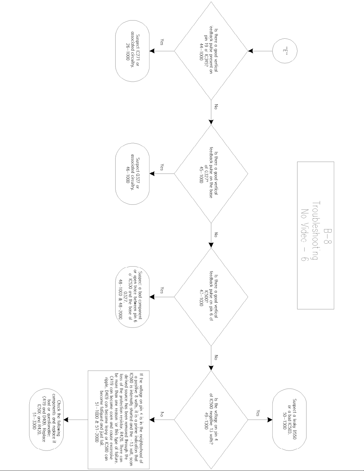
The Vertical signal exits TC271 at Pin 7 and is applied to the Vertical Output Integrated Circuit,
IC550. The vertical signal is output from IC550 and applied to the Vertical Yoke. Vertical
Centering and Vertical Height adjustments are performed via the Service Test Mode and Rem ote
Transmitter. Vertical feedback is returned to IC550, Pin 1.
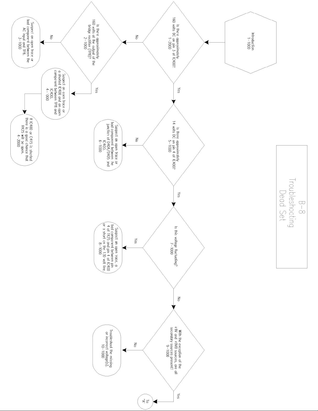
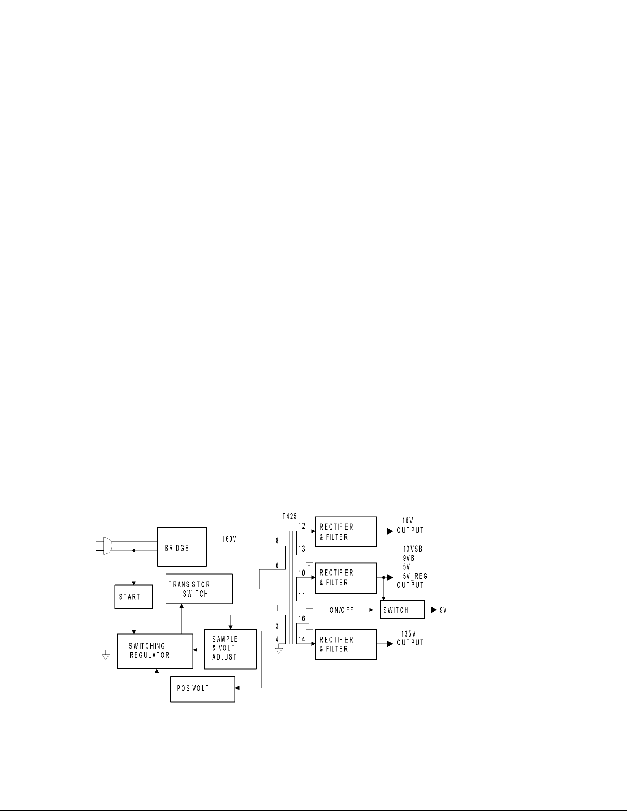
B8 CHASSIS POWER SUPPLY BLOCK
When a 120Vac Source is connected to the B8 Chassis, approximately I60Vdc is developed by

the Bridge Rectifier circuit. The 160 volts dc goes through T425 to the transistor switch. The
start up signal is taken from the neutral leg of the input ac line.
The Power Supply consists of a single integrated circuit operating as a Free-Running Switching
Mode Power Supply. The frequency of operation varies with the circuit load. There is no
separate power supply for standby. The Power Supply turns On when AC is applied. The
Switching Regulator IC starts switching when the initial voltage is applied through the Start circuit.
The Switching Regulator and the Drive circuits turns the Switch On and Off to allow current flow
through the primary of transformer T425. Energy stored in the primary during the On-time is
delivered to the secondaries during the Off-time. Feedback from the Hot seco ndary is used to
control the Switching Regulator. Positive Voltage from the hot secondary is used as B+ for the
Switching Regulator.
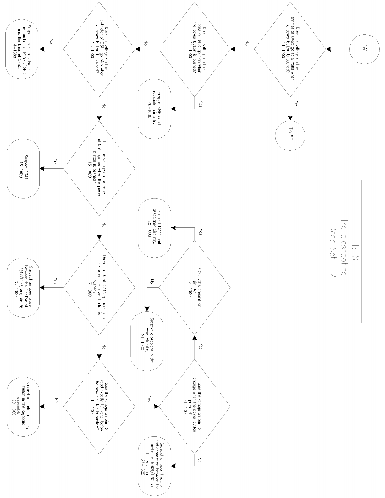
From the secondaries of T425, the voltages needed to operate the television are developed. The
Plus 9 volt output is switched for On/Off control.

All Models (7562) - MAIN CHASSIS (SECTION 1 OF 5)

All Models (7562) - MAIN CHASSIS (SECTION 2 OF 5)

All Models (7562) - MAIN CHASSIS (SECTION 3 OF 5)

All Models (7562) - MAIN CHASSIS (SECTION 4 OF 5)

All Models (7562) - MAIN CHASSIS (SECTION 5 OF 5 )

All Models (7562) - CRT PANEL (13", 19", & 20")

All Models (7562) - CRT PANEL (25" & 27")

All Models (7562) - KEYBOARD/SOUND SHAPER PANEL

All Models (7562) - STEREO PANEL SCHEMATIC

All Models (7562) - OCV TV PANEL SCHEMATIC

All Models (7562) - CARD INTERCONNECT PANEL

All Models (7562) - HEALTH CARE JACK PANEL

All Models (7562) - LODGING/SMART PORT PANEL

All Models (7562) - MAIN CHASSIS PCB (TOP)

All Models (7562) - MAIN CHASSIS PCB (BOTTOM)

All Models (7562) - 13", 19", & 20" CRT PANEL PCB

All Models (7562) - 25", & 27" CRT PANEL PCB

All Models (7562) - KEYBOARD/SOUND SHAPER PCB

All Models (7562) - STEREO PANEL PCB

All Models (7562) - OCV TV PANEL PCB (TOP)

All Models (7562) - OCV TV PANEL PCB (BOTTOM)

All Models (7562) - CARD INTERCONNECT PANEL PCB

All Models (7562) - HEALTH CARE JACK PANEL PCB
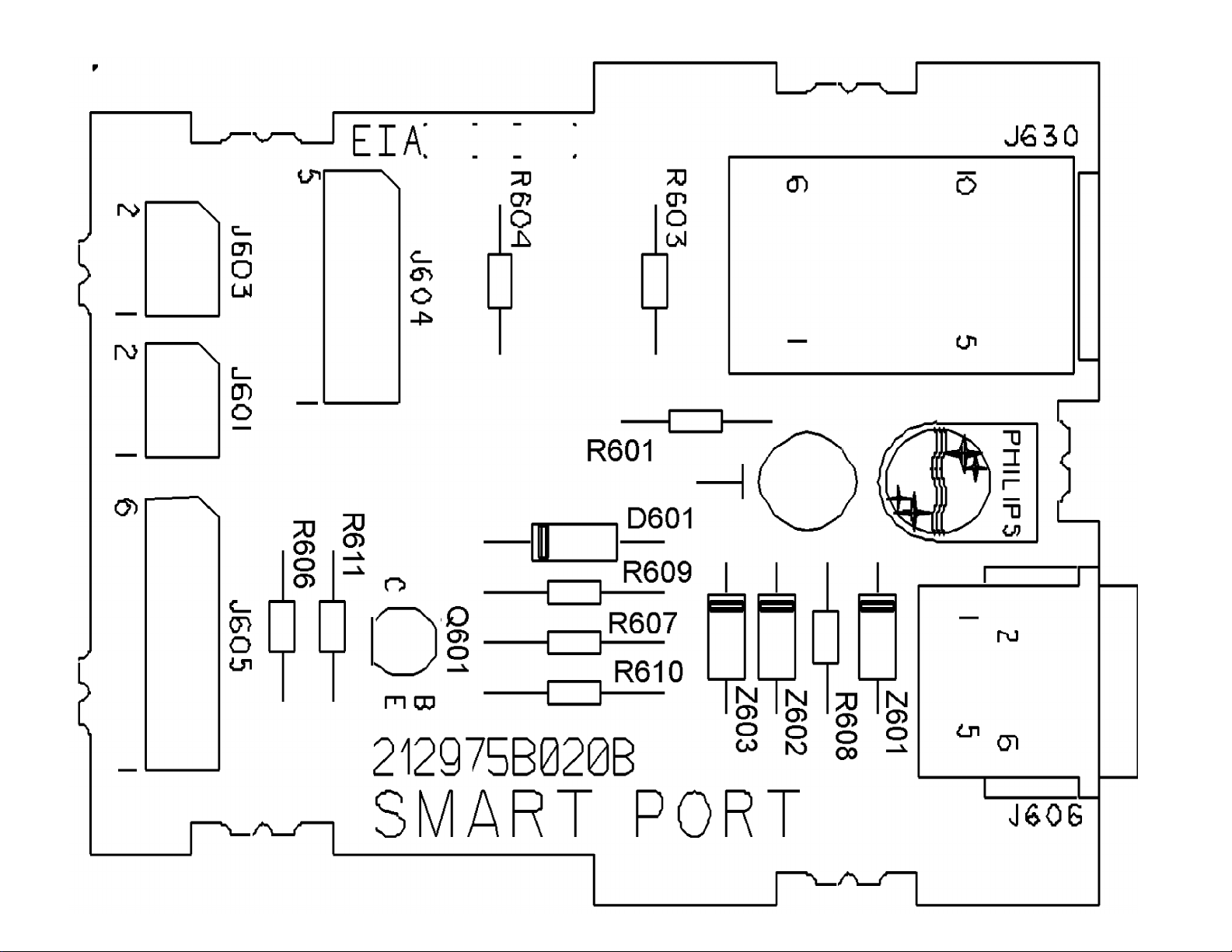
All Models (7562) - LODGING/SMART PORT PANEL PCB

Adjustment and Test Point Layout
Service Adjustment Notes:
Caution: The B8 Chassis incorporates a "Hot" ground system. Always use a
separate isolation transformer when applying power to the exposed chassis.
Unless Otherwise Specified:
1. All service adjustments are "Hot" voltagewise. For maximum safety, ensure the use
of properly insulated tools.
2. Many of the following adjustments are made through software intervention. The
remote transmitter supplied with the set may be used in order to modify register
values stored within the EEPROM IC on the Main Chassis Board Assembly. The
G96SVC Service Remote is an ideal tool for this purpose. Order 4835 219 17656.
Refer to the SERVICE MODE covered later.
3. Refer to the Component Location Diagram (Figure 1) for a quick location of test
points or service adjustable controls.
4. Grid locations (Ex.: D-2) next to control reference numbers refer to the Main Chassis
Printed Circuit Board Illustrations.

Focus
1. Tune to a local station and adjust the Focus Control (located on the Flyback
Transformer) for best picture details at high light conditions.
Screen Control (G2) Setup (13", 19", & 20")
1. Apply an NTSC Color Bar test pattern, with the color "off", to the antenna input of
the TV Receiver.
2. Select the active channel.
3. Set all the customer picture controls to mid-range.
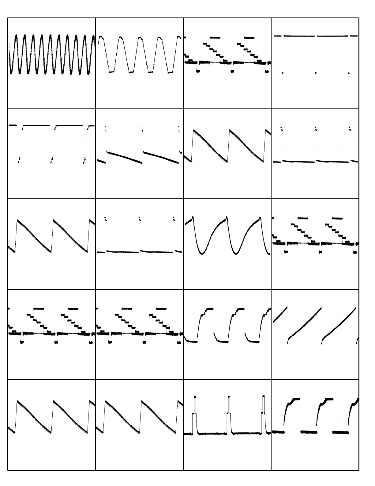
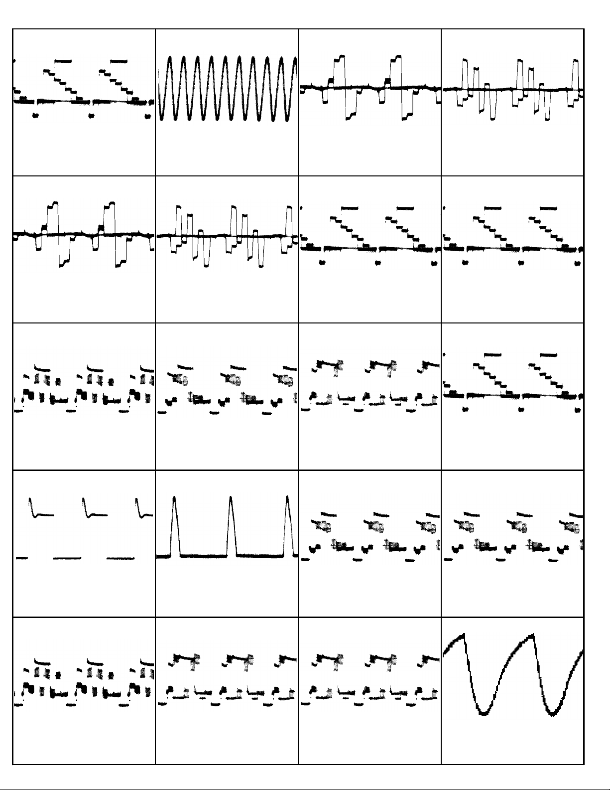
4. Using an oscilloscope measure and note the peak to peak voltage of the CRT
Cathodes. Use the legs of R11, R12, and R13 which tie to the CRT socket.
5. Using the cathode with the highest peak to peak voltage, noted in step 4, adjust the
Screen Voltage (G2) control (located on the Flyback Transformer) to obtain 120Vp-p.
Screen Control (G2) Setup (25" & 27")
1. Apply an NTSC Color Bar test pattern, with the color "off", to the antenna input of
the TV Receiver.
2. Select the active channel.
3. Set all the customer picture controls to mid-range.
4. Using an oscilloscope measure and note the peak to peak voltage of the CRT
Cathodes. Use the legs of R60, R61, and R62 which tie to the CRT socket.
5. Using the cathode with the highest peak to peak voltage, noted in step 4, adjust the
Screen Voltage (G2) control (located on the Flyback Transformer) to obtain 120Vp-p.
Adjusting The Picture
Note: The Color Purity and Convergence Adjustments described below should be performed
only after installation of a new CRT or Deflection Yoke Assembly otherwise, it will not
be necessary to remove the rubber wedges. Minor corrections for purity and convergence

can be accomplished through the use of the Purity and Convergence Assembly located on
the neck of the CRT.
Degaussing the Receiver
1. Position the TV receiver so that the screen faces the same direction (North, South,
East, or West) that it will be facing while in use.
2. Before the set is turned on, thoroughly Degauss the entire receiver.
a) Move a Degaussing Coil in a circular motion slowly around the sides and the front
face plate of the receiver.
b) Withdraw the Degaussing Coil from the receiver at least six feet before disconnecting
it from its power source.
Pre-Convergence Adjustments
(Perform Degauss Procedure first)
1. Place the multi-pole Purity and Convergence Assembly with the 2-Y pole Purity
Rings directly in the gap between the G2 and G3 (Focus Grids). (As shown in Figure
2)
2. Connect a Center Cross or Crosshatch pattern to the Antenna terminals.
3. Enter Service Page "G" (White Balance). Set the Green control to minimum.
4. Loosen the Yoke Clamp screws, pull the Yoke back and remove the three Yoke
wedges.
5. Slide the yoke all the way forward so that it rests against the bell of the CRT.
6. Tighten the Yoke Clamp screw so that the Yoke does not drop away from the bell of
the CRT.
7. Slowly spread and, if necessary, rotate the 2-Y pole purity rings so that the red and
blue lines are at least parallel and preferably coincide at the 6:00 and 12:00 position.
8. Do not exit Service Page "G".

Color Purity Adjustment
1. Connect a White Screen signal to the Antenna terminals.
2. Use Service Page G to set the Green control to maximum. Set the Blue control to
minimum.
3. Enter Service Page A.
4. Note that the set is in bank ("00").
5. Press the Channel Up (Cursor Up) button on the Remote transmitter to change the
Register to 68.
6. Note the Value stored in Register 68 Value .......
7. Press the Volume down button on the Remote Transmitter to set the value to its
minimum (00).
8. Slowly spread the 2-X Pole Purity Rings to center the Green portion of the screen
leaving the same amount of Red on the right side as there is Blue on the left.
9. Loosen the Yoke Clamp screws and slide the Yoke back to the point of best Green
Purity.
10. Tighten the Yoke Clamp screw slightly so that the Yoke can still be moved with some
friction.
11. Proceed to Static Center Convergence.
12. Re-enter Service Page A, Bank 00 and Register 68.
13. Reset this register to the value noted in step 6.
14. Re-enter Service Page G and reset the Green and Blue Registers to their mid-range
positions.

Static Center Convergence
Review Pre-Convergence Information
1. Connect a Center Cross pattern or a Crosshatch pattern to the Antenna input to ensure
that the yoke is not tilted. Rotate the yoke, if necessary, to obtain a level raster.
2. Use Service Page G to set the Green control to minimum.
3. Set the Blue control to its mid-range position.
4. Slowly spread and, if necessary, rotate the 4-Pole Magnetic Rings to converge Red
and Blue lines at the center of the screen.
5. Reset the Green Control to mid-range.
6. Slowly spread and, if necessary, rotate the 6-Pole Magnetic Rings to converge
Red/Blue on Green lines at the center of the screen.
7. Repeat the procedure for optimum performance.
Dynamic Edge Convergence
Review Pre-Convergence Information
Note: Three rubber wedges are used to secure the correct position of the Deflection Yoke They
are to ultimately be placed as shown in figure C or F of this display.
1. Apply a crosshatch pattern signal to the antenna input.
2. Use Service Page "G" to set the green control to minimum.
3. Tilt the Yoke Up and Down to converge the Red and Blue vertical lines at the 6 and
12 o'clock positions and the Red and Blue Horizontal lines at the 3 and 9 o'clock
positions
4. When the correct position has been found, place a rubber wedge between the Yoke
and the CRT. If the yoke is tilted UP, place wedge 1 as shown in Figure A. If the
Yoke is tilted DOWN, place wedge 1 as shown in Figure D.
5. Tilt the Yoke to the left and right to find the point of best possible convergence of the
Red and Blue lines at the edges, top and bottom of the screen.

When the correct position is located, place wedges 2 and 3 as seen in Figure B or E of
the
6. Now remove wedge 1 and place it as shown in Figure C or F.
7. Set the green control back to its mid-range position.
8. Proceed to the White Balance procedure.
SERVICE MODE
Note: Many of the following adjustments are made through software intervention. A
Remote Transmitter is required in order to modify register values stored within the
EEPROM IC on the Main Chassis Board.
The G96SVC Service Remote is an ideal tool for this purpose. Order 4835 219 17656.
The service mode makes it possible to change the values of special memory registers in
the EEPROM IC (IC302). These registers affect the customer adjustments and other
functions. These registers also make many other service adjustments possible that
previously would have been handled by conventional controls mounted on the P.C.
Board.
Service Mode Entry and Exit:
Using the remote transmitter, enter the following seven-button sequence to activate the
Service Mode:
06-25-96-Menu
Note: This sequence must be entered consecutively without allowing the on screen
display to time out between entries.
Exit Service Mode
To exit the Service Test Mode procedure enter Service Page I and press the Volume Up
button on the remote transmitter.

To save the current modification of the register data, disconnect the set from its AC
source.
When the receiver is operating in the Service Mode, all normal on-screen displays are
suppressed and replaced by a special display.
Service Mode Display
• The first letter on the top line is an S. This letter indicates that the set is in the Service
Mode.
• The second letter indicates which Service Page the set is currently in.
• The number showing at the top right corner of the display is the currently tuned
channel.
• The number shown in the upper middle of the display (31350100661) is the current
level of software in use.

Spare Parts List
MAIN CHASSIS
CAPACITORS
C208 22uF., 50V, 20%, Electrolytic. . . . . 4835 124 47503
C222 4700pF., 10%, 50V, Carbon (All 19", 25"
, & 27" Models w/DBX, LCS, & Mono) . . 4835 122 87415
C222 47pF., 5%, 50V, Carbon (All 25" & 27" M
odels w/DBM Stereo). . . . . . . . . . 4835 122 87017
C222 100pF., 5%, 50V, Carbon (All 25" & 27"
Models w/LC Stereo). . . . . . . . . . 4835 122 87012
C223 330pF., 5%, 50V, Carbon (Certain Models
only). . . . . . . . . . . . . . . . . 4835 122 87287
C224 1.0uF., 20%, 50V, Electrolytic (Certain
Models only) . . . . . . . . . . . . . 4835 121 47406
C225 0.470uF.,100V, Polyester . . . . . . . 4835 121 47222
C226 0.1uF., 100V, Polyester. . . . . . . . 4822 121 41608
C228 1uF, 50V, 20%, Electrolytic. . . . . . 4835 121 47406
C229 0.1uF., 63V, Polyester . . . . . . . . 4835 121 47602
C230 3300pF, 50V, 10%, Ceramic. . . . . . . 4835 122 87294
C231 4700pF, 50V, 10%, Ceramic. . . . . . . 4835 122 87415
C232 1uF, 50V, 20%, Electrolytic. . . . . . 4835 121 47406
C233 2200pF 50V, 10%, Ceramic . . . . . . . 4835 122 87544
C236 2200pF 50V, 10%, Ceramic . . . . . . . 4835 122 87538
C237 2200pF 50V, 10%, Ceramic . . . . . . . 4835 122 87538
C238 100pF, 50V, 5%, Ceramic. . . . . . . . 4835 122 87012
C239 100pF, 50V, 5%, Ceramic. . . . . . . . 4835 122 87012
C244 100pF, 50V, 10%, Ceramic . . . . . . . 4835 122 87061
C245 2.2uF.,50V, 20%, Electrolytic. . . . . 4835 124 47502
C246 2200pF 50V, 10%, Ceramic . . . . . . . 4835 122 87538
C247 100pF., 10%, 50V, Ceramic (Certain Mode
ls only) . . . . . . . . . . . . . . . 4835 122 47004
C248 0.1uF., 63V, Polyester (Certain Models
only). . . . . . . . . . . . . . . . . 4835 121 47602
C249 0.1uF., 63V, Electrolytic. . . . . . . 4835 121 47602
C250 2200pF 50V, 10%, Ceramic . . . . . . . 4835 122 87538
C251 2200pF 50V, 10%, Ceramic . . . . . . . 4835 122 87538
C252 2200pF 50V, 10%, Ceramic . . . . . . . 4835 122 87538
C253 22uF., 50V, 20%, Electrolytic. . . . . 4835 124 47503
C254 100pF., 50V, 10%, Ceramic. . . . . . . 4835 122 87023
C255 10uF., 50V, 20%, Electrolytic. . . . . 4835 124 47499
C256 27pF., 50V, 5%, Ceramic. . . . . . . . 4835 122 47607
C257 27pF., 50V, 5%, Ceramic. . . . . . . . 4835 122 47607
C258 27pF., 50V, 5%, Ceramic. . . . . . . . 4835 122 47607
C260 100uF., 10V, Electrolytic. . . . . . . 4835 124 47704
C261 2200pF 50V, 10%, Ceramic . . . . . . . 4835 122 87538
C262 1000pF 50V, 10%, Ceramic . . . . . . . 4835 122 87024
C264 15pF., 50V, 5%, Ceramic. . . . . . . . 4835 122 87592
C266 2200pF., 50V, 10%, Ceramic . . . . . . 4835 122 87538
C267 470uF., 16V, Electrolytic. . . . . . . 4835 121 47387
C268 0.1uF., 50V, 10%, Ceramic. . . . . . . 4835 122 87061
C274 82pF., 50V, 5%, Ceramic. . . . . . . . 4835 122 47612
C275 0.1uF., 63V, Polyester (Certain Models
only). . . . . . . . . . . . . . . . . 4835 121 47602
C280 4700pF., 50V, 10%, Ceramic . . . . . . 4835 122 87503
C291 220uF., 50V, Electrolytic. . . . . . . 4835 124 47703
C293 1uF., 50V, 20%, Electrolytic . . . . . 4835 121 47406
C294 100uF., 10V, Electrolytic. . . . . . . 4835 124 47704
C307 4700pF., 50V, 10%, Ceramic . . . . . . 4835 122 87503
C310 33pF., 50V, 5%, Ceramic. . . . . . . . 4835 122 87414
C311 33pF., 50V, 5%, Ceramic. . . . . . . . 4835 122 87414
C314 1uF., 50V, 20%, Electrolytic . . . . . 4835 121 47406
C315 0.022uF.,50V, 10%, Ceramic . . . . . . 4835 122 87538
C316 22uF., 25V, 20%, Electrolytic. . . . . 4835 124 47707
C317 1000pF., 50V, 10%, Ceramic . . . . . . 4835 122 87023
C318 1000pF., 50V, 10%, Ceramic . . . . . . 4835 122 87023
C320 15pF., 5%, 50V, Carbon (Certain Models
only). . . . . . . . . . . . . . . . . 4835 122 87592
C321 0.01pF., 50V, 10%, Ceramic . . . . . . 4835 122 87024
C322 15pF., 5%, 50V, Carbon (Certain Models
only). . . . . . . . . . . . . . . . . 4835 122 87592
C323 100pF., 50V, 5%, Ceramic . . . . . . . 4835 122 87012
C325 0.01pF., 50V, 10%, Ceramic . . . . . . 4835 122 87024
C337 1.0uF., 20%, 50V, Electrolytic (Certain
Models only) . . . . . . . . . . . . . 4835 121 47406
C338 0.01pF., 50V, +80%, -20%, Ceramic. . . 4835 122 47616
C339 100pF., 50V, 5%, Ceramic . . . . . . . 4835 122 87012
C340 33pF., 50V, 5%, Ceramic. . . . . . . . 4835 122 87414
C341 33pF., 50V, 5%, Ceramic. . . . . . . . 4835 122 87414
C342 33pF., 50V, 5%, Ceramic. . . . . . . . 4835 122 87414
C343 33pF., 50V, 5%, Ceramic. . . . . . . . 4835 122 87414
C344 4.7uF., 20%, 50V, Electrolytic (Certain
Models only) . . . . . . . . . . . . . 4835 124 47506
C350 47uF., 16V, 20%, Electrolytic. . . . . 4835 124 47567
C351 1.0uF., 20%, 50V, Electrolytic (Certain
Models only) . . . . . . . . . . . . . 4835 121 47406
C357 39pF., 5%, 50V, Carbon (Used in Commerc
ial Models). . . . . . . . . . . . . . 4835 122 87016
C358 33pF., 50V, 5%, Ceramic (Used in Commer
cial Models) . . . . . . . . . . . . . 4835 122 87414
C375 2.2uF, 50V, 20%, Electrolytic. . . . . 4835 124 47502
C376 1000pF., 10%, 50V, Carbon (Used in Comm
ercial Models) . . . . . . . . . . . . 4835 122 87023
C377 0.033uF., 10%, 50V, Carbon (Used in Non
-Commercial Models). . . . . . . . . . 4835 122 87452
S = Safety Part Be sure to use exact replacement part.
C381 0.01pF., 50V, 10%, Ceramic . . . . . . 4835 122 87024
C383 1uF., 50V, 20%, Electrolytic . . . . . 4835 121 47406
C384 470pF., 50V, 10%, Ceramic. . . . . . . 4835 122 47614
C390 100pF., 5%, 50V, Carbon (Certain Models
only). . . . . . . . . . . . . . . . . 4835 122 87012
C391 100pF., 5%, 50V, Carbon (Certain Models
only). . . . . . . . . . . . . . . . . 4835 122 87012
C392 100pF., 5%, 50V, Carbon (Certain Models
only). . . . . . . . . . . . . . . . . 4835 122 87012
S C400 0.220uF., 250V, Mylar. . . . . . . . . 4835 121 47597
C401 2200pF., 250VAC, Ceramic (All 19" w/SVH
S & 20", 25", & 27" Latam Models w/AMV) 4835 122 47619
C401 4700pF., 250VAC, Ceramic (All 19", 20",
25", & 27" & All Latam Models w/out AM 4835 122 97023
C405 470uF., 400V, Electrolytic (All 19" w/S
VHS & 20", 25", & 27" Latam Models w/AM 4835 124 47717
C405 680uF., 200V, Electrolytic (All 25", &
27" Commercial/Latam Models w/out AMV) 4835 124 47674
C405 680uF., 200V, Electrolytic (All 19" & 2
0" Latam Models w/out AMV) . . . . . . 4835 124 47064
C407 0.015uF., 400V, Polyester. . . . . . . 4835 121 47203
C408 0.120uF., 63V, Polyester . . . . . . . 4835 121 47001
C409 0.015uF., 400V, Polyester. . . . . . . 4835 121 47203
C410 47uF., 25V, 20%, Electrolytic. . . . . 4835 124 47708
C411 2200pF., 50V, 10%, Ceramic . . . . . . 4835 122 87544
C412 10uF., 50V, 20%, Electrolytic. . . . . 4835 124 47499
C413 2200pF., 50V, 10%, Ceramic . . . . . . 4835 122 87544
C414 470pF., 50V, 10%, Ceramic. . . . . . . 4835 122 47614
C415 1000pF., 1KV, 10%, Ceramic . . . . . . 4835 122 47373
C416 0.1uF, 50V, Ceramic. . . . . . . . . . 4835 122 87375
C418 1000pF, 500V, 10%, Ceramic . . . . . . 4835 122 47384
C419 1000uF., 16V, Electrolytic . . . . . . 4835 124 47699
C423 1000uF., 1KV, 10%, Ceramic . . . . . . 4835 122 47373
C426 4700pF., 20%, 125V, Ceramic (Certain Mo
dels only) . . . . . . . . . . . . . . 4835 122 47618
C427 1000uF., 500V 10%, Ceramic . . . . . . 4835 122 47384
C430 680pF., 1KV, 10%, Ceramic. . . . . . . 4835 122 47633
C431 100uF., 200V, Electrolytic . . . . . . 4835 124 47038
C433 1000pF., 1KV, 10%, Ceramic . . . . . . 4835 122 47373
C435 470pF., 1KV, 10%, Ceramic. . . . . . . 4835 122 47459
C437 470pF., 1KV, 10%, Ceramic. . . . . . . 4835 122 47459
C441 0.010uF , 50V, 10%, Ceramic. . . . . . 4835 122 87024
C442 3900pF., 500V, 10%, Ceramic. . . . . . 4835 122 47623
C443 1000uF., 25V, Electrolytic . . . . . . 4835 124 47583
C445 1000uF., 500V 10%, Ceramic . . . . . . 4835 122 47384
C447 1000uF., 16V, Electrolytic . . . . . . 4835 124 47699
C448 3900pF., 500V, 10%, Ceramic. . . . . . 4835 122 47623
C450 2200uF., 25V, Electrolytic . . . . . . 4835 124 47593
C451 1uF., 50V, 20%, Electrolytic . . . . . 4835 121 47406
C453 0.120uF., 63V, Polyester . . . . . . . 4835 121 47001
C457 1uF., 50V, 20%, Electrolytic . . . . . 4835 121 47406
C460 1000uF., 500V, 10%, Ceramic. . . . . . 4835 122 47384
C461 1uF., 250V, Electrolytic . . . . . . . 4835 124 47536
C462 1uF., 50V, 20%, Electrolytic . . . . . 4835 121 47406
C463 0.100uF., 250V, Electrolytic . . . . . 4835 121 47278
S C498 4700pF., 250V, Ceramic . . . . . . . . 4835 122 97023
C501 0.010uF., 50V, +80%, -20%, Ceramic . . 4835 122 47616
C502 470pF., 500V, 10%, Ceramic . . . . . . 4835 122 47211
C503 1000pF., 500V, 10%, Ceramic. . . . . . 4835 122 47384
C504 0.100uF., 250V, Electrolytic . . . . . 4835 121 47278
S C505 0.010uF.,1.6kV, Polypropylene (All 25"
& 27" Models). . . . . . . . . . . . . 4835 121 47611
S C505 4700pF., 1.6kV, Polypropylene (19", 20"
, 25", 27" Commercial Models w/ Smart P 4835 121 47613
S C505 3900pF., 5%, 2kV, Polypropylene (19" Co
mmercial & LATAM w/ Toshiba CRT) . . . 4835 121 47619
S C506 470pF., 10%, 2kV, Ceramic (19" Commerci
al & LATAM w/ Toshiba CRT) . . . . . . 4835 122 47638
S C506 270pF., 10%, 2kV, Ceramic (19" Commerci
al w/ Toshiba CRT) . . . . . . . . . . 4835 122 47075
S C506 330pF., 10%, 2kV, Ceramic (20" Commerci
al w/ Toshiba CRT) . . . . . . . . . . 4835 122 47637
S C506 680pF., 10%, 2kV, Ceramic (All 20" Lata
m & all 25" Models). . . . . . . . . . 4835 122 47584
S C506 820pF., 10%, 2kV, Ceramic (All 27" Mode
ls). . . . . . . . . . . . . . . . . . 4835 122 47639
C507 0.270uF., 250V, Polypropylene (All 20"
Latam Models). . . . . . . . . . . . . 4835 121 47618
C507 0.360uF., 250V,.Polypropylene (All 20"
Commercial models w/out Channel 1) . . 4835 121 47606
C507 0.430uF., 250V, Polypropylene (All 27"
Models & 20" Latam Models) . . . . . . 4835 121 47607
C507 0.470uF., 250V, Polypropylene (All 25"
Models w/out Smart Port) . . . . . . . 4835 121 47608
C508 1500pF., 10%, 500V, Ceramic (All 20", 2
5", & 27" Models). . . . . . . . . . . 4835 122 47409
C511 100pF., 2KV, 10%, Ceramic. . . . . . . 4835 122 47631
C512 15uF., 50V, 20%, Electrolytic. . . . . 4835 124 47606
C513 15uF., 50V, 20%, Electrolytic. . . . . 4835 124 47606
C514 15uF., 50V, 20%, Electrolytic. . . . . 4835 124 47606
C520 1uF., 50V, 20%, Electrolytic . . . . . 4835 121 47406
C521 100pF., 50V, 5%, Ceramic . . . . . . . 4835 122 87012

Spare Parts List (continued)
C530 10uF., 50V, 20%, Electrolytic. . . . . 4835 124 47499
C550 0.100uF., 63V, Electrolytic. . . . . . 4835 121 47602
C551 0.220uF., 63V, Electrolytic. . . . . . 4835 121 47603
C552 220pF., 50V, 5%, Ceramic . . . . . . . 4835 122 87376
C553 470pF., 500V, 10%, Ceramic . . . . . . 4835 122 47211
C554 470pF., 500V, 10%, Ceramic . . . . . . 4835 122 47211
C556 0.100uF., 63V, Polyester . . . . . . . 4835 121 47602
C557 100uF., 50V, Electrolytic. . . . . . . 4835 124 47563
C559 1000pF., 50V, 10%, Ceramic . . . . . . 4835 122 87023
C560 1000pF., 50V, 10%, Ceramic . . . . . . 4835 122 87023
C568 47uF., 250V, Electrolytic. . . . . . . 4835 124 47137
C571 10uF., 50V, 20%, Electrolytic. . . . . 4835 124 47499
C573 047uF., 250V, Polyester. . . . . . . . 4835 121 47601
C700 100uF., 25V, Electrolytic (Certain Mode
ls only) . . . . . . . . . . . . . . . 4835 124 47501
C701 4700pF., 10%, 50V, Carbon (Certain Mode
ls only) . . . . . . . . . . . . . . . 4835 122 87415
C702 0.22uF., 63V, Polyester (Certain Models
only). . . . . . . . . . . . . . . . . 4835 121 47603
C703 1.0uF., 20%, 50V, Electrolytic (Certain
Models only) . . . . . . . . . . . . . 4835 121 47406
C704 47uF., 20%, 25V, Electrolytic (Certain
Models only) . . . . . . . . . . . . . 4835 124 47708
C705 10uF., 20%, 50V, Electrolytic (Certain
Models only) . . . . . . . . . . . . . 4835 124 47499
C706 0.022uF., 10%, 50V, Carbon (Certain Mod
els only). . . . . . . . . . . . . . . 4835 122 87538
C707 1.0uF., 20%, 50V, Electrolytic (Certain
Models only) . . . . . . . . . . . . . 4835 121 47406
C708 0.1uF., 63V, Polyester (Certain Models
only). . . . . . . . . . . . . . . . . 4835 121 47602
C709 1.0uF., 20%, 50V, Electrolytic (Certain
Models only) . . . . . . . . . . . . . 4835 121 47406
C710 1000pF., 10%, 50V, Carbon (Certain Mode
ls only) . . . . . . . . . . . . . . . 4835 122 87023
C711 2700pF., 10%, 50V, Carbon (Certain Mode
ls only) . . . . . . . . . . . . . . . 4835 122 87502
C712 0.1uF., 63V, Polyester (Certain Models
only). . . . . . . . . . . . . . . . . 4835 121 47602
C713 10uF., 20%, 50V, Electrolytic (Certain
Models only) . . . . . . . . . . . . . 4835 124 47499
C714 2.2uF., 20%, 50V, Electrolytic (Certain
Models only) . . . . . . . . . . . . . 4835 124 47502
C715 10uF., 20%, 50V, Electrolytic (Certain
Models only) . . . . . . . . . . . . . 4835 124 47499
C716 10uF., 20%, 50V, Electrolytic (Certain
Models only) . . . . . . . . . . . . . 4835 124 47499
C718 100pF., 5%, 50V, Carbon (Certain Models
only). . . . . . . . . . . . . . . . . 4835 122 87012
C719 100pF., 5%, 50V, Carbon (Certain Models
only). . . . . . . . . . . . . . . . . 4835 122 87012
C720 100pF., 10%, 50V, Carbon (Certain Model
s only). . . . . . . . . . . . . . . . 4835 122 87023
C721 1000pF., 10%, 50V, Carbon (Certain Mode
ls only) . . . . . . . . . . . . . . . 4835 122 87023
C722 10uF., 20%, 50V, Electrolytic (Certain
Models only) . . . . . . . . . . . . . 4835 124 47499
C723 10uF., 20%, 50V, Electrolytic (Certain
Models only) . . . . . . . . . . . . . 4835 124 47499
C724 10uF., 20%, 50V, Electrolytic (Certain
Models only) . . . . . . . . . . . . . 4835 124 47499
C725 10uF., 20%, 50V, Electrolytic (Certain
Models only) . . . . . . . . . . . . . 4835 124 47499
C726 10pF., 0.5%, 50V, Carbon (Certain Model
s only). . . . . . . . . . . . . . . . 4835 122 87412
C727 10pF., 0.5%, 50V, Carbon (Certain Model
s only). . . . . . . . . . . . . . . . 4835 122 87412
C728 1000pF., 10%, 50V, Carbon (Certain Mode
ls only) . . . . . . . . . . . . . . . 4835 122 87023
C729 1000pF., 10%, 50V, Carbon (Certain Mode
ls only) . . . . . . . . . . . . . . . 4835 122 87023
C730 47uF., 20%, 25V, Electrolytic (Certain
Models only) . . . . . . . . . . . . . 4835 124 47708
C731 1000pF., 10%, 50V, Carbon (Certain Mode
ls only) . . . . . . . . . . . . . . . 4835 122 87023
C732 47uF., 20%, 25V, Electrolytic (Certain
Models only) . . . . . . . . . . . . . 4835 124 47708
C733 47uF., 20%, 25V, Electrolytic (Certain
Models only) . . . . . . . . . . . . . 4835 124 47708
C734 100uF., 25V. Electrolytic (Certain Mode
ls only) . . . . . . . . . . . . . . . 4835 124 47501
C735 47uF., 20%, 25V, Electrolytic (Certain
Models only) . . . . . . . . . . . . . 4835 124 47708
C736 0.22uF., 50V, Carbon (Certain Models on
ly). . . . . . . . . . . . . . . . . . 0483 512 28708
C737 0.22uF., 50V, Carbon (Certain Models on
ly). . . . . . . . . . . . . . . . . . 0483 512 28708
C738 10uF., 20%, 50V, Electrolytic (Certain
Models only) . . . . . . . . . . . . . 4835 124 47499
C739 10uF., 20%, 50V, Electrolytic (Certain
Models only) . . . . . . . . . . . . . 4835 124 47499
C740 47uF., 20%, 25V, Electrolytic (Certain
Models only) . . . . . . . . . . . . . 4835 124 47708
S = Safety Part Be sure to use exact replacement part .
C741 1000pF., 10%, 50V, Carbon (Certain Mode
ls only) . . . . . . . . . . . . . . . 4835 122 87023
C743 0.027uF., 10%, 50V, Electrolytic (Certa
in Models only). . . . . . . . . . . . 4835 121 47586
C744 2200pF., 50V, 10%, Ceramic (Certain Mod
els only). . . . . . . . . . . . . . . 4835 122 87544
C745 0.47uF., 100V, Polyester (Certain Model
s only). . . . . . . . . . . . . . . . 4835 121 47222
C746 2200pF., 50V, 10%, Ceramic (Certain Mod
els only). . . . . . . . . . . . . . . 4835 122 87544
C747 0.033uF., 10%, 50V, Electrolytic (Certa
in Models only). . . . . . . . . . . . 4835 121 47587
C748 2200pF., 50V, 10%, Ceramic (Certain Mod
els only). . . . . . . . . . . . . . . 4835 122 87544
C770 1000uF., 25V, Electrolytic . . . . . . 4835 124 47583
C772 10uF., 50V, 20%, Electrolytic. . . . . 4835 124 47499
C773 22uF., 20%, 50V, Electrolytic (Certain
Models only) . . . . . . . . . . . . . 4835 124 47503
C780 0.22uF., 63V, Polyester (Certain Models
only). . . . . . . . . . . . . . . . . 4835 121 47603
C781 0.22pF., 63V, Polyester (Certain Models
only). . . . . . . . . . . . . . . . . 4835 121 47603
C784 0.12uF., 63V, Polyester (Certain Models
only). . . . . . . . . . . . . . . . . 4835 121 47001
C785 0.12uF., 63V, Polyester (Certain Models
only). . . . . . . . . . . . . . . . . 4835 121 47001
C790 330pF., 5%, 50V, Carbon (Certain Models
only). . . . . . . . . . . . . . . . . 4835 122 87287
C791 10uF., 20%, 50V, Electrolytic (Certain
Models only) . . . . . . . . . . . . . 4835 124 47499
C792 330pF., 5%, 50V, Carbon (Certain Models
only). . . . . . . . . . . . . . . . . 4835 122 87287
C793 10uF., 20%, 50V, Electrolytic (Certain
Models only) . . . . . . . . . . . . . 4835 124 47499
C794 3300pF., 10%, 50v, Carbon (Certain Mode
ls only) . . . . . . . . . . . . . . . 4835 122 87294
C796 3300pF., 10%, 50V, Carbon (Certain Mode
ls only) . . . . . . . . . . . . . . . 4835 122 87294
RESISTORS
R218 220 ohm, 5%, 1/10W, Metal Film . . . . 4835 111 37371
R219 15k, 5%, 1/10W, Metal Film . . . . . . 4835 111 37458
R222 15k, 5%, 1/2W, Metal Film. . . . . . . 4835 116 57698
R224 620k, 5%, 1/2W, Metal Film (Certain Mod
els only). . . . . . . . . . . . . . . 4835 116 57734
R225 39.0k, 1%, 1/10W, Metal Film . . . . . 4835 111 27041
R226 2.2 ohm, 5%, 1/3W, Metal Film. . . . . 4822 052 10228
R229 82k, 5%, 1/10W, Metal Film . . . . . . 4835 111 37277
R230 1.0k, 5%, 1/2W, Metal Film . . . . . . 4835 116 57685
R231 1.0k, 5%, 1/8W, Metal Film . . . . . . 4835 111 37022
R232 15k, 5%, 1/10W, Metal Film . . . . . . 4835 111 37458
R233 100 ohm, 5%, 1/2W, Metal Film. . . . . 4835 116 57684
R234 100 ohm, 5%, 1/2W, Metal Film. . . . . 4835 116 57684
R235 1.0k, 5%, 1/10W, Metal Film. . . . . . 4822 051 10102
R236 1.0k, 5%, 1/10W, Metal Film. . . . . . 4822 051 10102
R240 2.2 ohm, 5%, 1/2W, Metal Film. . . . . 4835 116 57653
R243 75 ohm, 5%, 1/10W, Metal Film (Certain
Models only) . . . . . . . . . . . . . 4835 111 37276
R244 620 ohm, 5%, 1/2W, Metal Film. . . . . 4835 116 57733
R245 1.0k, 5%, 1/2W, Metal Film . . . . . . 4835 116 57685
R246 100 ohm, 5%, 1/2W, Metal Film. . . . . 4835 116 57684
R247 100 ohm, 5%, 1/2W, Metal Film. . . . . 4835 116 57684
R248 100 ohm, 5%, 1/2W, Metal Film. . . . . 4835 116 57684
R249 1.0k, 5%, 1/2W, Metal Film . . . . . . 4835 116 57685
R250 1.0k, 5%, 1/8W, Metal Film . . . . . . 4835 111 37022
R251 150 ohm, 5%, 1/4W, Metal Film. . . . . 4835 111 37058
R252 2.2k, 5%, 1/10W, Metal Film. . . . . . 4835 111 37234
R253 22 ohm, 5%, 1/2W, Metal Film . . . . . 4835 116 57708
R255 220 ohm, 5%, 1/10W, Metal Film . . . . 4835 111 37371
R256 1.0k, 5%, 1/10W, Metal Film. . . . . . 4822 051 10102
R266 10 ohm, 5%, 1/3W, Metal Film . . . . . 4822 111 30508
R273 100 ohm, 5%, 1/2W, Metal Film. . . . . 4835 116 57684
R275 10 ohm, 5%, 1/3W, Metal Film (Certain M
odels only). . . . . . . . . . . . . . 4822 111 30508
R276 1.0k, 5%, 1/2W, Metal Film (Certain Mod
els only). . . . . . . . . . . . . . . 4835 116 57685
R277 75 ohm, 5%, 1/2W, Metal Film (Certain M
odels only). . . . . . . . . . . . . . 4835 116 57739
R280 180 ohm, 5%, 1/10W, Metal Film . . . . 4835 111 37229
R281 180 ohm, 5%, 1/10W, Metal Film . . . . 4835 111 37229
R291 15k, 5%, 1/2W, Metal Film. . . . . . . 4835 116 57698
R292 15k, 5%, 1/2W, Metal Film. . . . . . . 4835 116 57698
R293 10 ohm, 5%, 1/2W, Metal Film . . . . . 4835 116 57097
S R294 39 ohm, 5%, 1W, Metal Oxide. . . . . . 4835 116 67259
R296 1.0k, 5%, 1/2W, Metal Film . . . . . . 4835 116 57685
R298 68 ohm, 5%, 1/10W, Metal Film. . . . . 4835 111 37408
R301 15k, 5%, 1/10W, Metal Film . . . . . . 4835 111 37458
R302 75k, 5%, 1/10W, Metal Film . . . . . . 4835 111 27055
R303 10k, 5%, 1/10W, Metal Film . . . . . . 4835 111 37216
R304 6.2k, 5%, 1/10W, Metal Film (All Non-Co
mmercial Models) . . . . . . . . . . . 4835 111 37269
R304 5.6k, 5%, 1/10W, Metal Film (All Commer
cial Models) . . . . . . . . . . . . . 4835 111 37376

Spare Parts List (continued)
R305 10.0 ohm, 5%, 1/8W, Metal Film . . . . 4835 111 37132
R306 43k, 5%, 1/10W, Metal Film . . . . . . 4835 111 37374
R307 2.2k, 5%, 1/10W, Metal Film (All Non-Co
mmercial Models) . . . . . . . . . . . 4835 111 37234
R307 3.3k, 5%, 1/10W, Metal Film (All Commer
cial Models) . . . . . . . . . . . . . 4835 111 37247
R308 4.7k, 5%, 1/10W, Metal Film. . . . . . 4835 111 27052
R309 10.0k, 1%, 1/6W, Metal Film. . . . . . 4822 116 53022
R310 3.3k, 5%, 1/10W, Metal Film (All Non-Co
mmercial Models) . . . . . . . . . . . 4835 111 37247
R310 2.2k, 5%, 1/10W, Metal Film (All Commer
cial Models) . . . . . . . . . . . . . 4835 111 37234
R311 330 ohm, 5%, 1/10W, Metal Film . . . . 4835 111 37443
R312 330 ohm, 5%, 1/10W, Metal Film . . . . 4835 111 37443
R313 4.7k, 5%, 1/10W, Metal Film. . . . . . 4835 111 27052
R316 56k, 5%, 1/10W, Metal Film . . . . . . 4835 111 37477
R318 330 ohm, 5%, 1/2W, Metal Film. . . . . 4835 116 57713
R319 4.7k, 5%, 1/2W, Metal Film . . . . . . 4835 116 57724
R320 330 ohm, 5%, 1/2W, Metal Film. . . . . 4835 116 57713
R321 510k, 5%, 1/10W, Metal Film (All Non-Co
mmercial Models ). . . . . . . . . . . 4835 111 27053
R321 0 Ohm, Metal Film (All Commercial Model
s ). . . . . . . . . . . . . . . . . . 4835 111 27056
R325 100 ohm, 5%, 1/10W, Metal Film . . . . 4835 111 37432
R326 1.0k, 5%, 1/2W, Metal Film . . . . . . 4835 116 57685
R327 100 ohm, 5%, 1/10W, Metal Film . . . . 4835 111 37432
R328 1.0k, 5%, 1/2W, Metal Film . . . . . . 4835 116 57685
R330 4.7k, 5%, 1/2W, Metal Film . . . . . . 4835 116 57724
R331 5.6k, 5%, 1/10W, Metal Film. . . . . . 4835 111 37376
R332 5.6k, 5%, 1/10W, Metal Film. . . . . . 4835 111 37376
R333 5.6k, 5%, 1/10W, Metal Film. . . . . . 4835 111 37376
R334 1.0k, 5%, 1/2W, Metal Film (Certain Mod
els only). . . . . . . . . . . . . . . 4835 116 57685
R338 27k, 5%, 1/2W, Metal Film. . . . . . . 4835 116 57712
R340 10k, 5%, 1/2W, Metal Film (Certain Mode
ls only) . . . . . . . . . . . . . . . 4835 116 57686
R341 1.1k, 5%, 1/2W, Metal Film (Certain Mod
els only). . . . . . . . . . . . . . . 4835 116 57688
R342 1.0k, 5%, 1/2W, Metal Film (Certain Mod
els only). . . . . . . . . . . . . . . 4835 116 57685
R343 470 ohm, 5%, 1/2W, Metal Film (Certain
Models only) . . . . . . . . . . . . . 4835 116 57723
R344 1.0k, 5%, 1/2W, Metal Film (Certain Mod
els only). . . . . . . . . . . . . . . 4835 116 57685
R345 10k, 5%, 1/10W, Metal Film . . . . . . 4835 111 37216
R346 47k, 5%, 1/2W, Metal Film. . . . . . . 4835 116 57725
R347 10k, 5%, 1/2W, Metal Film. . . . . . . 4835 116 57686
R348 1.0k, 5%, 1/10W, Metal Film. . . . . . 4822 051 10102
R349 22k, 5%, 1/2W, Metal Film. . . . . . . 4835 116 57706
R350 47 ohm, 5%, 1/3W, Metal Film . . . . . 4835 116 57745
R351 1.0k, 5%, 1/2W, Metal Film (Certain Mod
els only). . . . . . . . . . . . . . . 4835 116 57685
R352 2.7k, 5%, 1/2W, Metal Film . . . . . . 4835 116 57711
R353 10k, 5%, 1/2W, Metal Film. . . . . . . 4835 116 57686
R354 10k, 5%, 1/2W, Metal Film. . . . . . . 4835 116 57686
R355 1.0k, 5%, 1/2W, Metal Film . . . . . . 4835 116 57685
R357 4.7k, 5%, 1/2W, Metal Film (Certain Mod
els only). . . . . . . . . . . . . . . 4835 116 57724
R358 10k, 5%, 1/2W, Metal Film (Certain Mode
ls only) . . . . . . . . . . . . . . . 4835 116 57686
R359 10k, 5%, 1/2W, Metal Film (Certain Mode
ls only) . . . . . . . . . . . . . . . 4835 116 57686
R360 1.0k, 5%, 1/2W, Metal Film (Certain Mod
els only). . . . . . . . . . . . . . . 4835 116 57685
R361 10k, 5%, 1/10W, Metal Film (Certain Mod
els only). . . . . . . . . . . . . . . 4835 111 37216
R362 10k, 5%, 1/10W, Metal Film . . . . . . 4835 111 37216
R363 10k, 5%, 1/10W, Metal Film . . . . . . 4835 111 37216
R364 100 ohm, 5%, 1/8W, Metal Film. . . . . 4835 111 37021
R365 4.7k, 5%, 1/10W, Metal Film. . . . . . 4835 111 27052
R367 1.5k, 5%, 1/10W, Metal Film. . . . . . 4835 111 37437
R368 820 ohm, 5%, 1/10W, Metal Film . . . . 4835 111 37466
R369 820 ohm, 5%, 1/10W, Metal Film . . . . 4835 111 37466
R370 820 ohm, 5%, 1/10W, Metal Film . . . . 4835 111 37466
R371 2.2k, 5%, 1/10W, Metal Film. . . . . . 4835 111 37234
R372 560 ohm, 5%, 1/10W, Metal Film . . . . 4835 111 27054
R373 560 ohm, 5%, 1/10W, Metal Film . . . . 4835 111 27054
R374 560 ohm, 5%, 1/10W, Metal Film . . . . 4835 111 27054
R375 1.5k, 5%, 1/10W, Metal Film (Certain Mo
dels only) . . . . . . . . . . . . . . 4835 111 37437
R377 10k, 5%, 1/10W, Metal Film . . . . . . 4835 111 37216
R378 820 ohm, 5%, 1/10W, Metal Film . . . . 4835 111 37466
R379 1.0k, 5%, 1/10W, Metal Film (Certain Mo
dels only) . . . . . . . . . . . . . . 4835 111 37217
R380 330 ohm, 5%, 1/10W, Metal Film (All Non
-Commercial Models). . . . . . . . . . 4835 111 37443
R380 22k, 5%, 1/10W, Metal Film (All Commerc
ial Models). . . . . . . . . . . . . . 4835 111 37441
R381 1.0 ohm, 5%, 1/2W, Metal Film. . . . . 4835 110 27012
R384 10 ohm, 5%, 1/10W, Metal Film. . . . . 4835 111 37363
R385 10 ohm, 5%, 1/10W, Metal Film. . . . . 4835 111 37363
R386 1.0k, 5%, 1/10W, Metal Film. . . . . . 4822 051 10102
S = Safety Part Be sure to use exact replacement part .
R387 470 ohm, 5%, 1/2W, Metal Film. . . . . 4835 116 57723
R390 100 ohm, 5%, 1/2W, Metal Film (Certain
Models only) . . . . . . . . . . . . . 4835 116 57684
R391 100 ohm, 5%, 1/2W, Metal Film (Certain
Models only) . . . . . . . . . . . . . 4835 116 57684
R392 100 ohm, 5%, 1/2W, Metal Film (Certain
Models only) . . . . . . . . . . . . . 4835 116 57684
R393 100k, 5%, 1/2W, Metal Film (Certain Mod
els only). . . . . . . . . . . . . . . 4835 116 57687
R400 4.7 ohm, 5%, 1/2W, Metal Film. . . . . 4835 116 57009
S R401 4.7 ohm, 5%, 1/2W, Metal Film. . . . . 4835 116 57009
R402 1.5 ohm, 5%, 10W, Wire . . . . . . . . 4835 112 37029
R403 1.5 ohm, 5%, 10W, Wire (Certain Models
only). . . . . . . . . . . . . . . . . 4835 112 37029
R404 10 ohm, Thermistor (Certain Models only 4835 116 47001
R405 2.0k, 5%, 1/2W, Metal Film . . . . . . 4835 116 57703
S R407 9 ohm , Thermistor (Certain Models only 4835 116 47015
R408 68k, 5%, 1/2W, Metal Film. . . . . . . 4835 116 57737
R410 2 ohm, 5%, 1/2W, Metal Film. . . . . . 4835 116 57276
R411 3.3k, 5%, 1/2W, Metal Film . . . . . . 4835 116 57714
R412 3.3k, 5%, 1/2W, Metal Film . . . . . . 4835 116 57714
R413 10 ohm, 5%, 1/2W, Metal Film . . . . . 4835 116 67131
R414 7.5k, 1%, 1/6W, Metal Film . . . . . . 4822 116 53028
R416 680 ohm, 5%, 1/2W, Metal Film. . . . . 4835 116 57735
R417 0.22 ohm, 5%, 2W, Metal Oxide. . . . . 4835 116 57572
R418 33k, 5%, 1W, Metal Oxide (All 19", 20",
25", & 27" & All Latam Models w/out AM 4835 116 67231
R418 68k, 5%, 1W, Metal Oxide (All 19" w/SVH
S & 20", 25", & 27" Latam Models w/AMV) 4835 116 67231
R419 560 ohm, 5%, 1/2W, Metal Film. . . . . 4835 116 57731
S R420 1.0 ohm, 5%, 1/3W, Metal Film. . . . . 4835 116 57109
R421 1K . . . . . . . . . . . . . . . . . . 4835 103 17001
R422 23.2k, 1%, 1/6W, Metal Film. . . . . . 4835 116 57677
R423 100 ohm, 5%, 2W, Metal Oxide . . . . . 4835 116 67239
R424 100 ohm, 5%, 2W, Metal Oxide . . . . . 4835 116 67239
S R425 0.22 ohm, 5%, 1W, Metal Oxide. . . . . 4835 116 67254
S R429 82 ohm, 5%, 2W, Metal Oxide. . . . . . 4835 116 67233
S R431 68 ohm, 5%, 2W, Metal Oxide. . . . . . 4835 116 57573
S R436 82 ohm, 5%, 2W, Metal Oxide. . . . . . 4835 116 67233
R442 5.6 ohm, 5%, 1/2W, Metal Film. . . . . 4835 116 67183
S R444 30 ohm, 5%, 3W, Metal Film (All Models
w/2 Channel S) . . . . . . . . . . . . 4835 116 67168
S R444 15 ohm, 5%, 3W, Metal Oxide (All 19", 2
5", & 27" Comm. & Latam Models w/LCS). 4835 116 67244
S R445 1.0 ohm, 5%, 1/3W, Metal Film. . . . . 4835 116 57109
S R446 1.0 ohm, 5%, 2W, Metal Oxide (Certain M
odels only). . . . . . . . . . . . . . 4835 116 67235
R447 10 ohm, 5%, 1/2W, Metal Film . . . . . 4835 116 57097
R448 9.1 ohm, 5%, 1/2W, Metal Oxide . . . . 4835 116 57046
R450 150 ohm, 5%, 1W, Metal Oxide . . . . . 4835 116 67252
R451 1.0k, 5%, 1/2W, Metal Film . . . . . . 4835 116 57685
R452 100 ohm, 5%, 1/2W, Metal Film. . . . . 4835 116 57684
R457 510 ohm, 5%, 1/2W, Metal Oxide . . . . 4835 116 57728
S R460 2.2 ohm, 5%, 1/3W, Metal Film. . . . . 4822 052 10228
R461 1.0k, 5%, 1/2W, Metal Film . . . . . . 4835 116 57685
R462 10 ohm, 5%, 1/2W, Metal Film . . . . . 4835 116 57097
R463 330k, 5%, 1/2W, Metal Film . . . . . . 4835 116 57716
R464 10 ohm, 5%, 1/2W, Metal Film . . . . . 4835 116 57097
R466 10 ohm, 5%, 1/2W, Metal Film . . . . . 4835 116 57097
S R467 68 ohm, 5%, 2W, Metal Oxide. . . . . . 4835 116 57573
R469 10 ohm, 5%, 1/2W, Metal Film . . . . . 4835 116 67131
R470 10 ohm, 5%, 1/2W, Metal Film . . . . . 4835 116 67131
R501 1.0k, 5%, 1/2W, Metal Film . . . . . . 4835 116 57685
R502 5.6k, 5%, 1/2W, Metal Film . . . . . . 4835 116 57732
R503 5.1k, 5%, 1/2W, Metal Film . . . . . . 4835 116 57729
R504 2.7k, 5%, 5W, Metal Oxide (All 25" & 27
" Models). . . . . . . . . . . . . . . 4835 116 67257
R504 4.7k, 5%, 5W, Metal Oxide (All 19" Mode
ls only) . . . . . . . . . . . . . . . 4835 116 67258
S R507 680 ohm, 5%, 1/2W, Metal Film (All 20",
25", & 27" Models) . . . . . . . . . . 4835 116 57381
R508 560 ohm, 5%, 1/2W, Metal Film. . . . . 4835 116 57731
R509 470 ohm, 5%, 1/2W, Metal Film. . . . . 4835 116 57723
R510 20k, 5%, 1W, Metal Oxide . . . . . . . 4835 116 57568
R511 1.0k, 5%, 1/2W, Metal Film . . . . . . 4835 116 57685
R512 300k, 5%, 1/2W, Metal Film . . . . . . 4835 116 57747
R513 3.3k, 5%, 1/2W, Metal Film . . . . . . 4835 116 57714
S R515 47 ohm, 5%, 1/3W, Metal Film . . . . . 4835 116 57745
R520 1.0k, 5%, 1/8W, Metal Film . . . . . . 4835 111 37022
R521 100 ohm, 5%, 1/2W, Metal Film. . . . . 4835 116 57684
R524 47k, 5%, 1/2W, Metal Film. . . . . . . 4835 116 57725
S R530 1.0 ohm, 5%, 1/3W, Metal Film. . . . . 4835 116 57109
R533 10k, 1%, 1/6W, Metal Film (25" Non-Lata
m Smart Picture & Smart Port Models) . 4822 116 53022
R533 10.5k, 1%, 1/6W, Metal Film (27" Non-La
tam Models). . . . . . . . . . . . . . 4835 116 57673
R533 9.09k, 1%, 1/6W, Metal Film (19" Non-Ca
rd, 20" Models plus 25" Latam & 25" w/o 4835 116 57274
R534 3.00k, 1%, 1/6W, Metal Film. . . . . . 4835 116 57678
R538 16k, 5%, 1/2W, Metal Film (25" & 27" Mo
dels Only) . . . . . . . . . . . . . . 4835 116 57492
R538 22k, 5%, 1/2W, Metal Film (All 19", 20"
& 25" w/Mono & 25" &27" Latam Models). 4835 116 57706

Spare Parts List (continued)
R539 820k, 5%, 1/2W, Metal Film . . . . . . 4835 116 57743
R541 120k, 5%, 1/2W, Metal Film . . . . . . 4835 116 57693
R542 10k, 5%, 1/2W, Metal Film. . . . . . . 4835 116 57686
R545 2.2k, 5%, 1/2W, Metal Film . . . . . . 4835 110 47006
R546 330 ohm, 5%, 1/2W, Metal Film. . . . . 4835 116 57713
R547 10k, 5%, 1/2W, Metal Film. . . . . . . 4835 116 57686
R548 20k, 5%, 1/2W, Metal Film. . . . . . . 4835 116 57704
R551 470 ohm, 5%, 1/2W, Metal Film (25" & 27
" Models Only) . . . . . . . . . . . . 4835 116 57723
R551 820 ohm, 5%, 1/2W, Metal Film (All 19",
20" & 25" w/Mono & 25" &27" Latam Mode 4835 116 57741
R552 0.47 ohm, 5%, 1/2W, Metal Film (25" & 2
7" Models Only). . . . . . . . . . . . 4835 116 57139
R552 1 ohm, 5%, 1/2W, Metal Film (All 19", 2
0" & 25" w/Mono & 25" &27" Latam Models 4835 116 57109
R553 1.0k, 5%, 1/2W, Metal Film . . . . . . 4835 116 57685
R554 1.0k, 5%, 1/2W, Metal Film . . . . . . 4835 116 57685
R555 1.0k, 5%, 1/10W, Metal Film. . . . . . 4822 051 10102
R556 1.0k, 5%, 1/10W, Metal Film. . . . . . 4822 051 10102
R557 10k, 5%, 1/2W, Metal Film. . . . . . . 4835 116 57686
R558 1.5 ohm, 5%, 1/2W, Metal Film (All Comm
ercial Models) . . . . . . . . . . . . 4835 116 67073
R564 10k, 5%, 1/2W, Metal Film. . . . . . . 4835 116 57686
R571 2.2k, 5%, 1/2W, Metal Film . . . . . . 4835 110 47006
R573 470 ohm, 20%, 1/2W, Carbon . . . . . . 4835 110 47212
R578 27k, 5%, 1/2W, Metal Film. . . . . . . 4835 116 57712
R700 51 ohm, 5%, 1/2W, Metal Film (Certain M
odels only). . . . . . . . . . . . . . 4835 116 67086
R701 5.6k, 5%, 1/2W, Metal Film (Certain Mod
els only). . . . . . . . . . . . . . . 4835 116 57732
R702 3.3k, 5%, 1/2W, Metal Film (Certain Mod
els only). . . . . . . . . . . . . . . 4835 116 57714
R703 15k, 5%, 1/2W, Metal Film (Certain Mode
ls only) . . . . . . . . . . . . . . . 4835 116 57698
R704 1.5k, 5%, 1/2W, Metal Film (Certain Mod
els only). . . . . . . . . . . . . . . 4835 116 57697
R705 13k, 5%, 1/2W, Metal Film (Certain Mode
ls only) . . . . . . . . . . . . . . . 4835 116 57695
R706 10k, 5%, 1/2W, Metal Film (Certain Mode
ls only) . . . . . . . . . . . . . . . 4835 116 57686
R707 10k, 5%, 1/2W, Metal Film (Certain Mode
ls only) . . . . . . . . . . . . . . . 4835 116 57686
R708 1.0k, 5%, 1/2W, Metal Film (Certain Mod
els only). . . . . . . . . . . . . . . 4835 116 57685
R709 1.0k, 5%, 1/2W, Metal Film (Certain Mod
els only). . . . . . . . . . . . . . . 4835 116 57685
R712 22k, 5%, 1/2W, Metal Film (Certain Mode
ls only) . . . . . . . . . . . . . . . 4835 116 57706
R713 10k, 5%, 1/10W, Metal Film (Certain Mod
els only). . . . . . . . . . . . . . . 4835 111 37216
R714 100 ohm, 5%, 1/2W, Metal Film (Certain
Models only) . . . . . . . . . . . . . 4835 116 57684
R715 100 ohm, 5%, 1/2W, Metal Film (Certain
Models only) . . . . . . . . . . . . . 4835 116 57684
R716 10k, 5%, 1/2W, Metal Film (Certain Mode
ls only) . . . . . . . . . . . . . . . 4835 116 57686
R717 10k, 5%, 1/2W, Metal Film (Certain Mode
ls only) . . . . . . . . . . . . . . . 4835 116 57686
R718 10k, 5%, 1/2W, Metal Film (Certain Mode
ls only) . . . . . . . . . . . . . . . 4835 116 57686
R720 1.0k, 5%, 1/2W, Metal Film (Certain Mod
els only). . . . . . . . . . . . . . . 4835 116 57685
R721 1.2k, 5%, 1/10W, Metal Film (Certain Mo
dels only) . . . . . . . . . . . . . . 4835 111 27042
R722 820 ohm, 5%, 1/8W, Metal Film (Certain
Models only) . . . . . . . . . . . . . 4835 111 37123
R723 470 ohm, 5%, 1/2W, Metal Film (Certain
Models only) . . . . . . . . . . . . . 4835 116 57723
R724 1.0k, 5%, 1/2W, Metal Film (Certain Mod
els only). . . . . . . . . . . . . . . 4835 116 57685
R725 100k, 5%, 1/2W, Metal Film (Certain Mod
els only). . . . . . . . . . . . . . . 4835 116 57687
R726 100k, 5%, 1/2W, Metal Film (Certain Mod
els only). . . . . . . . . . . . . . . 4835 116 57687
R727 100k, 5%, 1/2W, Metal Film (Certain Mod
els only). . . . . . . . . . . . . . . 4835 116 57687
R728 100k, 5%, 1/2W, Metal Film (Certain Mod
els only). . . . . . . . . . . . . . . 4835 116 57687
R729 100k, 5%, 1/2W, Metal Film (Certain Mod
els only). . . . . . . . . . . . . . . 4835 116 57687
R730 1.0 ohm, 5%, 1/3W, Metal Film (Certain
Models only) . . . . . . . . . . . . . 4835 116 57109
R731 470k, 5%, 1/10W, Metal Film (Certain Mo
dels only) . . . . . . . . . . . . . . 4835 111 37407
R732 470k, 5%, 1/10W, Metal Film (Certain Mo
dels only) . . . . . . . . . . . . . . 4835 111 37407
R733 1.0k, 5%, 1/10W, Metal Film (Certain Mo
dels only) . . . . . . . . . . . . . . 4822 051 10102
R734 1.0k, 5%, 1/10W, Metal Film (Certain Mo
dels only) . . . . . . . . . . . . . . 4822 051 10102
R735 3.3k, 5%, 1/2W, Metal Film (Certain Mod
els only). . . . . . . . . . . . . . . 4835 116 57714
R736 3.3k, 5%, 1/10W, Metal Film (Certain Mo
dels only) . . . . . . . . . . . . . . 4835 111 37247
R737 100 ohm, 5%, 1/10W, Metal Film (Certain
Models only) . . . . . . . . . . . . . 4835 111 37432
R738 100 ohm, 5%, 1/10W, Metal Film (Certain
Models only) . . . . . . . . . . . . . 4835 111 37432
R739 22k, 5%, 1/2W, Metal Film (Certain Mode
ls only) . . . . . . . . . . . . . . . 4835 116 57706
S R740 10 ohm, 5%, 1/3W, Metal Film (Certain M
odels only). . . . . . . . . . . . . . 4822 111 30508
R741 2.2k, 5%, 1/10W, Metal Film (Certain Mo
dels only) . . . . . . . . . . . . . . 4835 111 27047
R742 470 ohm, 5%, 1/10W, Metal Film (Certain
Models only) . . . . . . . . . . . . . 4835 111 37259
R743 6.8k, 5%, 1/2W, Metal Film (Certain Mod
els only). . . . . . . . . . . . . . . 4835 116 57736
R744 10k, 5%, 1/2W, Metal Film (Certain Mode
ls only) . . . . . . . . . . . . . . . 4835 116 57686
R745 100 ohm, 5%, 1/2W, Metal Film (Certain
Models only) . . . . . . . . . . . . . 4835 116 57684
R746 0 ohm Metal Film (Certain Models only) 3198 021 90010
R747 1.8k, 5%, 1/2W, Metal Film (Certain Mod
els only). . . . . . . . . . . . . . . 4835 116 57702
R749 3.3k, 5%, 1/2W, Metal Film (Certain Mod
els only). . . . . . . . . . . . . . . 4835 116 57714
R751 1.8k, 5%, 1/2W, Metal Film (Certain Mod
els only). . . . . . . . . . . . . . . 4835 116 57702
R753 470k, 5%, 1/2W, Metal Film (Certain Mod
els only). . . . . . . . . . . . . . . 4835 116 57726
R754 3.3k, 5%, 1/2W, Metal Film (Certain Mod
els only). . . . . . . . . . . . . . . 4835 116 57714
R755 3.3k, 5%, 1/2W, Metal Film (25"LCS & 3
Jack Panels, 27" LCS). . . . . . . . . 4835 116 57714
R755 470 ohm, 5%, 1/2W, Metal Film (Certain
19" & 20" Models . . . . . . . . . . . 4835 116 57723
R755 470 ohm, 5%, 1/2W, Metal Film (25"Latam
, 25" Commercial w/Smart Port, 25" Non- 4835 116 57723
R755 470 ohm, 5%, 1/2W, Metal Film (27"Latam
, 27" Commercial Non-Card Ready) . . . 4835 116 57723
R755 15k, 5%, 1/2W, Metal Film (EMB855 Only) 4835 116 57698
R757 470k, 5%, 1/2W, Metal Film (Certain Mod
els only). . . . . . . . . . . . . . . 4835 116 57726
R759 22k, 5%, 1/2W, Metal Film (Certain Mode
ls only) . . . . . . . . . . . . . . . 4835 116 57706
R761 22k, 5%, 1/2W, Metal Film (Certain Mode
ls only) . . . . . . . . . . . . . . . 4835 116 57706
R762 51k, 5%, 1/10W, Metal Film (Certain Mod
els only). . . . . . . . . . . . . . . 3198 021 55130
R763 51k, 5%, 1/10W, Metal Film (Certain Mod
els only). . . . . . . . . . . . . . . 3198 021 55130
R764 1.8k, 5%, 1/2W, Metal Film (Certain Mod
els only). . . . . . . . . . . . . . . 4835 116 57702
R770 10k, 5%, 1/2W, Metal Film. . . . . . . 4835 116 57686
R771 10k, 5%, 1/10W, Metal Film (All Commerc
ial & Latam Models). . . . . . . . . . 4835 111 37216
R772 100k, 5%, 1/2W, Metal Film . . . . . . 4835 116 57687
R773 470 ohm, 5%, 1/10W, Metal Film (All Com
mercial & Latam Models). . . . . . . . 4835 111 37104
R774 1.0k, 5%, 1/8W, Metal Film (Certain Mod
els only). . . . . . . . . . . . . . . 4835 111 37022
R775 1.0k, 5%, 1/2W, Metal Film (Certain Mod
els only). . . . . . . . . . . . . . . 4835 116 57685
R776 1.0k, 5%, 1/2W, Metal Film (Certain Mod
els only). . . . . . . . . . . . . . . 4835 116 57685
S R777 10 ohm, 5%, 1/2W, Metal Film (Certain M
odels only). . . . . . . . . . . . . . 4835 116 67131
R780 1.5k, 5%, 1/2W, Metal Film (All 25" & 2
7" Models & Latam Models w/LCS & AVL). 4835 116 57697
R780 2.2k, 5%, 1/2W, Metal Film (27" w/LCS) 4835 110 47006
R783 1.5k, 5%, 1/10W, Metal Film (LCS w/ AVL
& Mono w/o Smart Sound). . . . . . . . 4835 111 37437
R783 2.2k, 5%, 1/10W, Metal Film (LCS w/o AV
L). . . . . . . . . . . . . . . . . . . 4835 111 37234
R785 150 ohm, 5%, 1/2W, Metal Film (Certain
Models only) . . . . . . . . . . . . . 4835 116 67222
R788 150 ohm, 5%, 1/2W, Metal Film (Certain
Models only) . . . . . . . . . . . . . 4835 116 67222
R790 75 ohm, 5%, 1/2W, Metal Film (Certain M
odels only). . . . . . . . . . . . . . 4835 116 57739
R791 100 ohm, 5%, 1/2W, Metal Film (Certain
Models only) . . . . . . . . . . . . . 4835 116 57684
R792 3.3k, 5%, 1/2W, Metal Oxide (Certain Mo
dels only) . . . . . . . . . . . . . . 4835 116 57633
R793 1.5k, 5%, 1/2W, Metal Film (Certain Mod
els only). . . . . . . . . . . . . . . 4835 116 57697
R794 10k, 5%, 1/2W, Metal Film (Certain Mode
ls only) . . . . . . . . . . . . . . . 4835 116 57686
R794 47k, 5%, 1/2W, Metal Film (Certain Mode
ls only) . . . . . . . . . . . . . . . 4835 116 57725
R795 3.3k, 5%, 1/2W, Metal Oxide (Certain Mo
dels only) . . . . . . . . . . . . . . 4835 116 57633
R796 1.5k, 5%, 1/2W, Metal Film (Certain Mod
els only). . . . . . . . . . . . . . . 4835 116 57697
S = Safety Part Be sure to use exact replacement part .

Spare Parts List (continued)
R797 10k, 5%, 1/10W, Metal Film (All 25" & 2
7" Models & Latam Models w/LCS & AVL). 4835 111 37216
R797 47k, 5%, 1/10W, Metal Film (All 25" & 2
7" Models w/DBM S) . . . . . . . . . . 4835 111 37445
ICs & TRANSISTORS
IC271 TDA8373C/N3 Signal Processor . . . . . 4835 209 88544
IC345 IC LC864132 Microprocessor (All Commerc
ial Models). . . . . . . . . . . . . . 4835 209 88523
IC345 LC864725A-5F34 Microprocessor (All Non-
Commercial Models) . . . . . . . . . . 4835 209 88525
IC346 IC ST24C04FB1 Memory . . . . . . . . . 4835 209 88527
IC400 IC STRF6514-LF1352 Power Supply Driver
(All 19", 20", 25", & 27" & All Latam M 4835 209 88535
IC400 IC STRF6524-LF1352 Power Supply Driver
(All 19" w/SVHS & 20", 25", & 27" Latam 4835 209 88536
IC500 Isolation BG40169. . . . . . . . . . . 2422 487 89814
IC500 IC TDA9302H. . . . . . . . . . . . . . 4835 209 88531
IC700 IC LA7765 S Decoder (Certain Models onl
y). . . . . . . . . . . . . . . . . . . 4835 209 88533
IC710 IC HEF4053BP 2-Channel Multi-deplexer (
Certain Models only) . . . . . . . . . 4835 209 17033
IC720 IC TA7668BP AVL Controller (Certain Mod
els only). . . . . . . . . . . . . . . 4835 209 88534
IC730 IC TDA7052B/N1 BTL Audio Amplifier (Cer
tain Models only). . . . . . . . . . . 4835 209 88542
IC740 IC TDA7052B/N1 BTL Audio Amplifier (Cer
tain Models only). . . . . . . . . . . 4835 209 88542
Q221 Transistor, BC857B Video Buffer 1. . . 5322 130 60508
Q225 Transistor, BC847B Video Buffer 2. . . 4822 130 60511
Q230 Transistor, BC857B Sound Buffer. . . . 5322 130 60508
Q275 Transistor, BC547C (Certain Models only 4835 130 47192
Q290 Transistor, 2SC2383-0 %V Regulator . . 4835 130 48111
Q300 Transistor, BC847B Reset 1 . . . . . . 4822 130 60511
Q301 Transistor, BC847B Reset 2 . . . . . . 4822 130 60511
Q325 Transistor, BC847B . . . . . . . . . . 4822 130 60511
Q327 Transistor, BC847B . . . . . . . . . . 4822 130 60511
Q340 Transistor, BC847B Led Driver (Certain
Models only) . . . . . . . . . . . . . 4822 130 60511
Q341 Transistor, BC847B Power On/Off. . . . 4822 130 60511
Q382 Transistor, BC847B CC Buffer . . . . . 4822 130 60511
Q408 Transistor, BC327-25 Relay Driver. . . 4835 130 48112
Q410 Transistor, BC327-25 Sample Switch . . 4835 130 48112
Q465 Transistor, 2SC2383-0 Switch . . . . . 4835 130 48111
Q466 Transistor, 2SC2383-0 5V Regulator . . 4835 130 48111
Q467 Transistor, BC337-25 . . . . . . . . . 4835 130 48113
Q501 Transistor, MPSA92 H-Drive Buffer. . . 4835 130 48115
Q502 Transistor, 2SC2482 Horizontal Driver. 4835 130 47073
Q503 Transistor, BU2508DF Horizontal Output 4835 130 47897
Q510 Transistor, BC847B . . . . . . . . . . 4822 130 60511
Q540 Transistor, ON769 Shutdown . . . . . . 4835 130 48116
Q541 Transistor, BC857B Shutdown. . . . . . 5322 130 60508
Q701 Transistor, BC857B Buffer (Certain Mode
ls only) . . . . . . . . . . . . . . . 5322 130 60508
Q702 Transistor, BC847B Buffer (Certain Mode
ls only) . . . . . . . . . . . . . . . 4822 130 60511
Q703 Transistor, BC857B Input Amplifier (Ce
rtain Models only) . . . . . . . . . . 5322 130 60508
Q704 Transistor, BC847B Aux Switch (Certain
Models only) . . . . . . . . . . . . . 4822 130 60511
Q720 Transistor, BC847B AVL Switch (Certain
Models only) . . . . . . . . . . . . . 4822 130 60511
Q731 Transistor, BC847B Bass Boost (Certain
Models only) . . . . . . . . . . . . . 4822 130 60511
Q733 Transistor, BC847B Treble Boost (Certai
n Models only) . . . . . . . . . . . . 4822 130 60511
DIODES
D224 Diode, Silicon BAS216 (All 19", 20", 25
" & 27" Models). . . . . . . . . . . . 4835 130 37905
D225 Diode, Silicon BAS216 (All 19", 20", 25
" & 27" Models). . . . . . . . . . . . 4835 130 37905
D341 LED LTL-307G (All Models w/LED). . . . 4835 130 97095
D401 Diode, Silicon 1S1888A . . . . . . . . 4835 130 37829
D402 Diode, Silicon 1S1888A . . . . . . . . 4835 130 37829
D404 Diode, Silicon 1S1888A . . . . . . . . 4835 130 37829
D405 Diode, Silicon 1S1888A . . . . . . . . 4835 130 37829
D407 Diode, Silicon BAT85 . . . . . . . . . 4835 130 37581
D408 Diode, Silicon 1N4148. . . . . . . . . 4835 130 37048
D409 Diode, Silicon BYD33J. . . . . . . . . 4835 130 37094
D410 Diode, Silicon BYD33J. . . . . . . . . 4835 130 37094
D411 Diode, Silicon 1N4148. . . . . . . . . 4835 130 37048
D412 Diode, Silicon BAS216. . . . . . . . . 4835 130 37905
D413 Diode, Silicon BYD33J. . . . . . . . . 4835 130 37094
D414 Diode, Silicon BAS216. . . . . . . . . 4835 130 37905
D442 Diode, Silicon BYW95C. . . . . . . . . 4835 130 37059
D445 Diode, Silicon BYD33J (Certain Models o
nly) . . . . . . . . . . . . . . . . . 4835 130 37094
D446 Diode, Silicon MUR820 (Certain Models o
nly) . . . . . . . . . . . . . . . . . 4835 130 37663
D448 Diode, Silicon BYW95C (Certain Models o
nly) . . . . . . . . . . . . . . . . . 4835 130 37059
D450 Diode, Silicon BYM36C. . . . . . . . . 4835 130 37773
D460 Diode, Silicon BYD33J. . . . . . . . . 4835 130 37094
S = Safety Part Be sure to use exact replacement part .
D508 Diode, Silicon BAS216. . . . . . . . . 4835 130 37905
D509 Diode, Silicon 1N4148. . . . . . . . . 4835 130 37048
D511 Diode, Silicon BYV95C. . . . . . . . . 4835 130 37052
S D530 Diode, Silicon BAS216. . . . . . . . . 4835 130 37905
D550 Diode, Silicon BYD33J. . . . . . . . . 4835 130 37094
D563 Diode, Silicon 1N4148. . . . . . . . . 4835 130 37048
D571 Diode, Silicon BYD33J. . . . . . . . . 4835 130 37094
D578 Diode, Silicon BAS216. . . . . . . . . 4835 130 37905
D770 Diode, Silicon BAS216 (All Commercial &
Latam Models). . . . . . . . . . . . . 4835 130 37905
D771 Diode, Silicon BAS216 (All Commercial &
Latam Models). . . . . . . . . . . . . 4835 130 37905
Z290 Zener Diode, BZX79-F33 . . . . . . . . 4835 130 37915
Z291 Zener Diode, BZX79-F5V6. . . . . . . . 4835 130 37916
Z300 Zener Diode, BZX79-F9V1. . . . . . . . 4835 130 37299
Z301 Zener Diode, BZX79-F10 . . . . . . . . 4835 130 37912
Z410 Zener Diode, BZX79-C7V5. . . . . . . . 4835 130 37584
Z461 Zener Diode, BZX79-F10 . . . . . . . . 4835 130 37912
Z462 Zener Diode, BZX79-F10 . . . . . . . . 4835 130 37912
Z463 Zener Diode, BZX79-F6V2. . . . . . . . 4835 130 37917
Z540 Zener Diode, BZX79-F6V2. . . . . . . . 4835 130 37917
Z564 Zener Diode, BZX79-F13 . . . . . . . . 4835 130 37913
Z770 Zener Diode, BZX79-F2V7 (All Commercial
& Latam Models). . . . . . . . . . . . 4835 130 37914
COILS & TRANSFORMERS
L210 Coil, ADJ 7MA. . . . . . . . . . . . . 4835 150 57079
L221 Peaking Coil, 10uH . . . . . . . . . . 4835 157 67074
L274 Peaking Coil, 22uH . . . . . . . . . . 4835 157 67076
L290 Peaking Coil, 1.0uH. . . . . . . . . . 4835 157 67054
L302 Peaking Coil, 2.2uH. . . . . . . . . . 4835 157 67056
L315 Peaking Coil, 2.7uH. . . . . . . . . . 4835 157 67049
L318 Peaking Coil, 2.2uH. . . . . . . . . . 4835 157 67056
L320 Peaking Coil, 2.2uH. . . . . . . . . . 4835 157 67056
L358 Coil, Adj., 5uH. (All Commercial Models 4835 157 58097
S L400 Transformer, Line Filter . . . . . . . 4835 152 17001
L410 Peaking Coil, 0.68uH . . . . . . . . . 4835 157 67048
S L507 Linearity Coil (All 20" Models). . . . 4835 150 57001
S L517 Linearity Coil (All 25" & 27" Models). 4835 150 57002
L568 Peaking Coil, 12uH . . . . . . . . . . 4835 157 67086
L770 Peaking Coil, 5.6uH. . . . . . . . . . 4835 157 67051
T425 Transformer, SMPS. . . . . . . . . . . 4835 140 67174
S T501 Flyback Transformer (All 19" Models onl
y). . . . . . . . . . . . . . . . . . . 4835 140 67169
S T502 Flyback Transformer (All 25" & 27" Mode
ls). . . . . . . . . . . . . . . . . . 4835 140 67168
T504 Transformer Driver, U15B. . . . . . . 4835 142 47021
TUNERS
T290 Tuner, UV1336/F (Not Used in 20", 25" &
27" Card & Card Ready Models). . . . . 4835 210 47096
T290 Tuner, UV1336/PH (20", 25" & 27" Card &
Card Ready Models) . . . . . . . . . . 4835 210 47097
VARIABLE COMPONENTS
V505 0.47 ohm, 5%, 1/2W, Metal Film . . . . 4835 116 57139
V547 Buss Wire. . . . . . . . . . . . . . . 0322 179 00003
V558 0.022uF., 10%, 50V, Ceramic (All Commer
cial Models) . . . . . . . . . . . . . 4835 122 87538
V558 Metal Film Zero Ohm (All Non-Commercial
Models). . . . . . . . . . . . . . . . 4835 111 27056
Y200 Saw Filter, 45M75M1962L. . . . . . . . 4835 153 97022
Y220 Ceramic Filter, 4M5SFSHBP B (All 19", 2
0", 25", & 27" Models w/Mono). . . . . 4835 152 17013
Y220 Ceramic Filter 4.5MHz. (All 19", 25", &
27" models w/S). . . . . . . . . . . . 4835 153 57004
Y221 Ceramic Filter, 4M5TPS BS B. . . . . . 4835 154 17001
Y264 Crystal, 3M579 18P. . . . . . . . . . 4835 242 77276
Y320 Ceramic Resistor, 12MCST MTWB (Certain
Models only) . . . . . . . . . . . . . 4835 122 97101
Y321 Crystal, 32K768 10PB (Certain Models on
ly). . . . . . . . . . . . . . . . . . 4835 242 77023
Y700 Ceramic Resistor, CSB378F2 B (Certain M
odels only). . . . . . . . . . . . . . 4835 122 97103
MISCELLANEOUS
B11 Buss Wire (All Commercial Models). . . 0322 179 00003
B50 Buss Wire (25" & 27" Models Only). . . 0322 179 00003
BKT391 IR Receiver Base . . . . . . . . . . . 3135 014 02200
BKT491 Holder f/LED (19" Models w/Smart Sound/
All 20" Models). . . . . . . . . . . . 4835 432 17745
BR201 0 ohm Jumper . . . . . . . . . . . . . 4835 111 27056
BR202 0 ohm Jumper . . . . . . . . . . . . . 3198 021 90010
BS1 Buss Wire (Certain Models only). . . . 0322 179 00003
BS2 Buss Wire (Certain Models only). . . . 0322 179 00003
BS3 Buss Wire (Certain Models only). . . . 0322 179 00003
BS4 Buss Wire (Certain Models only). . . . 0322 179 00003
BS5 Buss Wire (Certain Models only). . . . 0322 179 00003
BS6 Buss Wire (Certain Models only). . . . 0322 179 00003
BS7 Buss Wire (Certain Models only). . . . 0322 179 00003
BS8 Buss Wire (Certain Models only). . . . 0322 179 00003
BS9 Buss Wire (Certain Models only). . . . 0322 179 00003
BS10 Buss Wire (Certain Models only). . . . 0322 179 00003
BS12 Buss Wire (Certain Models only). . . . 0322 179 00003
BS13 Buss Wire (Certain Models only). . . . 0322 179 00003
BS14 Buss Wire (Certain Models only). . . . 0322 179 00003

Spare Parts List (continued)
BS15 Buss Wire (Certain Models only). . . . 0322 179 00003
BS16 Buss Wire (Certain Models only). . . . 0322 179 00003
BS17 Buss Wire (Certain Models only). . . . 0322 179 00003
BS18 Buss Wire (Certain Models only). . . . 0322 179 00003
BS19 Buss Wire (Certain Models only). . . . 0322 179 00003
BS20 Buss Wire (Certain Models only). . . . 0322 179 00003
BS21 Buss Wire (Certain Models only). . . . 0322 179 00003
BS22 Buss Wire (Certain Models only). . . . 0322 179 00003
BS23 Buss Wire (Certain Models only). . . . 0322 179 00003
BS31 Buss Wire (Certain Models only). . . . 0322 179 00003
BS32 Buss Wire (Certain Models only). . . . 0322 179 00003
BS33 Buss Wire (Certain Models only). . . . 0322 179 00003
BS50 Buss Wire (Certain Models only). . . . 0322 179 00003
BS51 Buss Wire (Certain Models only). . . . 0322 179 00003
BS52 Buss Wire (Certain Models only). . . . 0322 179 00003
BS224 Buss Wire (Certain Models only). . . . 0322 179 00003
BS506 Buss Wire (Certain Models only). . . . 0322 179 00003
BS700 Buss Wire (Certain Models only). . . . 0322 179 00003
BS701 Buss Wire (Certain Models only). . . . 0322 179 00003
BS702 Buss Wire (Certain Models only). . . . 0322 179 00003
BS704 Buss Wire (Certain Models only). . . . 0322 179 00003
BS705 Buss Wire (Certain Models only). . . . 0322 179 00003
BS710 Metal Film Zero Ohm 0805 (Certain Model
s only). . . . . . . . . . . . . . . . 4835 111 27056
BS740 Buss Wire (Certain Models only). . . . 0322 179 00003
S F400 Fuse, T 3.15A IEC (All 19" w/SVHS & 20"
, 25", & 27" Latam Models w/AMV) . . . 4835 253 97164
S F400 Fuse, 4A (All 19", 20", 25", & 27" & Al
l Latam Models w/out AMV). . . . . . . 4835 253 97095
S F442 Fuse, Pico, 2.5A . . . . . . . . . . . 4835 253 97031
F443 Fuse, Pico, 2.5A . . . . . . . . . . . 4835 253 97031
FB410 Peaking Coil . . . . . . . . . . . . . 4835 157 67084
FB425 Peaking Coil . . . . . . . . . . . . . 4835 157 67085
FB426 Peaking Coil . . . . . . . . . . . . . 4835 157 67085
FB446 Peaking Coil (Certain Models only) . . 4835 157 67085
FB447 Peaking Coil (Certain Models only) . . 4835 157 67085
FB450 Peaking Coil . . . . . . . . . . . . . 4835 157 67085
HS400 Solder Lug f/ IC400. . . . . . . . . . 0020 100 70001
HS400 Switch Mode Heatsink f/ IC400. . . . . 3135 011 00810
HS450 Heatsink, f/ Diode D450. . . . . . . . 3135 011 00790
HS502 Heatsink Connector f/ IC500. . . . . . 0014 733 10001
HS502 Solder Lug f/ IC502. . . . . . . . . . 0020 100 70001
HS502 Heatsink 502-550SS (All 19" Models only 3135 011 00970
HS502 Heatsink (25" & 27" Card & Card Ready
Models). . . . . . . . . . . . . . . . 3135 011 00990
IR391 IR Receiver TFMS5360 . . . . . . . . . 4835 210 27035
J1 1 Pin Board Connector (Certain Models o
nly) . . . . . . . . . . . . . . . . . 3135 010 00470
J181 4 Pin Board Connector (Certain Models o
nly) . . . . . . . . . . . . . . . . . 2422 025 14672
J182 4 Pin Board Connector (Certain Models o
nly) . . . . . . . . . . . . . . . . . 2422 025 14671
J183 2 Pin Board Connector (Certain Models o
nly) . . . . . . . . . . . . . . . . . 2422 025 14668
J247 2 Pin Connector, Blue (Certain Models o
nly) . . . . . . . . . . . . . . . . . 0018 224 40002
J281 5 Pin Board Connector (Certain Models o
nly) . . . . . . . . . . . . . . . . . 2422 025 15022
J380 4 Pin Board Connector (Certain Models o
nly) . . . . . . . . . . . . . . . . . 2422 025 15021
J383 2 Pin Connector, Green (Certain Models
only). . . . . . . . . . . . . . . . . 0018 223 80002
J390 6 Pin Board Connector (Certain Models o
nly) . . . . . . . . . . . . . . . . . 2422 025 14673
J401 1 Pin Board Connector (Certain Models o
nly) . . . . . . . . . . . . . . . . . 3135 010 00470
J402 1 Pin Board Connector (Certain Models o
nly) . . . . . . . . . . . . . . . . . 3135 010 00470
J405 Cable Ground . . . . . . . . . . . . . 0046 238 40001
J420 3 Pin Board Connector. . . . . . . . . 2422 025 15019
J500 1 Pin Board Connector. . . . . . . . . 3135 010 00470
J501 1 Pin Board Connector. . . . . . . . . 3135 010 00470
J550 1 Pin Board Connector. . . . . . . . . 3135 010 00470
J703 4 Pin Board Connector (Certain Models o
nly) . . . . . . . . . . . . . . . . . 2422 025 14671
J704 2 Pin Board Connector (Certain Models o
nly) . . . . . . . . . . . . . . . . . 2422 025 15018
J780 6 Pin Cinch Connector (All 25" & 27" Mo
dels w/DBM S). . . . . . . . . . . . . 2422 026 04769
J780 Phono Assembly, RA (All 20" & 25" Latam
models w/4100 Micro) . . . . . . . . . 4835 265 97406
J780 Phono Assembly, RA (All 25" & 27" Model
s w/4100 Micro). . . . . . . . . . . . 4835 265 97407
J780 Phono Assembly, RA (19" Pro Basic) . . 4835 265 97422
K405 Relay, 12V G5P1A B . . . . . . . . . . 4835 280 47043
S379 Key Switch . . . . . . . . . . . . . . 4835 276 57004
SH271 BiMos Shield . . . . . . . . . . . . . 3135 011 00630
SH345 Micro Shield>. . . . . . . . . . . . . 3135 011 00640
00APT186 CRT PANEL
CAPACITORS
C2 470pF., 10%, 500V, Ceramic . . . . . . 4835 122 47211
S = Safety Part Be sure to use exact replacement part .
C3 47pF., 5%, 50V, Ceramic. . . . . . . . 4835 122 47608
C4 1000pF., 10%, 500V, Ceramic. . . . . . 4835 122 47384
C5 470pF., 10%, 500V, Ceramic . . . . . . 4835 122 47211
C6 470pF., 10%, 500V, Ceramic . . . . . . 4835 122 47211
C7 0.1uF., 250V, Polyester. . . . . . . . 4835 121 47278
C8 0.1uF., 250V, Polyester. . . . . . . . 4835 121 47278
C9 0.1uF., 250V, Polyester. . . . . . . . 4835 121 47278
S C10 0.01uF., 630V, Polyester . . . . . . . 4835 121 47604
C13 22uF., 250V, Electrolytic. . . . . . . 4835 124 47021
RESISTORS
R1 10k, 5%, 1/2W, Metal Film. . . . . . . 4835 116 57686
R2 1.2k, 5%, 1/2W, Metal Film (19" & 20" M
odels only). . . . . . . . . . . . . . 4835 116 57697
R2 1.8k, 5%, 1/2W, Metal Film (13" Models
only). . . . . . . . . . . . . . . . . 4835 116 57702
R3 1.2k, 5%, 1/2W, Metal Film (19" & 20" M
odels only). . . . . . . . . . . . . . 4835 116 57697
R3 1.8k, 5%, 1/2W, Metal Film (13" Models
only). . . . . . . . . . . . . . . . . 4835 116 57702
S R4 82k, 5%, 1W, Metal Oxide . . . . . . . 2120 105 92785
S R5 82k, 5%, 1W, Metal Oxide . . . . . . . 2120 105 92785
R6 1.3k, 5%, 1/2W, Metal Film . . . . . . 4835 116 57694
R7 1.3k, 5%, 1/2W, Metal Film . . . . . . 4835 116 57694
R8 1.3k, 5%, 1/2W, Metal Film . . . . . . 4835 116 57694
R9 22 ohm, 5%, 1/2W, Metal Film . . . . . 4835 116 57708
R10 1.5k, 20%, 1/2W, Metal Film. . . . . . 4835 110 47034
R11 2.2k, 20%, 1/2W, Carbon. . . . . . . . 4835 110 47213
R12 2.2k, 20%, 1/2W, Carbon. . . . . . . . 4835 110 47213
R13 2.2k, 20%, 1/2W, Carbon. . . . . . . . 4835 110 47213
S R14 82k, 5%, 1W, Metal Oxide . . . . . . . 2120 105 92785
R15 1.5k, 20%, 1/2W, Metal Film. . . . . . 4835 110 47034
S R16 2.2 ohm, 5%, 1/2W, Metal Film. . . . . 4835 116 57707
R17 1.8k, 5%, 1/2W, Metal Film (13" Models
only). . . . . . . . . . . . . . . . . 4835 116 57702
R17 1.2k, 5%, 1/2W, Metal Film (19" & 20" M
odels only). . . . . . . . . . . . . . 4835 116 57697
R18 1.0k, 5%, 1/2W, Metal Film . . . . . . 4835 116 57685
R19 47 ohm, 5%, 1/2W, Carbon . . . . . . . 4835 116 57727
R20 47 ohm, 5%, 1/2W, Carbon . . . . . . . 4835 116 57727
R21 47 ohm, 5%, 1/2W, Carbon . . . . . . . 4835 116 57727
SEMICONDUCTORS
IC1 IC TDA6106Q. . . . . . . . . . . . . . 4835 209 88471
IC2 IC TDA6106Q. . . . . . . . . . . . . . 4835 209 88471
IC3 IC TDA6106Q. . . . . . . . . . . . . . 4835 209 88471
Z1 Zener Diode, BZX79-F8V2. . . . . . . . 4835 130 37918
MISCELLANEOUS
S CRT1 9 Pin Board Connector. . . . . . . . . 2422 500 80034
00APT187 CRT PANEL
CAPACITORS
S C50 0.01uF., 2kV, Ceramic. . . . . . . . . 4835 116 57687
C51 22pF., 5%, 50V, Ceramic. . . . . . . . 4835 122 47606
C52 22pF., 5%, 50V, Ceramic. . . . . . . . 4835 122 47606
C53 22pF., 5%, 50V, Ceramic. . . . . . . . 4835 122 47606
C55 470pF., 10%, 500V, Ceramic . . . . . . 4835 122 47211
C56 47pF., 5%, 50V, Ceramic. . . . . . . . 4835 122 47608
C57 1000pF., 10%, 500V, Ceramic. . . . . . 4835 122 47384
C58 470pF., 10%, 500V, Ceramic . . . . . . 4835 122 47211
C59 470pF., 10%, 500V, Ceramic . . . . . . 4835 122 47211
C60 0.1uF., 250V, Polyester. . . . . . . . 4835 121 47278
C61 0.1uF., 250V, Polyester. . . . . . . . 4835 121 47278
C62 0.1uF., 250V, Polyester. . . . . . . . 4835 121 47278
C65 22uF., 250V, Electrolytic. . . . . . . 4835 124 47021
RESISTORS
R50 10k, 5%, 1/2W, Metal Film. . . . . . . 4835 116 57686
R51 1.2k, 5%, 1/2W, Metal Film . . . . . . 4835 116 57691
R52 1.2k, 5%, 1/2W, Metal Film . . . . . . 4835 116 57691
S R53 82k, 5%, 1W, Metal Oxide . . . . . . . 0023 033 58235
S R54 82k, 5%, 1W, Metal Oxide . . . . . . . 0023 033 58235
R55 1.3k, 5%, 1/2W, Metal Film . . . . . . 4835 116 57694
R56 1.3k, 5%, 1/2W, Metal Film . . . . . . 4835 116 57694
R57 1.3k, 5%, 1/2W, Metal Film . . . . . . 4835 116 57694
R58 22 ohm, 5%, 1/2W, Metal Film . . . . . 4835 116 57708
R59 1.5k, 20%, 1/2W, Metal Film. . . . . . 4835 116 57708
R60 2.2k, 20%, 1/2W, Carbon. . . . . . . . 4835 110 47213
R61 2.2k, 20%, 1/2W, Carbon. . . . . . . . 4835 110 47213
R62 2.2k, 20%, 1/2W, Carbon. . . . . . . . 4835 110 47213
S R63 82k, 5%, 1W, Metal Oxide . . . . . . . 0023 033 58235
R64 1.5k, 20%, 1/2W, Metal Film. . . . . . 4835 110 47034
R65 1.2k, 5%, 1/2W, Metal Film . . . . . . 4835 116 57691
R66 1.0k, 5%, 1/2W, Metal Film . . . . . . 4835 116 57685
R67 47 ohm, 5%, 1/2W, Carbon . . . . . . . 4835 116 57727
R68 47 ohm, 5%, 1/2W, Carbon . . . . . . . 4835 116 57727
R69 47 ohm, 5%, 1/2W, Carbon . . . . . . . 4835 116 57727
R70 7.5 ohm, 5%, 2W, Metal Film. . . . . . 4835 116 67201
SEMICONDUCTORS
IC50 IC TDA6106Q. . . . . . . . . . . . . . 4835 209 88471
IC51 IC TDA6106Q. . . . . . . . . . . . . . 4835 209 88471
IC52 IC TDA6106Q. . . . . . . . . . . . . . 4835 209 88471
Z50 Zener Diode, BZX79-F8V2. . . . . . . . 4835 130 37918
MISCELLANEOUS
J52 3 Pin Connector. . . . . . . . . . . . 0018 222 20203

Spare Parts List (continued)
S CRT21 10 Pin Board Connector . . . . . . . . 2422 500 80037
STEREO MODULE
CAPACITORS
2101 10uF., 20%, 50V, Electrolytic (ASD038,
041, & 046 only) . . . . . . . . . . . 4835 124 47499
2102 0.47uF., 63V, Polyester (ASD038, 041, &
046 only). . . . . . . . . . . . . . . 4822 121 42008
2103 4.7uF., 20%, 50V, Electrolytic (ASD038,
041, & 046 only) . . . . . . . . . . . 4835 124 47506
2104 0.22uF., 63V, Polyester (ASD038, 041, &
046 only). . . . . . . . . . . . . . . 4835 121 47061
2105 10uF., 20%, 50V, Electrolytic (ASD038,
041, & 046 only) . . . . . . . . . . . 4835 124 47499
2107 2.2uF., 50V, 20%, Electrolytic (ASD038,
041, & 046 only) . . . . . . . . . . . 4835 124 47502
2108 0.015uF., 50V, 5%, Polyester (ASD038, 0
41, & 046 only). . . . . . . . . . . . 4835 121 47593
2109 0.015uF., 50V, 5%, Polyester (ASD038, 0
41, & 046 only). . . . . . . . . . . . 4835 121 47593
2110 2.2uF., 50V, 20%, Electrolytic (ASD038,
041, & 046 only) . . . . . . . . . . . 4835 124 47502
2111 0.0082uF., 50V, 10%, Polyester (ASD038,
041, & 046 only) . . . . . . . . . . . 4835 121 47585
2112 0.150uF., 63V, Polyester (ASD038, 041,
& 046 only). . . . . . . . . . . . . . 4835 121 47599
2113 100uF., 16V, Electrolytic (ASD038, 041,
& 046 only). . . . . . . . . . . . . . 4835 124 47706
2114 0.150uF., 63V, Polyester (ASD038, 041,
& 046 only). . . . . . . . . . . . . . 4835 121 47599
2115 0.100uF., 16V, Electrolytic (ASD038, 04
1, & 046 only) . . . . . . . . . . . . 4835 124 47706
2116 4.7uF., 50V, Electrolytic (ASD038, 041,
& 046 only). . . . . . . . . . . . . . 4835 124 47506
2117 4.7uF., 50V, Electrolytic (ASD038, 041,
& 046 only). . . . . . . . . . . . . . 4835 124 47506
2118 0.100uF., 63V, Polyester (ASD038, 041,
& 046 only). . . . . . . . . . . . . . 4835 121 47602
2119 10uF., 20%, 50V, Electrolytic (ASD038,
041, & 046 only) . . . . . . . . . . . 4835 124 47499
2120 4.7uF., 50V, Electrolytic (ASD038, 041,
& 046 only). . . . . . . . . . . . . . 4835 124 47506
2121 0.047uF., 100V, Polyester (ASD038, 041,
& 046 only). . . . . . . . . . . . . . 4835 121 47005
2122 1.0uF., 50V, Electrolytic (ASD038, 041,
& 046 only). . . . . . . . . . . . . . 4835 121 47406
2123 1.0uF., 50V, Electrolytic (ASD038, 041,
& 046 only). . . . . . . . . . . . . . 4835 121 47406
2124 10uF., 20%, 50V, Electrolytic (ASD038,
041, & 046 only) . . . . . . . . . . . 4835 124 47499
2125 10uF., 20%, 50V, Electrolytic (ASD038,
041, & 046 only) . . . . . . . . . . . 4835 124 47499
2127 2.2uF., 50V, Electrolytic (ASD038, 041,
& 046 only). . . . . . . . . . . . . . 4835 124 47502
2128 4.7uF., 50V, Electrolytic (ASD038, 041,
& 046 only). . . . . . . . . . . . . . 4835 124 47506
2129 2.2uF., 50V, Electrolytic (ASD038, 041,
& 046 only). . . . . . . . . . . . . . 4835 124 47502
2130 0.0082uF., 50V, 10%, Polyester (ASD038,
041, & 046 only) . . . . . . . . . . . 4835 121 47585
2147 220uF, 25V, Electrolytic (ASD038, 041,
& 046 only). . . . . . . . . . . . . . 4835 124 47557
2149 0.100uF., 63V, Polyester (ASD038, 041,
& 046 only). . . . . . . . . . . . . . 4835 121 47602
2169 10uF., 16V, 20%, Electrolytic (ASD038,
041, & 046 only) . . . . . . . . . . . 4835 124 47716
2170 10uF., 16V, 20%, Electrolytic (ASD038,
041, & 046 only) . . . . . . . . . . . 4835 124 47716
2151 10uF., 20%, 50V, Electrolytic (ASD038 &
046 only). . . . . . . . . . . . . . . 4835 124 47499
2152 10uF., 20%, 50V, Electrolytic (ASD038 &
046 only). . . . . . . . . . . . . . . 4835 124 47499
2153 0.027uF., 50V, 5%, Polyester (ASD038 &
046 only). . . . . . . . . . . . . . . 4835 121 47595
2155 0.47uF., 63V, Polyester (ASD038 & 046 o
nly) . . . . . . . . . . . . . . . . . 4822 121 42008
2156 0.47uF., 63V, Polyester (ASD038 & 046 o
nly) . . . . . . . . . . . . . . . . . 4822 121 42008
2157 0.033uF., 50V, 5%, Polyester (ASD038 &
046 only). . . . . . . . . . . . . . . 4835 121 47596
2154 0.027uF., 50V, 5%, Polyester (ASD038, 0
44 & 046 only) . . . . . . . . . . . . 4835 121 47595
2158 0.033uF., 50V, 5%, Polyester (ASD038, 0
44 & 046 only) . . . . . . . . . . . . 4835 121 47596
2156 0.330uF., 63V, Polyester (ASD044 only) 4835 121 47223
2159 0.22uF., 63V, Polyester. . . . . . . . 4835 121 47061
2160 0.22uF., 63V, Polyester. . . . . . . . 4835 121 47061
2161 0.0022uF., 50V, 10%, Ceramic . . . . . 4835 122 47007
2162 0.0022uF., 50V, 10%, Ceramic . . . . . 4835 122 47007
2163 22uF., 50V, 20%, Electrolytic. . . . . 4835 124 47503
2164 10uF., 20%, 50V, Electrolytic. . . . . 4835 124 47499
2171 0.100uF., 63V, Polyester . . . . . . . 4835 121 47602
S = Safety Part Be sure to use exact replacement part .
2172 220uF., 25V, Electrolytic. . . . . . . 4835 124 47557
2106 2.2uF., 50V, Electrolytic (ASD038 & 041
only). . . . . . . . . . . . . . . . . 4835 124 47502
2126 2.2uF., 50V, Electrolytic (ASD038 & 041
only). . . . . . . . . . . . . . . . . 4835 124 47502
2165 0.0027uF., 50V, 10%, Ceramic (ASD038 on
ly). . . . . . . . . . . . . . . . . . 4835 122 37024
2166 0.0027uF., 50V, 10%, Ceramic (ASD038 &
044 only). . . . . . . . . . . . . . . 4835 122 37024
RESISTORS
3171 270 ohm, 5%, Metal Film. . . . . . . . 4835 116 57709
3173 10K, 5%, 1/2W, Metal Film. . . . . . . 4835 116 57686
3101 2.2k, 5%, 1/2W, Metal Film (ASD038, 041
, & 046 only). . . . . . . . . . . . . 4835 110 47006
3102 18K, 5%, 1/2W, Metal Film (ASD038, 041,
& 046 only). . . . . . . . . . . . . . 4835 110 57187
3103 2.2k, 5%, 1/2W, Metal Film (ASD038, 041
, & 046 only). . . . . . . . . . . . . 4835 110 47006
3104 18K, 5%, 1/2W, Metal Film (ASD038, 041,
& 046 only). . . . . . . . . . . . . . 4835 110 57187
3105 2.2k, 5%, 1/2W, Metal Film (ASD038, 041
, & 046 only). . . . . . . . . . . . . 4835 110 47006
3106 8.20k, 1/4W, 1%, Metal Film (ASD038, 04
1, & 046 only) . . . . . . . . . . . . 4835 116 57683
3107 160 ohm, 1%, 1/4W, Metal Film (ASD038,
041, & 046 only) . . . . . . . . . . . 4835 116 57682
3179 1K, 5%, 1/2W, Metal Film (ASD038, 041,
& 046 only). . . . . . . . . . . . . . 4835 116 57685
3180 1K, 5%, 1/2W, Metal Film (ASD038, 041,
& 046 only). . . . . . . . . . . . . . 4835 116 57685
3181 10K, 5%, 1/2W, Metal Film (ASD038, 041,
& 046 only). . . . . . . . . . . . . . 4835 116 57686
3182 10K, 5%, 1/2W, Metal Film (ASD038, 041,
& 046 only). . . . . . . . . . . . . . 4835 116 57686
3151 1K, 5%, 1/2W, Metal Film (ASD038 & 046
only). . . . . . . . . . . . . . . . . 4835 116 57685
3153 6.8k, 5%, 1/2W, Metal Film (ASD038 & 04
6 only). . . . . . . . . . . . . . . . 4835 116 57736
3157 3.3k, 5%, 1/2W, Metal Film (ASD038 & 04
6 only). . . . . . . . . . . . . . . . 4835 116 57714
3159 1.8k, 5%, 1/2W, Metal Film (ASD038 & 04
6 only). . . . . . . . . . . . . . . . 4835 116 57702
3160 1.8k, 5%, 1/2W, Metal Film (ASD038 & 04
6 only). . . . . . . . . . . . . . . . 4835 116 57702
3161 1.8k, 5%, 1/2W, Metal Film (ASD038 & 04
6 only). . . . . . . . . . . . . . . . 4835 116 57702
3162 1.8k, 5%, 1/2W, Metal Film (ASD038 & 04
6 only). . . . . . . . . . . . . . . . 4835 116 57702
3163 470K, 5%, 1/2W, Metal Film (ASD038 & 04
6 only). . . . . . . . . . . . . . . . 4835 116 57726
3165 22K, 5%, 1/2W, Metal Film (ASD038 & 046
only). . . . . . . . . . . . . . . . . 4835 116 57706
3167 22K, 5%, 1/2W, Metal Film (ASD038 & 046
only). . . . . . . . . . . . . . . . . 4835 116 57706
3169 470K, 5%, 1/2W, Metal Film (ASD038 & 04
6 only). . . . . . . . . . . . . . . . 4835 116 57726
3191 10K, 5%, 1/2W, Metal Film (ASD038 & 046
only). . . . . . . . . . . . . . . . . 4835 116 57686
3195 220R, 5%, 1/2W, Metal Film (ASD038 & 04
6 only). . . . . . . . . . . . . . . . 4835 116 57705
3152 1K, 5%, 1/2W, Metal Film (ASD038, 044 &
046 only). . . . . . . . . . . . . . . 4835 116 57685
3154 6.8k, 5%, 1/2W, Metal Film (ASD038, 044
& 046 only). . . . . . . . . . . . . . 4835 116 57736
3158 3.3k, 5%, 1/2W, Metal Film (ASD038, 044
& 046 only). . . . . . . . . . . . . . 4835 116 57714
3164 470K, 5%, 1/2W, Metal Film (ASD038, 044
& 046 only). . . . . . . . . . . . . . 4835 116 57726
3166 22K, 5%, 1/2W, Metal Film (ASD038, 044
& 046 only). . . . . . . . . . . . . . 4835 116 57706
3168 22K, 5%, 1/2W, Metal Film (ASD038, 044
& 046 only). . . . . . . . . . . . . . 4835 116 57706
3170 470K, 5%, 1/2W, Metal Film (ASD038, 044
& 046 only). . . . . . . . . . . . . . 4835 116 57726
3190 10K, 5%, 1/2W, Metal Film (ASD038, 044
& 046 only). . . . . . . . . . . . . . 4835 116 57686
3194 220 ohm, 5%, 1/2W, Metal Film (ASD038,
044 & 046 only). . . . . . . . . . . . 4835 116 57705
3160 4.7k, 5%, 1/2W, Metal Film (ASD044 only 4835 116 57724
3162 470 ohm, 5%, 1/2W, Metal Film (ASD044 o
nly) . . . . . . . . . . . . . . . . . 2322 187 53471
3155 4.7k, 5%, 1/2W, Metal Film (ASD041 only 4835 116 57724
3156 4.7k, 5%, 1/2W, Metal Film (ASD041 only 4835 116 57724
3192 470 ohm, 5%, 1/2W, Metal Film (ASD041 o
nly) . . . . . . . . . . . . . . . . . 4835 116 57723
3193 470 ohm, 5%, 1/2W, Metal Film (ASD041 o
nly) . . . . . . . . . . . . . . . . . 4835 116 57723
SEMICONDUCTORS
6101 Diode. . . . . . . . . . . . . . . . . 4822 130 33939
6102 Zener Diode, 2.7V. . . . . . . . . . . 4835 130 37909
6103 Diode. . . . . . . . . . . . . . . . . 4822 130 33939
7101 IC, Stereo Decoder (ASD038, 041, & 046
only). . . . . . . . . . . . . . . . . 4835 209 88493

Spare Parts List (continued)
7103 IC, 3w Amp . . . . . . . . . . . . . . 4835 209 88543
7105 Bass Boost, Transistor (ASD038 & 046 on
ly). . . . . . . . . . . . . . . . . . 4835 130 47055
7107 Treble Boost, Transistor (ASD038 & 046
only). . . . . . . . . . . . . . . . . 4835 130 47055
7106 Bass Boost, Transistor (ASD038, 044 & 0
46 only) . . . . . . . . . . . . . . . 4835 130 47055
7108 Treble Boost, Transistor (ASD038, 044,
& 046 only). . . . . . . . . . . . . . 4835 130 47055
MISCELLANEOUS
1101 503kHz., Crystal (ASD038, 041, & 046 on
ly). . . . . . . . . . . . . . . . . . 4835 122 97102
C1A 4 Pin (ASD038, 041, 044, & 046 only) . 2422 025 14671
C2 9 Pin. . . . . . . . . . . . . . . . . 2422 025 15098
C3 9 Pin. . . . . . . . . . . . . . . . . 2422 025 15098
C3A 10 Pin . . . . . . . . . . . . . . . . 2422 025 15099
C4 8 Pin (ASD046 only). . . . . . . . . . 2422 025 14675
HS103 Heatsink . . . . . . . . . . . . . . . 3135 011 01130
SH101 Shield (ASD038, 041, & 046 only) . . . 3135 011 01190
9114 Buss Wire 0.6 (ASD044 only). . . . . . 0322 179 00003
00A10602 OCV TV MODULE
CAPACITORS
C1 39pF., 5%, 50V, Ceramic. . . . . . . . 4835 122 87016
C2 22pF., 5%, 50V, Ceramic. . . . . . . . 4835 122 87286
C3 39pF., 5%, 50V, Ceramic. . . . . . . . 4835 122 87016
C4 270pF., 5%, 50V, Ceramic . . . . . . . 4835 122 87468
C5 270pF., 5%, 50V, Ceramic . . . . . . . 4835 122 87468
C5 390pF., 5%, 50V, Ceramic . . . . . . . 4835 122 87094
C6 33pF., 5%, 50V, Ceramic. . . . . . . . 4835 122 87414
C7 0.1uF., 10%, 50V, Ceramic. . . . . . . 4835 122 87061
C8 0.1uF., 10%, 50V, Ceramic. . . . . . . 4835 122 87061
C9 10pF., +/-.5pF., 50V, Ceramic. . . . . 4835 122 87412
C10 100pF., 5%, 50V, Ceramic . . . . . . . 4835 122 87012
C11 0.1uF., 10%, 50V, Ceramic. . . . . . . 4835 122 87061
C12 0.01uF., 10%, 50V, Ceramic . . . . . . 4835 122 87042
C13 0.01uF., 10%, 50V, Ceramic . . . . . . 4835 122 87042
C14 47pF., 5%, 50V, Ceramic. . . . . . . . 4835 122 87017
C15 330pF., 5%, 50V, Ceramic . . . . . . . 4835 122 87032
C16 0.1uF., 10%, 50V, Ceramic. . . . . . . 4835 122 87061
C17 180pF., 5%, 50V, Ceramic . . . . . . . 4835 122 87028
C18 390pF., 5%, 50V, Ceramic . . . . . . . 4835 122 87099
C19 0.1uF., 10%, 50V, Ceramic. . . . . . . 4835 122 87061
C20 0.1uF., 10%, 50V, Ceramic. . . . . . . 4835 122 87061
C21 180pF., 5%, 50V, Ceramic . . . . . . . 4835 122 87028
C22 180pF., 5%, 50V, Ceramic . . . . . . . 4835 122 87015
C23 0.1uF., 10%, 50V, Ceramic. . . . . . . 4835 122 87061
C24 180pF., 5%, 50V, Ceramic . . . . . . . 4835 122 87015
C25 39pF., 5%, 50V, Ceramic. . . . . . . . 4835 122 87016
C26 330pF., 5%, 50V, Ceramic . . . . . . . 4835 122 87287
C27 39pF., 5%, 50V, Ceramic. . . . . . . . 4835 122 87016
C28 470pF., 5%, 50V, Ceramic . . . . . . . 4835 122 87451
C29 0.1uF., 10%, 50V, Ceramic. . . . . . . 4835 122 87061
C30 0.1uF., 10%, 50V, Ceramic. . . . . . . 4835 122 87061
C31 33pF., 5%, 50V, Ceramic. . . . . . . . 4835 122 87414
C32 100pF., 5%, 50V, Ceramic . . . . . . . 4835 122 87012
C33 470pF., 5%, 50V, Ceramic . . . . . . . 4835 122 87451
C34 0.1uF., 10%, 50V, Ceramic. . . . . . . 4835 122 87061
C35 0.1uF., 10%, 50V, Ceramic. . . . . . . 4835 122 87061
C36 0.1uF., 10%, 50V, Ceramic. . . . . . . 4835 122 87061
C37 0.1uF., 10%, 50V, Ceramic. . . . . . . 4835 122 87061
C38 0.1uF., 10%, 50V, Ceramic. . . . . . . 4835 122 87061
C39 27pF., 5%, 50V, Ceramic. . . . . . . . 4835 122 87381
C40 0.1uF., 10%, 50V, Ceramic. . . . . . . 4835 122 87061
C41 27pF., 5%, 50V, Ceramic. . . . . . . . 4835 122 87381
C42 0.1uF., 10%, 50V, Ceramic. . . . . . . 4835 122 87061
C43 470pF., 5%, 50V, Ceramic . . . . . . . 4835 122 87451
C44 470pF., 5%, 50V, Ceramic . . . . . . . 4835 122 87451
C45 470pF., 5%, 50V, Ceramic . . . . . . . 4835 122 87451
C46 0.1uF., 10%, 50V, Ceramic. . . . . . . 4835 122 87061
C47 0.1uF., 10%, 50V, Ceramic. . . . . . . 4835 122 87061
C48 27pF., 5%, 50V, Ceramic. . . . . . . . 4835 122 87381
C49 27pF., 5%, 50V, Ceramic. . . . . . . . 4835 122 87381
C50 0.1uF., 10%, 50V, Ceramic. . . . . . . 4835 122 87061
C51 39pF., 5%, 50V, Ceramic. . . . . . . . 4835 122 87016
C52 39pF., 5%, 50V, Ceramic. . . . . . . . 4835 122 87016
C53 0.1uF., 10%, 50V, Ceramic. . . . . . . 4835 122 87061
C54 0.1uF., 10%, 50V, Ceramic. . . . . . . 4835 122 87061
C55 0.1uF., 10%, 50V, Ceramic. . . . . . . 4835 122 87061
C56 0.1uF., 10%, 50V, Ceramic. . . . . . . 4835 122 87061
C57 0.1uF., 10%, 50V, Ceramic. . . . . . . 4835 122 87061
C58 0.1uF., 10%, 50V, Ceramic. . . . . . . 4835 122 87061
C59 1uF., 35V, Electrolytic. . . . . . . . 4835 124 97175
C60 0.1uF., 10%, 50V, Ceramic. . . . . . . 4835 122 87061
C61 100uF., 25V, Electrolytic. . . . . . . 4835 124 47501
C62 0.1uF., 10%, 50V, Ceramic. . . . . . . 4835 122 87061
C63 100uF., 25V, Electrolytic. . . . . . . 4835 124 47501
C64 100uF., 25V, Electrolytic. . . . . . . 4835 124 47501
C65 0.1uF., 10%, 50V, Ceramic. . . . . . . 4835 122 87061
C66 0.1uF., 10%, 50V, Ceramic. . . . . . . 4835 122 87061
RESISTORS
R1 10k, 5%, 1/4W, Metal Film. . . . . . . 4835 111 37023
S = Safety Part Be sure to use exact replacement part.
R2 10k, 5%, 1/4W, Metal Film. . . . . . . 4835 111 37023
R3 4.7k, 5%, 1/4W, Metal Film . . . . . . 4835 111 37037
R4 4.7k, 5%, 1/4W, Metal Film . . . . . . 4835 111 37037
R5 47 ohm, 5%, 1/4W, Metal Film . . . . . 4835 111 37107
R6 4.7k, 5%, 1/4W, Metal Film . . . . . . 4835 111 37037
R7 4.7k, 5%, 1/4W, Metal Film . . . . . . 4835 111 37037
R8 4.7k, 5%, 1/4W, Metal Film . . . . . . 4835 111 37037
R9 10k, 5%, 1/4W, Metal Film. . . . . . . 4835 111 37023
R10 47k, 5%, 1/4W, Metal Film. . . . . . . 4835 111 37038
R11 47 ohm, 5%, 1/4W, Metal Film . . . . . 4835 111 37107
R14 1k, 5%, 1/4W, Metal Film . . . . . . . 4835 111 37022
R15 4.7k, 5%, 1/4W, Metal Film . . . . . . 4835 111 37037
R17 10 ohm, 5%, 1/4W, Metal Film . . . . . 4835 111 37132
R21 10k, 5%, 1/4W, Metal Film. . . . . . . 4835 111 37023
R22 1k, 5%, 1/4W, Metal Film . . . . . . . 4835 111 37022
R26 1k, 5%, 1/4W, Metal Film . . . . . . . 4835 111 37022
R27 3.3k, 5%, 1/4W, Metal Film . . . . . . 4835 111 37035
R28 3.9k, 5%, 1/4W, Metal Film . . . . . . 4835 111 37096
R29 3.9k, 5%, 1/4W, Metal Film . . . . . . 4835 111 37096
R30 27k, 5%, 1/4W, Metal Film. . . . . . . 4835 111 37033
R31 10k, Control Adj.. . . . . . . . . . . 4835 100 97032
R32 2.2k, 5%, 1/4W, Metal Film . . . . . . 4835 111 37072
R33 470k, 5%, 1/4W, Metal Film . . . . . . 4835 111 37105
R35 1k, 5%, 1/4W, Metal Film . . . . . . . 4835 111 37022
R39 10k, 5%, 1/4W, Metal Film. . . . . . . 4835 111 37023
R40 4.7k, 5%, 1/4W, Metal Film . . . . . . 4835 111 37037
R41 27k, 5%, 1/4W, Metal Film. . . . . . . 4835 111 37033
R43 270 ohm, 5%, 1/4W, Metal Film. . . . . 4835 111 37032
R44 10k, 5%, 1/4W, Metal Film. . . . . . . 4835 111 37023
R45 1 Meg, 5%, 1/4W, Metal Film. . . . . . 4835 111 37047
R46 470 ohm, 5%, 1/4W, Metal Film. . . . . 4835 111 37104
R47 820 ohm, 5%, 1/4W, Metal Film. . . . . 4835 111 37123
R48 100k, 5%, 1/4W, Metal Film . . . . . . 4835 111 37024
R49 10k, 5%, 1/4W, Metal Film. . . . . . . 4835 111 37023
R50 10k, 5%, 1/4W, Metal Film. . . . . . . 4835 111 37023
R51 10k, 5%, 1/4W, Metal Film. . . . . . . 4835 111 37023
R52 470 ohm, 5%, 1/4W, Metal Film. . . . . 4835 111 37104
R54 10k, 5%, 1/4W, Metal Film. . . . . . . 4835 111 37023
R57 100k, 5%, 1/4W, Metal Film . . . . . . 4835 111 37024
R59 100k, 5%, 1/4W, Metal Film . . . . . . 4835 111 37024
R60 100k, 5%, 1/4W, Metal Film . . . . . . 4835 111 37024
R61 47 ohm, 5%, 1/4W, Metal Film . . . . . 4835 111 37107
R63 10k, 5%, 1/4W, Metal Film. . . . . . . 4835 111 37023
R64 10k, 5%, 1/4W, Metal Film. . . . . . . 4835 111 37023
R65 10k, 5%, 1/4W, Metal Film. . . . . . . 4835 111 37023
R66 10k, 5%, 1/4W, Metal Film. . . . . . . 4835 111 37023
R70 10k, 5%, 1/4W, Metal Film. . . . . . . 4835 111 37023
R71 47k, 5%, 1/4W, Metal Film. . . . . . . 4835 111 37038
R72 10k, 5%, 1/4W, Metal Film. . . . . . . 4835 111 37023
R73 10k, 5%, 1/4W, Metal Film. . . . . . . 4835 111 37023
SEMICONDUCTORS
D1 Diode, Silicon . . . . . . . . . . . . 4835 130 37066
D3 Diode, Silicon . . . . . . . . . . . . 4835 130 37066
D4 Diode, Silicon . . . . . . . . . . . . 4835 130 37066
IC1 IC NE592N8 . . . . . . . . . . . . . . 4835 209 88447
IC2 IC 85-03720. . . . . . . . . . . . . . 9322 112 27682
IC3 IC MC34064P-5. . . . . . . . . . . . . 4835 131 27099
IC4 IC MC13055D. . . . . . . . . . . . . . 4835 209 88444
IC5 IC SN74LS365AD . . . . . . . . . . . . 4835 209 88446
IC6 IC ST93C46AMI. . . . . . . . . . . . . 4835 209 47151
IC7 ICSABC513A-RN-XXX. . . . . . . . . . . 4835 130 48088
IC8 IC MC143120B1DW. . . . . . . . . . . . 4835 209 17538
IC9 IC SN75LBC176D . . . . . . . . . . . . 9322 046 36668
IC10 +5V Regulator IC, 612833-7001. . . . . 4835 209 87807
IC11 +5V Regulator IC, 612833-7001. . . . . 4835 209 87807
IC12 IC 74HC4538D . . . . . . . . . . . . . 9337 149 10653
Q1 Transistor, NPN. . . . . . . . . . . . 4835 130 47086
Q3 Transistor 2N4401. . . . . . . . . . . 9332 608 10126
Q10 Transistor, NPN. . . . . . . . . . . . 4835 130 47086
Q15 Transistor, PNP. . . . . . . . . . . . 4835 130 47112
Q16 Transistor, NPN. . . . . . . . . . . . 4835 130 47086
Q17 Transistor, NPN. . . . . . . . . . . . 4835 130 47086
Z1 Zener Diode 8.2V . . . . . . . . . . . 9340 386 60115
Z2 Zener Diode 8.2V . . . . . . . . . . . 9340 386 60115
COILS & TRANSISTORS
L1 Peaking Coil, 0.15uH.. . . . . . . . . 4835 157 67041
L2 Peaking Coil, 0.15uH.. . . . . . . . . 4835 157 67041
L3 Peaking Coil, .68uH. . . . . . . . . . 4835 150 57053
L4 Peaking Coil, 2.2uH. . . . . . . . . . 4835 150 57054
L5 Peaking Coil, 10uH.. . . . . . . . . . 4835 150 57057
L6 Peaking Coil, 22uH.. . . . . . . . . . 4835 157 67043
L7 Peaking Coil, 4.7uH., 20%. . . . . . . 4835 150 57028
L8 Peaking Coil, 2.7uH. . . . . . . . . . 4835 157 67044
L9 Peaking Coil, .68uH. . . . . . . . . . 4835 150 57053
L10 Peaking Coil, 0.15uH.. . . . . . . . . 4835 157 67041
L11 Peaking Coil, 0.15uH.. . . . . . . . . 4835 157 67041
L12 Peaking Coil, 3.3uH. . . . . . . . . . 4835 157 67044
L13 Peaking Coil, 0.22uH.. . . . . . . . . 4835 167 67039
L14 Adj. Coil. . . . . . . . . . . . . . . 4835 150 57078
L15 Peaking Coil, 2.7uH. . . . . . . . . . 4835 157 67044
L16 Peaking Coil, 22uH.. . . . . . . . . . 4835 157 67043
L17 Peaking Coil, 2.2uH. . . . . . . . . . 4835 150 57054

Spare Parts List (continued)
L21 Peaking Coil . . . . . . . . . . . . . 4835 157 67045
L22 Peaking Coil . . . . . . . . . . . . . 4835 157 67045
L23 Peaking Coil . . . . . . . . . . . . . 4835 157 67045
L24 Peaking Coil . . . . . . . . . . . . . 4835 157 67045
MISCELLANEOUS
J1 Jack, Yellow . . . . . . . . . . . . . 4835 265 97024
J2 F Connector. . . . . . . . . . . . . . 0018 228 20001
J3 3 Pin Connector. . . . . . . . . . . . 0018 233 10001
J4 Phone Jack . . . . . . . . . . . . . . 0018 228 10008
J5 Phone Jack . . . . . . . . . . . . . . 0018 228 40006
JP1 2 Pin Wafer Connector. . . . . . . . . 0018 152 70002
JP2B 2 Pin Wafer Connector. . . . . . . . . 0018 152 70002
CRYSTALS
Y1 Crystal Resonator 11.0592MHz . . . . . 2422 543 00875
Y3 Crystal 10.0MHz. . . . . . . . . . . . 4835 242 77096
Y-2 Crystal 25MHz. . . . . . . . . . . . . 2422 543 00877
A10640 HEALTH CARE JACK PANEL
CAPACITOR
C700 220uF., 25V, Electrolytic. . . . . . . 4835 124 47557
RESISTORS
R785 10k, 5%, 1/4W, Metal Film. . . . . . . 4835 116 57321
S R786 1 ohm, 5%, 1/3W, Metal Film. . . . . . 4822 111 30483
R787 10k, 5%, 1/4W, Metal Film.00 . . . . . 4835 116 57321
R788 100 ohm, 5%, 1/4W, Metal Film. . . . . 4835 116 57318
R789 100 ohm, 5%, 1/4W, Metal Film. . . . . 4835 116 57318
R790 100 ohm, 5%, 1/4W, Metal Film. . . . . 4835 116 57318
R791 10k, 5%, 1/4W, Metal Film. . . . . . . 4835 116 57321
R792 1k, 5%, 1/4W, Metal Film . . . . . . . 4835 116 57319
R793 220k, 5%, 1/4W, Metal Film . . . . . . 4835 116 57325
R794 200 ohm, 5%, 1/4W, Metal Film. . . . . 4835 116 57408
R795 330 ohm, 5%, 1/4W, Metal Film. . . . . 4835 116 57421
S R796 22 ohm, 5%, 1W, Metal Film . . . . . . 4835 116 57153
SEMICONDUCTORS
D701 Diode. . . . . . . . . . . . . . . . . 9336 247 60133
D702 Diode, Fast, Soft Recovery . . . . . . 4835 130 37059
S IC720 Opto Isolator. . . . . . . . . . . . . 4835 130 37057
Q724 Transistor, NPN. . . . . . . . . . . . 4835 130 47064
Z703 Zener Diode 8.2V . . . . . . . . . . . 3198 010 28280
Z704 Zener Diode 8.2V . . . . . . . . . . . 3198 010 28280
Z705 Zener Diode 8.2V . . . . . . . . . . . 3198 010 28280
MISCELLANEOUS
B700 Buss Wire. . . . . . . . . . . . . . . 0046 012 60001
J706 2 Pin Connector. . . . . . . . . . . . 2422 025 15018
J707 2 Pin Connector. . . . . . . . . . . . 2422 025 14668
J708 6 Pin Connector. . . . . . . . . . . . 2422 025 14673
J732 Phone Jack, RJ6. . . . . . . . . . . . 0018 221 20006
J739 3 Pin Connector. . . . . . . . . . . . 2422 025 15019
S J46 Mini Stereo Switch Jack. . . . . . . . 4835 265 97421
S T701 Transformer, IS0-Driver. . . . . . . . 4835 148 27048
S T770 Audio Transformer. . . . . . . . . . . 4835 148 87335
00A10664 & 00A10665 LODGING /SMART PORT PANEL
RESISTORS
R601 75 ohm, 5%, 1/4W, Metal Film (A10664 on
ly). . . . . . . . . . . . . . . . . . 4835 116 57328
R603 75 ohm, 5%, 1/4W, Metal Film (A10664 on
ly). . . . . . . . . . . . . . . . . . 4835 116 57328
R604 75 ohm, 5%, 1/4W, Metal Film (A10664 on
ly). . . . . . . . . . . . . . . . . . 4835 116 57328
R606 10k, 5%, 1/4W, Metal Film. . . . . . . 4835 116 57321
R607 10k, 5%, 1/4W, Metal Film. . . . . . . 4835 116 57321
R608 10k, 5%, 1/4W, Metal Film. . . . . . . 4835 116 57321
R609 100 ohm, 5%, 1/4W, Metal Film. . . . . 4835 116 57318
R610 100 ohm, 5%, 1/4W, Metal Film. . . . . 4835 116 57318
R611 100 ohm, 5%, 1/4W, Metal Film. . . . . 4835 116 57318
SEMICONDUCTORS
D601 Diode BAT85. . . . . . . . . . . . . . 9336 247 60133
Q601 Transistor, NPN. . . . . . . . . . . . 4835 130 47064
Z601 Zener Diode 8.2V . . . . . . . . . . . 3198 010 28280
Z602 Zener Diode 8.2V . . . . . . . . . . . 3198 010 28280
Z603 Zener Diode 8.2V . . . . . . . . . . . 3198 010 28280
MISCELLANEOUS
J601 2 Pin Connector, Blue (A10664 only). . 0018 224 40002
J603 2 Pin Connector (A10664 only). . . . . 2422 025 15018
J630 SVHS Connector (A10664 only) . . . . . 3104 308 71770
J604 5 Pin Connector. . . . . . . . . . . . 2422 025 14672
J605 6 Pin Connector. . . . . . . . . . . . 2422 025 14673
J606 Phone Jack, RJ6. . . . . . . . . . . . 0018 221 20006
00A10630 CARD INTERCONNECT
CAPACITORS
C700 220uF., 25V, Electrolytic. . . . . . . 4835 124 47557
C702 220uF., 25V, Electrolytic. . . . . . . 4835 124 47557
RESISTORS
R700 1 ohm, 5%, 1W, Metal Film. . . . . . . 4835 116 57117
R702 75 ohm, 5%, 1/8W, Carbon Film. . . . . 4835 110 67147
R703 1 ohm, 5%, 1W, Metal Film. . . . . . . 4835 116 57117
R704 470k, 5%, 1/8W, Carbon Film. . . . . . 4835 110 67089
SEMICONDUCTORS
D700 Diode, Fast, Soft Recovery . . . . . . 4835 130 37059
D702 Diode, Fast, Soft Recovery (B002 only) 4835 130 37059
S = Safety Part Be sure to use exact replacement part.
Z700 Zener Diode 8.2V . . . . . . . . . . . 3198 010 28280
Z701 Zener Diode 8.2V . . . . . . . . . . . 3198 010 28280
Z702 Zener Diode 8.2V . . . . . . . . . . . 3198 010 28280
Z703 Zener Diode 8.2V . . . . . . . . . . . 3198 010 28280
Z704 Zener Diode 8.2V . . . . . . . . . . . 3198 010 28280
Z705 Zener Diode 8.2V . . . . . . . . . . . 3198 010 28280
Z706 Zener Diode 8.2V . . . . . . . . . . . 3198 010 28280
Z707 Zener Diode 8.2V . . . . . . . . . . . 3198 010 28280
MISCELLANEOUS
J750 3 Pin Connector. . . . . . . . . . . . 2422 025 15019
J752 6 Pin Connector. . . . . . . . . . . . 2422 025 14673
J754 2 Pin Connector, Green . . . . . . . . 0018 223 80002
J758 5 Pin Connector. . . . . . . . . . . . 2422 025 15022
J762 5 Pin Connector. . . . . . . . . . . . 2422 025 14672
J763 3 Pin Connector. . . . . . . . . . . . 2422 025 14669
J764 4 Pin Connector. . . . . . . . . . . . 2422 025 14671
J768 2 Pin Connector, Blue. . . . . . . . . 0018 224 40002
J769 2 Pin Connector. . . . . . . . . . . . 2422 025 15018
J770 2 Pin Connector. . . . . . . . . . . . 2422 025 14668
J800 3 Pin Connector. . . . . . . . . . . . 0018 233 00001
J775 Contact Pins . . . . . . . . . . . . . 4835 265 97017
00A10671 KEYBOARD/SOUND SHAPER
CAPACITORS
C100 0.12uF., 10%, 63V, Polyester . . . . . 4835 121 47149
C101 47uF., 25V, Electrolytic . . . . . . . 4835 124 47526
C102 0.12uF., 10%, 63V, Polyester . . . . . 4835 121 47149
C103 0.01uF., 10%, 50V, Ceramic . . . . . . 4835 122 47098
C104 0.01uF., 10%, 50V, Ceramic . . . . . . 4835 122 47098
C105 47uF., 25V, Electrolytic . . . . . . . 4835 124 47526
C106 0.01uF., 10%, 50V, Ceramic . . . . . . 4835 122 47098
C107 0.01uF., 10%, 50V, Ceramic . . . . . . 4835 122 47098
C108 0.12uF., 10%, 63V, Polyester . . . . . 4835 121 47149
C109 0.12uF., 10%, 63V, Polyester . . . . . 4835 121 47149
C131 2200pF., 10%, 50V, Ceramic . . . . . . 4835 122 47007
C132 2200pF., 10%, 50V, Ceramic . . . . . . 4835 122 47007
RESISTORS
R100 47k, 5%, 1/4W, Metal Film. . . . . . . 4835 116 57428
R101 16k, 5%, 1/4W, Metal Film. . . . . . . 4835 116 57492
R102 47k, 5%, 1/4W, Metal Film. . . . . . . 4835 116 57428
R103 47k, 5%, 1/4W, Metal Film. . . . . . . 4835 116 57428
R104 10k, 5%, 1/4W, Metal Film. . . . . . . 4835 116 57321
R105 1k, 5%, 1/4W, Metal Film . . . . . . . 4835 116 57319
R106 47k, 5%, 1/4W, Metal Film. . . . . . . 4835 116 57428
R107 30k, 5%, 1/4W, Metal Film. . . . . . . 4835 116 57494
R108 10k, 5%, 1/4W, Metal Film. . . . . . . 4835 116 57321
R109 16k, 5%, 1/4W, Metal Film. . . . . . . 4835 116 57492
R114 30k, 5%, 1/4W, Metal Film. . . . . . . 4835 116 57494
R117 30k, 5%, 1/4W, Metal Film. . . . . . . 4835 116 57494
R122 47k, 5%, 1/4W, Metal Film. . . . . . . 4835 116 57428
R128 1k, 5%, 1/4W, Metal Film . . . . . . . 4835 116 57319
R129 30k, 5%, 1/4W, Metal Film. . . . . . . 4835 116 57494
R130 1 ohm, 5%, 1/3W, Metal Film. . . . . . 4822 111 30483
R131 27k, 5%, 1/4W, Metal Film. . . . . . . 4835 116 57416
R132 27k, 5%, 1/4W, Metal Film. . . . . . . 4835 116 57416
R133 47k, 5%, 1/4W, Metal Film. . . . . . . 4835 116 57428
MISCELLANEOUS
IC100 IC, 6124800001 . . . . . . . . . . . . 4835 209 17032
J914 8 Pin Connector. . . . . . . . . . . . 2422 025 14675
 Loading...