

Philips B50 Installation Instructions Manual
B50
Ni - Cd
Replaces models B50U & BDL500
Installation Instructions - Universal Input
Emergency Lighting Equipment
WHEN USING ELECTRICAL EQUIPMENT, BASIC
! IMPORTANT SAFEGUARDS !
READ AND FOLLOW ALL SAFETY INSTRUCTIONS
1. To prevent high voltage from being present on red & yellow output leads prior to installation, inverter
connector must be open. Do not join inverter connector until installation is complete and AC power is
supplied to the emergency ballast.
2. This product is for use with most 2' through 8' (17 W - 215 W) single pin or bipin uorescent lamps,
including standard, energy saving, HO, VHO, circline, U-shaped and rapid-start (4-pin) long compact
uorescent lamps.
3. Make sure all connections are in accordance with the National Electrical Code and any local regulations.
4. To reduce the risk of electric shock, disconnect both normal and emergency power supplies and
inverter connector of the emergency ballast before servicing.
5. This emergency ballast is for factory or eld installation in either the ballast channel or on top of the
xture.
6. This product is suitable for use in damp locations where the ambient temperature is 0ºC minimum,
+50ºC maximum. Product is also suitable for installation in sealed and gasketed xtures.
Product is not suitable for heated air outlets and wet or hazardous locations.
7. An unswitched AC power source is required (120 through 277 VAC, 50 or 60 Hz).
8. Do not install near gas or electric heaters.
9. Do not attempt to service the battery. A sealed, no-maintenance battery is used that is not eld
replaceable. Contact the manufacturer for information on service.
10. The use of accessory equipment not recommended by the manufacturer may cause an unsafe condition.
11. Do not use this product for other than intended use.
12. Servicing should be performed by qualied service personnel.
SAFETY PRECAUTIONS SHOULD ALWAYS BE
FOLLOWED, INCLUDING THE FOLLOWING:
SAVE THESE INSTRUCTIONS
THIS PRODUCT CONTAINS A RECHARGEABLE NICKEL-CADMIUM BATTERY.
THE BATTERY MUST BE RECYCLED OR DISPOSED OF PROPERLY.
A Division of Philips Electronics North America Corporation
236 Mt. Pleasant Rd. • Collierville, TN USA 38017-2752 • Tech Support 888-263-4638 • Fax 901-854-1630 • www.philips.com/bodine
443529060531
04/20/12
© Philips Emergency Lighting
75000044
INSTALLATION
Charging
Indicator
Light
1/2" White
Bushing
Violet (+)
Brown (–)
Violet (+)
Brown (–)
1/2" White
Bushing
5/8" Black
Bushing
5/8" Black
Bushing
1/2" Punch
Fixture
Fixture
Charging
Indicator
Light
WARNING: TO PREVENT HIGH VOLTAGE FROM BEING PRESENT ON RED & YELLOW OUTPUT
LEADS PRIOR TO INSTALLATION, INVERTER CONNECTOR MUST BE OPEN. DO NOT JOIN
INVERTER CONNECTOR UNTIL INSTALLATION IS COMPLETE AND AC POWER IS SUPPLIED TO
THE EMERGENCY BALLAST.
NOTE: Make sure the necessary branch circuit wiring is available. An unswitched source of
power is required. The emergency ballast must be fed from the same branch circuit
as the AC ballast.
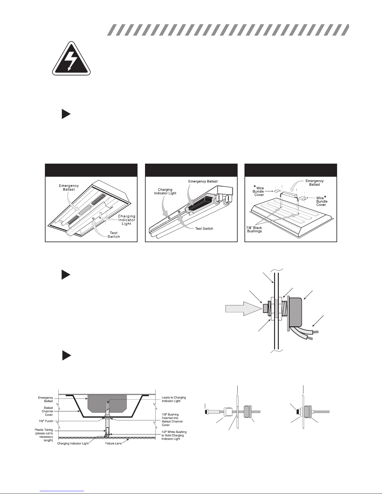
STEP #1
INSTALLING THE EMERGENCY BALLAST
> Disconnect AC power from the xture. Remove the ballast channel cover and install the emergency ballast
either in the ballast channel or on top of the xture.* Remote mounting distance must be less than half the
maximum remote mounting distance for the AC ballast. Consult AC ballast manufacturer before remote
installation.
> Depending on the type of xture in use install emergency ballast using one of the methods illustrated below.
Inside Ballast Channel
INSIDE BALLAST CHANNEL INSIDE STRIP FIXTURE ON TOP OF FIXTURE
* For installation on top of the xture, wire bundle covers (RMC-60) may be required by state or local codes. These covers are
available from the manufacturer as an accessory kit and must be ordered separately. Call your local distributor or the factory for complete
information.
STEP #2
INSTALLING THE TEST SWITCH
> Refer to the illustrations above and install the test switch
through the ballast channel cover of a troffer or through the
Inside Strip Fixture
Test Button
On Top of Fixture
Fixture
Hex Nut
side of a strip xture.
> Drill a 1/2" hole and install the switch as shown.
Push to Test
> Refer to the diagrams on page 4 and wire the test switch so
that it removes AC power from the unswitched hot line to the
emergency ballast.
Hex Nut
Test Switch
Leads
STEP #3
INSTALLING THE CHARGING INDICATOR LIGHT
> Install the CHARGING INDICATOR LIGHT as shown in the illustration on the next page so that it will be visible
after the xture is installed.
TROFFER STYLE FIXTURE
NOTE: After installing the charging indicator light and test switch, mark each with the appropriate label.
STRIP STYLE FIXTURE
* If violet and brown leads are detached, connect to
unit by matching wire colors.
2
 Loading...