

Philips AZT-9240 Service manual
PRODUCT FAMILY ULTRA – TUNER
Technical specification ...............................................1-1..1-2
Features ............................................................................1-2
Connections and controls..................................................1-3
Instruction For Use (excerpt)......................................1-4..1-6
Accessories .......................................................................1-7
Safety & Warnings.............................................................1-8
Service hints
Repair positions ............................................................2-1
Dismantling CD-door.....................................................2-1
Handling chip components............................................2-2
Service tools..................................................................2-2
Pin description of ICs ................................................3-1...3-3
Start-up procedure.............................................................3-4
Service Test Program................................................3-5...3-6
Blockdiagram.....................................................................3-7
Circuit diagrams
Supply part....................................................................4-1
CD part..........................................................................4-2
Control part ...................................................................4-3
Audio part......................................................................4-4
Tuner part (for orientation only).....................................4-5
Printed circuit board
Componentside view.....................................................4-6
Copperside view............................................................4-7
Tuner board (for orientation only)..................................4-8
Exploded view ...................................................................5-1
Mechanical partslist...........................................................5-2
Electrical partslist ......................................................6-1...6-4
CS 46 741
© 3103 785 25070
Published by PW 0110 Service Audio Printed in The Netherlands Subject to modification
Portable compact disc player
CLASS 1
LASER PRODUCT
TABLE OF CONTENTS
©
Copyright 2001 Philips Consumer Electronics B.V. Eindhoven, The Netherlands
All rights reserved. No part of this publication may be reproduced, stored in a retrieval
system or transmitted, in any form or by any means, electronic, mechanical, photocopying,
or otherwise without the prior permission of Philips.
AZT9240
all versions

1-1
CS 46 742
TECHNICAL SPECIFICATION
General
Dimensions (WxHxD) : 128x34x139.5mm
Weight without batteries : 220g
Laser
Output power : <5mW (3mW typ.)
Wavelength : 780nm
Shock resistance
+X/-X direction : ≥2.5g
+Y/-Y direction : ≥2.5g
+Z/-Z direction : ≥2.0g
Power supply modes
Battery lifetime
Battery level detection – CD mode
Battery level detection – Tuner mode
Current consumption
Charge section (not on all versions)
Charge current : 250mA ±10%
Charge time for 80% AY3362 : 4.0h nom.
Max. charge time (µ P controlled) : 7h
Temperature protection : 50°C ±5°C
Tuner (not on all versions)
Headphone out (measured with 16Ω load, DBB/ESP off)
Output power (THD=10%)
/17 version only : 2x6mW (+1/-3dB)
all other versions : 2x2.5mW (+1/-3dB)
Frequency response CD (1mW) : 100Hz-20kHz within 6dB
Frequency response AM (1mW) : 100Hz-1.5kHz within
6dB
Frequency response FM (1mW) : 100Hz-12.5kHz within
6dB
S/N ratio CD (unwght) : ≥78dB (81dB typ.)
S/N ratio CD (A-wght) : ≥82dB (84dB typ.)
S/N ratio AM (A-wght) : ≥40dB (45dB typ.)
S/N ratio FM (A-wght) : ≥45dB (55dB typ.)
THD+N CD (1kHz, 1mW) : ≤1% (0.2% typ.)
THD+N AM/FM (1kHz, 1mW) : ≤7% (2% typ.)
Channel crosstalk (1kHz, no load): ≤-24dB (-44dB typ.)
Channel unbalance (-40dB) : ≤5dB
Volume attenuation (1kHz) : ≥60dB
Dynamic Bass Boost DBB
EGATSBBD
esnopserycneuqerF
zHk36 zHk1 zHk01
1BBDBd6+ ± Bd2Bd0 ± Bd2Bd0 ± Bd2
2BBDBd9+ ± Bd2Bd0 ± Bd2Bd5+ ± Bd2
MF MA
egnargninuTzHM801-5.78
zHk2061-135
71/rofzHk0071-035
FIzHM7.01zHk054
ytivitisneS
%03=m,N/SBd62
tniopgnitimilBd3-
≤ ).pytfBd51(fBd22
≤ ).pytfBd51(fBd62
≤ ).pytm/Vm3(m/Vm5
dirgycneuqerF
zHk001
71/rofzHk05
zHk9
71/rofzHk01
noitrotsiD
≤ ).pyt%2(%7
,Vm1=fr ∆ zHk57=f
≤ ).pyt%2(%7
%08=m,Vm1=fr
oitarnoitcejeregamI ≥ ).pytBd52(Bd02 ≥ ).pytBd04(Bd82
EDOMNOITAREPO
)V5.4(YLPPUSNI-CD )V52.2(YLPPUS.TTAB
FFOPSE NOPSE FFOPSE NOPSE
edomyalPDC.pytAm011.pytAm001.pytAm031.pytAm021
edompmuJDC.pytAm022.pytAm022.pytAm003.pytAm004
edomRENUT.pytAm03.pytAm03
yb-dnatS
)egrahcer.lcxe(
.pytAm51053 µ .pytA
LEVELNOITCETED seirettabyramirP seirettabelbagrahceR
ytpmeyrettaB
V0.2
Vm05-/001+
V0.2
Vm05-/001+
1kaewyrettaB
+levelytpmeyrettab
V7.0 ± Vm001
+levelytpmeyrettab
V5.0 ± Vm001
2kaewyrettaB
+levelytpmeyrettab
V54.0 ± Vm001
+levelytpmeyrettab
V53.0 ± Vm001
3kaewyrettaB
+levelytpmeyrettab
V2.0 ± Vm001
+levelytpmeyrettab
V2.0 ± Vm001
LEVELNOITCETED seirettabyramirP seirettabelbagrahceR
ytpmeyrettaB
V8.1
Vm05-/001+
V8.1
Vm05-/001+
1kaewyrettaB
+levelytpmeyrettab
V57.0 ± Vm001
+levelytpmeyrettab
V7.0 ± Vm001
2kaewyrettaB
+levelytpmeyrettab
V54.0 ± Vm001
+levelytpmeyrettab
V5.0 ± Vm001
3kaewyrettaB
+levelytpmeyrettab
V3.0 ± Vm001
+levelytpmeyrettab
V3.0 ± Vm001
EPYTYRETTAB
EDOMDC
FFOPSE
EDOMDC
NOPSE
RENUT
EDOM
seirettabyramirP
6RLx2
≥ h21
).pyth81(
≥ h21
).pyth81(
≥ h05
).pyth07(
seirettabelbagrahceR
)hAm0021(2633YA
≥ h7
).pyth01(
≥ h7
).pyth01(
≥ h52
).pyth53(
EDOMYLPPUS
egnaregatloV
DC renuT
tekcosNI-CDV0.6-5.2
seirettabyramirP
6RLx2
V6.3-6.1V6.3-9.1
seirettabelbagrahceR
)hAm0021(2633YA
V6.3-6.1V6.3-9.1
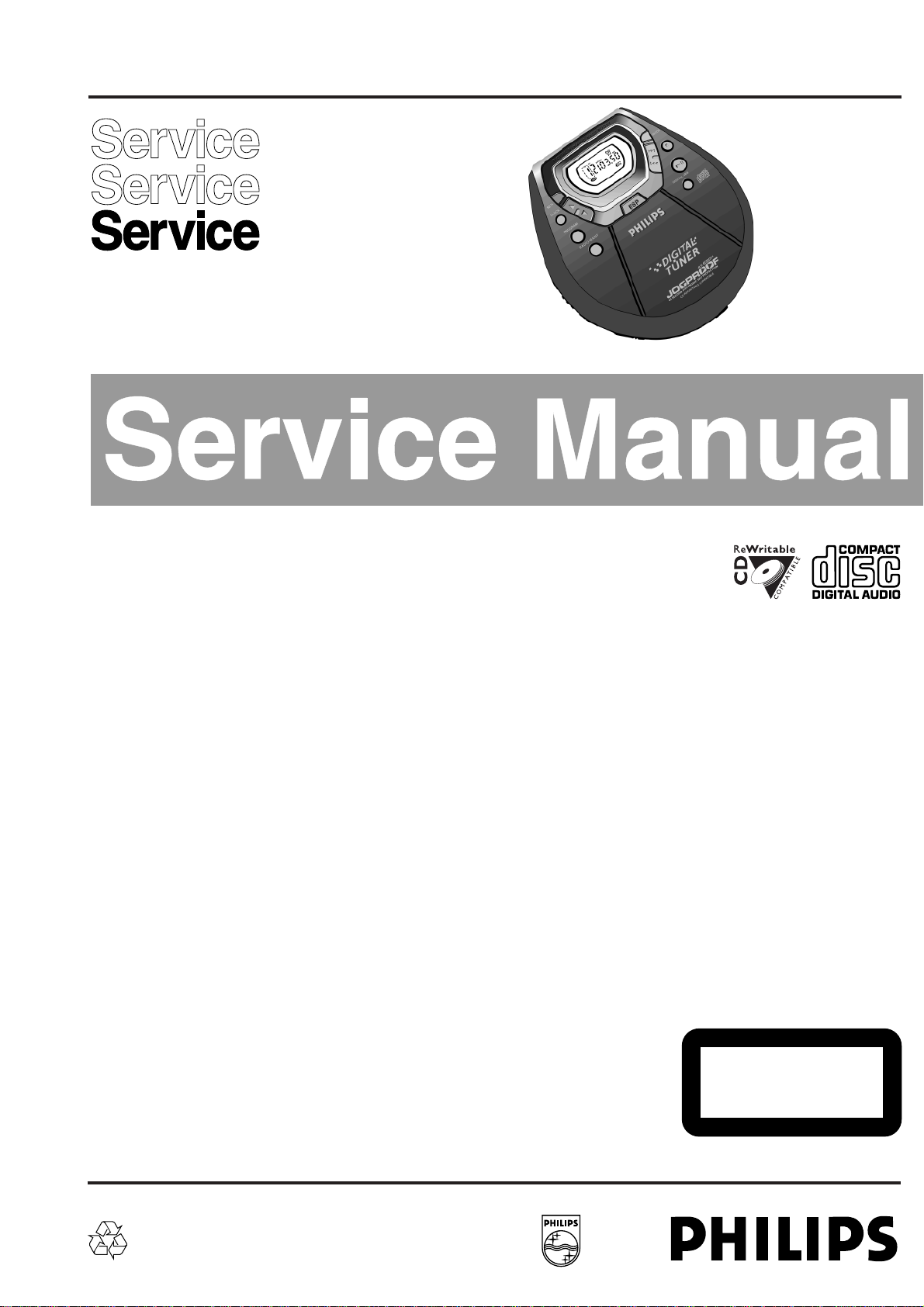
Measurement setup CD
Use Audio Signal disc SBC429 4822 397 30184
Measurement setup FM
Use bandpass filter to eliminate hum (50Hz, 100Hz) and
disturbance from pilottone (19kHz, 38kHz).
Measurement setup AM
To avoid admospheric interference all AM measurements
have to be carried out in a Farraday’s cage.
Use bandpass filter (or at least a high pass filter with 250Hz)
to eliminate hum (50Hz, 100Hz).
Bandpass
250Hz-15kHz
e.g. 7122 707 48001
LF Voltmeter
e.g. PM2534
DUT
S/N and distortion meter
e.g. Sound Technology ST1700B
Frame aerial
e.g. 7122 707 89001
RF Generator
e.g. PM5326
Ri=50Ω
Bandpass
250Hz-15kHz
e.g. 7122 707 48001
LF Voltmeter
e.g. PM2534
DUT
RF Generator
e.g. PM5326
S/N and distortion meter
e.g. Sound Technology ST1700B
Ri=50Ω
Low pass filterDUT S/N and distortion meter
L
R
i.e. Sennheiser UPM550
with FF-filter
Level meter
i.e. Sound Technology ST1700Bi.e. 4822 395 30204
22kHz
13th order
1-2
CS 46 743
FEATURE OVERVIEW
ELBATROP-DCFOSERUTAEF
”RENUT-ARTLU“YLIMAFTCUDORP
0429TZA
)snoisrevlla(
WS/WM/MFRENUT
● / ● –/
YTILIBITAPMOCELBATIRWER-DC
●
NOITCETORPPIKSCINORTCELE
s54
EZISMARDPSE
tibM61
NOITCNUFEMUSER/DLOH
● / ●
SEGATSBBD
2
KCABDEEFCITSUOCA
●
YROMEMMARGORP
99
HMiN/dCiNNOITCNUFEGRAHCER
● / ●
DERAPERPLORTNOCETOMERDROC
–
THGILKCABYALPSID
–
TUPTUOLATIGID/ENIL
–/–
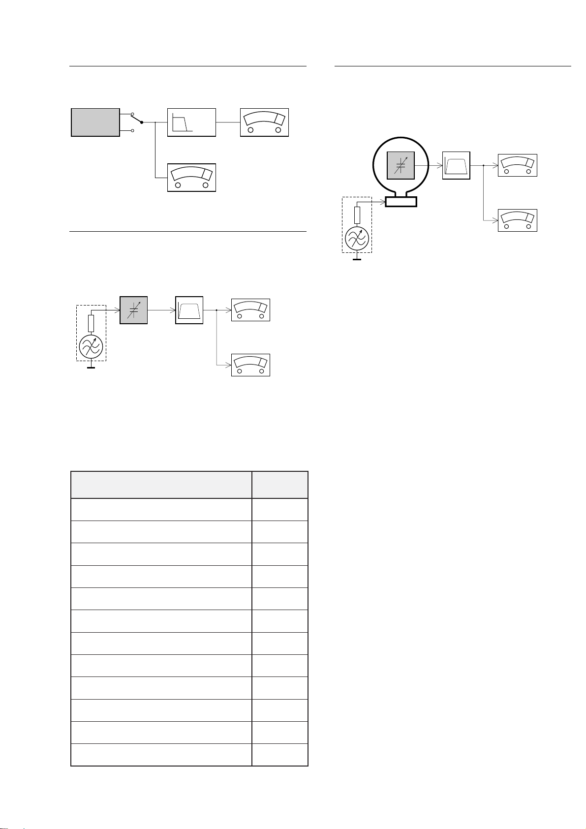
CONNECTIONS AND CONTROLS
0
O
P
EN
O
F
F
•
R
E
S
U
M
E
•
H
O
L
D
L
I
N
E
O
U
T
/
V
O
L
.
E
SP
P
R
O
GR
A
M
C
L
O
C
K
R
A
D
I
O
·B
A
N
D
DIG
ITAL D
BB
1
2
3
47
8
0
$
%
(
5
6
9
!
@
#
S
E
T
·
·M
O
DE
^
*
&
1-3
CS 46 744
1DIGITAL DBB....DIGITAL DYNAMIC BASS BOOST
switches the bass enhancement on and
off
22;......................switches the player on, starts or pauses
CD play
39........................stops CD play, clears a CD program or
switches the player off
4§.......................skips and searches CD tracks forwards,
selects the next preset radio station
∞.......................skips and searches CD tracks
backwards, selects the previous preset
radio station
5MODE ...............selects the different playing possibilities:
shuffle, shuffle repeat all, repeat, repeat
all and SCAN
6 ..........................display
73 .......................tunes to radio stations upwards, sets the
time upwards
4 .......................tunes to radio stations downwards, sets
the time downwards
8SET...................activates / confirms the current time
setting, activates / confirms the alarm
time setting
9CLOCK..............switches to clock or alarm clock display
0PROGRAM........programs CD tracks and radio stations,
reviews the program
!RADIO·BAND ....switches the radio on, selects a
waveband
@RESUME...........stores the last position of a CD track
played
HOLD................locks all buttons
OFF...................switches RESUME and HOLD off
#LINE OUT/p ......3.5 mm headphone socket, socket to
connect the player to another analogue
audio input of an additional appliance,
remote control socket
$VOL E ............adjusts the volume
%OPEN 2 ............opens the CD lid
^4.5V DC.............socket for external power supply
& ..........................belt clip holder
* ..........................typeplate
(ESP...................ELECTRONIC SKIP PROTECTION
ensures continuous CD playback
regardless of vibrations and shocks,
switches the alarm function on and off
INSTRUCTION FOR USE (excerpt)
• FM: The headphone wire is used as FM antenna.
If necessary move it for optimum reception.
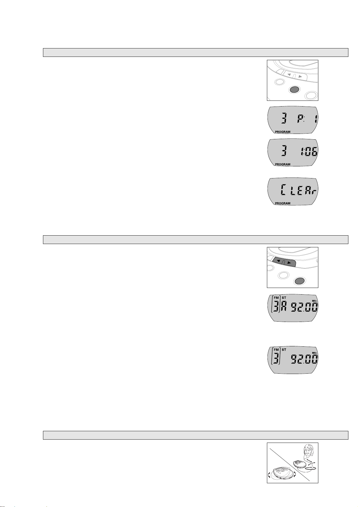
• MW: The internal MW antenna is directed by turning the player.
Antennas
K
You can tune to any FM or MW station automatically or manually.
Stereo stations are indicated by
ST.
1 Press RADIO·BAND to switch the radio on.
2 Press RADIO·BAND if necessary repeatedly to select the desired waveband.
y FM 1, FM 2, FM 3, FM 4 or MW is shown.
Tuning to radio stations automatically
1 Keep 3 or 4 pressed for at least 1 second.
y The radio tunes to a station with sufficient strength and radio play starts.
A (for “automatic search”) and the current waveband and frequency are displayed.
2 Repeat searching until you find the desired radio station.
Tuning to radio stations manually
1 Keep 3 or 4 pressed.
2 Release 3 or 4, then briefly press 3 or 4 again when you are close to the desired
frequency.
3 Briefly press 3 or 4 repeatedly until you reach the desired frequency.
y Radio play starts. The current waveband and frequency are displayed.
• To switch from radio play to CD play press 2;.
• Press 9 to switch the radio off.
Note: In case of interferences in stereo mode press ·
MODE
to switch to mono.
Radio play
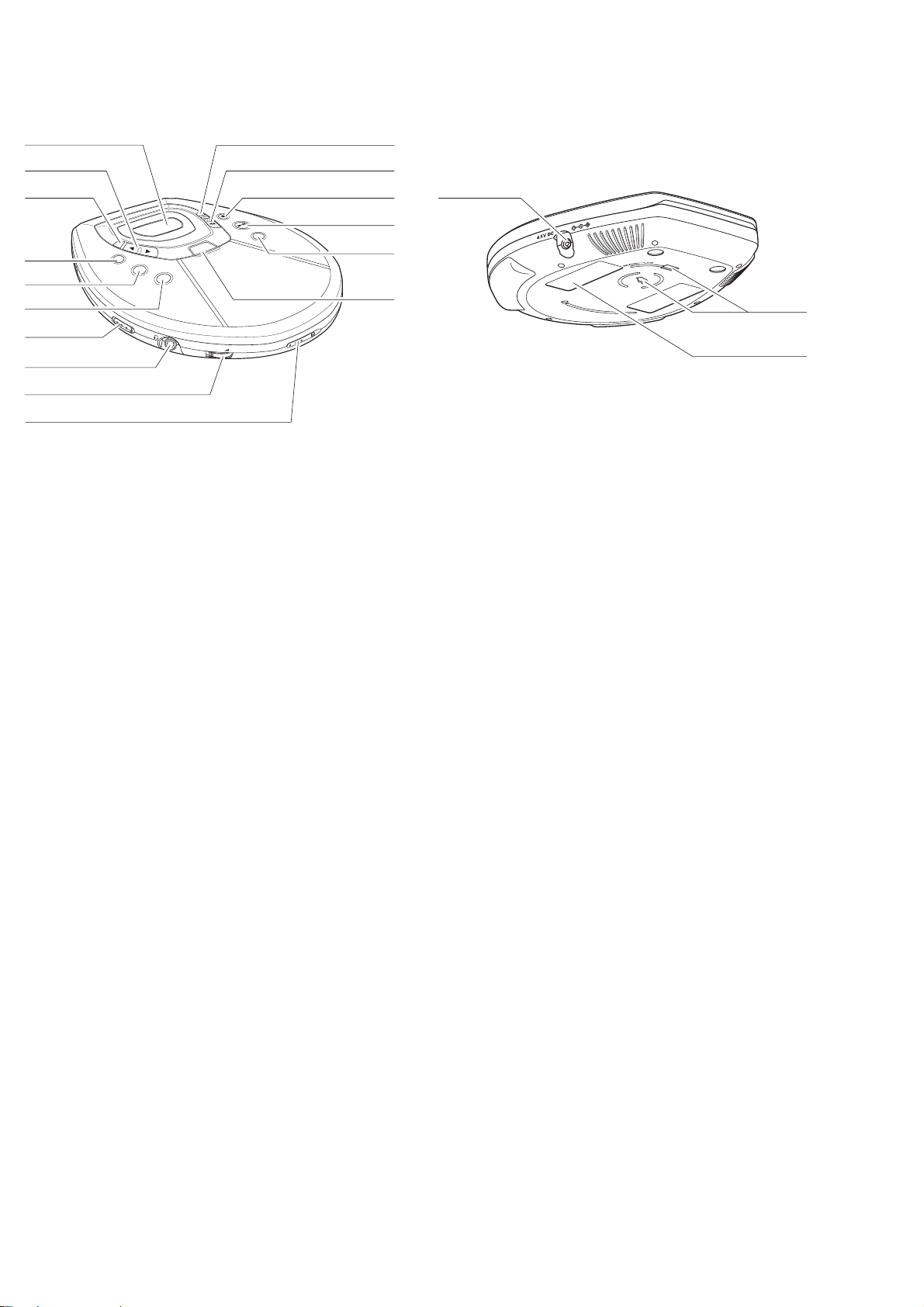
You can select up to 99 tracks and store them in memory in a desired sequence.
Any track can be stored more than once.
1 While playback is stopped, select a track with ∞ or §.
2 Press PROGRAM to store the track.
y PROGRAM lights up; the track number programmed and P with the total number of
stored tracks are displayed.
3 Select and store all desired tracks in this way.
4 Press 2; to start playback of your selected tracks.
y PROGRAM is shown and playback starts.
• You can review the program by pressing PROGRAM for more than 2 seconds.
y The display shows all stored tracks in sequence.
Notes: – If you press
PROGRAM
and there is no track selected,
SELECt
is displayed.
– If you try to store more than 99 tracks,
FULL
is displayed.
Clearing the program
1 If necessary, press 9 to stop playback.
2 Press 9 to clear the program.
y CLEAr is displayed once, PROGRAM goes off and the program is cleared.
Notes: The program will also be cleared if you
– interrupt the power supply or
– open the CD lid.
Programming track numbers
1-4
CS 46 745
T·
E
S
CK
O
CL
M
RA
G
PRO
RADIO·BAND
·
PROGRAM
RADIO·BAND
E
D
O
M
N
E
P
O
0
OPEN
0
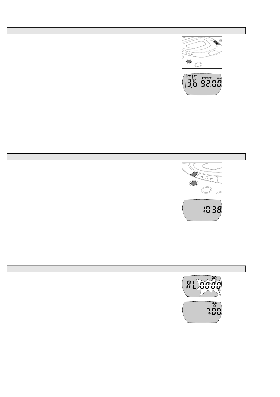
Provided the current time has been set, your player can be used as an alarm clock.
1 Keep SET· pressed for approximately 2 seconds, then briefly press SET· again.
y AL is displayed and the alarm clock digits 00:00 flash.
2 Press 3 or 4 repeatedly within 5 seconds to set the alarm time.
y is shown and the alarm time is displayed.
3 Press SET· twice or do not press any key for 5 seconds.
y The alarm time is set and the alarm display goes off.
• To switch to the alarm clock display during CD or tuner play, press CLOCK twice.
y is shown and the alarm time is displayed for 5 seconds.
Alarm time setting
PROGRAM
C
LO
CK
DIO·B
A
ND
Your player has a built-in clock. However CD or tuner play is not conditional upon the
time setting.
1 Keep SET· pressed for approximately 2 seconds.
y The clock digits OO:OO flash.
2 Keep 3 or 4 pressed, then briefly press 3 or 4 again repeatedly within 5 seconds to
set the current time.
y The current time is displayed.
3 Press SET· three times or do not press any key for 5 seconds.
y The current time is set and the time display goes off.
• To switch to the clock display during CD or tuner play, press CLOCK.
y The current time is displayed for 5 seconds.
Notes: – When the player is supplied by batteries do not remove the batteries during
radio play, otherwise time settings will be lost and will have to be readjusted.
– If the power supply is interrupted for longer than 1 minute, all time settings
will be lost and will have to be readjusted.
Time setting
You can store up to 30 radio stations.
1 Tune to a desired radio station and press PROGRAM.
2 Press ∞ or § if necessary repeatedly to select the number that should be assigned to
this radio station.
3 Press PROGRAM while
PRESET is blinking to confirm the storing.
y PRESET, the waveband, the frequency and the preset number of the stored station
are displayed.
4 Store all desired stations this way.
Note: Already stored stations can be recognized by the indicator
PRESET
and the preset
number.
Tuning to a stored radio station
1 Select the waveband.
2 Press ∞ or § if necessary repeatedly to select the preset number of the desired radio
station.
y Radio play starts. PRESET, the waveband, the frequency and the preset number of
the stored station are displayed.
Storing radio stations
1-5
CS 46 746
PROGRAM
RADIO ·BAN
E
OD
·M
ESP
D
SET·

Troubleshooting
1-6
CS 46 747
MELBORP ESUACELBISSOP NOITULOS
tratstonseod
CSIdFn
noitacidni
CSIdon
noitacidni
dloH
skcartspiksDC
dabrodnuosoN
ytilauqdnuos
sgnittesemit
seirettaB
yltcerrocnidetresniseirettaB
ytpmeeraseirettaBseirettabehtegnahC
kcabyalp,rewopoN
esurac-nI
ffo
ytriderasniptcatnoChtolcahtiwmehtnaelC
retpadasniaM
noitcennocesooL
sinoitinginehwderewoptonsirethgiletteragiC
ylreporpdedrocertonsi)R-DC(WR-DC
ytridrodehctarcsyldabsiDCehTDCehtnaelcroecalpeR
detresniyltcerrocnirotonsiDC sdrawpulebal,DCatresnI
pudemaetssisnelresalehT deraelcsahsnelehtlitnutiaW
detavitcasiDLOHdloHetavitcaeD
onro/dnanoitacidni
slortnocotnoitcaer
senohp
esurac-nI
noitpeceroidarrooP
krowtonseodmralA detavitcatonsimrala/testonsiemitmralA mralaehtetavitca/emitmralaehtteS
fossol,snoitcnuflaM
egrahcsidcitatsortcelE
ytridrodegamadsiDCehTDCehtnaelcroecalpeR
ELFFUHS,EMUSER ro MARGORP evitcasiffoMARGORProELFFUHS,EMUSERhctiwS
detavitcasiESUAPsserP ;2
snoitcennocytridrognorw,esooL snoitcennocnaelcdnakcehC
detsujdatonsiemuloVemulovehttsujdA
elibomevitcafoytinicivoteudsnoitcnuflaM
reyalpehtraensdleifcitengamgnortS snoitcennocronoitisops'reyalpehtegnahC
yltcerrocnidetresnisiretpadaettessaC
wol/hgihootsiracehtedisnierutarepmeT erutarepmetehtottsujdareyalpehtteL
ytridsitekcosrethgiletteragiC tekcosrethgiletteragicehtnaelC
ettessacracehtfonoitceridkcabyalpgnorW
erutaefesreverotuas'reyalp
langisoidarkaeW noitpecermumitporofannetnaehttceriD
ekiltnempiuqecirtceleybdesuacecnerefretnI
.ctesenigne,sretupmoc,sVT
seirettabkaewhtiwnoitarepodeunitnoC sgnittestsujdaer,seirettabegnahC
yltcerrocseirettabehttresnI
ylerucesretpadaehttcenoC
seirettabtresnironoitinginohctiwS
etelpmocotredroceRDCehtnoEZILANIFesU
gnidrocereht
ekatroylppusrewopmorftesehttcennocsiD
sdnoceswefarofseirettabehttuo
elibomevitcamorfyawareyalpehtpeeK
senohp
yltcerrocretpadaettessacehttresnI
noitceridesreverotuaehtegnahC
tnempiuqecirtcelemorfyawareyalpehtpeeK

ACCESSORIES
ELBATROP-DCROFSEIROSSECCA
”RENUT-ARTLU“YLIMAFTCUDORP
0429TZA
00/ 10/ 71/ p71/ 91/
00/0713TYA rotpadACD/CA017238110413X
20/0713TYA rotpadACD/CA027238110413X
71/0713TYA rotpadACD/CA057238110413XX
91/0713TYA rotpadACD/CAreilppuslacolX
00/2633YA HMiNyrettabelbagrahceR021488033013XXX
4643YA mm5.3(DROCIFIH → )gulp-L,hcnic188110232284 OOOOO
00/1053YA ettessaCrotpadAraC950017932284 OOOOO
00/5453YA retrevnoCCD/CDraC330019122284 OOOOO
77/545EHCBS )gulp-L(enohpraE862000012809XXX
77/053LHCBS )gulp-L(enohpdaeH532000012809XX
PILC-TLEB 052074033013 XXOOX
elbaliavalanoitpo...O,tesehthtiwdeilppus...X
1-7
CS 46 748
SAFETY & WARNINGS
© WARNING
All ICs and many other semiconductors are susceptible to
electrostatic discharges (ESD). Careless handling during
repair can reduce life drastically.
When repairing, make sure that you are connected with the
same potential as the mass of the set via a wristband with
resistance. Keep components and tools at this potential.
f ATTENTION
Tous les IC et beaucoup d´autres semi-conducteurs sont
sensibles aux décharges statiques (ESD). Leur longévite
pourrait être considérablement écourtée par le fait qu´aucune
précaution nést prise à leur manipulation.
Lors de réparations, s´assurer de bien être relié au même
potentiel que la masse de l´appareil et enfileer le bracelet
serti d´une résistance de sécurité.
Veiller à ce que les composants ainsi que les outils que l´on
utilise soient également à ce potentiel.
d WARNUNG
Alle ICs und viele andere Halbleiter sind empfindlich
gegenüber elektrostatischen Entladungen (ESD).
Unsorgfältige Behandlung im Reparaturfall kann die
Lebensdauer drastisch reduzieren.
Sorgen Sie dafür, daß Sie im Reparaturfall über ein Pulsarmband mit Widerstand mit dem Massepotential des
Gerätes verbunden sind.
Halten Sie Bauteile und Hilfsmittel ebenfalls auf diesem
Potential.
ñ WAARSCHUWING
Alle IC´s en vele andere halfgeleiders zijn gevoelig voor
electrostatische ontladingen (ESD).
Onzorgvuldig behandelen tijdens reparatie kan de levensduur
drastisch doen vermindern. Zorg ervoor dat u tijdens reparatie
via een polsband met weerstand verbonden bent met hetzelfde
potentiaal als de massa van het apparaat.
Houd componenten en hulpmiddelen ook op ditzelfde potentiaal.
i AVVERTIMENTO
Tutti IC e parecchi semi-conduttori sono sensibili alle scariche
statiche (ESD).
La loro longevità potrebbe essere fortemente ridatta in caso di
non osservazione della più grande cauzione alla loro
manipolazione. Durante le riparationi occorre quindi essere
collegato allo stesso potenziale che quello della massa
delápparecchio tramite un braccialetto a resistenza.
Assicurarsi che i componenti e anche gli utensili con quali si
lavora siano anche a questo potenziale.
©
Safety regulations require that the set be restored to its
original condition and that parts which are identical with
those specified be used.
Safety components are marked by the symbol
i
Le norme di sicurezza estigono che l´apparecchio venga
rimesso nelle condizioni originali e che siano utilizzati i
pezzi di ricambiago identici a quelli specificati.
Componenty di sicurezza sono marcati con
ñ
Veiligheidsbepalingen vereisen, dat het apparaat in zijn
oorspronkeliijke toestand wordt teruggebracht en dat
onderdelen, identiek aan de gespecificeerde, worden toegepast.
De Veiligheidsonderdelen zijn aangeduid met het symbool
s Varning !
Osynlig laserstrålning när apparaten är öppnad och
spärren är urkopplad. Betrakta ej strålen.
∂ Advarsel !
Usynlig laserstråling ved åbning når sikkerhedsafbrydere
er ude af funktion. Undgå udsaettelse for stråling.
ß Varoitus !
Avatussa laitteessa ja suojalukituksen ohitettaessa olet alttiina
näkymättömälle laserisäteilylle. Älä katso säteeseen !
f
"Pour votre sécurite, ces documents doivent être utilisés par
des spécialistes agréés, seuls habilités à réparer votre
appareil en panne".
ESD
SAFETY
d
Bei jeder Reparatur sind die geltenden Sicherheitsvorschriften zu beachten. Der Originalzustand des Gerätes
darf nicht verändert werden. Für Reparaturen sind Originalersatzteile zu verwenden.
Sicherheitsbauteile sind durch das Symbol markiert.
f
Les normes de sécurité exigent que l`appareil soit remis
à l`état d`origine et que soient utilisées les pièces de
rechange identiques à celles spécifiées.
Les composants de sécurité sont marqués
CLASS 1
LASER PRODUCT
©
DANGER: Invisible laser radiation when open.
©
After servicing and before returning the set to customer
perform a leakage current measurement test from all
exposed metal parts to earth ground, to assure no
shock hazard exists.
The leakage current must not exceed 0.5mA.
AVOID DIRECT EXPOSURE TO BEAM.
©
AVAILABLE ESD PROTECTION EQUIPMENT :
anti-static table mat large 1200x650x1.25mm 4822 466 10953
small 600x650x1.25mm 4822 466 10958
anti-static wristband 4822 395 10223
connection box (3 press stud connections, 1MΩ) 4822 320 11307
extendible cable (2m, 2MΩ, to connect wristband to connection box) 4822 320 11305
connecting cable (3m, 2MΩ, to connect table mat to connection box) 4822 320 11306
earth cable (1MΩ, to connect any product to mat or to connection box) 4822 320 11308
KIT ESD3 (combining all 6 prior products - small table mat) 4822 310 10671
wristband tester 4822 344 13999
1-8
CS 46 749
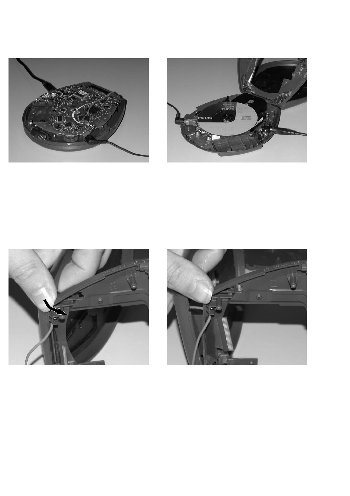
SERVICE HINTS
REPAIR POSITION COPPERSIDE
To get access to the copperside of the
printed board assembly proceed as follows:
1. Remove the bottom screws (6x)
2. Lift the bottom-cabinet
3. Supply the unit via external DC-socket
4. Take care that the door switch is closed during
measurements
DISMANTLING THE CD-DOOR
To dismantle the CD-door proceed as follows:
1. Dismantle bottom and printed board/drive assembly
2. Disconnect membrane keyboard
(flex-foil connector on copperside of printed board)
3. Bend the cabinet rightwards downwards as indicated in
the picture above.
REPAIR POSITION COMPONENTSIDE
To get access to the componentside of the
printed board assembly proceed as follows:
1. Remove the bottom screws (6x)
2. Open the CD-door
3. Lift the top-cabinet and put it backwards on the table
4. Supply the unit via the external DC-socket
5. Take care that the door switch is closed during
measurements
Remark: Do not use screwdrivers or tools like that.
Sharp edges could damage hinge or cabinet part.
2-1
CS 46 750
 Loading...