

Philips AZ-5737 Service Manual
DVD CD Soundmachine
AZ5737
all versions
TABLE OF CONTENTS
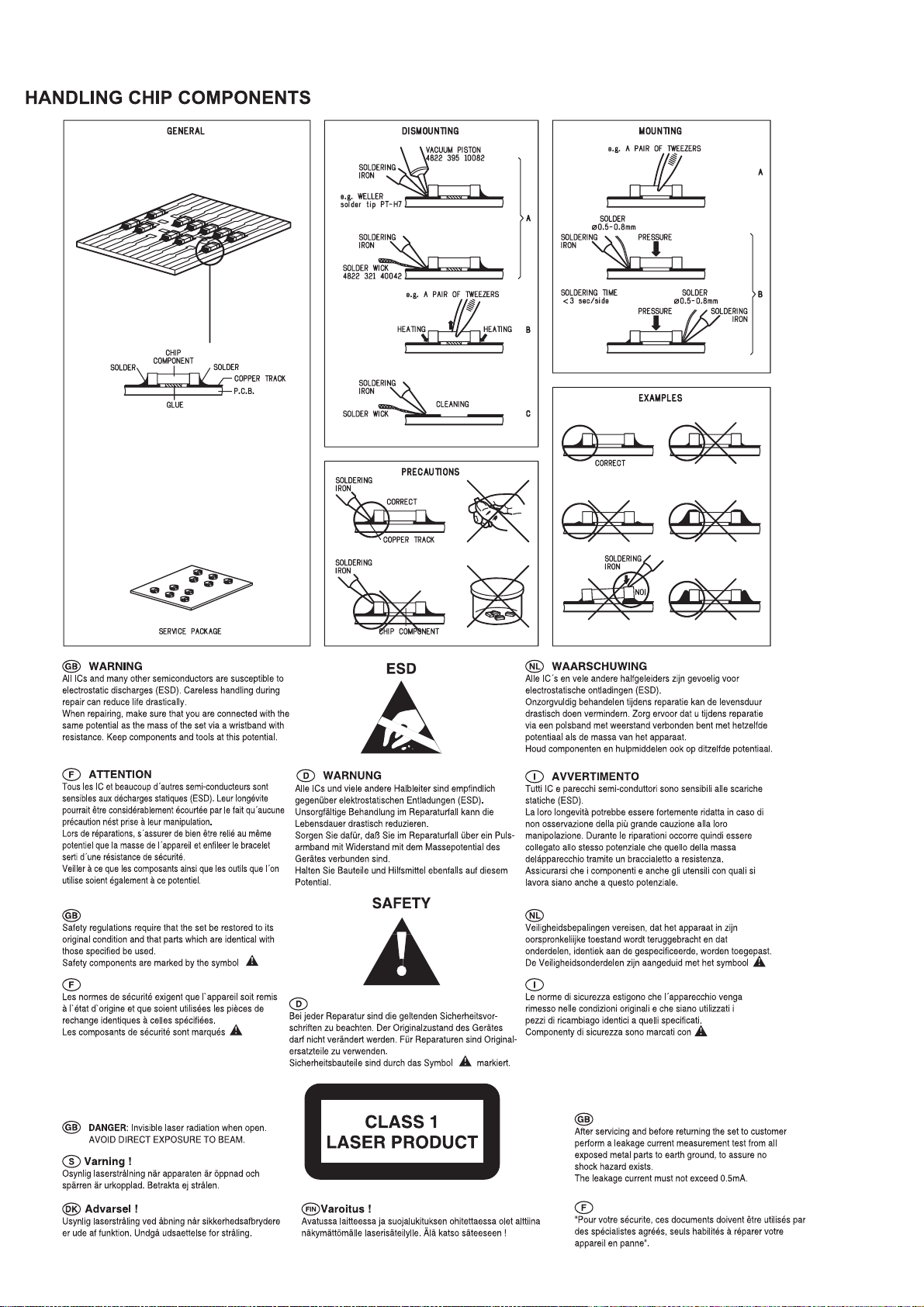
Handling chip components ...........................................................1-1
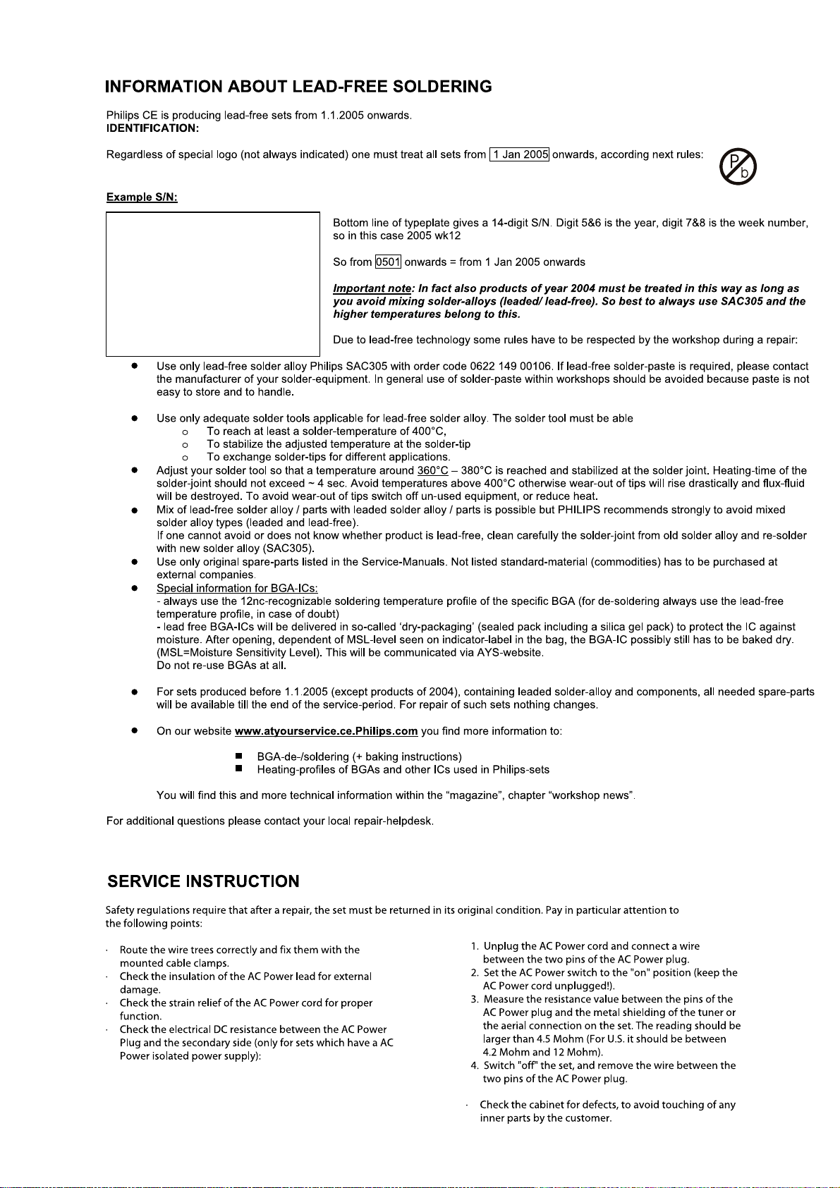
Leadfree and safety information ....................................................1-2
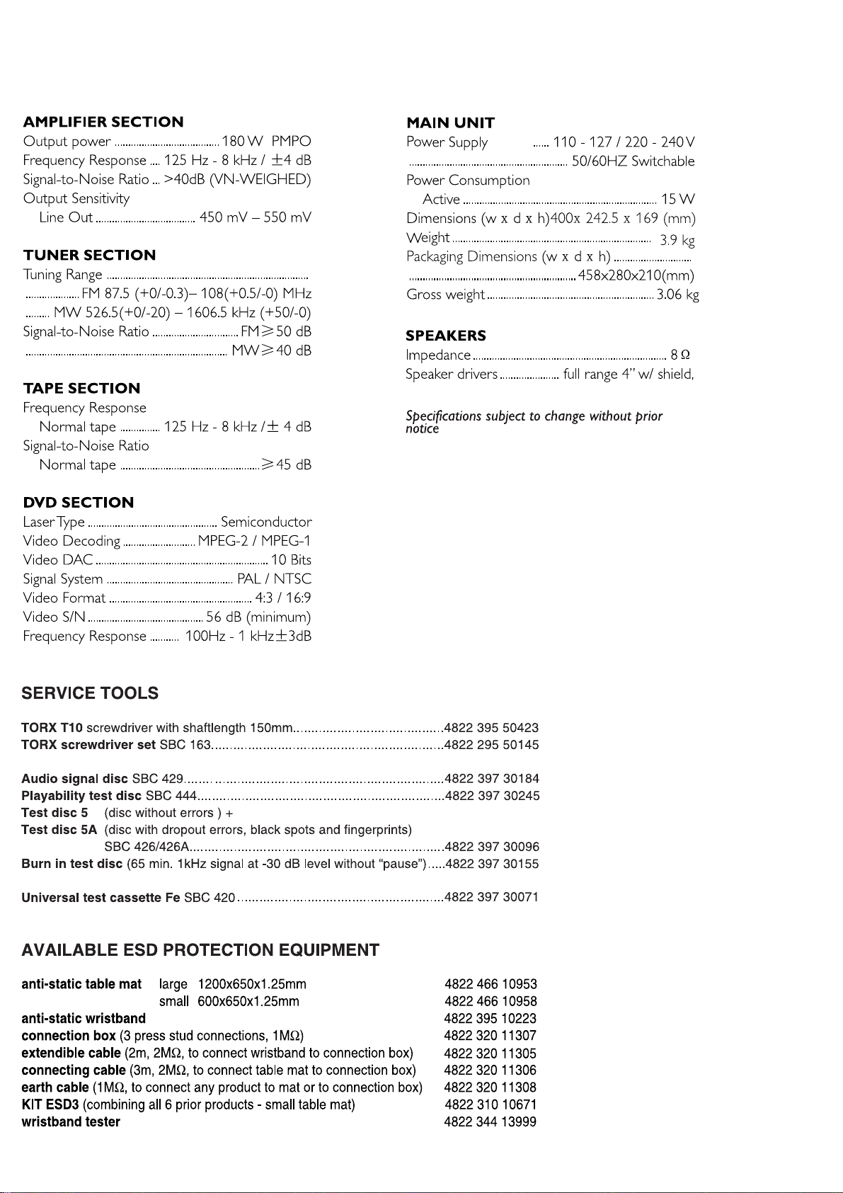
Technical specification ...................................................................2-1
Service tools .................................................................................2-1
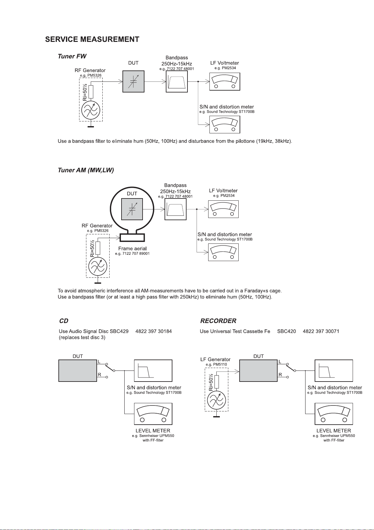
Service measurement setup ..........................................................2-2
Connections and controls ......................................................3-1...3-3
Dismantling instructions ........................................................4-1...4-2
Software vesion checking and upgrading ......................................5-1
Block diagram ................................................................................6-1
Wiring diagram .............................................................................7-1
Control Board
circuit diagram ..........................................................................8-1
layout diagram ..........................................................................8-2
©
Copyright 2006 Philips Consumer Electronics B.V. Eindhoven, The Netherlands
All rights reserved. No part of this publication may be reproduced, stored in a retrieval
system or transmitted, in any form or by any means, electronic, mechanical, photocopying,
or otherwise without the prior permission of Philips.
Tuner Board
circuit diagram ..........................................................................9-1
layout diagram .........................................................................9-2
Tape Board
circuit diagram. .......................................................................10-1
layout diagram ........................................................................10-2
Main Board
circuit diagram. .............................................................11-1...11-4
layout diagram .............................................................. 11-5...11-6
Exploded view diagram ...............................................................12-1
Mechanical partslist .....................................................................12-2
Electrical partslist...............................................................13-1...13-4
Published by LX 0625 Service Audio Subject to modification
Version 1.1
© 3141 785 31211
1 - 1
1 - 2
TECHNICAL SPECIFICATIONS
2 - 1
-/98
2 - 2
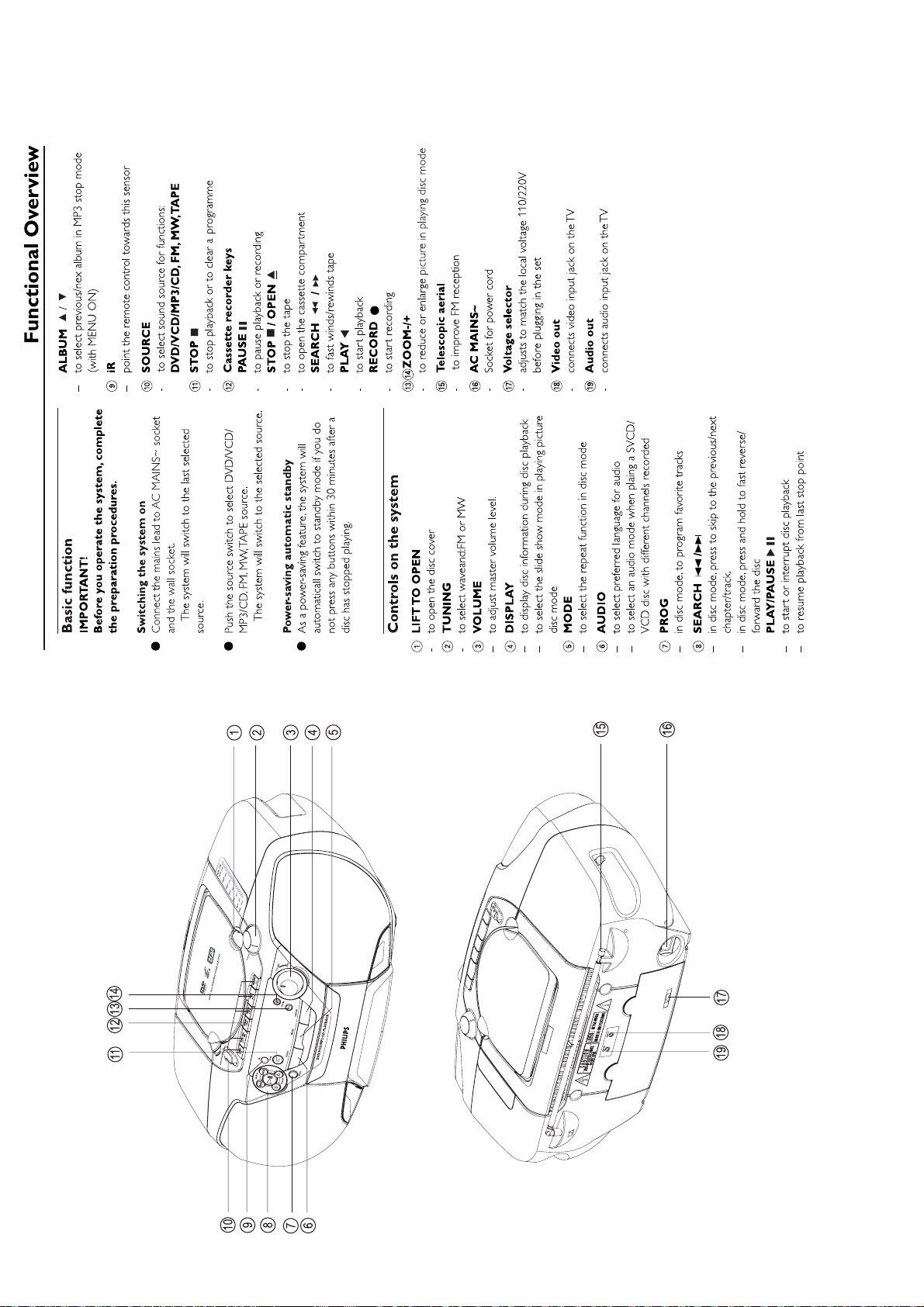
CONNECTION AND CONTROLS
3 - 1
CONNECTION AND CONTROLS
3 - 2
CONNECTION AND CONTROLS
3 - 3
4-1
4-1
DISASSEMBLY INSTRUCTIONS
Dismantling of the Front Panel & Control board Assembly
1) Loosen 4 screws at back panel "A" & "B" and 2 screws at
bottom side "C" to remove the front panel assembly as
shown in figure 1, 2 & 3.
A
Figure 1
B
Figure 2
4) Loosen 4 screws "D" in figure 6 and press the bracket support in figure 7 to remove the control board assembly .
- 2 screws each on the left & right side
- each bracket support on the left & right side
press
D
Figure 6
Figure 7
C
2) Lift up the tuning button with a sharp tool as shown in
figure 4.
5) Loosen 8 screws "E" as shown in figure 8 to remove the control board assembly.
Figure 3
+
3) Press the "Open/Close" button to open the DVD loader
door as shown in figure 5.
press
Figure 8
Figure 4
Figure 5

4-24-2
Dismantling of the Tuner Board
1) Loosen 1 screw " F " which location close to tuning button
as shown in figure 9 .
2) Loosen 1 screw " G " inside the back panel as shown in
figure 10.
F
3) Loosen 1 screw "H" ground wire inside back panel as
shown in figure 11.
4) Loosen 2 screws "I" at tuner board assembly as shown in
figure 12.
G
Dismantling of the Tape Deck &Tape Board
1) Loosen 2 screw " K " and remove the support sheet as shown in figure 13.
2) Loosen 4 screw " J " at tape deck as shown in figure 14.
3) Loosen 1 screw " L " to remove the tape board assembly as shown in figure 15.
K
Figure 9
Figure 10
Figure 13
I
J
L
Figure 11
Figure 12
Figure 14
Figure 15
 Loading...