

Philips AZ-5140 Service Manual
VCD MP3 CD Soundmachine
AZ5140
all versions
TABLE OF CONTENTS
Handling Chip Components and Safety ..........................1 - 1
Information about lead-free soldering..............................1.-.2
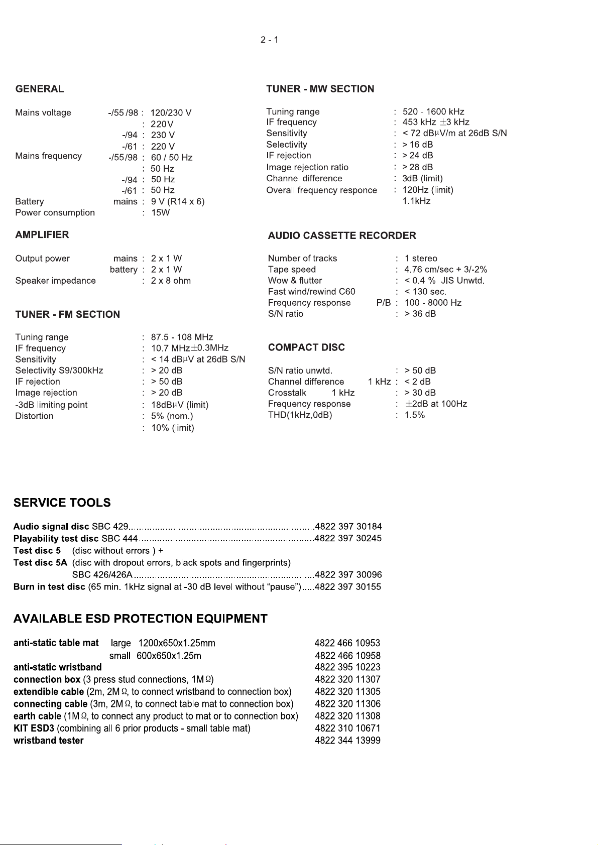
Technical Specification & Service tools...........................2 - 1
Service Measurement......................................................2 - 2
Connections and controls....................................3 - 1 to 3 - 3
Disassembly Diagram......................................................4 - 1
Block Diagram .................................................................5 - 1
Wiring Diagram................................................................6 - 1
Tuner Board
Circuit Diagram........................................................7 - 1
Layout Diagram.......................................................7 - 2
LCD Board
Circuit Diagram........................................................8 - 1
Layout Diagram.......................................................8 - 2
VIDEO CD
Main Board
Circuit Diagram (AMP part).....................................9 - 1
Circuit Diagram (Tuner part)....................................9 - 2
Layout Diagram...........................................9 - 3 to 9 - 4
Tape Board
Circuit Diagram......................................................10 - 1
Layout Diagram.....................................................10 - 2
Exploded Views Diagram
Cabinet .................................................................11 - 1
Mechanical Partslist.......................................................12 - 1
Electrical Partslist............................................12 - 2 to 12 - 6
Revision list....................................................................13 - 1
©
Copyright 2006 Philips Consumer Electronics B.V. Eindhoven, The Netherlands
All rights reserved. No part of this publication may be reproduced, stored in a r
system or transmitted, in any form or by any means, electronic, mechanical, pho
or otherwise without the prior permission of Philips.
Published by LX 0638 Service Audio Printed in The Netherlands Subject to modification
etrieval
tocopying,
Version1.22
CLASS 1
LASER PRODUCT
© 3141 785 30812
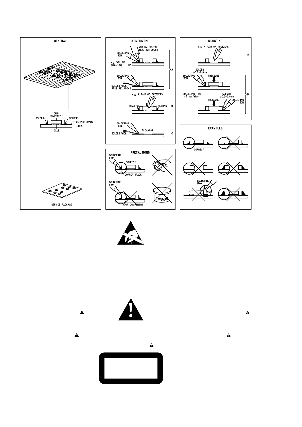
HANDLING CHIP
COMPONENTS
©
WARNING
All ICs and many other semiconductors are susceptible to
electrostatic discharges (ESD). Careless handling during
repair can reduce life drastically.
When repairing, make sure that you are connected with the
same potential as the mass of the set via a wristband with
resistance. Keep components and tools at this potential.
f
ATTENTION
Tous les IC et beaucoup d´autres semi-conducteurs sont
sensibles aux décharges statiques (ESD). Leur longévite
pourrait être considérablement écourtée par le fait qu´aucune
précaution nést prise à leur manipulation.
Lors de réparations, s´assurer de bien être relié au même
potentiel que la masse de l´appareil et enfileer le bracelet
serti d´une résistance de sécurité.
Veiller à ce que les composants ainsi que les outils que l´on
utilise soient également à ce potentiel.
d
WARNUNG
Alle ICs und viele andere Halbleiter sind empfindlich
gegenüber elektrostatischen Entladungen (ESD).
Unsorgfältige Behandlung im Reparaturfall kann die
Lebensdauer drastisch reduzieren.
Sorgen Sie dafür, daß Sie im Reparaturfall über ein Pulsarmband mit Widerstand mit dem Massepotential des
Gerätes verbunden sind.
Halten Sie Bauteile und Hilfsmittel ebenfalls auf diesem
Potential.
ñ
WAARSCHUWING
Alle IC´s en vele andere halfgeleiders zijn gevoelig voor
electrostatische ontladingen (ESD).
Onzorgvuldig behandelen tijdens reparatie kan de levensduur
drastisch doen vermindern. Zorg ervoor dat u tijdens reparatie
via een polsband met weerstand verbonden bent met hetzelfde
potentiaal als de massa van het apparaat.
Houd componenten en hulpmiddelen ook op ditzelfde potentiaal.
i
AVVERTIMENTO
Tutti IC e parecchi semi-conduttori sono sensibili alle scariche
statiche (ESD).
La loro longevità potrebbe essere fortemente ridatta in caso di
non osservazione della più grande cauzione alla loro
manipolazione. Durante le riparationi occorre quindi essere
collegato allo stesso potenziale che quello della massa
delápparecchio tramite un braccialetto a resistenza.
Assicurarsi che i componenti e anche gli utensili con quali si
lavora siano anche a questo potenziale.
©
Safety regulations require that the set be restored to its
original condition and that parts which are identical with
those specified be used.
Safety components are marked by the symbol
i
Le norme di sicurezza estigono che l´apparecchio venga
rimesso nelle condizioni originali e che siano utilizzati i
pezzi di ricambiago identici a quelli specificati.
Componenty di sicurezza sono marcati con
ñ
Veiligheidsbepalingen vereisen, dat het apparaat in zijn
oorspronkeliijke toestand wordt teruggebracht en dat
onderdelen, identiek aan de gespecificeerde, worden toegepast.
De Veiligheidsonderdelen zijn aangeduid met het symbool
s
Varning !
Osynlig laserstrålning när apparaten är öppnad och
spärren är urkopplad. Betrakta ej strålen.
. Advarsel !
Usynlig laserstråling ved åbning når sikkerhedsafbrydere
er ude af funktion. Undgå udsaettelse for stråling.
ß Varoitus !
Avatussa laitteessa ja suojalukituksen ohitettaessa olet alttiina
näkymättömälle laserisäteilylle. Älä katso säteeseen !
f
"Pour votre sécurite, ces documents doivent être utilisés par
des spécialistes agréés, seuls habilités à réparer votre
appareil en panne".
ESD
SAFETY
d
Bei jeder Reparatur sind die geltenden Sicherheitsvorschriften zu beachten. Der Originalzustand des Gerätes
darf nicht verändert werden. Für Reparaturen sind Originalersatzteile zu verwenden.
Sicherheitsbauteile sind durch das Symbol markiert.
f
Les normes de sécurité exigent que l`appareil soit remis
à l`état d`origine et que soient utilisées les pièces de
rechange identiques à celles spécifiées.
Les composants de sécurité sont marqués
CLASS 1
LASER PRODUCT
©
DANGER: Invisible laser radiation when open.
©
After servicing and before returning the set to customer
perform a leakage current measurement test from all
exposed metal parts to earth ground, to assure no
shock hazard exists.
The leakage current must not exceed 0.5mA.
AVOID DIRECT EXPOSURE TO BEAM.
1 - 1
1 - 2
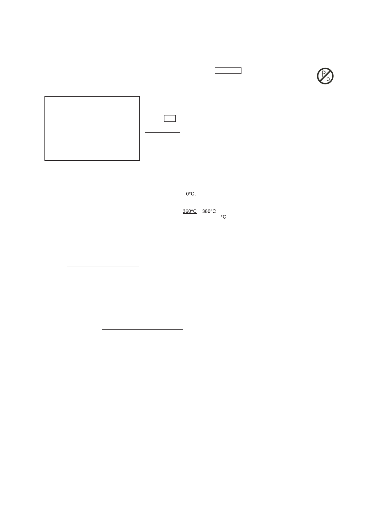
INFORMATION ABOUT LEAD-FREE SOLDERING
Philips CE i
s producing lead-free sets from 1.1.2005 onwards.
IDENTIFICATION:
Regardless of special logo (not always indicated) one must treat all sets from 1 Jan 2005 onwards, according next rules:
Example S/N:
Bottom line of typeplate gives a 14-digit S/N. Digit 5&6 is the y
ear, digit 7&8 is the week number,
so in this case 2005 wk12
So from 0501 onwards = from 1 Jan 2005 onwards
Im por
tant note
:
In fact also products of year 2004 must be treated in this way as long as
you avoid mixing solder-alloys ( leaded/ lead -free). So best to always use SAC3 05 and the
higher temperatures belong to t his.
Due to lead-free
technology some rules have to be respected by the workshop during a repair:
• Use only lead-free solder alloy Philips SAC305 with order code 0622 149 00106. If lead-free solder-paste is required, please contact
the manufacturer of your solder-equipment. In general use of solder-paste within workshops should be avoided because paste is not
easy to store and to handle.
• Use only adequate solder tools applicable for lead-free solder alloy. The solder tool must be able
o To reach at least a solder-temperature of 40
o To stabilize the adjusted temperature at the solder-tip
o To exchange solder-tips for different applications.
•
Adjust your solder tool so that a temperature around
− is reached and stabilized at the solder joint. Heating-time of the
solder-joint should not ex
ceed ~ 4 sec. Avoid temperatures above 400 otherwise wear-out of tips will rise drastically and flux-fluid
will be destroyed. To avoid wear-out of tips switch off un-used equipment, or reduce heat.
• Mix of lead-free solder alloy / parts with leaded solder alloy / parts is possible but PHILIPS recommends strongly to avoid mixed
solder alloy types (leaded and lead-free).
If one cannot avoid or does not know whether product is lead-free, clean carefully the solder-joint from old solder alloy and re-solder
with new solder alloy (SAC305).
• Use only original spare-parts listed in the Service-Manuals. Not listed standard-material (commodities) has to be purchased at
external companies.
• Special information for BGA-ICs:
- alwa
ys use the 12nc-recognizable soldering temperature profile of the specific BGA (for de-soldering always use the lead-free
temperature profile, in case of doubt)
- lead free BGA-ICs will be delivered in so-called 'dry-packaging' (sealed pack including a silica gel pack) to protect the IC against
moisture. After opening, dependent of MSL-level seen on indicator-label in the bag, the BGA-IC possibly still has to be baked dry.
(MSL=Moisture Sensitivity Level). This will be communicated via AYS-website.
Do not re-use BGAs at all.
• For sets produced before 1.1.2005 (except products of 2004), containing leaded solder-alloy and components, all needed spare-parts
will be available till the end of the service-period. For repair of such sets nothing changes.
• On our website www.atyourservice.ce.Philips.com
you find more information to:
∗
BGA-de-/soldering (+ baking instructions)
∗
Heating-profiles of BGAs and other ICs used in Philips-sets
You will find this and more technical information within the "magazine", chapter "workshop news".
For additional questions please contact your local repair-helpdesk.
SERVICE INSTRUCTION
1. Unplug the AC Power cord and connect a wire
between the two pins of the AC Power plug.
2. Set the AC Power switch to the "on" position (keep the
AC Power cord unplugged!).
3. Measure the resistance value between the pins of the
AC Power plug and the metal shielding of the tuner or
the aerial connection on the set. The reading should be
larger than 4.5 Mohm (For U.S. it should be between
4.2 Mohm and 12 Mohm).
4. Switch "off" the set, and remove the wire between the
two pins of the AC Power plug.
Safety regulations require that after a repair, the set must be returned in its original condition. Pay in particular attention to
the following points:
· Route the wire trees correctly and fix them with the
mounted cable clamps.
· Check the insulation of the AC Power lead for external
damage.
· Check the strain relief of the AC Power cord for proper
function.
· Check the electrical DC resistance between the AC Power
Plug and the secondary side (only for sets which have a AC
Power isolated power supply):
• Check the cabinet for defects, to avoid touching of any
inner parts by the customer.
-/93
-/93
2 - 2
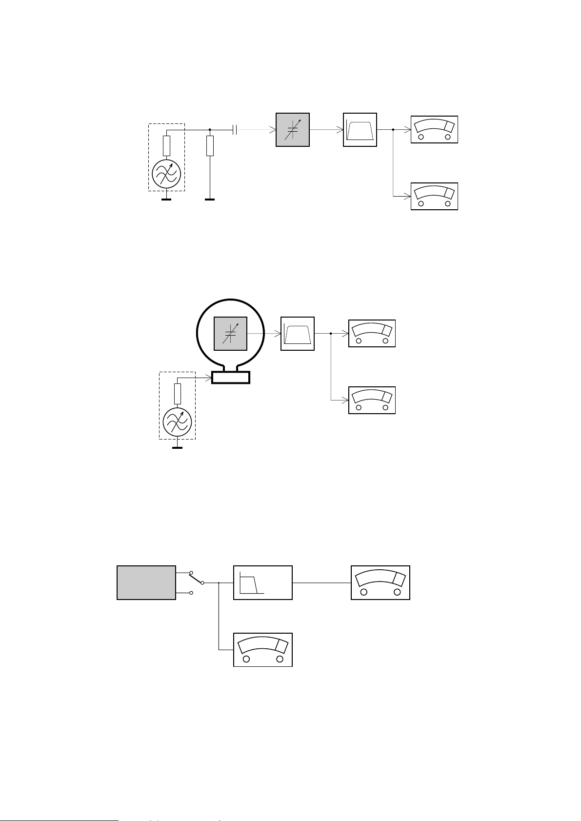
SER
VICE MEASUREMENT
Bandpass
250Hz-15kHz
e.g. 7122 707 48001
LF Voltmeter
e.g. PM2534
DUT
RF Generator
e.g. PM5326
S/N and distortion meter
e.g. Sound Technology ST1700B
Tuner SW
To avoid atmospheric interference all AM-measurements have to be carried out in a Faraday«s cage.
Use a bandpass filter (or at least a high pass filter with 250Hz) to eliminate hum (50Hz, 100Hz).
Ri=50Ω
Aerial replacement
Capacitor
R=50Ω
Bandpass
250Hz-15kHz
e.g. 7122 707 48001
LF Voltmeter
e.g. PM2534
DUT
S/N and distortion meter
e.g. Sound Technology ST1700B
Frame aerial
e.g. 7122 707 89001
Tuner AM (MW,LW)
To avoid atmospheric interference all AM-measurements have to be carried out in a Faraday«s cage.
RF Generator
e.g. PM5326
Ri=50Ω
Low pass filter 22kHz
L
R
LEVEL METER
e.g. Sennheiser UPM550
with FF-filter
S/N and distortion meter
e.g. Sound Technology ST1700B
DUT
CD
Use Audio Signal Disc SBC429 4822 397 30184 (replaces test disc 3)
L.P.F. = 13
th
order filter 4822 395 30204
3 - 1
VIDEO
OUT
AUDIO
OUT
7
@
#
$
%
9
0
!
8
1
2
5
6
4
3
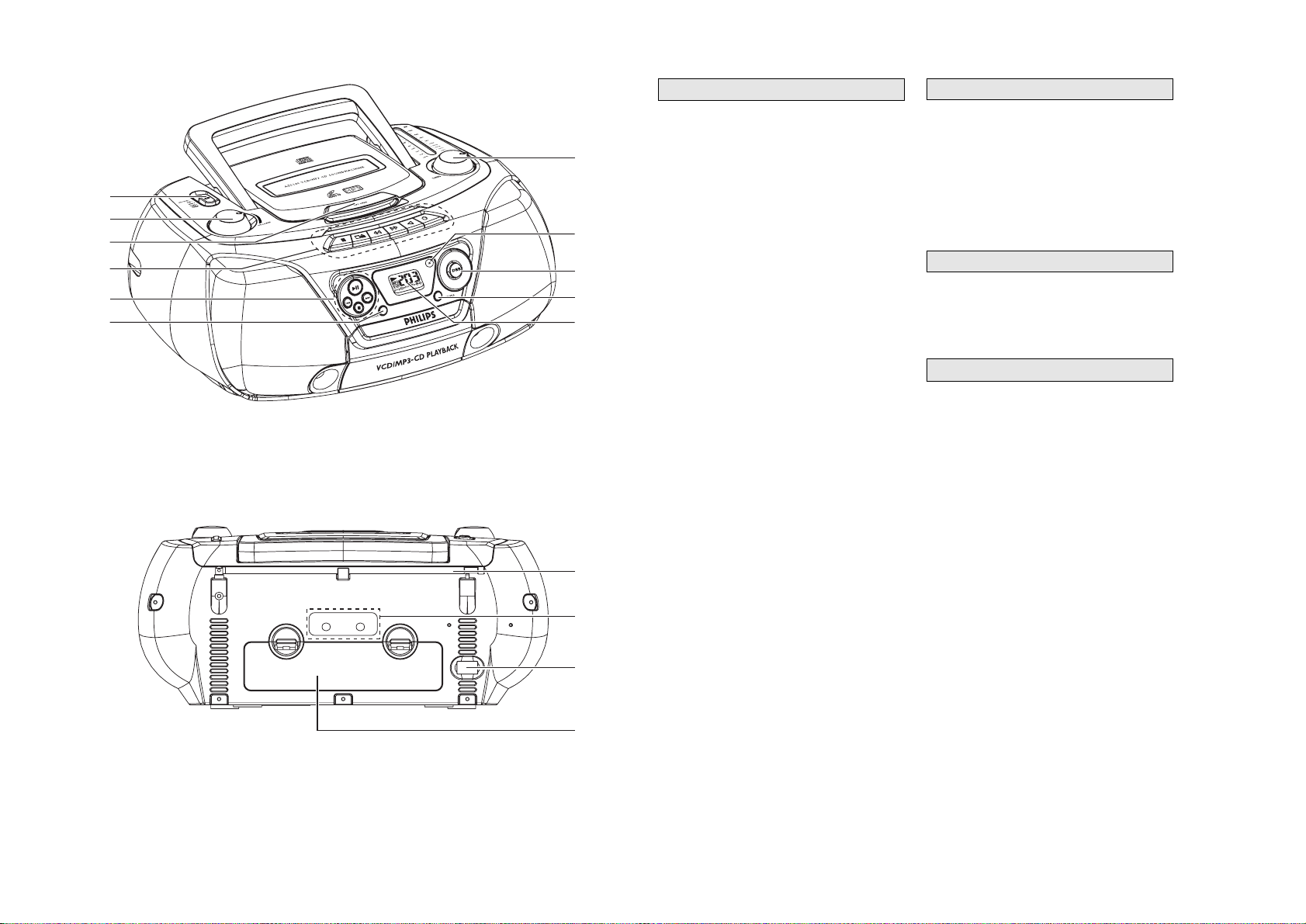
CONTROLS
1 Source selector - power on/off switch and to
select source of sound source:
CD•VCD/MW/FM/T
APE.
2 VOLUME - to adjust volume level.
3 LIFT - OPEN - to open the CD door.
4
Cassette keys:
; - to interrupt recording or playback.
9/- to stop the tape and to open the cassette
holder
.
5 /6 - to fast wind/rewind the tape.
1 - to start playback.
0 - to start recording.
5 2; - to start or interrupt CD playback.
9 - to stop playback
/ §
§
- to skip or search a passage or a track
6 REPEA
T - to repeat a track/programme/entire
CD playback
7 TUNING - to tune to radio stations
8
iR - infrared sensor for remote control
9 DBB
(Dynamic Bass Boost) - for a more
vivid bass response.
0 SHUFFLE - to play all tracks in random order
! LCD Display - to show the VCD, MP3 functions
and disc status.
@
Telescopic aerial - to improve FM radio
reception
#
VIDEO/AUDIO OUT - connect to the TV or
VCR VIDEO/AUDIO IN
$ AC MAINS
~ - socket for mains lead
% Battery door - to open the battery
compartment
Remote Control
. . . . . . . . . . . . . . . . . . . .
1 pc
Mains Cord
. . . . . . . . . . . . . . . . . . . . . . .
1 pc
Audio / V
ideo Cable
. . . . . . . . . . . . . . . .
1 pc
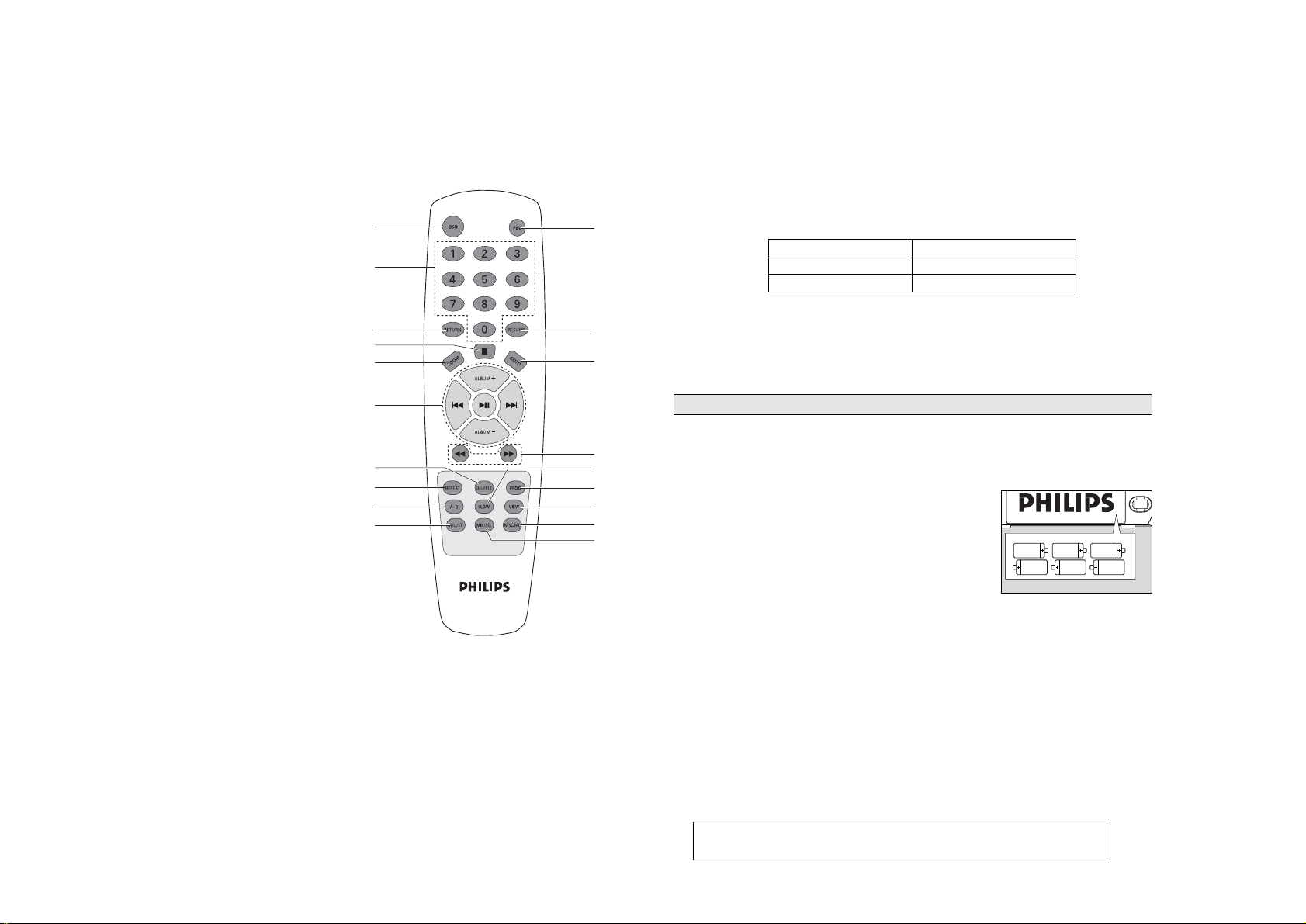
1 OSD - to switch on/off the on screen display on
the TV screen.
2 PBC (PLAYBACK CONTROL) - to switch on or
off PBC mode (for VCD version 2.0 only).
3 DIGITS 0 - 9
for CD/VCD/MP3-CD - to select a
track number.
(numbers consisting more than 2 figures must
be keyed in within 2 seconds)
4 RETURN - to return to the previous MENU level
during playback (for VCD with PBC on).
5 RESUME - to resume playback in stop mode.
6 STOP 9
- to stop playback or to clear a programme.
7 ZOOM
for VCD only
. . . . . . . to zoom in or zoom out
picture.
8 GOTO - to start playback at any chosen time on
the disc (for CD/VCD operation only and PBC
mode is off).
REMOTE CONTROL
SUPPLIED ACCESSORIES
BACK P
ANEL
TOP AND FRONT P
ANEL
CONNECTIONS AND CONTROLS
3 - 2
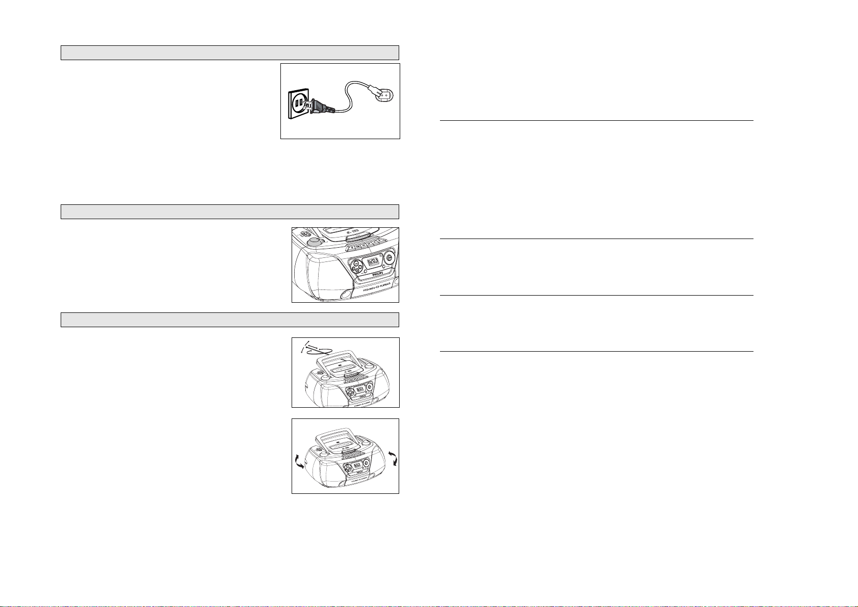
POWER SUPPL
Y
IMPORT
ANT!
•
For best CD/MP3-CD/VCD playback, please plug in your set to an AC power supply
where convenient.
•
If operated in DC mode, see below approximate playtime. (Playtime is also varied from
different brand batteries) :
•
The CD part of this system also serves as a Video
CD player if you connect it to your
TV set.
•
Before viewing the Video
CD, ensure that the set is switched to corresponding PAL or
NTSC system of your TV set (exception Multi-system TV).
Whenever convenient, use the mains supply if you want to conserve battery life. The battery supply
will be switched off when the set is connected to the mains.
Make sure you remove the plug from the
set and wall outlet before inserting batteries.
Batteries
1.
Open the battery compartment and insert six batteries, type
R14, UM2 or C-cells, (preferably alkaline) with the correct
polarity as indicated by the "
+
" and "-" symbols inside the
compartment.
Remote control
1.
Open the battery door and insert two batteries,
type AAA, R03 or UM4 (preferably alkaline).
2.
Replace the compartment door
, making sure the batteries are
firmly and correctly in place.
3.
Remove the batteries if they are exhausted or if they will not be used for a long period.
– The incorrect use of batteries can cause electrolyte leakage and will corrode the compartment
or cause the batteries to burst. Therefore:
– Do not mix battery types, e.g. alkaline with zinc carbonate.
– When inserting new batteries, replace all at the same time.
– Remove the batteries if the set is not to be used for a long time.
Note :
–The battery supply is switched off when the set is connected to the mains.
TV screen is disabled during CD / MP3-CD playing if your AZ5140 is battery
powered.
Batteries contain chemical substances, so they should be disposed of properly.
6 x 1.5V R14/ UM2/ C CELL
BA
TTERIES (NOT SUPPLIED)
Battery type Playtime
Alkaline approximate 9 hrs
Zinc Cartonate approximate 45 minutes
CONNECTIONS AND CONTROLS
REMOTE CONTROL
9 2;
- to start or interrupt playback.
§
§
for
MP3-CD only
. . . . to select previous/next
title.
for CD/VCD . . . . . . . . to search backward/
forward track.
ALB
UM+
/
-
for MP3-CD only
. . . . to select previous / next
album
0 5 / 6 (for CD/VCD/MP3-CD)
- to search back or forward.
! SHUFFLE - When in CD/VCD mode, press to
start or stop shuffle play mode (for VCD, only
available in PBC off mode)
@ REPEAT
for MP3-CD to repeat a track, or
whole disc.
for CD/VCD . . . . . . . .to repeat a disc track or
the whole disc.
# A - B - to playback a certain scene or passage
repeatedly (for CD/VCD operation only).
$ R/L/ST - to select channel left / channel right /
stereo sound, or to select a language in a
bilingual VCD.
% SLOW - to watch a VCD at a slower speed (for
VCD operation only).
^ PROG
for CD/VCD/MP3-CD to programme disc
tracks.
& VIEW - to scan through a VCD with 9 pictures
display on TV screen.
* NTSC/PAL - to select the video output for
NTSC or PAL system.
( MIX/SEL - to select disc format (CD / MP3-CD)
in a mixed mode disc.
1
4
7
9
@
#
$
!
6
3
2
5
8
0
^
&
*
(
%
3 - 3
TROUBLESHOOTING
Problem
Solution
CD/VCD OPERA
TION
"NO DISC" is displayed
–
Insert a disc.
–
Check if the disc is inserted upside down.
–
Wait until
the moisture condensation at the lens has
cleared.
–
Replace or clean the disc, see "Maintenance"
–
Use a readable disc or correct recorded format
MP3-CD.
No picture on TV screen
–
Connect the cable between the system and TV
.
No colour on TV
–
Change the system to the respective P
AL or
NTSC setting.
RADIO RECEPTION
Radio reception is poor
–
If the signal is too weak, adjust the antenna
for better reception.
–
Increase the distance between the Receiver
and your TV or VCR.
TAPE OPERA
TION/RECORDING
Recording or playback cannot be made
–
Clean deck parts, see "Maintenance".
–
Use only NORMAL (IEC I) tape.
–
Apply a piece of adhesive tape over the missing
tab space.
GENERAL
The system does not react when buttons
–
Slide the source sector to T
APE/OFF. Remove and
pressed/set does not work/no display on reconnect the AC power plug for 30 seconds and
LCD. switch on the set again.
Sound cannot be heard or is of poor
–
Adjust the volume.
quality
–
Make sure the MP3-CD was recorded within
32-320 kbps (128kbps preferably) with sampling
frequencies at 8 - 48 kHz (44.1kHz preferably).
The remote control does not function
–
Reduce the distance between the remote control
properly
and the system.
–
Insert the batteries with their polarities (+/- signs)
aligned as indicated.
–
Replace the batteries.
–
Point the remote control in the direction of the
system's IR sensor
.
If a fault occurs, first check the points listed below before taking the set for repair.
If you are unable to remedy a problem by following these hints, consult your dealer or service centre.
WARNING:
Do not open the set as there is a risk of electric shock. Under no
circumstances should you try to repair the set yourself, as this will
invalidate the guarantee.
CONNECTIONS AND CONTROLS
GENERAL
OPERATION
1.
Check if the mains voltage as shown on the type plate (on
the bottom of the set) corresponds to your local mains
voltage. If it does not, consult your dealer or service
organization.
2.
Connect the mains lead to the AC MAINS
~
socket and the
wall socket.
™ The set is now ready for use.
3.
To switch off the mains supply completely
, pull the mains plug out of the wall socket.
™ Disconnect the mains lead when you change over to battery supply, or to protect the set
during heavy thunderstorms.
The type plate is located on the bottom of the set.
1.
To switch on the set, adjust the source selector
.
2.
Adjust the sound using the VOLUME and DBB controls.
3
To switch off the set, adjust the source selector to the
TAPE/OFF position, with the cassette keys released.
1
Set the source selector to FM or MW.
2.
Adjust
the sound using the VOLUME controls and the DBB
switch.
3.
Tune to a radio station using the TUNING knob.
– For FM, pull out the telescopic aerial. T
o improve FM-reception,
incline and turn the aerial. Reduce its length if the FM-signal is
too strong (very close to a transmitter).
– For MW, the set is provided with a built-in aerial, so the
telescopic aerial is not needed. Direct the aerial by turning
the whole set.
4.
To switch off, set the source selector to the T
APE/OFF
position (with the cassette keys released).
RADIO RECEPTION
GENERAL OPERA
TION
MAINS
4 - 14 - 1
A.Remove Back Cabinet
A1 remove screws M3x30 (5pcs)
A2 remove screws
T3x7.5 (1pcs)
D.Remove Motherboard
D remove screws M3x11 (6pcs)
E.Remove T
uner board
E remove screws M3x10 (5pcs)
F
.Remove Tuner Slider Assy and then remove cd cover
F remove screws M3x10 (5pcs)
G remove screws M3x10 (5pcs)
H.Remove CD Motor
H remove screws M3x10 (4pcs)
I.Detach The T
op Cover
I remove screws M3x15 (2pcs)
J.Remove the
Tape & Speaker
J1 remove screws M3x10 (4pcs)
J2 remove screws M3x8 (1pcs)
K remove screws M3x8 (8pcs)
L.Remove the Key Cover
L remove screws M3x8 (4pcs)
M.Remove the Key Board
M remove screws M2.6x7 (5pcs)
B.Remove T
op Cover
A1 remove screws M3x10 (3pcs)
C.Remove The
Handle
(press the two ribs vertical direction, and then slide)
A1
A2
I
J1
J2
D
E
F H
M
L
K
G
DISASSEMBLY DIAGRAM
 Loading...