

Philips AZ3811/55, AZ3811/61, AZ3811/78 Service Manual
Version 1.1
AZ3811
3141 785 36371
MP3/WMA-CD 5W CD Soundmachine
/55/78/61
Published by SW 1121 Service Audio Subject to modification
©
Copyright 2011 Philips Consumer Electronics B.V. Eindhoven, The Netherlands
All rights reserved. No part of this publication may be reproduced, stored in a retrieval
system or transmitted, in any form or by any means, electronic, mechanical, photocopying,
or otherwise without the prior permission of Philips.
CONTENTS
Technical specification and disassemble diagram ...........................1
Service and safety instructions.........................................................2
Block diagram ................................................................................3-1
Wiring diagram ..............................................................................4-1
Main+Radio+Rectifier board
Circuit diagram ..................................................................5-1..5-3
Layout diagram ..................................................................5-4..5-5
Display board
Circuit diagram .........................................................................6-1
Layout diagram .........................................................................6-2
Exploded view diagram .................................................................7-1
Revision list ...................................................................................8-1
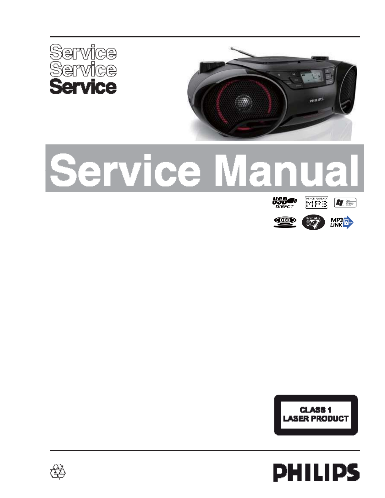
DEPICTION Pos
3
Description Page
1 STOP KEY
2 TUNING KEY -
ALBUM KEY 4 PROG KEY
5
7
9
11
MODE KEY
6 LCD LENS
DSC KEY
10 PLAY KEY
VOLUME KNOB
8 DBB KEY
TUNING KEY +
13 SPEAKER GRILL(L)
14 SOURCE KNOB
12 ALBUM KEY +
15 CASSETTE DOOR
16 USB SOCKET
17 SPEAKER GRILL(R)
Battery location
8 x 1.5V “D-CELL” (UM1)
R20 or equivalent
Dimensions without Boxes (W x H x D):
Weight (including packing):
. xxxKg
CABINET
Dimensions with Boxes (W x H x D):
Material:
Finishing: Spray
Unit in Master carton: N/A
Weight (excluding packing and batteries):
xxxKg
Units in Dealer carton: 1 set
Remark :
FRONT PANEL SPECICFICATION
Class No
AZ3811
Issued Date
1/11/2011
1/11/2011
SH 190 - 1
2011-01-11
A4NAME : Mo Lam Kei 8
SH 190 1
A4
KT CHECK CMT
NAME : Mo Lam Kei
8
USB CD
GENERAL DESCRIPTION
CDSM with Tuner , CD, USB
Aux In, Headphone
LIFETI ME : 5 Years
Class Tuner Supply + A mplifier Loudspeaker Boxes
XX
Recorder
XX
II
I
III
ALL climates : - 10 Dregree till + 50 Degree
RADIATION / IMMUNI TY requirments ( EMC )
CLIMATIC requirem ents
Refer to the section of Version Overview
PERFORMANCE CLASSES
POWER SUPPLY
MAINS ( A.C. ) 120/230Vac ± 15% 230 Vac ± 10 % 120V+/-15% 220V-10%,240+10% 99-146V, 196-264Va c
Refer to the section of Version Overview
SAFET Y requirements
V
ersion
97 / 98
/12
/96
Voltage Selection Yes No No
Frequency 60 / 50Hz 50 Hz 60 Hz
ECO Power mode : N/A
@ 1/8 Prated , NOM. A, INPUT
Class No
GENERAL PART 1 - GENE RAL SPECICFICATION
1/11/2011
AZ3811
Issued Date
A4
1/11/2011
2011-01-11
CMT
NAME : Mo Lam Kei
KT CHECK
8 SH 190 - 4
Remarks :
14W
DC operation / Backup Buffer
R20 (UM1 / D-cell) x 6 (9V norm al, 6.3V limit)
55 / 77 / 78
Yes
60 / 50Hz
/73
No
50 Hz
Battery type :
Maximum :
( DEMO mode " OFF " ) , NOM. A, INPUT
Standby :
DC operation / Backup Buffer
POWER CONSUMER
MAINS ( A.C. )
N.A
TECHNIAL DESCRIPTION
2 x 2W matching LOUDSPEAKER of 2 x 8R. One INPUT SOURCE
GENERAL PART
N.A
N.A
N.A
Standby Mo de Indicator : LCD display off
ECO Mode Indiicator : NA
ELECTRICAL DATA
DBB Yes Hum ( Volume Minimun )
DSC : NA
OUTPUT stage Protection : Yes Temperature : YES Shorcircuit : Yes
.
INDICATORS
SIS : N/A Residual Noise ( Volume Minium ) 0.06
0.5
uW
WOOX : N/A
uW
VAC : N/A
Headphone
AUX 500mV Digital Coaxi al Out
Subwoofer Out
INTERCONNECTS
Input Sensitity (
±
dB ) rated ouput power at 1 kHz
Line Output Voltage ( * 1 )
-6 dB track (Audio Disc 1 ,Trk 35 Booster Out
USB
Tuner FM 67.5KHZ,AM80% Modulation(L imit :-6db) Line Out ( Left / Right )
CD -6 dB track (Audio Disc 1 ,Trk 35
-6 dB track (Copy from Audio Disc 1 ,Trk 35)
15 mW - 2 dB ,
at R Load = 32 ohm @ max volume, 0dB, 1kHz CD
Microphone
3
: 2.5W, 1 Channels (Lim: -1dB)
( At Cold Condition with 10% THD )
OUTPUT POWER ( * 1 ) At THD = 10% , 1KHz sinewave
Main Operation
( At 500mW Output in flat Mode)
LOUDSPEAKER ( BOXES )
DC Operation : .2.5W, 1 Channels (Lim: -1dB)
Frequency Response : 125Hz - 14KHz
with rated input signa l in AUX mode; wi t h DBB OFF
Rated Impedance
Left / Rig ht : 8 Ohms at 125Hz to 16KHz
GENERAL PART 1 - TECHN AICAL SPECICFICA TION
Remarks
( *1 ) Electrical parameters are to be measuremend at specker terminals across 8 Ohm load ( pure resistor )
A4
1/11/2011
1/11/2011
Issued Date
CMT
NAME : Mo Lam Kei
KT CHECK
8 SH 190 - 5
2011-01-11
AZ3811
Class No
Remarks Time Setting : NA
Timer Wakeup Mode : NA
TECHNIAL DESCRIPTION
CLOCK PART
Timer Setting : NA
INDICATORS
No of Timer Settings
CD PART
Display Type : LCD
: NA
Clock Accuracy : NA
Volume at Wakeup : NA
THD (1kHz) : 1.5%(Lim 2.0%)
Channel Unbalance (250 t o 10k Hz) : <= 3dB
Frequency Response(±3dB)
(@ volume max - 20dB and DBB off mode)
: 100Hz~10k Hz
Signal to Noi s e Ratio(A-weighted) : 62dBA(L im 57 dBA)
Channel Separation(10K) : 30dB (Lim. 16dB)
CD Shock sens. : 5kg
THD (100 ~10kHz) : 2%(Lim 3.0%)
Channel Separation(1K) : 40dB (Lim. 26dB)
DBB 8+/- 2 dB at AUX 500mV, 1kHz
DBB effect
USB PART
- Refer to Philips USB direct user requirement
spec.
CLOCK / CD SPECICFICATIO N
Issued Date
1/11/2011
Class No
AZ3811
2011-01-11
1/11/2011
A4SH 190 - 6
CMT
NAME : Mo Lam Kei
KT CHECK
8
文档
40 dB 40 dB
Modulation Hum
45
Search Tuning Stop Accuracy RF:
FM Channel Seprantion -400/1K/5K
21/25/18 18/20/15 dB
50 dBA
Search tuning stop accuracy
TECHNIAL DESCRIPTION
GENERAL PART
FM S/N Ratio(A weighted) Mono input
80dBf
55
WAVE RANGE
FM
Refer to version overvie
w
AM
MW
Refer to version overvie
w
Refer to version overvie
w
Limit Unit
AERIAL
FM : Telescope
AM/MW : Ferrite
INDICATORS : NA
± 0.3 MHz
ELECTRICAL DATA
A.M Nom Limit Unit F.M. Nom
IF
450 ± 3 kHz
IF
: 10.7
5%
AGC figure of merit
30 25 dB
- 3 dB Limiting Point
: 17 25 dBf
Stereo - 46 dB Quieting
48 51 dBf
Distortion ( RF 50mV , m=80% )
35%
Distortion ( RF 1mV , Frq Dev.75 kHz )
3
Modulation Hum
45
Search tuning sensitivity
dBuV/m48 - 72
Search tuning sensitivity
24-32 19 - 35 dBf
+/- 10Step
91~120dB
f
R/F:31~91dBf
RF >= 1V/
m
RF >= a26 to 1V/m
+/- 1
0
Wave Range Noise Limited Sensitivity 26 dB
Image Rejection
IF Rejection
Lim.
-- 22 50
dBf
24
55
dBf
-- 18
120 dBuV/m
AM / MW
Nom.
-- 64
FM
Nom.
32
28
20
Lim.
-- 72 dBuV/m
28
24 114 dBuV/m
dBuV/m
dB
dB
Remarks
TUNER SPECICFICATION
Class No
AZ3811
Issued Date
CMT
NAME : Mo Lam Kei 8
1/11/2011
1/11/2011
A4
KT CHECK
SH 190 - 7
2011-01-11
Search Time
60 Sec.
Search Time
60 Sec.
130dBf
125dBf
Large Signal
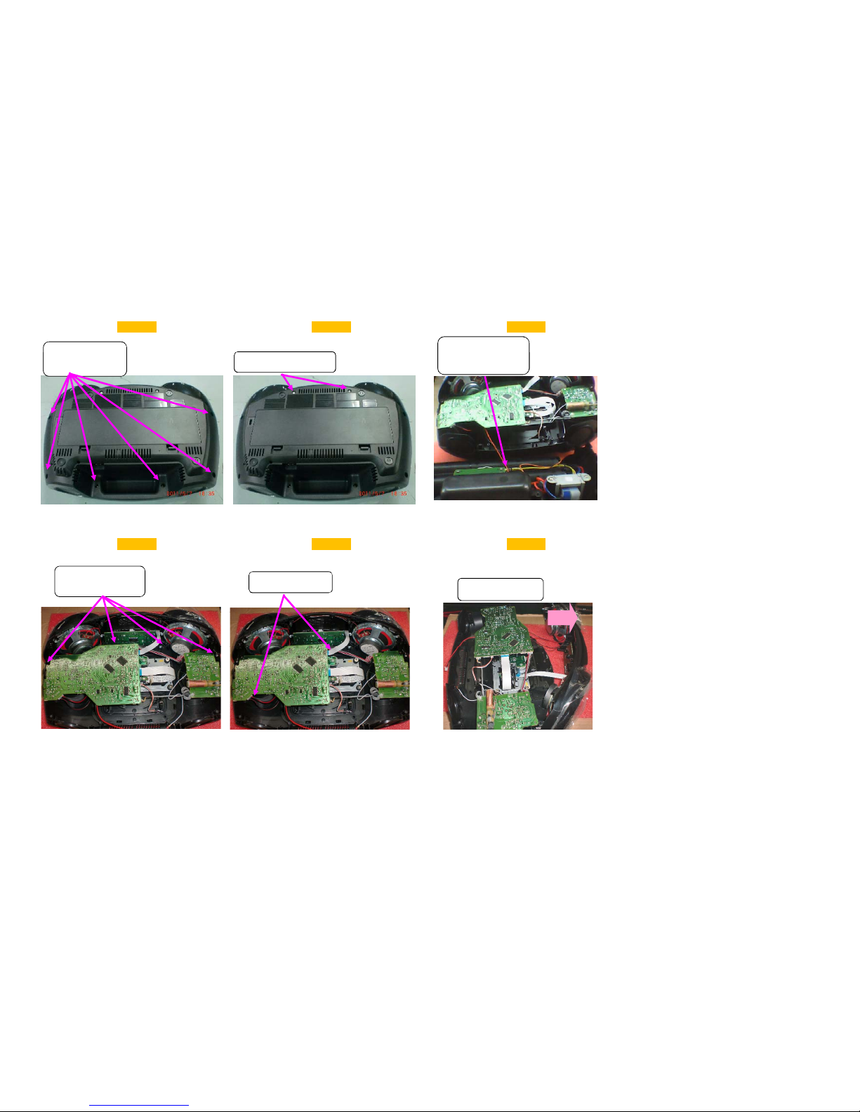
1a 1b 1c
1 、 Disassemble botttom cabinet
disassemble six 3 x 12 PB
screws from the top
cabinet
disassemble two 3 x 8 PB screws
on bottom cabinet
remove the bottom cabinet
and unplug the 2pin cable
between Main BD and power
BD
screws from the top
cabinet
disassemble two 3 x 8 PB screws
on bottom cabinet
and unplug the 2pin cable
between Main BD and power
BD
2、 Disassemble front cabinet
2a2b
2
c
disassemble the four 3 x 8
PB screws which connect top
unplug 4pin speaker cable
sperate top cabinet and
PB
screws which connect top
cabinet and front cabinet
unplug 4pin speaker cable
and 10pin FFC cable
sperate top cabinet and
front cabinet
p
p
ull
3-a 3-b 3-c
3A、 Disassemble Main BD
disassemble the five 2.6 x 8
PB screws on Main BD
unplug the 4pin cable,2pin open-close
cable,4pin cable to radio BD and 6pin cable
to CD Deck on Main BD
remove
volumn
knob and
get out
Main BD
3-d 3-e
3-f
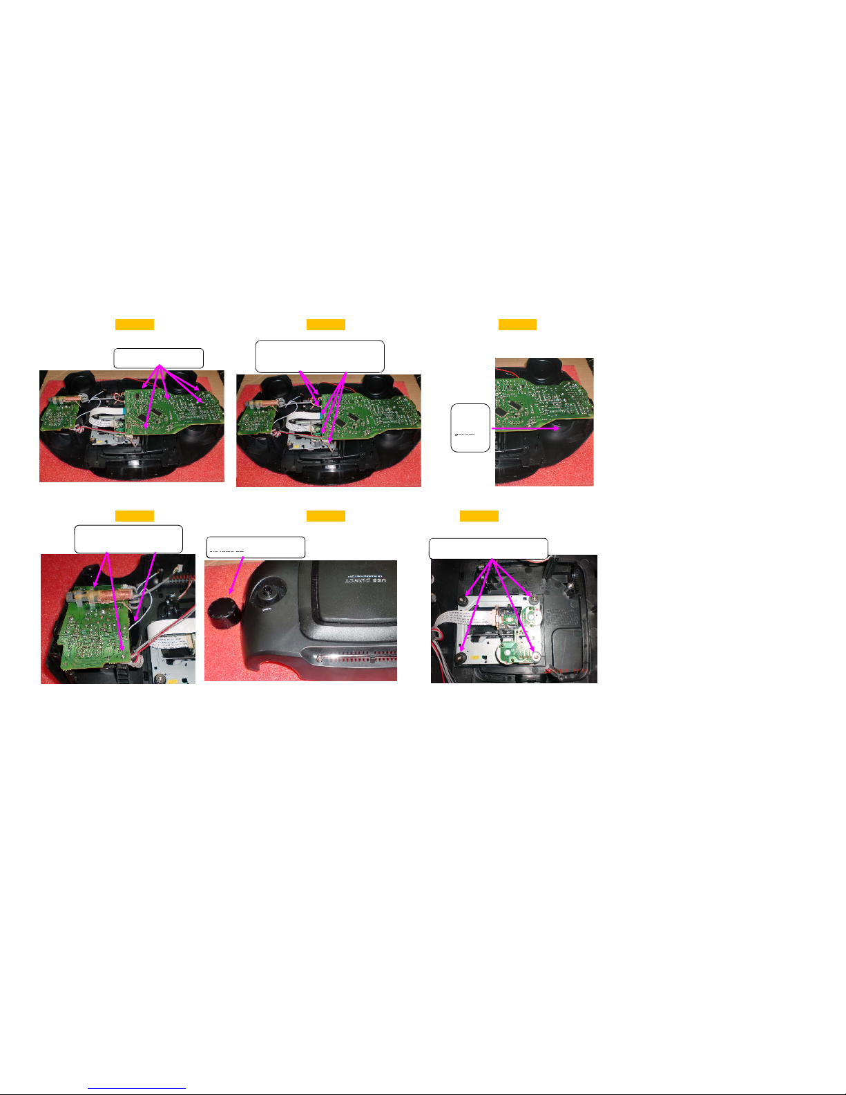
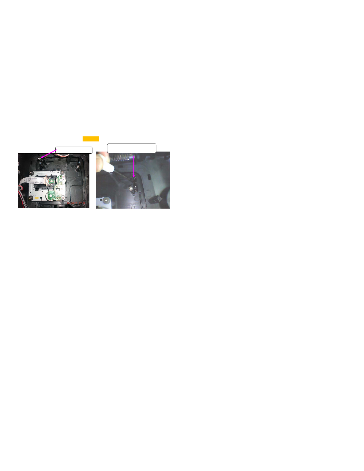
3B、
Disassemble radio BD and CD deck
disassemble the two 2.6 x 8 PB
screws on radio BD,un
plug
FM ANT
disassemble the four 2.6 x 8 PWA
screws on CD deck and get out CD deck
disassemble the two 2.6 x 8 PB
screws on radio BD,unplug FM ANT
cable
unplug tunning knob and get out
the radio BD
screws on CD deck and get out CD deck
the radio BD
3-g
3C、 Disassemble CD door
take out CD door spring first
pull out CD door when goring the CD
door buckle with a screwdriver
 Loading...