

Philips AZ-3013, AZ-3014 Service manual
CD Sound Machine
AZ 3013/00/05
AZ 3014/05
TABLE OF CONTENTS
Handling Chip Components and Safety ..........................1 - 1
Technical Specification & Measurement Setup ...............2 - 1
Service tools ....................................................................2 - 1
Service Measurement......................................................2 - 2
Connections and controls ................................................3 - 1
Block Diagram .................................................................4 - 1
Wiring Diagram................................................................4 - 2
Front Board
circuit diagram .........................................................5 - 1
layout diagram.........................................................5 - 2
Tuner Board
circuit diagram .........................................................6 - 1
layout diagram.........................................................6 - 2
Tuner adjustment ....................................................6 - 2
CD Board
circuit diagram .........................................................7 - 1
layout diagram.........................................................7 - 2
Audio Board
circuit diagram .........................................................8 - 1
layout diagram.........................................................8 - 2
Exploded view .................................................................9 - 1
Mechanical partslist .........................................................9 - 2
Electrical partslist...........................................................10 - 1
©
Copyright 2001 Philips Consumer Electronics B.V. Eindhoven, The Netherlands
All rights reserved. No part of this publication may be reproduced, stored in a retrieval
system or transmitted, in any form or by any means, electronic, mechanical, photocopying,
or otherwise without the prior permission of Philips.
Published by YT 0309 Service Audio Printed in The Netherlands Subject to modification
CLASS 1
LASER PRODUCT
© 3140 785 32410
HANDLING CHIP COMPONENTS
1 - 1
TECHNICAL SPECIFICATIONS
2 - 1
GENERAL
Mains voltage -/00C : 230 V
-/05 : 240V
Mains frequency -/00C/05 : 50 Hz
Battery main set : 9 V (R14 x 6)
Power consumption : < 20 W (max.)
Dimension (W x H x D) : 294 x 145 x 245 mm
Weight : 2.4 Kg
AMPLIFIER
Output power mains : 2 x 1 W
battery : 2 x 1 W
Speaker impedance : 2 x 8 ohm
Frequency response : 100 Hz - 10 kHz (±3dB)
COMPACT DISC
Frequency response : 100 Hz - 10 kHz ± 2dB
S/N ratio : 60 dB
Channel difference 1 kHz : 2 dB
Channel crosstalk 1 kHz : 40 dB
Laser wavelength : 780 ± 20 nm
Laser light power : < 0.5 mW
TUNER - FM SECTION
Tuning range : 87.5 - 108 MHz
IF frequency : 10.7 MHz ± 0.2 MHz
Sensitivity : 20 dBf at 26dB S/N
Selectivity : 30 dB at 300kHz
IF rejection : 50 dB
Image rejection : 20 dB
Crosstalk : 20 dB
TUNER - AM SECTION
Tuning range MW : 531 - 1602 kHz
IF frequency : 450 kHz ± 1 kHz
Sensitivity MW : 4500 µV/m at 26dB S/N
Selectivity MW : 16 dB
IF rejection MW : 60 dB
Image rejection MW : 28 dB
SERVICE MEASUREMENT
2 - 2
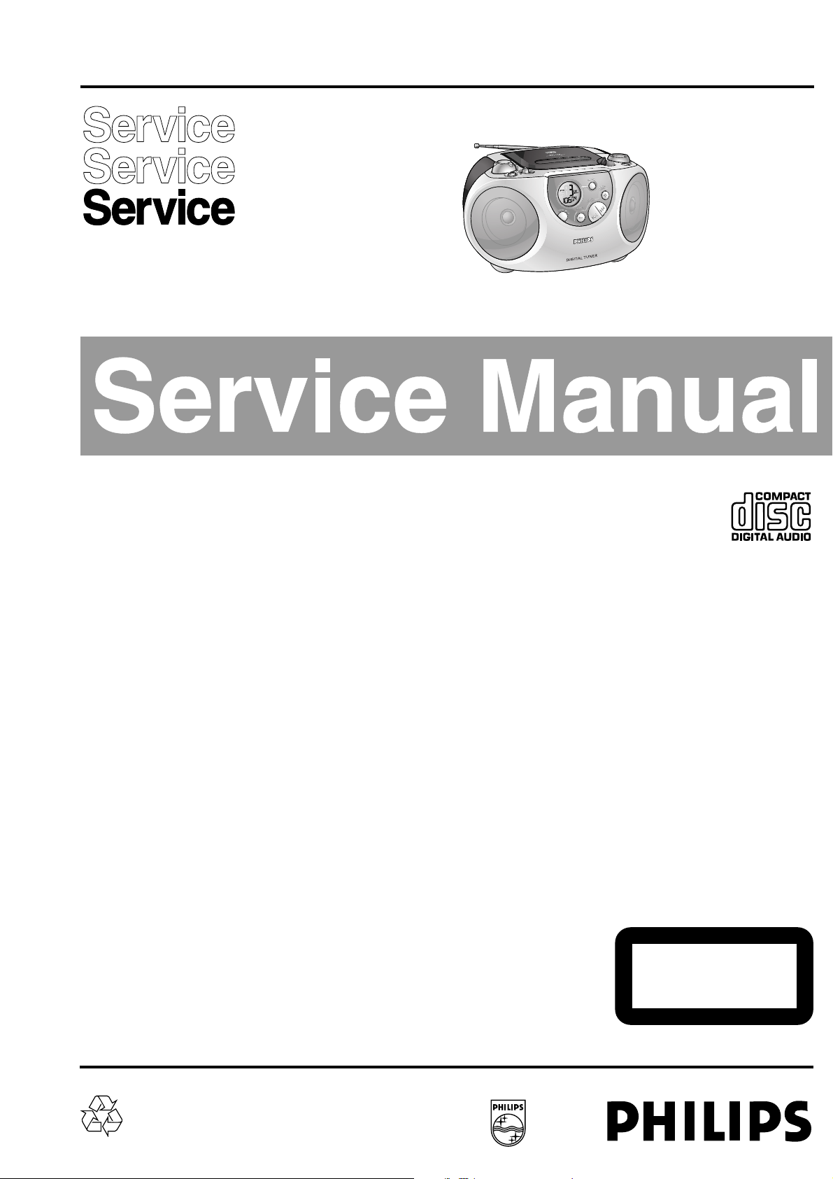
Tuner SW
RF Generator
e.g. PM5326
Aerial replacement
DUT
Capacitor
Ri=50Ω
R=50Ω
Bandpass
250Hz-15kHz
e.g. 7122 707 48001
LF Voltmeter
e.g. PM2534
S/N and distortion meter
e.g. Sound Technology ST1700B
To avoid atmospheric interference all AM-measurements have to be carried out in a Faraday«s cage.
Use a bandpass filter (or at least a high pass filter with 250Hz) to eliminate hum (50Hz, 100Hz).
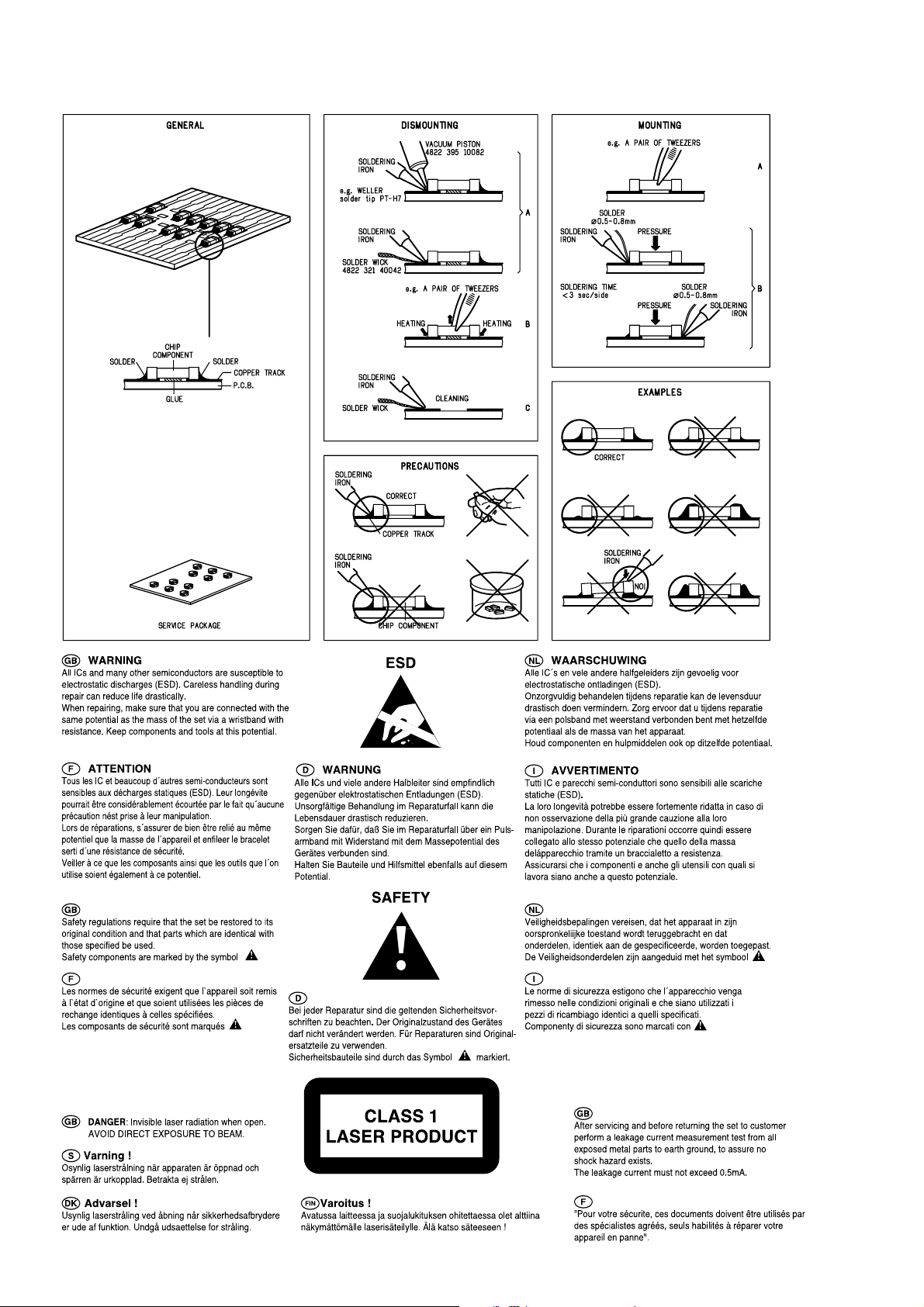
Tuner AM (MW,LW)
RF Generator
e.g. PM5326
Ri=50Ω
DUT
Frame aerial
e.g. 7122 707 89001
Bandpass
250Hz-15kHz
e.g. 7122 707 48001
LF Voltmeter
e.g. PM2534
S/N and distortion meter
e.g. Sound Technology ST1700B
To avoid atmospheric interference all AM-measurements have to be carried out in a Faraday«s cage.
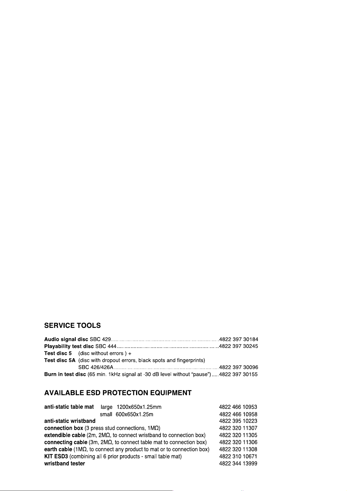
CD
Use Audio Signal Disc SBC429 4822 397 30184 (replaces test disc 3)
L.P.F. = 13
th
order filter 4822 395 30204
DUT
L
R
Low pass filter 22kHz
LEVEL METER
e.g. Sennheiser UPM550
with FF-filter
S/N and distortion meter
e.g. Sound Technology ST1700B
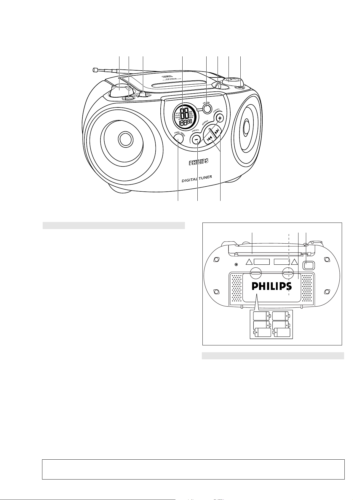
CONNECTIONS AND CONTROLS
1 2 3 4 5 6 7 8
3 - 1
Top and front panels (See 1)
1VOLUME
– adjusts volume level
2DBB (Dynamic Bass Boost)
– enhances bass response
3Source selector
– selects source of sound CD or TUNER. Also the power off switch
4Display
– shows the CD and tuner functions
5FM•MW (AM)
– selects FM/ MW (AM) waveband
6LIFT TO OPEN
– opens/ closes the CD door
7PRESS TO PLAY 2;
– starts or pauses CD play
8STOP 9
– stops CD playback; erases a CD programme
9SEARCH ∞ , §
CD: skips or searches a passage/track backwards or forward
Tuner: tunes to a station (up, down)
0PRESET +, –
– selects a preset station (up, down)
!PROG MODE
CD: – programmes and reviews programmed track numbers;
– plays tracks CD/ programme in random order;
– repeats a track/CD/ programme
Tuner: – programmes preset stations
! 0 9
@ $# %
3 x 2 R14 • UM2 • C-CELLS
Back Panel (See 1)
@Telescopic aerial
– to improve FM reception
#Voltage selector (inside battery compartment,
some versions only)
– adjust to match the local voltage 110/220V before plugging in the set
$Battery door
– to open battery compartment
%AC MAINS
– inlet for mains lead
For more detail on operation instruction please visit Philips Audio internet site :
http://www.audio.philips.com
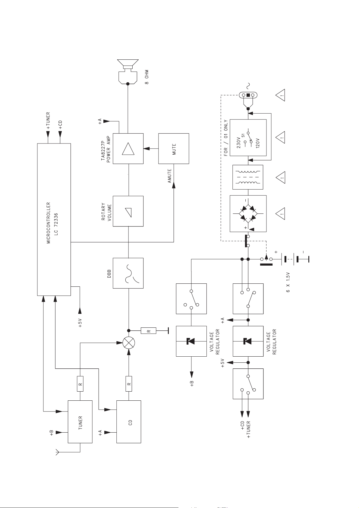
4 - 1
AZ301x /ALL BLOCK DIAGRAM
 Loading...