

Page 1
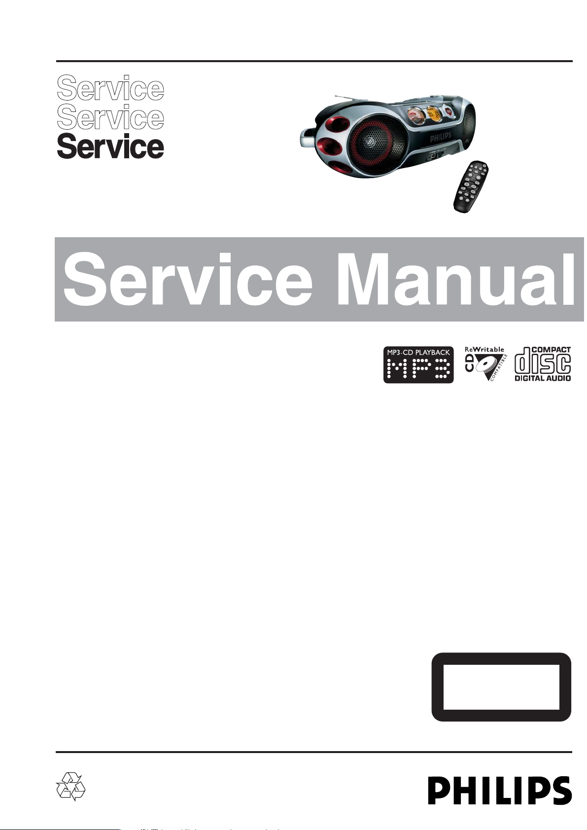
MP3 CD Sound Machine
AZ2537,AZ2538
Handling Chip Components and Safety ..........................1 - 1
Technical Specification & Service tools...........................2 - 1
Service Measurement......................................................2 - 2
Connections and controls.......................................3 - 1..3 - 2
Instruction for use...................................................3 - 3..3 - 4
Disassembly Diagram......................................................4 - 1
Block Diagram .................................................................5 - 1
Wiring Diagram................................................................5 - 2
MCU Board
Circuit diagram...............................................6 - 1..6 - 2
Layout diagram........................................................6 - 3
CD Board
Circuit diagram........................................................7 - 1
Layout diagram ..............................................7 - 2..7 - 3
Tuner Board
Circuit diagram .......................................................8 - 1
Layout diagram .......................................................8 - 2
Tuner adjustment table ...........................................8 - 2
MP3 Board
Circuit diagram........................................................9 - 1
Layout diagram........................................................9 - 2
USB Board
Circuit diagram......................................................10 - 1
Layout diagram........................................................9 - 2
(Only for AZ2538 all versions)
MAIN Board
Circuit diagram......................................................11 - 1
Layout diagram ..........................................11 - 2..11 - 3
Exploded view diagram .................................................12 - 1
Mechanical partslist ......................................................12 - 2
Electrical partslist...........................................................12 - 2
(Circuit and Layout diagram for referrence only)
© 3141 785 30030
Published by LX 0427 Service Audio Printed in The Netherlands Subject to modification
TABLE OF CONTENTS
©
Copyright 2004 Philips Consumer Electronics B.V. Eindhoven, The Netherlands
All rights reserved. No part of this publication may be reproduced, stored in a retrieval
system or transmitted, in any form or by any means, electronic, mechanical, photocopying,
or otherwise without the prior permission of Philips.
version1.0
all versions
CLASS 1
LASER PRODUCT
Page 2
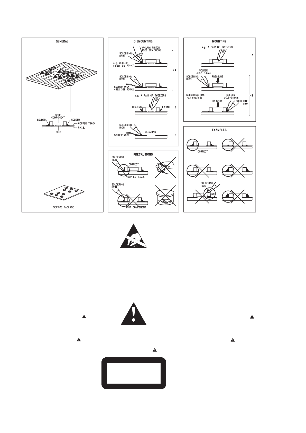
HANDLING CHIP COMPONENTS
1 - 1
© WARNING
All ICs and many other semiconductors are susceptible to
electrostatic discharges (ESD). Careless handling during
repair can reduce life drastically.
When repairing, make sure that you are connected with the
same potential as the mass of the set via a wristband with
resistance. Keep components and tools at this potential.
f ATTENTION
Tous les IC et beaucoup d´autres semi-conducteurs sont
sensibles aux décharges statiques (ESD). Leur longévite
pourrait être considérablement écourtée par le fait qu´aucune
précaution nést prise à leur manipulation.
Lors de réparations, s´assurer de bien être relié au même
potentiel que la masse de l´appareil et enfileer le bracelet
serti d´une résistance de sécurité.
Veiller à ce que les composants ainsi que les outils que l´on
utilise soient également à ce potentiel.
©
Safety regulations require that the set be restored to its
original condition and that parts which are identical with
those specified be used.
Safety components are marked by the symbol
f
Les normes de sécurité exigent que l`appareil soit remis
à l`état d`origine et que soient utilisées les pièces de
rechange identiques à celles spécifiées.
Les composants de sécurité sont marqués
d WARNUNG
Alle ICs und viele andere Halbleiter sind empfindlich
gegenüber elektrostatischen Entladungen (ESD).
Unsorgfältige Behandlung im Reparaturfall kann die
Lebensdauer drastisch reduzieren.
Sorgen Sie dafür, daß Sie im Reparaturfall über ein Pulsarmband mit Widerstand mit dem Massepotential des
Gerätes verbunden sind.
Halten Sie Bauteile und Hilfsmittel ebenfalls auf diesem
Potential.
d
Bei jeder Reparatur sind die geltenden Sicherheitsvorschriften zu beachten. Der Originalzustand des Gerätes
darf nicht verändert werden. Für Reparaturen sind Originalersatzteile zu verwenden.
Sicherheitsbauteile sind durch das Symbol markiert.
ESD
SAFETY
ñ WAARSCHUWING
Alle IC´s en vele andere halfgeleiders zijn gevoelig voor
electrostatische ontladingen (ESD).
Onzorgvuldig behandelen tijdens reparatie kan de levensduur
drastisch doen vermindern. Zorg ervoor dat u tijdens reparatie
via een polsband met weerstand verbonden bent met hetzelfde
potentiaal als de massa van het apparaat.
Houd componenten en hulpmiddelen ook op ditzelfde potentiaal.
i AVVERTIMENTO
Tutti IC e parecchi semi-conduttori sono sensibili alle scariche
statiche (ESD).
La loro longevità potrebbe essere fortemente ridatta in caso di
non osservazione della più grande cauzione alla loro
manipolazione. Durante le riparationi occorre quindi essere
collegato allo stesso potenziale che quello della massa
delápparecchio tramite un braccialetto a resistenza.
Assicurarsi che i componenti e anche gli utensili con quali si
lavora siano anche a questo potenziale.
ñ
Veiligheidsbepalingen vereisen, dat het apparaat in zijn
oorspronkeliijke toestand wordt teruggebracht en dat
onderdelen, identiek aan de gespecificeerde, worden toegepast.
De Veiligheidsonderdelen zijn aangeduid met het symbool
i
Le norme di sicurezza estigono che l´apparecchio venga
rimesso nelle condizioni originali e che siano utilizzati i
pezzi di ricambiago identici a quelli specificati.
Componenty di sicurezza sono marcati con
©
DANGER: Invisible laser radiation when open.
AVOID DIRECT EXPOSURE TO BEAM.
s Varning !
Osynlig laserstrålning när apparaten är öppnad och
spärren är urkopplad. Betrakta ej strålen.
∂ Advarsel !
Usynlig laserstråling ved åbning når sikkerhedsafbrydere
er ude af funktion. Undgå udsaettelse for stråling.
CLASS 1
LASER PRODUCT
ß Varoitus !
Avatussa laitteessa ja suojalukituksen ohitettaessa olet alttiina
näkymättömälle laserisäteilylle. Älä katso säteeseen !
©
After servicing and before returning the set to customer
perform a leakage current measurement test from all
exposed metal parts to earth ground, to assure no
shock hazard exists.
The leakage current must not exceed 0.5mA.
f
"Pour votre sécurite, ces documents doivent être utilisés par
des spécialistes agréés, seuls habilités à réparer votre
appareil en panne".
Page 3

GENERAL
Mains voltage :
-/00C -/00C/01/05
-/17
-/00C/05
230 V
:
-/01 230V/120 V
:
-/05 240V
:
-/17 120 V
Mains frequency :
: 50 Hz
:
-/01 : 50 Hz/60Hz
:
-/17 : 60Hz
Battery mains : 12 V (R20 x 8)
Power consumption :
Dimension (W x H x D) : 480 x
260 x 170 mm
Output power mains : 2 x 4 W
battery : 2 x 4 W
TUNER - FM SECTION
Tuning range : 87.5 - 108 MHz
IF frequency : 10.7 MHz
26dB quieting sensitivity : < 14dBuV
Selectivity S300 : > 15 dB
±0.2MHz
S/N Ratio(A-Wtd) : > 45dBA
IF rejection : > 50 dB
Image rejection : > 20 dB
Output power at 10%THD : > 4000 mW
AM suppression : > 22 dB
TUNER - MW SECTION
Tuning range : 531 - 1602 kHz
: 530 - 1710 kHz
IF frequency : 450 kHz ± 3 kHz
26dB quieting sensitivity : < 74 dB/m
Selectivity : 16 dB
:
IF rejection ratio 24 dB
:
Image rejection 28 dB
< 24 W
Frequency response :
>
>
:
Output power at 10%THD 3800mW
:
Frequency responce -6dB
<100Hz
>
>
COMPACT DISC
:
S/N ratio > 50 dB
:
< 2 mV
+0dB ±3dB at 125Hz
Channel difference : < 3 dB
:
THD (1KHz,0dB) <1.5%
:
Frequency accuracy +/-0.5%
Crosstalk
1 kHz : > 26 dB
Crosstalk
10 kHz : > 16 dB
at S9/300kHz
(1kHz ref.)
Residual hum & noise
:
< 2 mV
:
< 500 mA
Current consumption
:
>4000mW
Rated power 10%THD/1KHz
-Rated output
2 - 1
SERVICE TOOLS
Audio signal disc SBC 429.......................................................................4822 397 30184
Playability test disc SBC 444
...................................................................4822 397 30245
Test disc 5 (disc without errors ) +
Test disc 5A (disc with dropout errors, black spots and fingerprints)
SBC 426/426A.....................................................................4822 397 30096
Burn in test disc (65 min. 1kHz signal at -30 dB level without “pause”)
.....4822 397 30155
anti-static table mat
large 1200x650x1.25mm 4822 466 10953
small 600x650x1.25m 4822 466 10958
anti-static wristband
4822 395 10223
connection box (3 press stud connections, 1MΩ) 4822 320 11307
extendible cable (2m, 2MΩ, to connect wristband to connection box) 4822 320 11305
connecting cable (3m, 2MΩ, to connect table mat to connection box) 4822 320 11306
earth cable (1MΩ, to connect any product to mat or to connection box) 4822 320 11308
KIT ESD3 (combining all 6 prior products - small table mat) 4822 310 10671
wristband tester 4822 344 13999
AVAILABLE ESD PROTECTION EQUIPMENT
TECHNICAL SPECIFICATIONS
Page 4
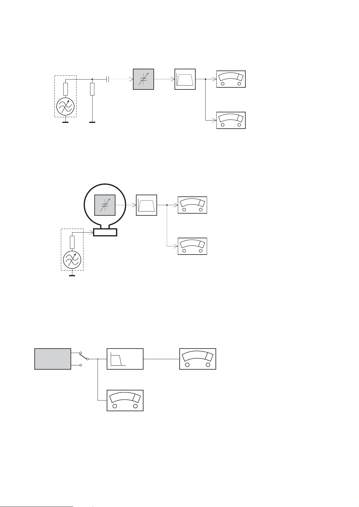
2 - 2
SERVICE MEASUREMENT
Tuner SW
RF Generator
e.g. PM5326
Aerial replacement
DUT
Capacitor
Ri=50Ω
R=50Ω
Bandpass
250Hz-15kHz
e.g. 7122 707 48001
LF Voltmeter
e.g. PM2534
S/N and distortion meter
e.g. Sound Technology ST1700B
To avoid atmospheric interference all AM-measurements have to be carried out in a Faraday´s cage.
Use a bandpass filter (or at least a high pass filter with 250Hz) to eliminate hum (50Hz, 100Hz).
Tuner AM (MW,LW)
RF Generator
e.g. PM5326
Ri=50Ω
DUT
Frame aerial
e.g. 7122 707 89001
Bandpass
250Hz-15kHz
e.g. 7122 707 48001
LF Voltmeter
e.g. PM2534
S/N and distortion meter
e.g. Sound Technology ST1700B
To avoid atmospheric interference all AM-measurements have to be carried out in a Faraday´s cage.
CD
Use Audio Signal Disc SBC429 4822 397 30184 (replaces test disc 3)
L.P.F. = 13
th
order filter 4822 395 30204
DUT
L
R
Low pass filter 22kHz
LEVEL METER
e.g. Sennheiser UPM550
with FF-filter
S/N and distortion meter
e.g. Sound Technology ST1700B
Page 5
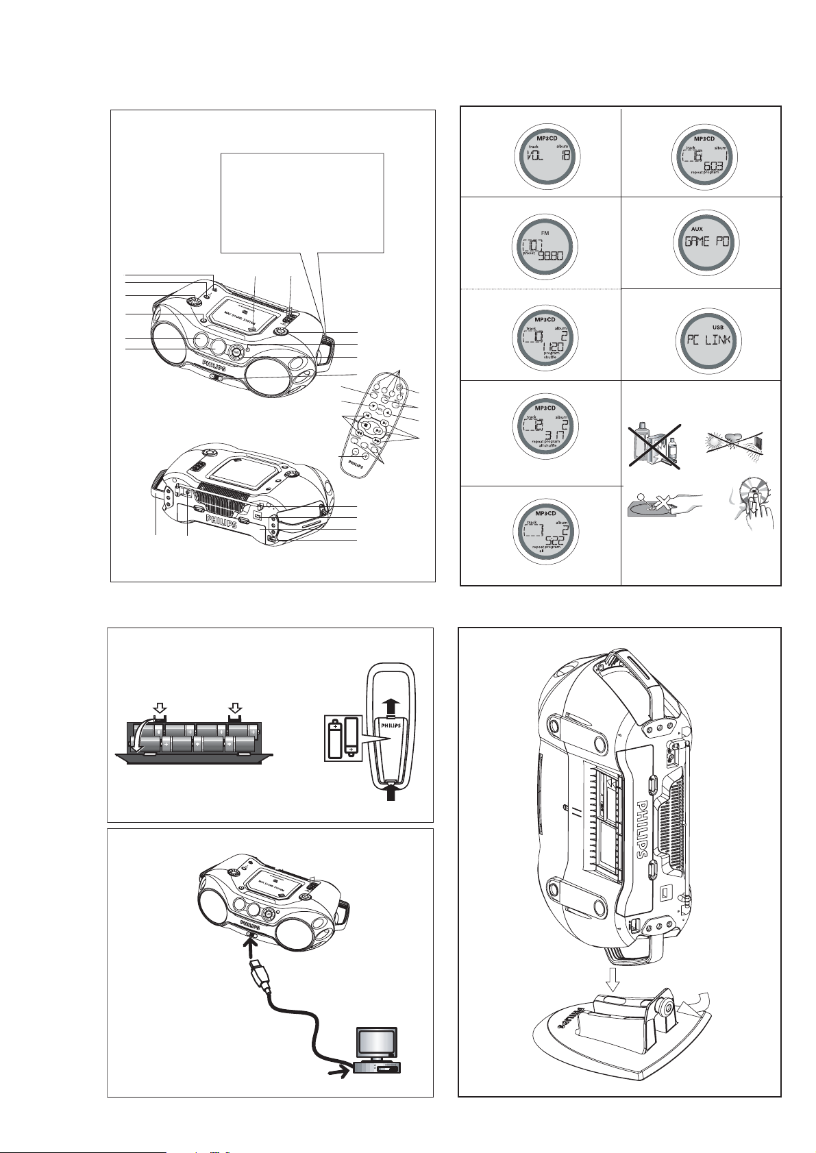
3 - 1
CONNECTIONS AND CONTROLS
1
2
HEAVY !
Take care of your CD Soundmachine.
Grip both handles when you carry or
lift the set.
LOURD !
Soin de prise de votre Soundmachine CD.
Saisissez les deux poign
portez ou déplacez l'appareil.
6
5
4
3
2
1
&
*
7
8
ées quand vous
9
0
!
@
3
4
5
M
ALBUM/
P
R
7
#
$
%
^
1
T
uner
US
B
2
3
4
AX
E
SET
5
6
3
4
5
6
7
8
9
0
X
A
C
8 x D-cells - R20 - UM1
B
USB
D
2 x AAA
1
2
Page 6

3 - 2
SUPPLIED ACCESSORIES
– remote control
– USB cable
– video cable
– CD-ROM (USB PC LINK installers)
– AC mains lead
– Stand
TOP AND FRONT PANEL (See 1)
1 LCD Display–shows the status of the set
2 [dB]:
–
display to indicate bass power.
3 STANDBY ON y
–
switches the set on/ off.
4 VOLUME
– adjusts volume level or equalizer level
5
Source selector–selects sound source
for functions: CD/ FM / MW / USB PC LINK /
GAME AUX.
6
p –
3.5 mm stereo headphone jack.
Helpful Hints:
The speakers will be muted when headphones are
connected to the set.
7 OPEN•CLOSE–press to open/ close CD door
8 AUDIO ( IN Left / Right)
–
keeps audio plug in
place.
VIDEO (IN)
–
keeps video plug in place
9 ALBUM/PRESET
-,
+
MP3-CD only : –selects previous/next albums.;
FM/MW : selects previous/next preset stations.
SEARCH , §
§
§
§
MP3-CD/audio-CD:–skips and searches tracks
backward/forward.
USB PC LINK -skips to the beginning of a
previous/ later track.
FM/MW : - searches radio stations.
2;
–starts or pauses CD playback
9–stopCDplayback;
–
erases a CD program
0
IR SENSOR – infrared sensor for remote control
! GAMESOUND–select sound effects: BLAST/
PUNCH/ SPEED/ NORMAL in GAME AUX mode
EQUALIZER
–
selects bass, mid and treble
frequencies.
PROG
MP3-CD/audio-CD:
– programs tracks and
reviews the programmed songs;
FM / MW :
– programs preset radio stations.
MODE–selects different CD play modes: e.g.
REPEAT or SHUFFLE order.
MAX SOUND
–
activates or deactivate the
optimal mix of various sound features.
@
USB –
connect the supplied USB cable here to the
USB port of your computer.
BACK PANEL (See 1)
# Telescopic antenna–improves FM reception
$ Voltage selector - adjust to match the local
voltage 110/220V before plugging in the set
% Battery compartment – for 8 batteries, type
R-20, UM-1 or D-cells
^ AC MAINS –inlet for power cord
& VIDEO OUT – connects to the VIDEO IN jack on
a TV or VCR for viewing or recording.
* HANDLE
Optional stand for vertical mounting (See D)
With the optional stand, you are allowed to mount the
set vertically. It helps you arrange your available
space more flexibly.
1.
Put the stand on a horizontal, vibration-free and
stable surface.
2.
Take the set by handle, with the AC MAINS at the
lower side.
3.
Align the handle on the other side with the space
in the middle of the stand.
4.
Mount the set upright and firmly onto the stand.
5.
Fasten the bolt on the stand by pressing it and by
rotating it clockwise.
English
CONTROL
Tuning to stations (See 3)
1.
Press STANDBY ONyto on, then press
Source
selector
once or more to select
FM/MW
(or press
TUNER
once or more on the remote control).
= Display: shows briefly followed by
waveband, frequency, and preset station
number if already stored.
2.
Tuning to stations: you can tune to your
stations manually or by automatic search tuning:
Press down on
or §(5 or 6
on the remote
control) and release button when the frequency in
the display starts running.
= The radio automatically tunes to a station of
sufficient reception. Display shows
during automatic tuning.
3.
Repeat step 2 if necessary until you find the
desired station.
•To tune to a weak station, press
or §
briefly
and repeatedly until you have found optimal
reception.
Helpful Hints:
To improve radio reception:
– For FM, extend, incline and turn the telescopic
antenna. Reduce its length if the signal is too
strong.
– For MW, the set uses a built-in antenna. Direct this
antenna by turning the whole set.
Programming tuner stations:
You can store up to a total of 30 radio stations in the
memory, manually or automatically (Autostore).
Autostore
Automatic programming will start from preset 1 or a
chosen preset number. The set will only program stations which are not in the memory already.
1.
Press
ALBUM/PRESET
-
/+
once or more to
select the preset number where programming
should start.
Helpful Hints:
–
If no tuner preset number is selected, default is
preset 1 and all your presets will be erased.
2.
Press PROG for 2 seconds or more to activate
auto store programming.
= Display: is shown and available
stations are programmed in order of waveband
FM, followed by MW.
3.
The first preset station will then be played after all
stations are stored automatically.
Manual programming
1.
Tu
ne to your desired station (see Tuning to
stations).
2.
Press PROG to activate programming.
= Display: program flashes.
3.
Press
ALBUM/PRESET
-
/+
once or more to
allocate a number from 1 to 30 to this stations.
4.
Press PROG again to confirm.
= Display: shows the preset number, waveband
and the frequency of the preset station.
About MP3
The music compression technology MP3 (MPEG Audio
Layer 3) reduces the digital data of an audio CD
significantly while maintaining CD-like sound quality.
How to get music files
Either download legal music files from the internet to
your computer hard disc or create them from your own
audio CDs. For this, insert an audio CD into your
computer´s CD-ROM drive and convert the music
using an appropriate encoder software. To achieve a
good sound quality, a bit rate of 128 kbps or higher is
recommended for MP3 music files.
How to make a CD-ROM with MP3 files
Use your computer´s CD burner to record (“burn”) the
music files from your hard disc on a CD-ROM.
Helpful Hints:
–
For details on using MP3 encoder and writing software, please refer to the operating instructions of
the software.
–
Make sure that the file names of the MP3 files end
with .mp3.
–
Total number of music files and albums: around 350
(with a typical file name length of 20 characters)
–
The number of music files that can be played
depends on the length of the file names. With short
file names more files will be supported.
DIGITAL TUNER ABOUT MP3
REMOTE CONTROL (See 1)
1 CD–selects CD sound source
TUNER
–
selects tuner source / wavebands
USB
–
selects USB PC LINK
AUX
–
selects GAME AUX
2 y
–
switches the set to standby / on if set
operating on AC power. (Switches set off only if
battery powered)
3 REPEAT
–
-repeat all tracks in USB PC LINK source
or selects repeat modes in CD source;
SHUFFLE
–
selects shuffle modes in CD/USB PC LINK
source;
MUTE
–
interrupts/ resumes sound.
4 VOL 4, 3
–
adjusts volume or equalizer level.
5 ¡ , ™
–
selects previous/ next tracks in a
MP3-CD/audio CD/USB PC LINK playlist;
9
–
stops CD playback;
–
erases a CD program.
2;
–
starts or pauses CD playback
5 / 6
–
searches backwards/ forwards within a
MP3-CD/audio CD track.
–
searches radio stations.
6 EQUALIZER
–
selects bass, mid and treble
frequencies
MAX
–
selects special bass enhancement on/ off
GAMESOUND
–
selects sound effects: BLAST/
PUNCH/ SPEED/ NORMAL in game mode
7 ALBUM/PRESET
-,
+
,
MP3-CD only :
–
selects previous/ next albums.
Tuner :
–
selects previous/next preset station.
POWER SUPPLY
Whenever convenient, use the power supply to
conserve battery life. Make sure you remove the
power cord from the set and wall jack before inserting
batteries.
BATTERIES
Using batteries (not included)
Main set (See A)
•Insert 8 batteries, type R-20, UM-1 or D-cells,
(preferably alkaline) with the correct polarity.
Remote control (See B)
•Insert 2 batteries, type AAA, R03 or UM4
(preferably alkaline).
Helpful Hints:
•Incorrect use of batteries can cause electrolyte
leakage and will corrode the compartment or cause
the batteries to burst.
• Do not mix battery types: e.g. alkaline with carbon
zinc. Only use batteries of the same type for the
set.
•When inserting new batteries, do not try to mix old
batteries with the new ones.
• Batteries contain chemical substances, so
they should be disposed of properly.
USING AC POWER
1.
Check if the AC power supply, as shown on the
type plate located on the bottom of the set,
corresponds to your local power supply. If it does
not, consult your dealer or service center.
2.
If your set is equipped with a voltage selector,
adjust the selector so that it matches with the
local power supply.
3.
Connect the mains lead to the wall jack and the
set is now ready for use.
Helpful Hints:
– To disconnect the power supply, unplug the set
from the wall jack.
– Disconnect the power supply to protect your set
during heavy thunderstorms.
POWER-SAVING AUTOMATIC STANDBY
As a power-saving feature, the system automatically
switches to standby 15 minutes after MP3-CD/CD has
reached the end and no control is operated.
The type plate is located on the bottom of
the set.
CONTROL POWER SUPPLY
IMPORTANT !
This set does not play/support the following file
formats:
–Word documents .doc or MP3 files with extension
.dlf.
– Playlist files (e.g. .m3u, .pls of WMA, AAC,
Winamp, Sonic, RealJukebox, Ms Mediaplayer 7.0,
MusicMatch).
– Recordings created on PacketWriting and Package
Writing.
Playing a CD
This CD player plays Audio Discs including CD-R(W)s
and MP3 CD-ROMs. Do not try to play a CD-I, CDV,
VCD, DVD or computer CD.
1.
Press
STANDBY ON y
once or more to on,
2.
Select CD source.
3.
Press OPEN•CLOSE to open the CD door.
= is displayed when the CD door is
open.
4.
Insert a CD with the printed side facing up and press
down on OPEN
•
CLOSE to close the CD door.
=Display shows and later, the total
track/album number and total playback time.
5.
Press2;to start playback.
=Display shows : current track/album number and
elapsed playing time
Helpful Hints:
–
Depending on the track type, CD or MP3 will
appear on the display during playback.
–
Album number is only shown for MP3 files.
To pause playback
•Press
2;
.
= the elapsed playing time flashes.
•Press
2;
again to resume play.
To stop playback
•Press
9
.
= Display shows :the total track/album number
and total playback time
Helpful Hints:
The MP3-CD/audio CD playback will also stop when:
–
the CD door is opened
–
the CD has reached the end
–
you select an other sound source.
Selecting a different track
During playback
•Press SEARCH
or §
§
§
§
(
¡ or ™
on the remote
control) once or repeatedly until the desired track
number appears in the display.
During stop or pause
•Press
2;
to start playback after your desired
track is selected.
Helpful Hints:
–
To find a MP3 track, you can first press
ALBUM/PRESET
-/
+
to select the desired album.
Searching for a passage within a track
1.
During playback, press and hold SEARCH
or
§
.(
5 or 6 on the remote control).
2.
When you recognize the passage you want,
release
or § (5 or 6
on the remote
control).
=Normal playback continues from this position.
Different playing modes: SHUFFLE and REPEAT
(See 4 - 7)
You can select and change the various play modes
before or during playback. The play modes can also be
combined with PROGRAM.
shuffle - tracks of the entire CD/ program are played
in random order
repeat all shuffle - repeats the entire CD/ program
continuously in random order
repeat all - repeats the entire CD/ program
repeat - plays the current track continuously
To select a playing mode
•Press MODE once or more.(SHUFFLE / REPEAT
on the remote control).
•Press
2; to start playback if in the stop position.
To return to normal playback
•press MODE repeatedly until the various modes
are no longer displayed.
Helpful Hints:
–
When you press
9
,
the selected playing mode is
also cancelled.
MP3-CD/CD PLAYER
CONNECTIONS AND CONTROLS
Page 7
3 - 3
INSTRUCTION FOR USE
BASIC FUNCTIONS
SWITCHING ON AND OFF
1.
Press STANDBY ONyon the set to switch on (or
y
on the remote control).
press
2.
Press the
Source selector
your desired function:
LINK, GAME AUX.
3.
Press STANDBY ONyon the set to switch off.
y
on the remote control to switch the
(or press
set to standby mode)
Helpful Hints:
– The tone, sound settings, tuner presets and
the volume level (up to a maximum volume
level of VOL 20 ) will be retained in the set's
memory.
ADJUSTING VOLUME AND SOUND (See 2)
•
Adjust the volume with the VOLUME control.
= Display shows the volume level and a
number from 0-32.
MAX SOUND
To enhance the bass response: press MAX SOUND
once or more to switch on / off.
= MAX SOUND-key backlight lights up when
MAX SOUND is turned on.
Helpful Hints:
–
MAX SOUND can be used when you play FM,
MW, CD, USB PC LINK and GAME
–
Some discs might be recorded in high modulation,
which causes a distortion at high volume. If this
occurs, deactivate MAX SOUND or reduce the
volume.
EQUALIZER
1.
To adjust the bass, mid and treble frequencies
press EQUALIZER once or more;
2.
Rotate VOLUME within 3 seconds to adjust each
level.
=Display briefly shows
level (-5 to +5) or .
Helpful Hints:
–
EQUALIZER can
PC LINK and GAME
–
To prevent sound interference the bass control
options operate exclusively. You cannot combine the
bass from EQUALIZER with MAX SOUND
once or more to select
CD, FM, MW, USB PC
AUX source.
, or
,
be used during FM, MW, CD, USB
AUX source.
.
GAMESOUND
To adjust the game sound, press GAMESOUND once
or more to select your option.
=Display briefly shows
–
GAMESOUND is only available when you play in
GAME AUX source.
How to MUTE the sound
1.
= Playback continues without sound and the
2.
– press MUTE again;
– adjust the volume controls;
– change to another source.
CHANGING TUNING GRID (some versions only)
In North and South America the frequency step
between adjacent channels in the MW and FM band
are 10 KHz and 100 KHz respectively. In the rest of the
world this step is 9 KHz and 50 KHz. Usually the
frequency step has been preset in the factory for your
area if not :
1.
Make sure your set is switched off.
2.
To change your tuning grid :
•
•
= The display briefly shows
–
Repeat steps 1-2 above each time you need to
change tuning grid.
–
All preset stations will be lost and need to be
reprogrammed.
or
Helpful Hints:
Press MUTE on the remote control to interrupt
sound reproduction instantly.
display flashes .
To reactivate sound reproduction you can:
For 9KHZ
: on the set, press PROG,
§
and
STANDBY ON y simultaneously when
you next switch on.
For 10KHZ
: on the set, press PROG,
and
STANDBY ON y simultaneously when
you next switch on.
respectively.
Helpful Hints:
, ,
.
SEARCH
SEARCH
TU 9KorTU 10K
MP3-CD/CD PLAYER GAMESOUND
Programming track numbers
You can store up to 20 tracks to play in a program. A
single track may be stored more than once in the program.
1.
Press9 to stop playback
2.
Press SEARCH
desired track number (
–
To find a MP3 track, you can press
-/
3.
Press PROG
=Display shows: program and the selected track
4.
Repeat steps 2-3 to select and store all desired
tracks.
5.
To start playback of your disc program, press
–
During normal playback, you can press PROG to
add
–
there is no track selected.
–
tracks.
Reviewing the program
•
In the stop position, press and hold down PROG
for a while until the display shows all your stored
track numbers in sequence.
–Display shows : NO PROG if there is no track
programmed.
,
or §§on the set to select your
¡ , ™ on the remote control)
Helpful Hints:
+
to select the desired album.
number. and the number of tracks
stored appear briefly.
Helpful Hints:
a current track to your program list.
Helpful Hints:
appears if you press PROG and
appears if you try to store more than 20
ALBUM/PRESET
Clearing a program
You can erase the contents of the memory by:
•Press
9
:
– Once, if in the stop position;
– Twice, during playback.
•Press STANDBY ON
• Select another sound source;
• open the CD door
= displayed briefly, and
disappears.
PLAYING WITH GAMESOUND (See 8):
1.
Press
Source selector
select the GAME AUX function (AUX on the
remote control)
= Display scrolls :
2.
Connect your console to the cinches on the front of
the set AUDIO
2; .
3.
Press GAMESOUND once or more to select your
game sound option.
= Display briefly shows
Connecting other equipment to your system
Use the supplied video cable to connect the VIDEO
OUT terminal on the back of the set to VIDEO IN on
a TV or VCR for viewing or recording.
y
;
once or more on the set to
( IN Left / Right)
or
program
and VIDEO (IN).
,
.
,
USB PC LINK
5.
USB PC LINK
Quick Setup Guide
PC system requirements
– USB port with Windows 98 SE / ME/ 2000/ XP
– Intel Pentium MMXX200 or higher
– CD-ROM drive
Installing MusicMatch software
USB PC LINK installer disc 7.1 (for Windows
98SE/ME/2000/XP) :
1.
Use the supplied USB cable to connect the set to the
USB port on your computer. (See C)
2.
Press
Source selector
once or more to select USB PC LINK.
3.
Turn on your PC then insert the supplied USB PC LINK
installer disc in the PC's CD-ROM drive. This
application software can also be downloaded from
http://www.audio.philips.com.
IMPORTANT!
Please use this customized MusicMatch
software for your USB PC Link application.
Remember to un-install all other MusicMatch
jukebox software first from your PC system (if
available).
4.
The installation guide will appear automatically. If it
does not, go to the CD-ROM drive in Windows
Explorer and double click on the USB PC LINK.exe.
Then perform the following steps:
– Select your desired language from the list.
– Select & install installer driver.
– Select & install installer MusicMatch jukebox.
For Windows 98 SE only
– While installing the installer driver, insert
Windows 98 SE setup disc as prompted by your PC.
– After the installer driver is successfully installed,
eject the Windows SE setup disc and restart your
computer as prompted.
–Insert the supplied USB PC LINK installer disc again.
– Proceed to the installation of installer
MusicMatch jukebox and others.
(USB on the remote control)
CAUTION
Use of controls or adjustments or performance of procedures other than herein
may result in hazardous radiation exposure or other unsafe operation.
Launch MUSICMATCH JUKEBOX and create
your own playlist of favorite songs by dragging and
dropping the music track from anywhere on your PC
into the playlist window.
Helpful Hints:
-- If you encounter any problem using the USB PC LINK,
please refer to the FAQ (Frequently Asked Questions)
stored in your USB PC LINK installer disc or visit
www.audio.philips.com for the latest FAQ updates .
After setup, refer to "Connecting to USB PC Link"
for details on the USB PC LINK operations.
Enable digital CD audio output
Before playing CDs on your PC’s CD-ROM drive, it is
necessary to configure your PC’s hardware as follows
1.
For Windows ME/2000/XP
Enter the system control panel menu and select :
‘Sounds and Multimedia’, ‘Hardware’ tab, CDROM drive, ‘Properties’ button, ‘Properties’ tab.
For Windows 98SE
Enter the system control menu and select :
‘Multimedia’, ‘CD Music’ tab.
2.
Check the Enable digital CD audio for this CDROM device setting option is selected (enabled).
Connecting to USB PC Link (See 9)
The USB PC LINK allows you to playback your music
collection from the PC via the powerful amplifier and
speakers of this set.
IMPORTANT!
Make sure the MusicMatch software has been
installed.
1.
Turn on your set and computer .
] Check your PC volume is suitably adjusted and
not set to minimum / mute.
USB PC LINK MAINTENANCE & SAFETY
2.
Press
Source selector
trol) once or more to select USB PC LINK .
3.
If correctly connected your PC will automatically
launch MUSICMATCH JUKEBOX.
] If the audio streaming is detected, the current
track name scrolls .
] If scrolls for a while, check
the connection between your PC and set.
4.
If necessary, press
name scrolls (or press
trol to select/highlight your desired track in the
playlist window of PC).
] It takes a few seconds to skip to your desired
track.
] The track time appears and the track name
scrolls once.
] Playback starts from the current
track automatically. The elapsed playing time
appears and the track name scrolls once.
Helpful Hints:
–
The display only supports English characters in
uppercase.
5.
During playback,
–Press SHUFFLE on the remote control to play all
available tracks in the playlist in random order.
–Press REPEAT on the remote control to repeat
playback all the tracks in the playlist.
6.
To cancel play modes/ stop playback, press
select another sound sources.
Environmental information
We have done our best to reduce the packaging and make it easy to separate into 3 materials:cardboard,
expandable polystyrene, polyethylene.
Your set consists of materials which can be recycled if disassembled by a specialized company. Please
observe the local regulations regarding the disposal of packaging, exhausted batteries and old equipment.
(USB on the remote con-
or §§until the desired track
¡ or ™ on the remote con-
9 or
MAINTENANCE & SAFETY (See 0)
CD player and disc handling
•If the CD player cannot read CDs correctly, use a
cleaning CD to clean the lens before taking the set
to repair.
• The lens of the CD player should never be touched!
• Sudden changes in the surrounding temperature
can cause condensation on the lens of your CD
player. Playing a CD is then not possible. Do not
attempt to clean the lens but leave the set in a
warm environment until the moisture evaporates.
•Always close the CD door to avoid dust on the lens.
•To clean the CD, wipe in a straight line from the
centre towards the edge using a soft, lint-free
cloth. Do not use cleaning agents as they may
damage the disc.
• Never write on a CD or attach any stickers to it.
Safety Information
• Don’t expose the set, batteries, or CDs to humidity,
rain, sand or excessive heat.
•To clean the set with a dry cloth. Don’t use any
cleaning agents containing alcohol, ammonia,
benzene or abrasives as these may harm the set.
•Place the set on a hard and flat surface so that the
system does not tilt. Make sure there is good
ventilation to prevent the set overheating.
• The mechanical parts of the set contain selflubricating bearings and must not be oiled or
lubricated.
• Apparatus shall not be exposed to dripping or
splashing.
• Do not place any sources of danger on the apparatus (e.g. liquid filled objects, lighted candles)
Page 8
3 - 4
For more information on operation instruction please visit Philips Audio internet site :
http://www.audio.philips.com
INSTRUCTION FOR USE
TROUBLESHOOTING
If a fault occurs, first check the points listed below before taking the set for repair. If you are
unable to remedy a problem by following these hints, consult your dealer or service centre.
WARNING:
circumstances should you try to repair the set yourself, as this will invalidate the
warranty.
No sound /power
–
Volume not adjusted
•Adjust the VOLUME
Power Cord not securely connected
–
•Connect the AC power cord properly
–
Batteries flat / incorrectly inserted
•Insert (fresh) batteries correctly
–
Headphones
•Disconnect headphones
Electrostatic discharge/interference
–
• Unplug the set. If batteries inserted, remove batteries
from the battery compartment. Press and hold
STANDBY ON y
replace battery supply, and try activating the set again.
–CD contains non-audio files
• Press SEARCH or §§. once or more to skip to
a CD audio track, instead of the data file
Poor sound quality in GAME AUX mode
•Adjust the volume on the set or on your game
console
Severe radio hum or noise
–
Electrical interference: set too close to TV, VCR or
computer
• Move the set to increase the distance
Remote control does not function properly
–
Batteries
•Insert (fresh) batteries correctly
Distance/ angle between the set too large
–
• Reduce the distance/ angle
Poor radio reception
–
Weak radio signal
•FM / MW: Adjust the FM / MW telescopic aerial
– CD-R(W) is blank/ not finalized
• Use a finalized CD-R(W)
Do not open the set as there is a risk of electric shock! Under no
indication
–
No CD inserted
•Inserted a suitable disc
–
CD badly scratched or dirty
•Replace/ clean CD, see Maintenance
Laser lens steamed up
connected to the set
for 10 seconds, then re-plug /
flat/ incorrectly inserted
indication
–
•Wait until lens has cleared
The CD skips tracks
–
CD damaged or dirty
• Replace or clean CD
shuffle or program is active
–
• Switch off shuffle / program
Sound
skips during MP3 playback
– MP3 file made at compression level exceeding
320kbps
• Use a lower compression level to record CD tracks
into MP3 format
–
Disc damaged or dirty
• Replace or clean disc
Cannot find desired MP3 title
–Wrong file extension used and/ or file name
with unsuitable text characters used
• Make sure the file names are typed in English
text characters an that the MP3 files end with
.mp3
mode for more than 10 sconds
–
Check the connection between your PC and the set. If
necessary, please refer to the chapter Connecting to
USB PC Link for the initial setup required.
•Make sure the connected PC is turned on and the
MusicMatch software is working.
is displayed in USB PC LINK
Page 9
4 - 14 - 1
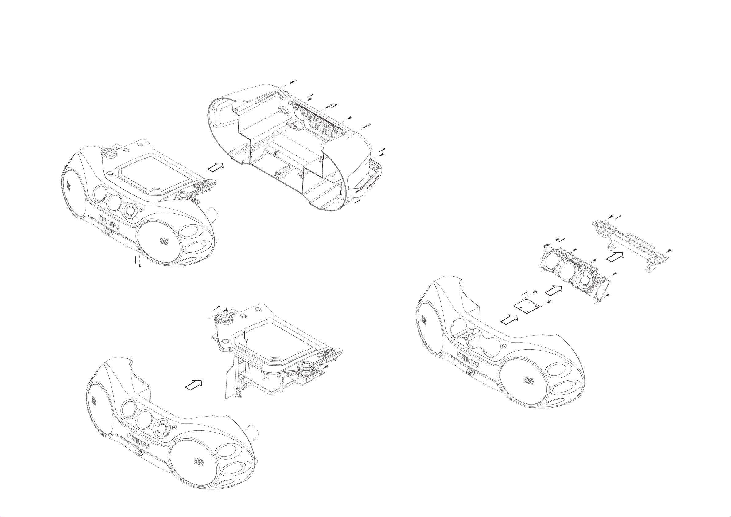
DISASSEMBLY DIAGRAM
A. REMOVE REAR CABINET ASSEMBLY
- REMOVE SCREWS A1 (3X20) 10 PCS
- REMOVE SCREWS A2 (3X12) 4 PCS
- REMOVE SCREW A3 (3X5) 1PS
(UNDER FRONT CABINET ASSY)
A1 (x10)
A2 (x4)
C. REMOVE USB BOARD
- REMOVE SCREWS C6 (3X10) 4 PCS
- REMOVE CASSETTE BRACKET
- REMOVE SCREWS C7 (3X10) 6 PCS
- REMOVE MCU BOARD
- REMOVE SCREWS C8 (2.5X10) 2PCS
- REMOVE USB BAORD
C6 (x4)
A3 (x1)
B. REMOVE CD TRAY ASSEMBLY
- REMOVE SCREWS B4 (3X10) 2PCS
- REMOVE SCREWS B5 (3X8) 2PCS
(IN CD DOOR)
C7 (x6)
C8 (x2)
B4 (x2)
B5 (x2)
Page 10
5 - 1 5 - 1
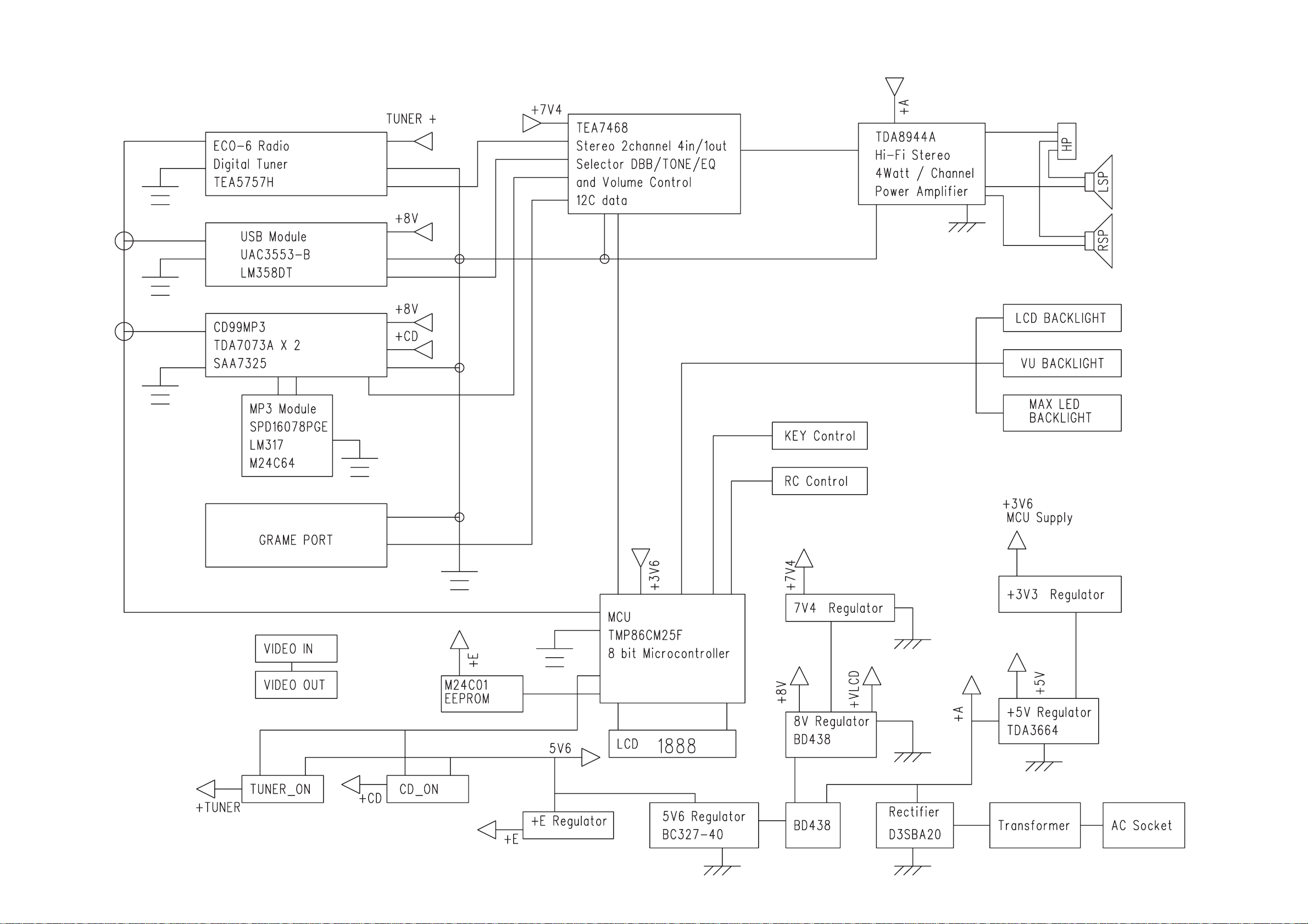
BLOCK DIAGRAM
Page 11
5 - 25 - 2
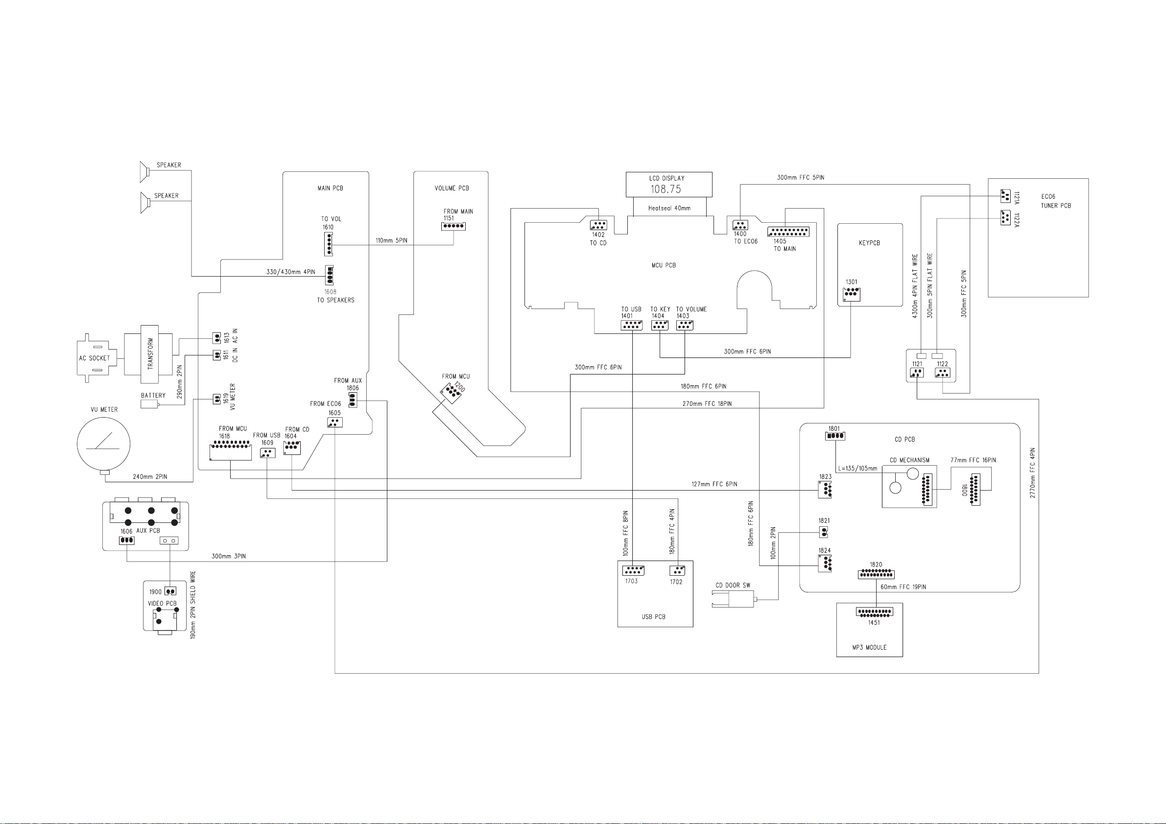
WIRING DIAGRAM
Page 12
6 - 16 - 1
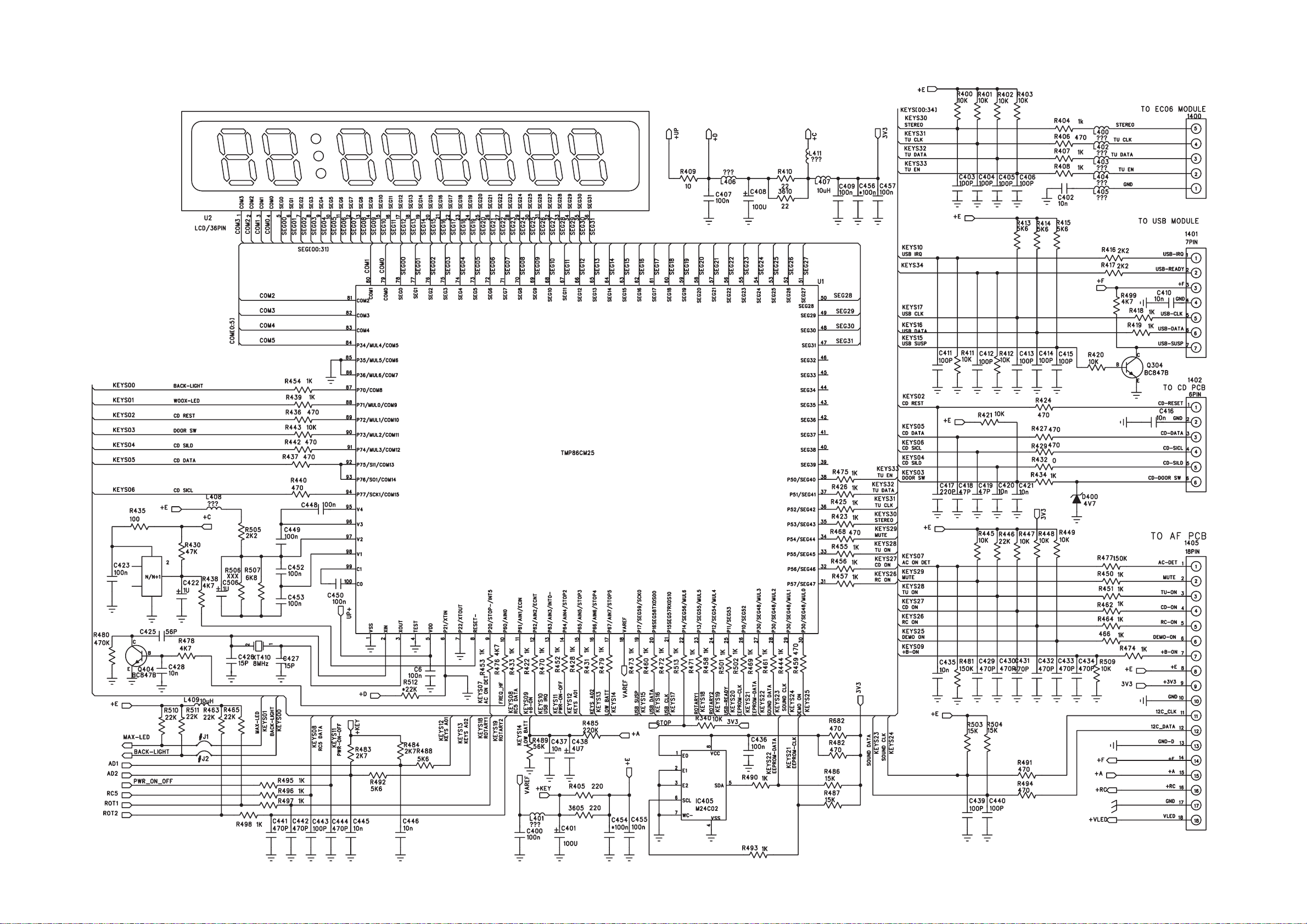
MCU BOARD - CIRCUIT DIAGRAM PART 1
Page 13
6 - 2 6 - 2
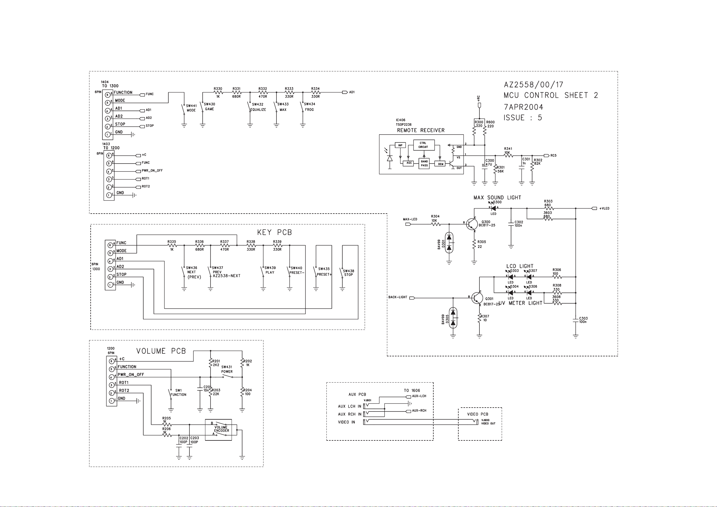
MCU BOARD - CIRCUIT DIAGRAM (PART 2)
Page 14
6 - 3 6 - 3
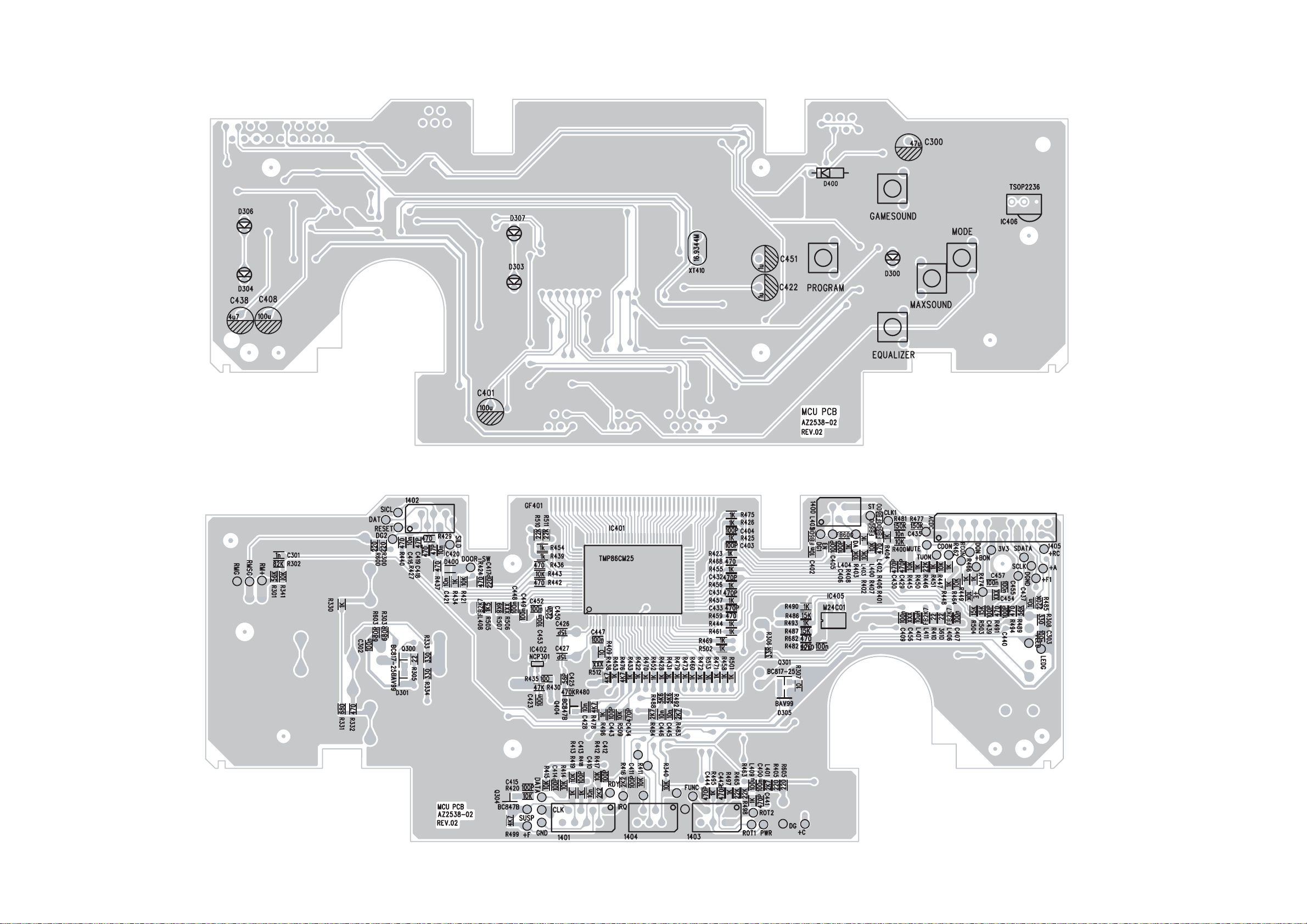
MCU BOARD - LAYOUT DIAGRAM
Page 15
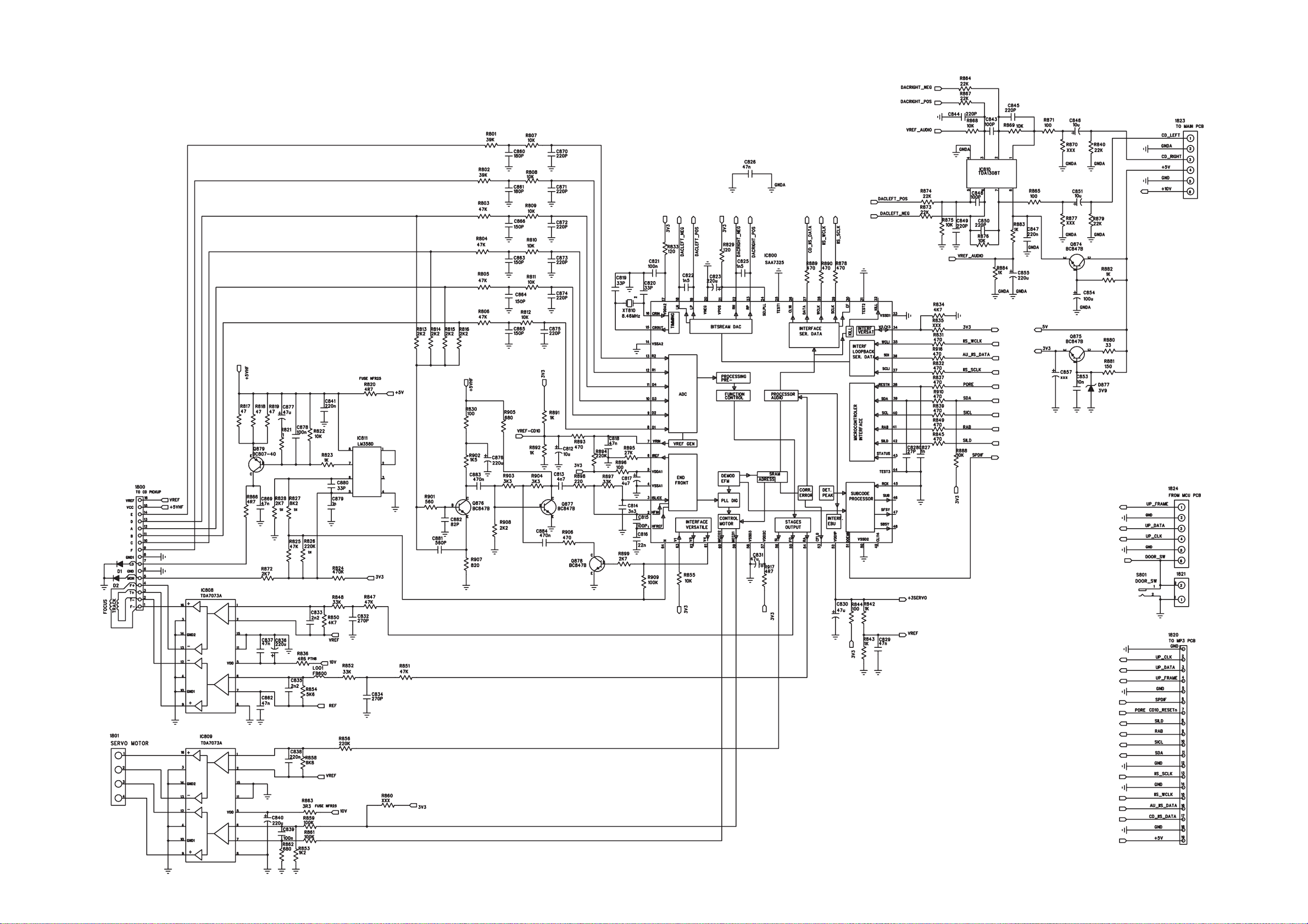
7 - 17 -1
CD BOARD - CIRCUIT DIAGRAM
Page 16
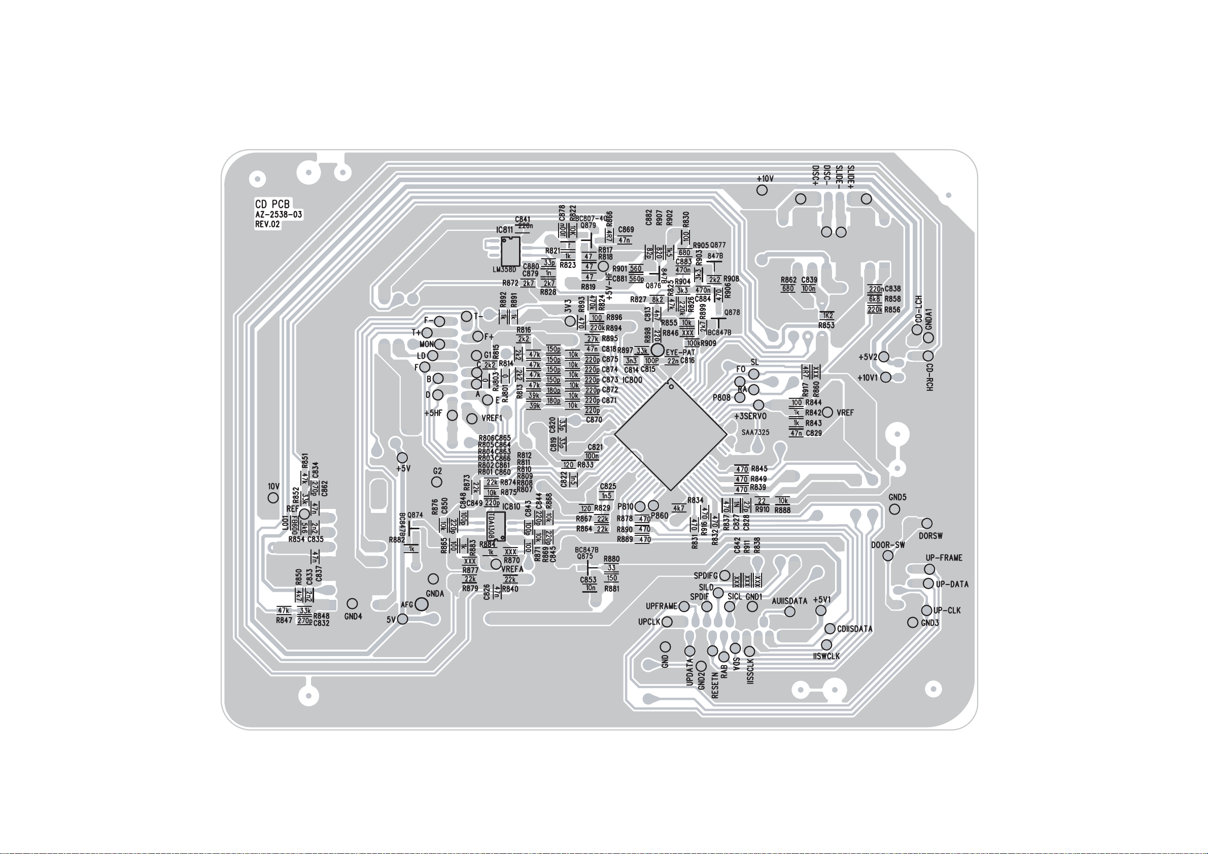
7 - 2 7 - 2
CD BOARD - LAYOUT DIAGRAM
Page 17
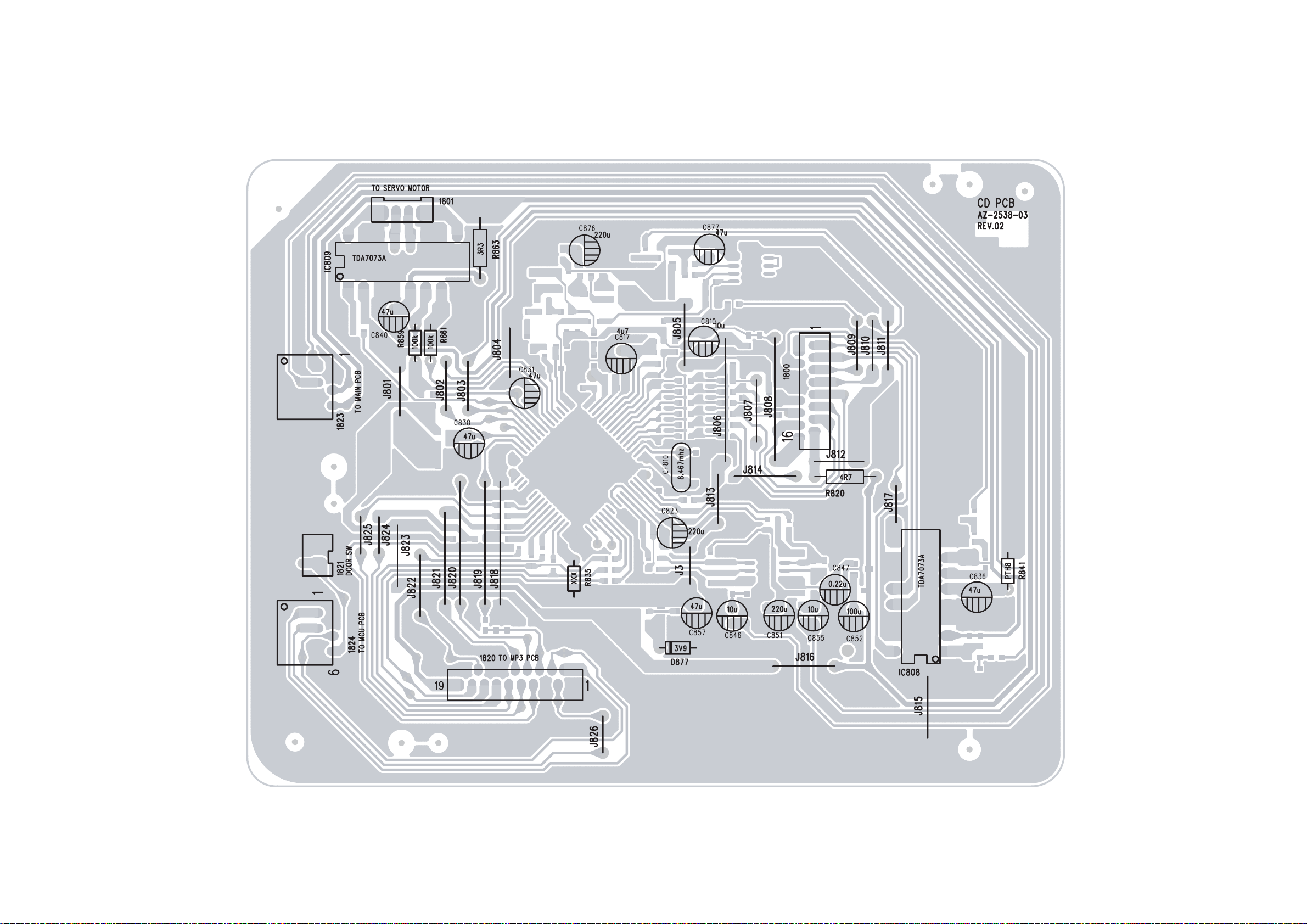
7 - 37 - 3
CD BOARD - LAYOUT DIAGRAM
Page 18
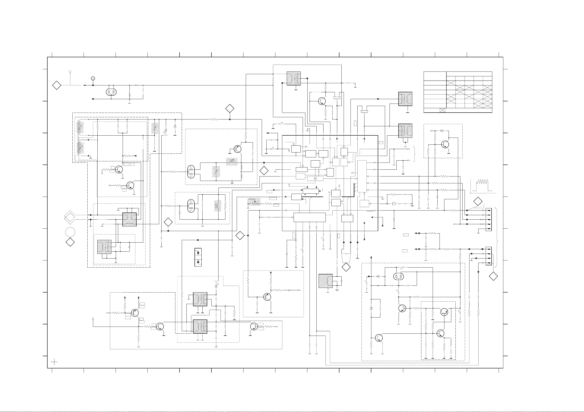
8 - 1 8 - 1
TUNER BOARD - CIRCUIT DIAGRAM
12
TUNER BOARD ECO6
FM
A
A
B
C
D
AM FRAME AERIAL
E
F
G
H
I
1 789
1105
RT-01T
AM-RF
Ferrite Antenna only
blue
black
B
/PORTABLE AUDIO
MW
5104
red
5105
LW
T102
T103
T105
T106
P01
C-PAD
22R
3106
3108
2K2
P01
LW=HIGH
P0
MW=HIGH
Frame Aerial only
*
4101
4102
330k_LW
LW only
LW
5103
6
78
P0
0V
0.7V
*
7PA
34
2
1
LW only
3125
10K
2110
3109
2K2
6103
BAV99
2108
100p
7104
BC337-40
0.7V
0V
5102
6
5
100p
VDD
3123
2111
3107
4M7
2109
4K7
3.9V
3.3V
LW=HIGH
2104
100p
Printed
LW only
33p
Vref
0V1.4V
7105
BC337-40
0V
MW
7KL
78
10p
VDD
1
2
34
4.1V
4.0V
BC857B
7109
0V
4.0V
3180
2101
4109
10K
3128
2K2
47p
2106
*
0V
0.7V
11p
4110
1
HN1V02H
20p_LW frame
7
3101
33K
1
T111
1u
2107
0V
7122
BC847C
p
6106
BAS216
6105-1
2
3102
100K
FM-OSCILLATOR
2152
3132
FM-RF
6131
1SV228
6130
1SV228
33n
560p E_EU
T110
6105
1
2
3
4
HN1V02H
AM-OSCILLATOR
5123
47R
6
5122
*
4104
6
2153
78
78
8
7
6
5
MW
LW
15p
12p E_EU
34
2
1
34
2
1
3105
220R
2155
2p2 J
5130
3
6105-2
5
2120
p
2119
2123
2122
11p
USA
3181
6
HN1V02H
18p
22p_LW
2125
10p
*
2124
390p
3n3
23456
C
T109
Q-multiplier
5131
8K2
2159
560p
3134
22n
33p
5
22K
3103
0.6V
7102
BF550
0V
Printed
Printed
3142
VCO
7124
BC847C
78
AM-IF1
5111
4
T115
6
330R
3104
2128
10u
8K2
RDS only
3176
0V
2103
T112
33K
100K
1n
2149
2126
0.7V
0.1V
0.7V
T128
33p
D
330p
2V
Vref
1.3V
15K
3141
56K
2127
220n
3137
2165
100n
2V
2129
1
100u
2
0V
3
0V
4
5
0V
6
0V
VCC1
7
3.5V
3.5V
8
4.5V-8V
1V-8V
9
1V
1.3V
10
0.7V
11
1.2V
VCC1
22K
3143
3144
1K
7103
BC857C
MPX
BUFFER AMPLIFIER
P0
MW=HIGH
7101
TEA5757H
AM DET
RIPPLE
AM-RF
FM-RF
RF-GND1
FM-OSC
AM-OSC
VCC1
I-TUNE
VCO
AF-OUT
MPX-IN
2131
2169
2n2
RIPPLE
CHARGE
0.8V
470n
AGC
CTRL
PUMP
450kHz
3
T113
2
1
78
0.8V
0.6V
43 39
44
AGC
FM-IN
RF-GND2
AM-IF
AM
FRONTEND
FM
FRONTEND
FM
OSC
PRE-
SCALER
VSTABA
STABILIZER
VCC2
STEREO
DECODER
LEFT
MUTE
LPF
12
13
0.6V
0.8V
0.15V
470n
2132
1u
2133
2K2
3145
MPX
to 1122
pin 2
2134
4105
J
7119
BFS20
1.3V
42
41
AM-IF1-IN
AM
MIXER
AM
OSC
MULTI-
PLEXER
VSTABB
VDD
RIGHT
15
0.6V
2138
DISCRIMINATOR
5119
4
6
22n_USA15n
22n_USA
2135
15n
J
330R
3119
J
1K
3113
1.4V
40
AM-MIXOUT
AGC
FM
MIXER
AGC
PILOT
FILTER
16
1V
2u2
78
FM-IF1
5109
1
I3O
G
J
100p
2112
1V
FM-MIXOUT
AM
IF
AM
DET
FM
DET
IF-GND
1714
2139
3
2
1
2
1.4V
38
VSTABA
AGC
FM-DEMOD
18
1V
0V
15p
2140
103 456 9
2150
100n
FM-IF2
5110
I1O
2
G
0.9V
1.4V
1.4V
0.6V
0.7V
37
FM-IF1-IN
FM
IF1
FM
IF2
CONTROL
AM-IF2
AGC
34
36
35
FM-IF2
VSTABB
CONTROL
XTAL
OSC
AFC-
1.1V
T141
2164
470n
AFC
19
AFC+
1.1V
T142
20
VCC2
FIELDSTR-IND
21
2V
11.4V
VCC2
T116
100n
2141
22
2
82p
2195
0.5V
10 11
3
FM-IF2-IN
WRITE-EN
DIG-GND
MONO/
STEREO
VDD
11.4V
VCC2
T117
6183
3196
T114
1V
0.7V
33
AM-AFC
32
1.4V
P1
31
4.3V
P0
30
3.4V
0V
29
28
DATA
0V
0V
27
CLOCK
26
25
1.4V
24
stereo 0.2V
mono 4.8V
23
VDD
VOLTAGE MULTIPLIER
6182
BAS216
2194
22u
7V
1n
10n
2197
BZX284-C11
0.1V
7182
BC847C
10K
11
4.7V
DT-381
2193
1n
BC847C
p
2161
3169
150K
5121
2145
5.2V
7183
3
2
1
3
2
1
75K
2191
AM-IF2
5112
7P
AM-AFC
5114
7P
100n
LW
Hz
220p
2190
7.5V
78
7
2163
2166
1n
2167
12p
4.7V
4.1V
3.9V-LW
3.5V
3.4V
22u
BAV99
22u
12 13 14
VERSION PROGRAMMING COMPONETS
450kHz
450kHz
100n
VCC1
6181
2192
1n
0V
8
VDD
2196
3190
4
6
4
6
P1
P0
3188
10n
3189
10K
/00 /02 FM/MW/LW
/00 /02 FM/MW
/01 FM/MW
/14 FM-OIRT/MW
/17 FM/AM
/06 JAPAN
VERSION DETECTION
3170
PROGR.
OUTPUT PORTS
2n2
2148
2147
T118
2144
T140
2130
2K2
22K
2187
4K7
3191
2188
VERSION
P1
3156
100K
3157
3160
470R
220p
3155
47R
470n
3167
47R
470n
0.1V
3187
10n
3192
0.1V
10n
3195
6120
component mounted
6120
BAS216
100K
100K
3161
22K
3159
470R
220p
2146
MPX
from 2169
3166
47R
OSCILLATOR
7180
BC857B
1K
4.8V
1M
4.8V
7181
BC847C
0.5V
470K
3194
100K
7111
BC847C
3158
470R
5.4V typ.
(5V-12V)
5.4V
3193
2189
3156
3186
2186
2K2
220n
12 13
180R
220u
T123
T122
T121
T120
3157
5V
0V
0V
0V
ENABLE/MPX
0V
T127
T126
2137
3153
3170
152 kHz, 50mVpp
3
STEREO
CLOCK
DATA
VCC
RIGHT
T125
GND
LEFT
T124
2136
220n
3152
470R
monostereo
220n
470R
14
7111
stereo
stereo 0.3V
mono 4.8V
1122
5
4
3
2
1
1121
4
3
2
1
1105 A1
1121 F14
1122 E14
2101 A3
2103 C7
2104 A3
2106 B4
2107 F4
2108 F3
2109 F3
2110 B3
2111 B3
2112 B9
A
2119 H6
2120 H6
2122 I6
2123 I6
2124 I6
2125 H6
2126 E7
2127 E7
2128 B8
2129 C7
2130 F12
2131 F8
B
2132 F8
2133 F8
2134 I9
2135 I9
2136 H14
2137 H14
2138 F9
2139 G9
2140 G10
2141 F10
2144 F12
C
2145 E11
2146 D13
2147 E12
2148 D12
2149 H7
2150 A10
2152 E4
2153 E5
2155 D5
2159 F6
2161 C11
2163 D11
D
2164 F10
2165 C7
2166 D12
2167 E12
2169 G8
2186 H13
2187 H12
2188 I12
2189 I13
2190 G12
2191 H11
2192 G12
E
2193 G11
2194 G11
2195 G10
2196 H12
2197 H11
3101 E4
3102 D4
3103 C7
3104 A7
3105 B6
to/from
4
3106 B2
F
3107 C3
3108 D2
3109 D3
3113 B9
3119 A9
3123 H3
3125 H3
3128 I4
3132 H5
3134 H6
3137 I7
3141 E7
G
3142 E7
3143 G7
3144 G8
3145 F8
3152 H14
3153 H14
3155 F12
3156 C12
3157 C12
3158 E13
3159 D13
3160 D13
H
3161 D13
3166 F13
3167 F12
3169 D11
3170 C12
3176 G7
3180 I3
3181 E6
3186 F13
3187 H12
3188 H12
I
3189 H12
3190 H12
3191 I12
3192 I12
3193 I13
3194 I13
3195 I12
3196 I10
4101 E2
4102 E2
4104 I5
4105 A9
4109 C3
4110 C4
5102 E3
5103 F2
5109 A9
5110 B10
5111 A8
5112 A11
5114 B11
5119 G9
5121 E11
5122 H5
5123 G5
5130 E6
5131 C6
6103 A3
6105-1 B4
6105-2 G6
6106 B4
6120 B13
6130 D5
6131 C5
6181 G12
6182 G11
6183 H10
7101 B8
7102 C7
7103 H7
7104 D3
7105 D3
7109 H3
7111 C13
7119 A9
7122 I4
7124 I7
7180 H13
7181 I13
7182 I11
7183 H11
T102 A2
T103 A2
T105 E2
T106 E2
T109 B6
T110 F5
T111 F4
T112 F7
T113 A9
T114 A11
T115 A8
T116 F10
T117 G10
T118 F12
T120 E14
T121 E14
T122 E14
T123 E14
T124 G14
T125 F14
T126 F14
T127 F14
T128 C7
T140 F12
T141 F10
T142 F10
Page 19
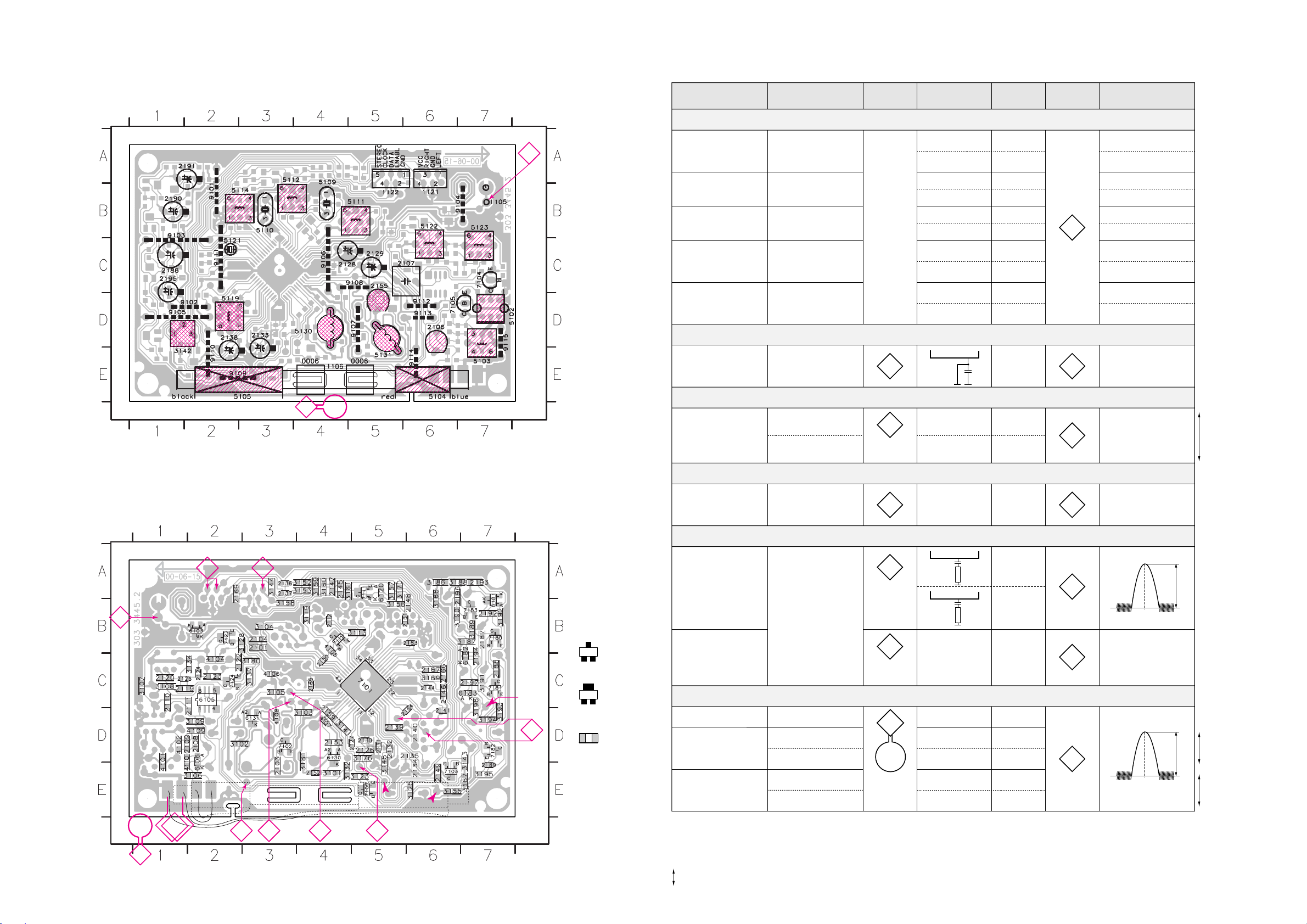
8 - 28 - 2
These assembly drawings show a summary of all possible versions.
For components used in a specific version see schematic diagram respectively partslist.
ECO6 PA 34450 stage .2, 110700
41..
in schematic diagram)
(not all items shown
SMD jumper
EB
C
A
K
123
4
34125
black
black
red
red
LWMW
blue
5104 5105
2101 B3
2103 E3
2104 B3
2108 D2
2109 D1
2110 C1
2111 C2
2112 B4
2119 C1
2120 C1
2122 C2
2123 C2
2124 C2
2125 C1
2126 D5
2127 D5
2130 D5
2131 D5
2132 D5
2134 E6
2135 D6
2136 A3
2137 A3
2139 D5
2140 D6
2141 D6
2144 C6
2145 A4
2146 C6
2147 A4
2148 B6
2149 E6
2150 C4
2152 E4
2153 D4
2159 D4
2161 B5
2163 B6
2164 D6
2165 C4
2166 C6
2167 C6
2169 A2
2187 B7
2188 C7
2189 E7
2192 B7
2193 A7
2194 C7
2196 A6
2197 C7
3101 E4
3102 D2
3103 D4
3104 B3
3105 C3
3106 E2
3107 C1
3108 C1
3109 D2
3113 B5
3119 B5
3123 E5
3125 E6
3128 B2
3132 E4
3134 C2
3137 C3
3141 D4
3143 D7
3144 A3
3145 E5
3152 A4
3153 A4
3155 E6
3156 B5
3157 A5
3158 B3
3159 A4
3160 A4
3161 A4
3166 B6
3167 E7
3169 C6
3170 A5
3176 D5
3180 C3
3181 D4
3186 A6
3187 B7
3188 A6
3189 B7
3190 B6
3191 C7
3192 B7
3193 D7
3194 D7
3195 E7
3196 C7
4101 D1
4102 D1
4104 C2
4105 B4
4106 C3
4107 D4
4108 D3
4109 D2
4110 D1
6103 B2
6105 C2
6106 D2
6120 A5
6130 D4
6131 D3
6181 B7
6182 C7
6183 C7
7101 C5
7102 D3
7103 E6
7109 E5
7111 A5
7119 B5
7122 B2
7124 C2
7180 B7
7181 C7
7182 D7
7183 B7
TUNER BOARD ECO6 PA /
copperside view
4 3
D
1
A
C
5
2
B
Vcc1
Vcc2
Vdd
ECO6 PA combi layout 34450 stage .2, 110700
1105 B7
1121 B6
1122 B5
2106 D6
2107 C6
2128 C4
2129 C5
2133 D3
2138 D2
2155 C5
2186 C1
2190 B1
2191 A2
2195 C1
3142 E1
5102 D7
5103 E7
5109 B4
5110 B3
5111 B4
5112 B3
5114 B3
5119 D2
5121 C2
5122 B6
5123 B7
5130 D4
5131 E5
7104 C7
7105 D6
9101 B2
9102 D2
9103 B1
9104 B7
9105 D1
9106 C4
9107 D5
9108 C5
9109 E2
9110 E2
9111 C2
9112 D6
9113 D6
9114 E6
9115 D7
TUNER BOARD ECO6 PA /
componentside view
AM-AFC
DISC.
VCO
LW MW
AM-IF2
AM-IF1
FM-IF1
FM-OSC.
LW-OSC.
MW-OSC.
FM-RF
FM-RF
AM-RF
LW-RF
MW-RF
FM-IF2
B
A
TUNER BOARD ECO6 - LAYOUT DIAGRAM
VARICAP ALIGNMENT
FM RF
FM IF
VCO
AM IF
AM RF
3)
108MHz
87.5MHz
(65.81MHz)
87.5MHz
(65.81MHz)
87.5MHz
(65.81MHz)
279kHz
153kHz
1602kHz
531kHz
5130
check
5122
check
5123
check
8V –0.2V
4.3V –0.5V
(1.2V –0.5V)
8V –0.2V
1.1V –0.4V
8V –0.2V
1.1V –0.4V
1494kHz
558kHz
560kHz
1500kHz
5105
LW ferrite coil
198kHz
1494kHz
558kHz
560kHz
1500kHz
198kHz
2106
5104
MW ferrite coil
5104
MW ferrite coil
2106
3142 152kHz –1kHz
1)
98MHz
5112
MAX
FM
87.5 - 108MHz
(65.81 - 74, 87.5 - 108MHz)
LW
153 - 279kHz
MW
FM/MW/LW- version, 9kHz grid
531 - 1602kHz
1700kHz
530kHz
5123
check
8V –0.2V
1.1V –0.4V
1602kHz
531kHz
5123
check
6.9V –0.2V
1.1V –0.4V
108MHz
108MHz 2155
5131
MW
FM/AM-version, 10kHz grid
530 - 1700kHz
FM
MW
LW
98MHz, 1mV
continuous wave
450kHz
connect pin 6 of
IC 7101 (AM Osc.)
with 2.2k‰ to Vcc
Use Service Testprogram. By selecting the TUNER TEST test frequencies will be stored as preset frequencies automatically.
4
1
3
5
5
A
A
5119FM
10.7MHz, 45mV
continuous wave
2D
mod=1kHz
∆f=–22.5kHz
1)
If sensitivity of frequency counter is too low adjust to max. channel separation
(input signal: stereo left 90% + 9%, adjust output on right channel to minimum)
Repeat
ECO6, general with ferrite antenna, 070799
TUNER ADJUSTMENT TABLE ( ECO6 FM/MW- and FM/MW/LW - versions with ferrite antenna)
∆f=–10kHz
VRF = 0.5mV
C
see
remark
2)
220R
100nF
36
IC 7101
220R
100nF
40
IC 7101
2141
shortcircuit
to block AFC
21
IC 7101
max.
symmetric
f
o
AM AFC
MW
C
continuous wave
VRF = 2mV
5111
5114
2
0 – 2 mV DC
0 – 3 mV DC
MW
FM/MW/LW- and FM/MW-version
( 9kHz grid)
531 - 1602kHz
B
∆f = –30kHz
VRF as low as
possible
max.
symmetric
f
o
MW
FM/AM-version, 10kHz grid
530 - 1700kHz
2)
RC network serves for damping the IF-filter while adjusting the other one.
3)
LW has to be aligned before MW.
Waverange Input frequency Input Tuned to Adjust Output Scope/Voltmeter
FM
87.5 - 108MHz
(65.81 - 74, 87.5 - 108MHz)
FM/MW-version, 9kHz grid
531 - 1602kHz
(as low as
possible)
Page 20
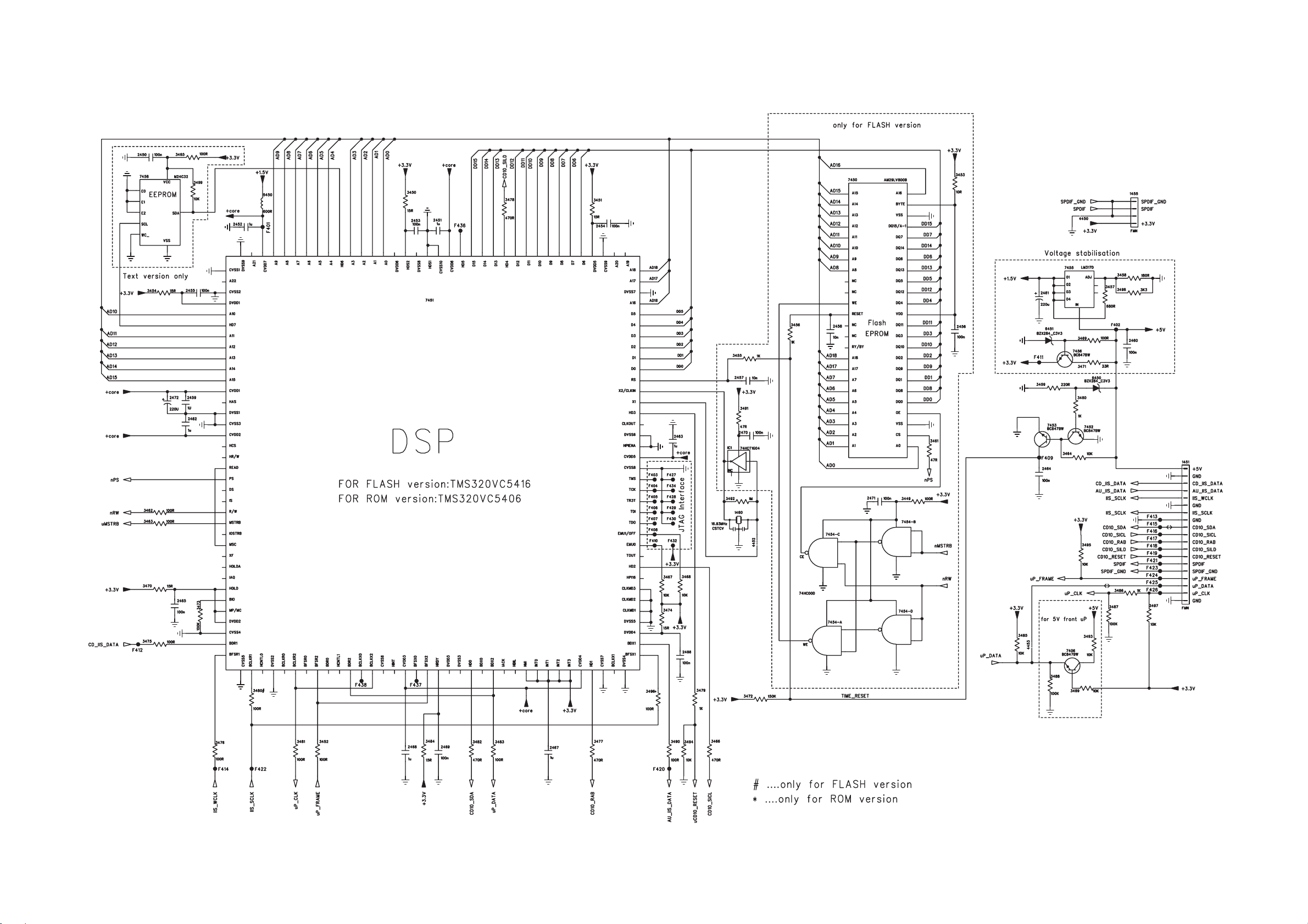
9 - 1 9 - 1
MP3 BOARD - CIRCUIT DIAGRAM
Page 21
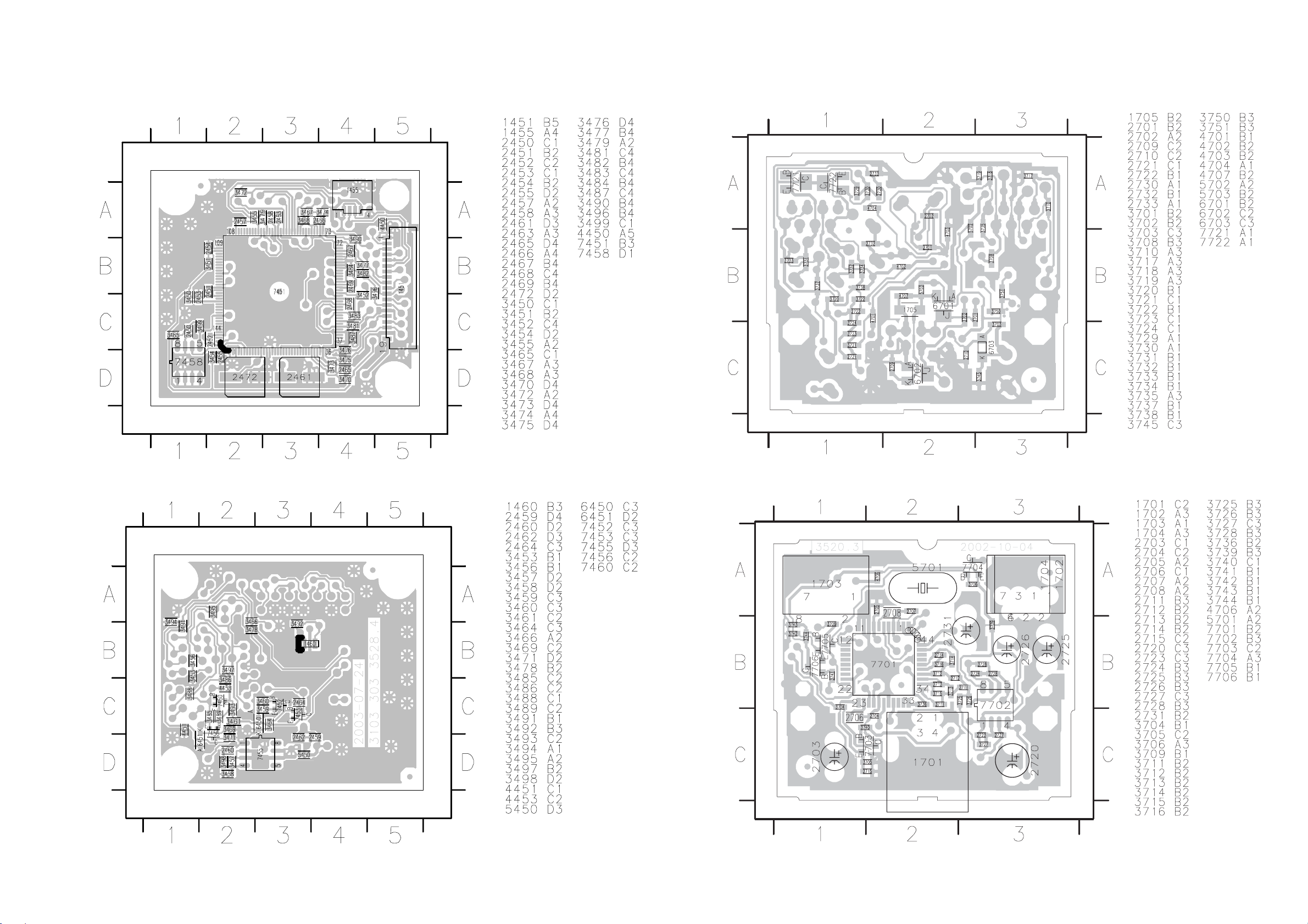
9 - 29 - 2
MP3 BOARD - LAYOUT DIAGRAM USB BOARD - LAYOUT DIAGRAM
Page 22
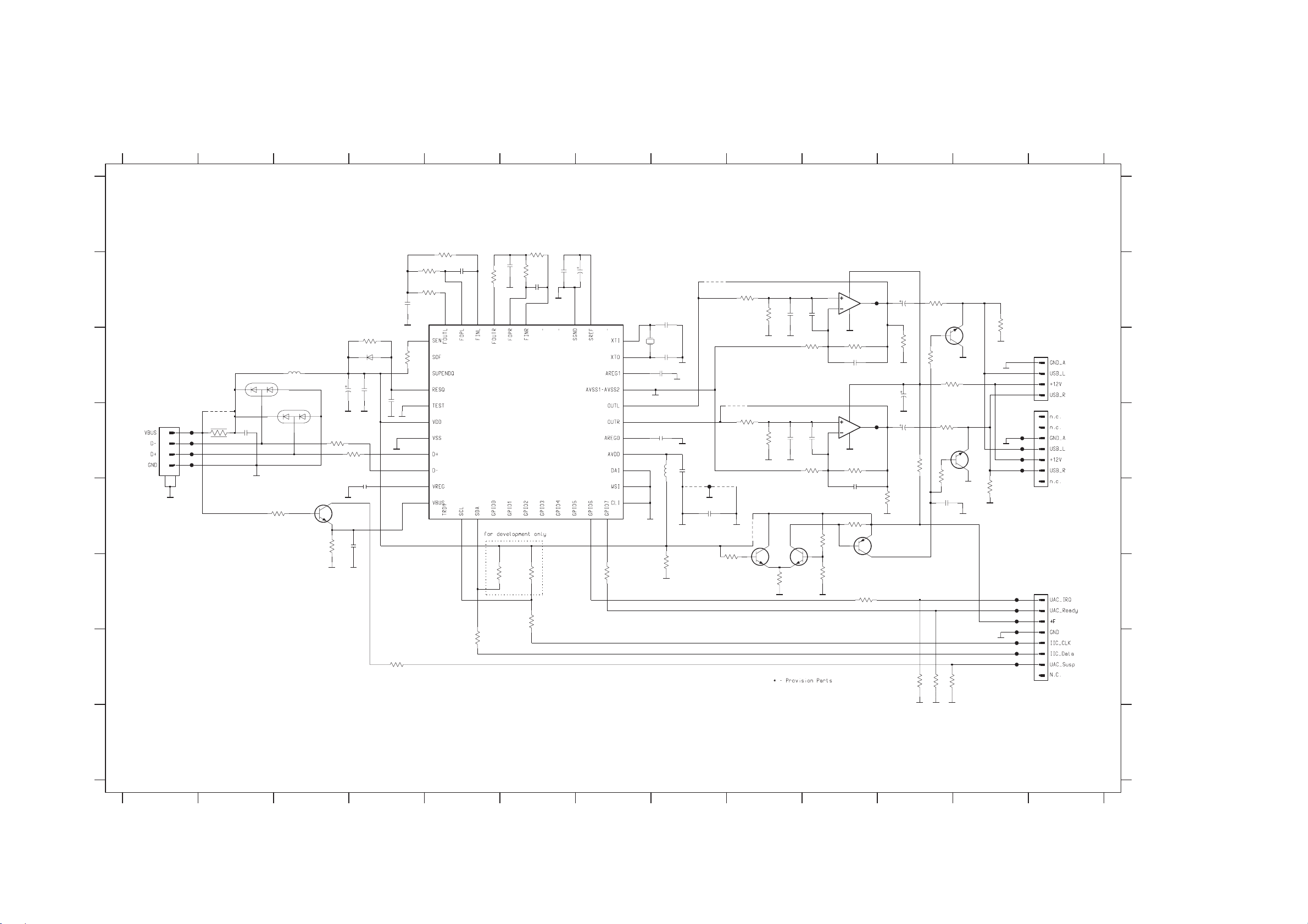
10 - 1 10 - 1
USB BOARD - CIRCUIT DIAGRAM
12
34567891011 12 13
A
2712
12K
GND_A1
4K7
3714
12K
1n0
12K
3716
2714
220p
GND_A1
4K7
3751
3709
220R
2732
100n
2731
35V4u7
2701
5701
2707
220n
GND_A1
2708
470n
22p
AT-49
2702
22p
5702
3745
12M
GND_A1
GND_A1
GND_A1
2M2
3708
1
2
3
5
6
7
8
9
10
11
12131415161718
220R
2705
220n
4703
4701
F716
GND_A1
2733
10n
*
4704
GND_AF
3741
470K
4702
*
3721
*
3722
10K
10K
*
4706
7706
BC847B
3723
GND_AF
3724
GND_AF
10K
GND_AF
10K
GND_AF
3742
2721
2722
47K
330p
330p
7705
BC847B
3725
10K
3726
10K
2727
2728
100p
100p
3744
3743
3
2
5
6
27K
100K
8
4
GND_AF
3727
10K
2723
330p
8
4
GND_AF
3728
10K
2724
330p
3706
47K
7702-1
LM358D
7702-2
LM358D
3735
220R
1
F717
7
F718
BC857B
7704
3738
GND_AF
2725
35V 4u7
3737
GND_AF
2720
GND_AF
2726
4u735V
3K3
3731
470R
47K
BC817-25
7722
GND_AF
GND_AF
3734
3733
GND_AF
GND_AF
47K
F709
F710
F711
F712
F713
F714
F715
F705
F707
F706
F708
1704
1
2
3
4
1702
1
2
3
4
5
6
7
1703
FE-ST-VK-N
1
2
3
4
5
6
7
8
FFC
FE-ST-VK-N
BC817-25
3K3
3729
16V22u
7721
2K2
GND_AF
3720
330R
3732
470R
*
3739
100R
2K2
3730
GND_AF
2730
10n
GND_AF
22K
47K
22K
3718
3719
3717
3713
12K
3715
2711
GND_A1
3736
220n
3711
1n0
33
32
10K
31
30
29
28
27
26
25
24
23
B
3703
220K
6703
3701
22R
7703
BC847B
150K
2703
3702
22R
2715
35V
4u7
BAS316
2704
2706
470n
470p
220n
2710
C
*
1701
USB
D
56
4707
1705
2R2
F701
1
F702
2
F703
3
F704
4
2709
100n
E
6701
BAV99
5703
6702
BAV99
3740
470K
3705
2713
12K
220p
12K
34 35 36 37 38 39440 41 42 43 44
7701
QFP44
202122
3712
19
3750
F
3710
220R
G
3704
1K0
H
1701 D1
1702 D13
1703 F13
1704 C13
1705 D2
2701 B8
2702 C8
2703 C3
2704 C4
2705 D8
2706 E4
A
2707 C8
2708 D8
2709 D2
2710 C4
2711 B4
2712 B6
2713 B5
2714 B6
2715 E4
2720 C11
2721 B9
B
2722 D9
2723 C10
2724 E10
2725 B11
2726 D11
2727 B10
2728 D10
2730 E11
2731 B7
2732 B6
2733 E8
3701 D3
C
3702 D4
3703 C4
3704 G4
3705 E3
3706 E10
3708 F7
3709 F6
3710 G5
3711 B5
3712 B5
3713 A5
3714 A6
D
3715 B5
3716 B6
3717 G11
3718 G11
3719 G11
3720 C11
3721 B9
3722 D9
3723 B9
3724 D9
3725 C10
E
3726 D10
3727 C10
3728 D10
3729 C11
3730 D11
3731 B11
3732 D11
3733 B12
3734 E12
3735 F10
3736 C4
3737 C11
F
3738 E11
3739 D11
3740 E3
3741 E9
3742 F9
3743 F10
3744 E10
3745 F8
3750 F5
3751 F6
4701 B8
4702 D9
G
4703 E8
4704 E8
4706 E9
4707 D2
5701 C7
5702 D8
5703 C3
6701 C2
6702 D3
6703 C4
7701 D5
H
7702-1 B10
7702-2 D10
7703 E3
7704 E10
7705 F10
7706 F9
7721 C12
7722 D12
F701 D1
F702 D1
F703 D1
F704 D1
F705 D12
F706 D12
F707 D12
F708 D12
F709 F12
F710 F12
F711 F12
F712 F12
F713 G12
F714 G12
F715 G12
F716 E8
F717 B10
F718 D10
123456789101112
13
Page 23
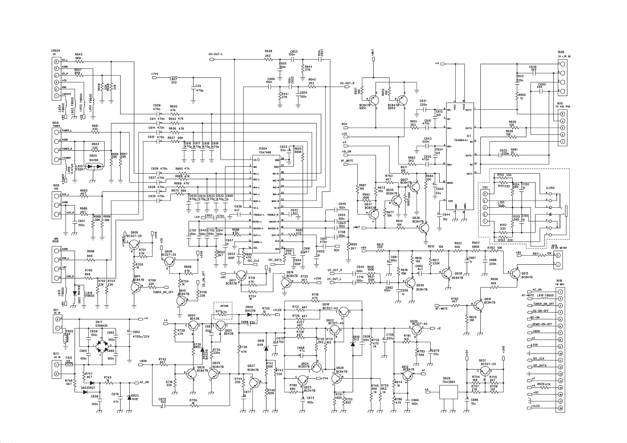
11- 111 - 1
MAIN BOARD - CIRCUIT DIAGRAM
Page 24
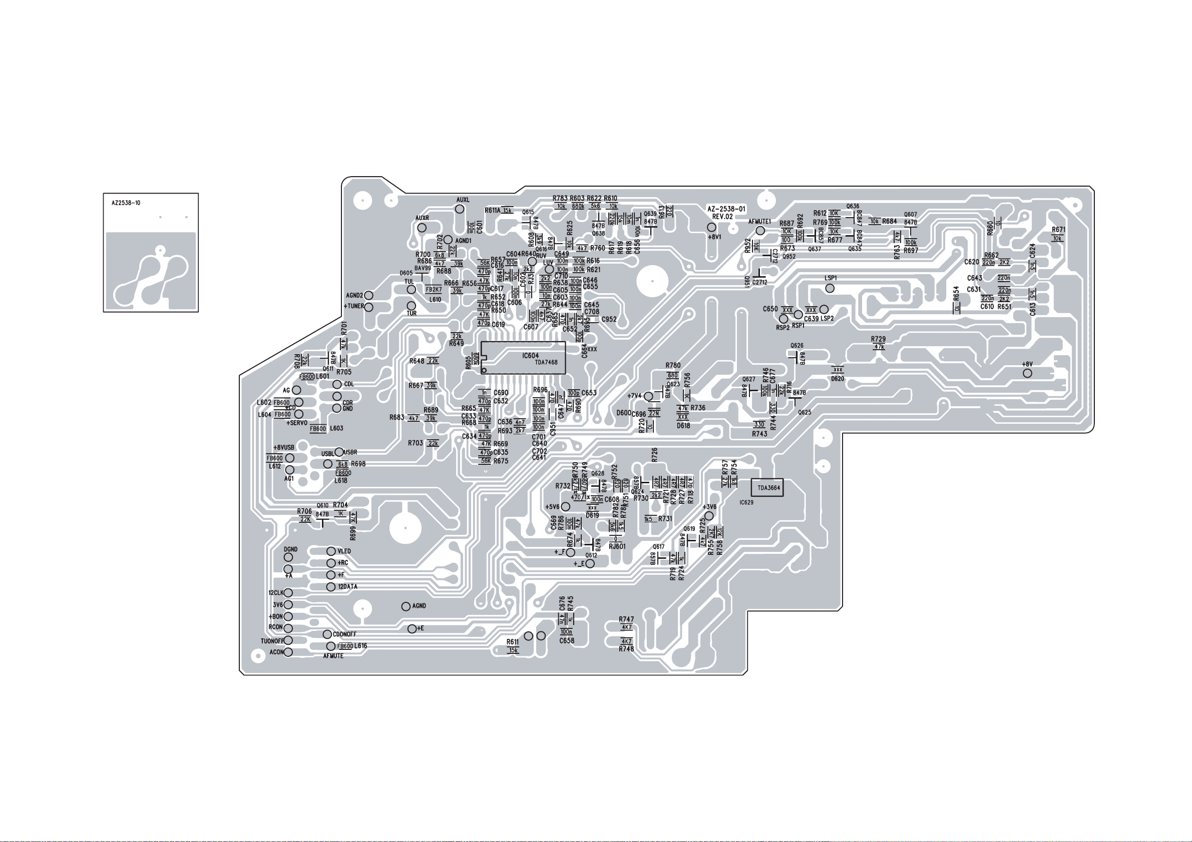
11 - 2 11 - 2
MAIN BOARD - CIRCUIT DIAGRAM
Page 25
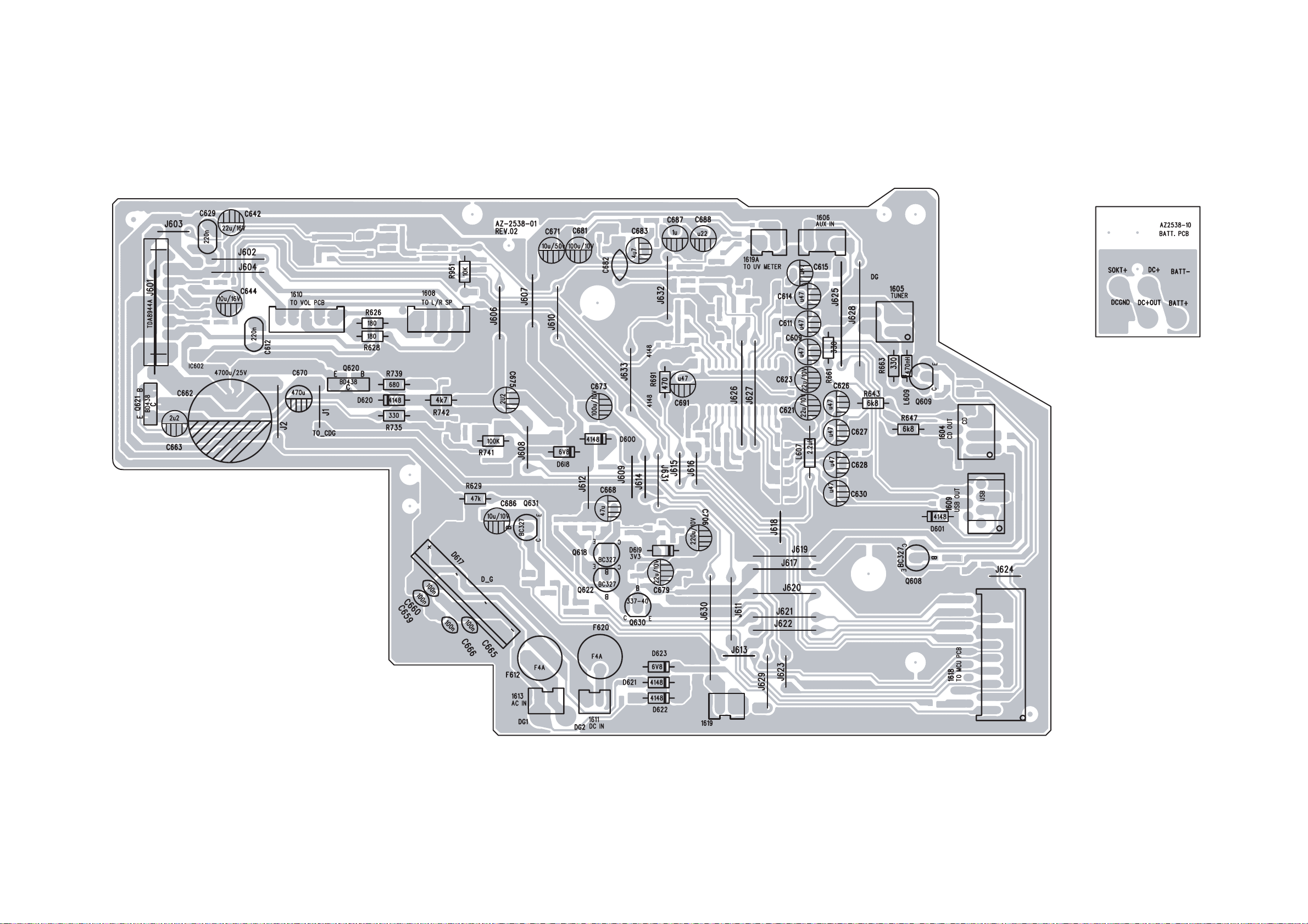
11 - 311 - 3
MAIN BOARD - CIRCUIT DIAGRAM
Page 26
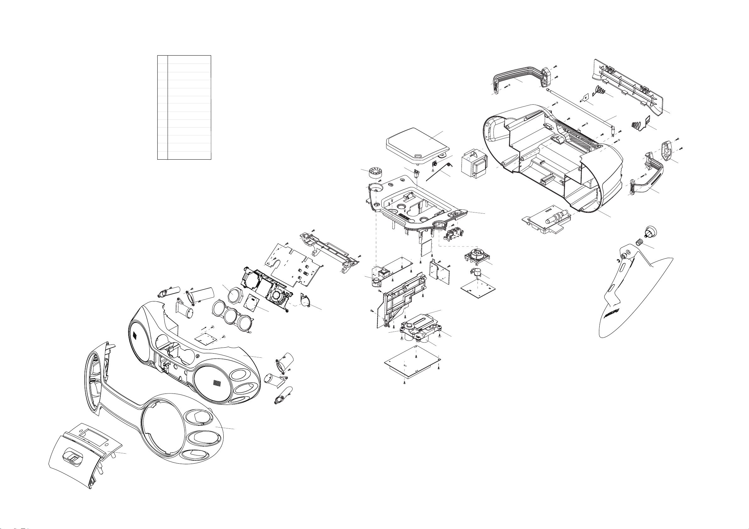
12 - 1 12 - 1
SCREW LIST :
M2x6
T2 x 8
T2 x 10
T2.5 x 10
T3 x 8
T3 x 10
T3 x 12
T3 x 16
T3 x 20
T3 x 32
C P/W 2.5 x 10
T P/W 3 x 10
T P/W 3 x 16
1
2
3
4
5
6
7
8
9
0
!
@
#
! (x2)
7 (4x)
9
(4x)
9
(2x)
9
(2x)
9
(2x)
6
(2x)
5
(7x)
5
(2x)
6
(4x)
6 (3x)
6
(4x)
6
(4x)
6 (6x)
5
(4x)
5
(4x)
5
(3x)
! (4x)
5
(2X)
6
(2x)
419
403
407
411
409
412
413
414
408
404
423
421
13
(2x)
!
401
402
405
406
422
432
433
434
431
428
427
424
426
429
425
6
416
417
418
EXPLODED VIEW DIAGRAM - CABINET
Page 27

12 - 212 - 2
MECHANICAL PARTSLIST
ELETRICAL PARTSLIST
401 994000000534 CASS. DOOR (USB)
402
403
404
405
406
407
408
409
411
412
413
414
416
417
418
419
421
423
424
994000000531 FRONT PANEL
994000000529 FRONT CABINET
314011051882 VU METER
994000000514 LCD DISPLAY
994000000537 MAX KNOB
994000000518 CUSHION : 658B (40)(GREEN)
994000000515 CD DECK : DA12B3PH (SANYO)
994000000517 CUSHION : 658A (30)(RED)
994000000516 DUST COVER : SK-09
994000000542 PLAY KNOB
994000000538 KEYSET PRESET
994000000539 STANDBY KEY
994000000541 SOURCE KEY
994000000536 CD TRAY
994000000543 VOLUME KNOB
313911873620 DAMPER ASS'Y MODULE 0.8
994000000548 CD DOOR SPRING
994000000535 CD DOOR
994000000551 BATTERY SPRING (-)
994000000522 MAIN BOARD ASSY
994000000523 MCU BOARD ASSY
994000000524 CD BOARD ASSY
994000000525 EC06 BOARD ASSY
310330866791 MP3 BOARD ASSY
994000000526 TACT SWITCH
994000000527 PUSH LATCH SWITCH
994000000528 STEREO JACK:TC-38-103-01
994000000513 FUSE:19374-4A
314011051882 VU-METER
994000000555 RCA JACK
994000000556 RCA SOCKET
994000000563 AC SOCKET(-/17)
994000000558 AC SOCKET(-/00C/01/05)
994000000557 USB TYPE 4P4C JACK (only for AZ2538)
994000000521
994000000561 TRANSFORMER(-/01)
994000000562 TRANSFORMER(-/17)
994000000554 SPEAKER:4" 16 OHM 8 W MAX
994000000553 VDE POWER CORD SET(-/00C/01)
TRANSFORMER (-/00C/05)
425
426
427
428
429
431
432
433
434
994000000546 HANDLE COVER (R)
994000000552 BATTERY CONTACT PLATE
994000000533 BATTERY DOOR
994000000549 BATTERY SPRING (+-)
994000000519 ROD ANTENNA : YH1959
994000000544 HANDLE
994000000545 HANDLE COVER (L)
994000000532 REAR CABINET : AZ-2538
994000000547 STAND KNOB SPRING
313923806811 REMOTE CONTROL:RC19621011
Note: Only these parts mentioned in the list are
normal service parts.
996500007586 VDE POWER CORD SET(-/05)
242207098246 VDE POWER CORD SET(-/17)
Note: Only these parts mentioned in the list are
normal service parts.
 Loading...