

Philips AZ-2030, AZ-2035 Service manual
CD Stereo Radio Recorder
AZ2030
AZ2035
all versions
TABLE OF CONTENTS
chapter
Handling chip components and safety 1 - 1
Technical Specification & Service Tools 2 - 1
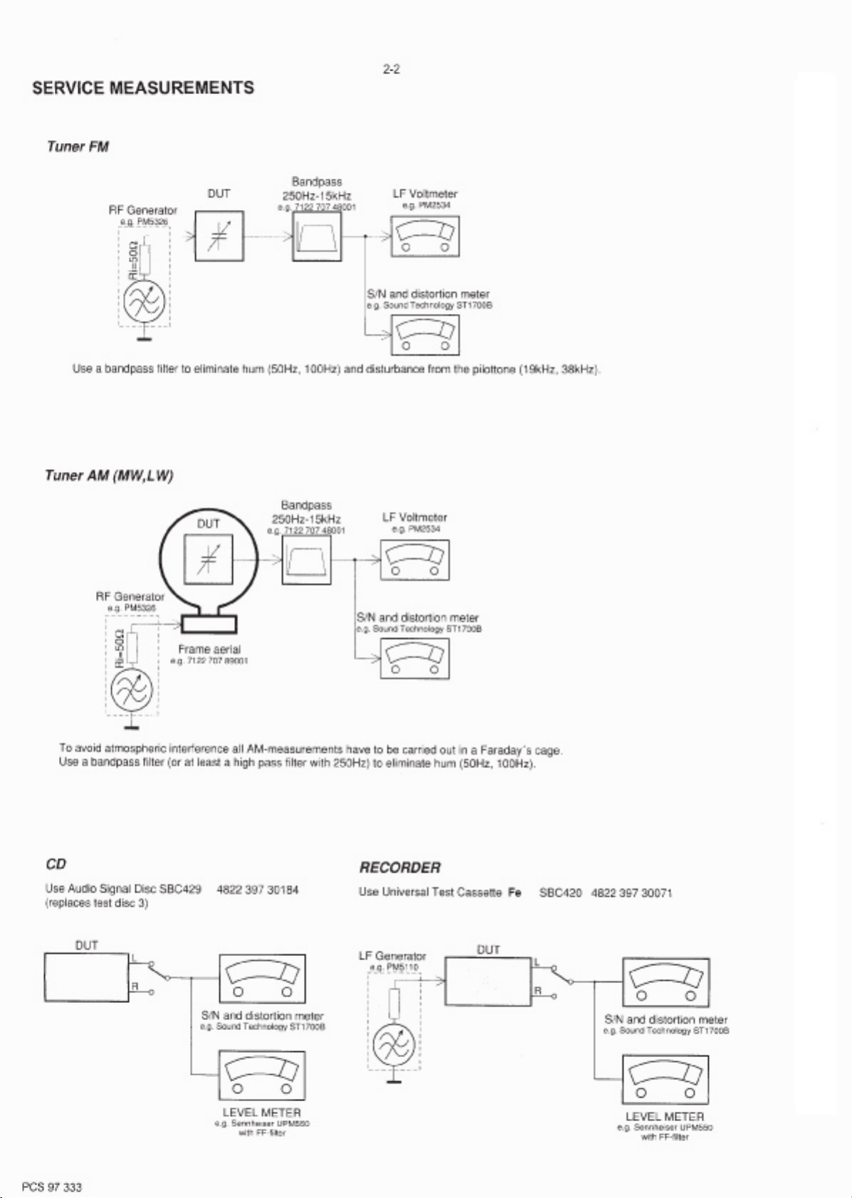
Service Measurement 2 - 2
Connections & Controls
Instructions for use
Disassembly Diagram 4 - 1
CD Service Test Program 4 - 2 to 4 - 3
Block Diagram
Wiring Diagram 5 - 2
FRONT BOARD
circuit diagram
layout diagram
AF & POWER BOARD
circuit diagram
layout diagram
FEATURE BOARD
circuit diagram
layout diagram
..................................................
................................................
.................................................
...................................................
........................................
.............................................................
...........................................................
.......................................................
.......................................................
.......................................................
.......................................................
.......................................................
.......................................................
.............................
..........................
3 - 1
3 - 2 to 3 - 6
5 - 1
6 - 1
6 - 2
7 - 1
7 - 2
8 - 1
8 - 1
TUNER BOARD
circuit diagram
layout diagram 9 - 2
REOCRDER BOARD
circuit diagram 10 - 1
layout diagram 10 - 2
CD MODULE
circuit diagram
layout diagram 11 - 1
EXPLODED VIEWS DIAGRAM
cabinet
tape deck
Mechanical partslist
Electrical partslist
.......................................................
.......................................................
.......................................................
.......................................................
.......................................................
.......................................................
.................................................................
............................................................
.....................................................
...............................................
13 - 1 to 13 - 5
chapter
9 - 1
11 - 2
12 - 1
12 - 2
12 - 2
Safety regulations require that the set be restored to its original
condition and that parts which are identical with those specified
be used.
C
Copyright 1995 Philips Consumer Electroncis B.V. Eindhoven, The Netherlands
All rights reserved. No part of this publication may be reproduced, stored in a retrieval
system or transmitted, in any form or by any means, electronic, mechanical, photocopying,
or otherwise without the prior permission of Philips.
Printed in The Netherlands Copyright reserved Subject to modification
PCS 107 271
CLASS 1
LASER PRODUCT
GB
3140 785 22580Published by SS 0115 Service Audio
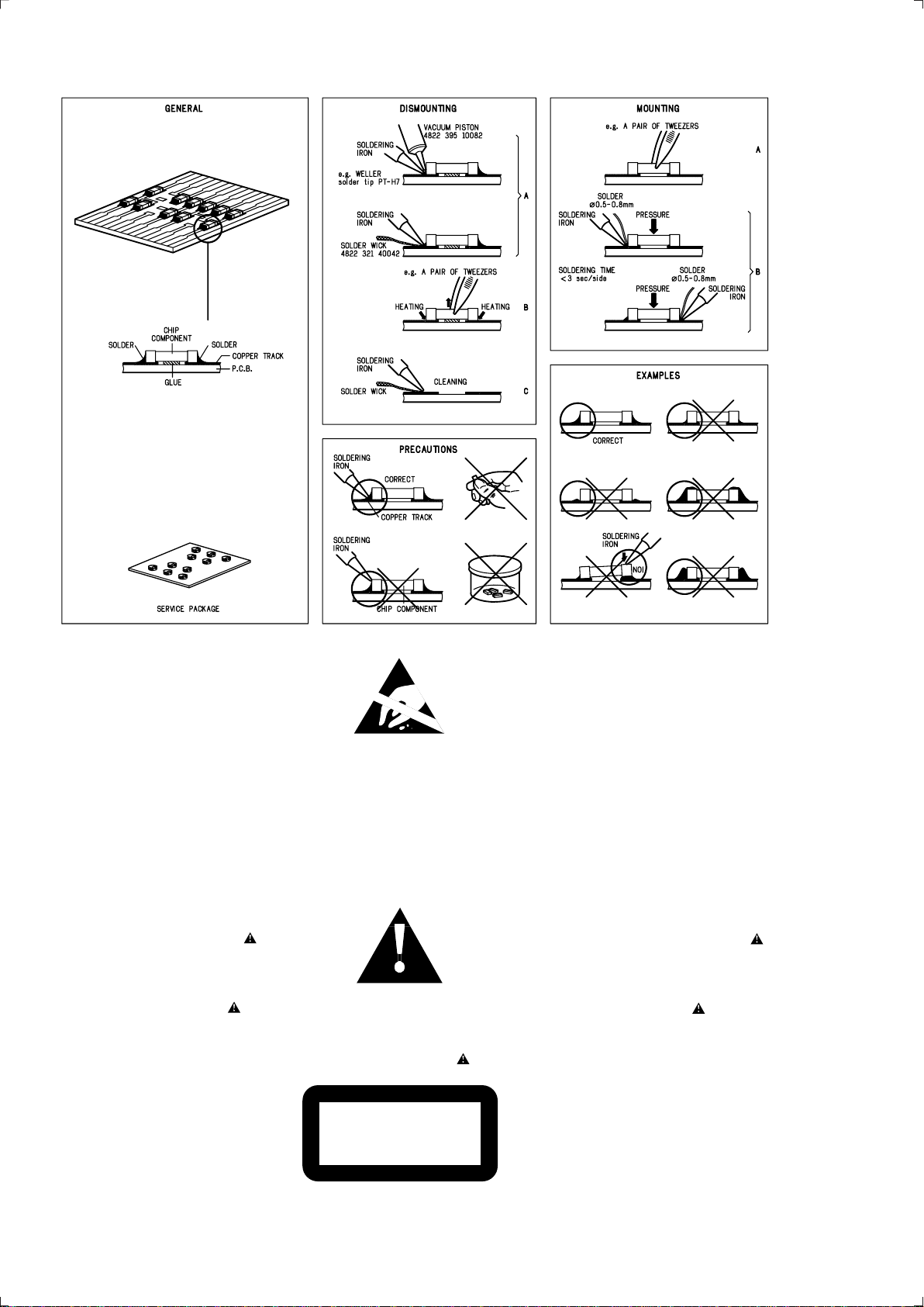
HANDLING CHIP COMPONENTS
1-1
© WARNING
All ICs and many other semiconductors are susceptible to
electrostatic discharges (ESD). Careless handling during
repair can reduce life drastically.
When repairing, make sure that you are connected with the
same potential as the mass of the set via a wristband with
resistance. Keep components and tools at this potential.
f ATTENTION
Tous les IC et beaucoup d ´autres semi-conducteurs sont
sensibles aux d écharges statiques (ESD). Leur long évite
pourrait être consid érablement écourt ée par le fait qu ´aucune
précaution n ést prise à leur manipulation.
Lors de r éparations, s ´assurer de bien être reli é au m ême
potentiel que la masse de l ´appareil et enfileer le bracelet
serti d ´une r ésistance de s écurit é.
Veiller à ce que les composants ainsi que les outils que l ´on
utilise soient également à ce potentiel.
©
Safety regulations require that the set be restored to its
original condition and that parts which are identical with
those specified be used.
Safety components are marked by the symbol
f
Les normes de s écurit é exigent que l`appareil soit remis
à l`état d`origine et que soient utilis ées les pi èces de
rechange identiques à celles sp écifiées.
Les composants de s écurit é sont marqu és
d WARNUNG
Alle ICs und viele andere Halbleiter sind empfindlich
gegen über elektrostatischen Entladungen (ESD).
Unsorgf ältige Behandlung im Reparaturfall kann die
Lebensdauer drastisch reduzieren.
Sorgen Sie daf ür, daß Sie im Reparaturfall über ein Pulsarmband mit Widerstand mit dem Massepotential des
Gerätes verbunden sind.
Halten Sie Bauteile und Hilfsmittel ebenfalls auf diesem
Potential.
d
Bei jeder Reparatur sind die geltenden Sicherheitsvorschriften zu beachten. Der Originalzustand des Ger ätes
darf nicht ver ändert werden. F ür Reparaturen sind Originalersatzteile zu verwenden.
Sicherheitsbauteile sind durch das Symbol markiert.
ESD
SAFETY
ñ WAARSCHUWING
Alle IC ´s en vele andere halfgeleiders zijn gevoelig voor
electrostatische ontladingen (ESD).
Onzorgvuldig behandelen tijdens reparatie kan de levensduur
drastisch doen vermindern. Zorg ervoor dat u tijdens reparat ie
via een polsband met weerstand verbonden bent met hetzelfde
potentiaal als de massa van het apparaat.
Houd componenten en hulpmiddelen ook op ditzelfde potentiaal .
i AVVERTIMENTO
Tutti IC e parecchi semi-conduttori sono sensibili alle scar iche
statiche (ESD).
La loro longevit à potrebbe essere fortemente ridatta in caso di
non osservazione della pi ù grande cauzione alla loro
manipolazione. Durante le riparationi occorre quindi essere
collegato allo stesso potenziale che quello della massa
delápparecchio tramite un braccialetto a resistenza.
Assicurarsi che i componenti e anche gli utensili con quali si
lavora siano anche a questo potenziale.
ñ
Veiligheidsbepalingen vereisen, dat het apparaat in zijn
oorspronkeliijke toestand wordt teruggebracht en dat
onderdelen, identiek aan de gespecificeerde, worden toegepas t.
De Veiligheidsonderdelen zijn aangeduid met het symbool
i
Le norme di sicurezza estigono che l ´apparecchio venga
rimesso nelle condizioni originali e che siano utilizzati i
pezzi di ricambiago identici a quelli specificati.
Componenty di sicurezza sono marcati con
©
DANGER : Invisible laser radiation when open.
AVOID DIRECT EXPOSURE TO BEAM.
s Varning !
Osynlig laserstr ålning n är apparaten är öppnad och
spärren är urkopplad. Betrakta ej str ålen.
∂ Advarsel !
Usynlig laserstr åling ved åbning n år sikkerhedsafbrydere
er ude af funktion. Undg å udsaettelse for str åling.
PCS 104 437
CLASS 1
LASER PRODUCT
ß Varoitus !
Avatussa laitteessa ja suojalukituksen ohitettaessa olet alt tiina
näkymättömälle laseris äteilylle. Älä katso s äteeseen !
©
After servicing and before returning the set to customer
perform a leakage current measurement test from all
exposed metal parts to earth ground, to assure no
shock hazard exists.
The leakage current must not exceed 0.5mA.
f
"Pour votre s écurite, ces documents doivent être utilis és par
des sp écialistes agr éés, seuls habilit és à réparer votre
appareil en panne".

TECHNICAL SPECIFICATIONS
2-1
GENERAL
Mains voltage -/00/14 : 230 V
-/01/11/16 : 120/230 V
-/05/10 : 240 V
-/17 : 120 V
Mains frequency -/00/05/10/14 : 50 Hz
-/01/11/16 : 50 / 60 Hz
-/17 : 60 Hz
Battery mains : 12 V (R20 x 8)
remote : 3 V (R03 x 2)
Power consumption max : < 35 W
standby : 2.3 W
Dimension (W x H x D) : 540 x 177 x 276 mm
Weight : 5.5 kg
AMPLIFIER
Output power mains : 2 x 6 W
battery : 2 x 6 W
Speaker impedance : 2 x 8 Ohm
x
:2
6 Ohm
Frequency response : 70 Hz - 10 kHz (-3dB)
TUNER - FM SECTION
TUNER - AM SECTION
Tuning range MW : 531 - 1602 kHz
-/17 : 530 - 1700 kHz
LW : 153 - 279 kHz
IF frequency : 468 kHz ± 3 kHz
Sensitivity MW : 1500 µV/m at 26dB S/N
LW : 5500 µV/m at 26dB S/N
Selectivity MW : 20 dB
LW : 29 dB
IF rejection ratio MW : 60 dB
LW : 60 dB
Image rejection ratio MW : 32 dB
LW : 38 dB
AUDIO CASSETTE RECORDER
Number of tracks : 1 stereo
Tape speed : 4.76 cm/sec ± 3%
Wow & flutter : < 0.48 % JIS UWTD
Fast wind/rewind C60 : < 110 sec.
Frequency response P/B : 125 - 8000 Hz
S/N ratio : > 38 dB
COMPACT DISC
Tuning range : 87.5 - 108 MHz
-/14 : 65.81 - 74 MHz
IF frequency : 10.7 MHz ± 0.2 MHz
Sensitivity : 14 dB at 26dB S/N
Selectivity : 55 dB at ±300kHz
IF rejection : 65 dB
Image rejection : 26 dB
Frequency response : 100 Hz - 10 kHz
S/N ratio : 60 dB
Channel difference 1 kHz : 2 dB
Channel crosstalk 1 kHz : 40 dB
Laser wavelength : 780 ± 20nm
Laser light power : < 0.3 mW
SERVICE TOOLS
Audio signal disc SBC 429.......................................................................4822 397 30184
Playability test disc SBC 444
Test disc 5 (disc without errors ) +
Test disc 5A (disc with dropout errors, black spots and fingerprints)
SBC 426/426A.....................................................................4822 397 30096
Burn in test disc (65 min. 1kHz signal at -30 dB level without “pause”)
Universal test cassette Fe SBC 420........................................................4822 397 30071
...................................................................4822 397 30245
.....4822 397 30155
AVAILABLE ESD PROTECTION EQUIPMENT
anti-static table mat large 1200x650x1.25mm 4822 466 10953
small 600x650x1.25mm 4822 466 10958
anti-static wristband 4822 395 10223
connection box (3 press stud connections, 1MΩ) 4822 320 11307
extendible cable (2m, 2MΩ, to connect wristband to connection box) 4822 320 11305
connecting cable (3m, 2MΩ, to connect table mat to connection box) 4822 320 11306
earth cable (1MΩ, to connect any product to mat or to connection box) 4822 320 11308
KIT ESD3 (combining all 6 prior products - small table mat) 4822 310 10671
wristband tester 4822 344 13999
PCS 107 272
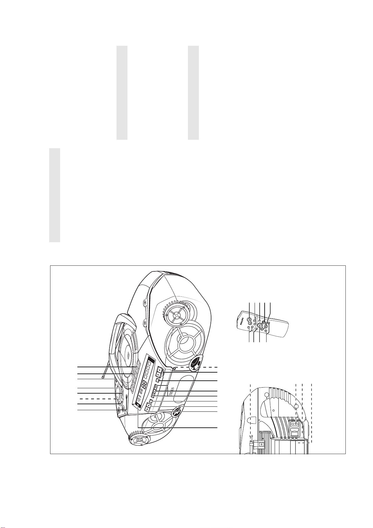
CONNECTIONS AND CONTROLS
for AZ2035 model only:
infrared sensor for
station (down, up)
programme;
CD: programmes tracks and reviews the
Tuner: programmes preset radio stations
$ PROG -
% BAND - selects waveband
^ PRESET 4, 3 - selects a preset tuner
& REMOTE SENSOR -
the loudspeakers.
selects a more vivid bass response
TOP AND FRONT PANELS
Note: Connecting headphones will switch off
1 p - 3.5 mm stereo headphone socket
2 ULTRABASS-
adjusts the treble tones
3 ULTRA HIGH CLARITY -
remote control
creates a super-enhanced stereo effect
4 INCREDIBLE SURROUND -
FM reception
BACK PANEL
* Telescopic aerial - improves
CD/ TUNER / TAPE and also
5 VOLUME - to adjust volume level
6 POWER slider - selects the sound source for
some versions only) before plugging in the
( AC MAINS - inlet for mains lead
) Voltage selector - (on the back of the set,
the POWER OFF switch
7 OPEN•CLOSE - opens/ closes the CD door
8 CASSETTE RECORDER keys
3-1
radio station
(for AZ2035 only)
– adjusts volume level
-
,
+
set, adjust selector to match the local
voltage
type R-20, UM-1 or D-cells
¡ Battery compartment - for eight batteries,
tape
- fast winds/rewinds the
/ 6
SEARCH 5
RECORD 0 - starts recording
PLAY 1 - starts playback
STOP•OPEN 9/ - stops the tape;
VOLUME
PRESET 3,4 (up, down) – selects a preset
2
TUNING ∞, § (down, up) – tunes to radio
3
REMOTE CONTROL
1
- opens the cassette door
is running low
CD playback
PAUSE ; - pauses recording or playback
9 BATT LOW - indicates when battery power
0 PLAY 2; - starts or pauses
stations
entire CD
track/ previous/ later track
interrupts CD playback
SHUFFLE – to play CD tracks in random order
REPEAT – repeats a track/ CD programme/
2; – starts and pauses CD playback/
¡, ™ – skips to the beginning of a current
STOP 9 – stops CD playback or erases a
4
5
6
7
8
erases a CD programme
! STOP 9 - stops CD playback;
/ §
track;
- skips to the beginning of a current
REPEAT or SHUFFLE (random) order
Tuner: - (down, up) tunes to radio stations;
CD: - searches back and forward within a
@ CD MODE - selects different play modes:
# SEARCH ∞
forwards within a track/CD
CD programme
SEARCH 5, 6 – searches backwards or
9
track/ previous/ later track
CAUTION
Use of controls or adjustments or performance of procedures other than herein
may result in hazardous radiation exposure.
23 54 61 7 8
18573
T
A
PE
RE
TUNING
UME
VOL
ET
ES
PR
R
E
M
E
T
N
S
Y
U
S
R
T
E
K
L
A
E
A
P
S
X
IT
LE
G
F
E
I
R
D
S
S
A
B
FM
STEREO
PRESET
BAND
SEARCH • • •
PROG
• • • SEARCH
CD MODE
BATT
LOW
STOP
Y
PLA
&
^#!0 @9 %$
2
*
CH
AR
SE
ontrol
C
STOP
E
emote
R
SHUFFL
RCH
SEA
igital
D
694
For AZ2035 model only
(¡)
PCS 107 273
INSTRUCTION FOR USE
SEARCH
PROG
BA
∑
3-2
SEARCH ¥ ¥ ¥
PROG
¥ ¥ ¥ SEARCH
TT
BA
LOW
CD MODE
STOP
Y
PLA
LOW
BATT
for AZ2035 model
PRESET 4, 3 keys on the set light up
CD, TUNER or TAPE.
Switching on and off
™ During playback, the PLAY 2;, STOP 9 and
• Adjust the POWER slider to the desired sound source:
™ The volume, tone, sound settings and tuner presets will be
• The set is switched off when the POWER slider is in the
PHILIPS demo mode
8 x R20 ¥ UM-1 ¥ D-CELLS
mode.
On the set, press the CD STOP 9 key for 5 seconds.
1.
To return to the current display you can either:
™ PH..IL ..IPS scrolls across the display continuously in the demo
2.
retained in the set's memory.
TAPE/OFF position and the keys on the tape deck are released.
or press VOLUME + or - on the remote control).
clockwise to decrease volume on the set (
demo mode for 30 seconds;
• press any function key on the front panel. This interrupts the
across the display once before the demo mode is cancelled.
• press the CD STOP 9 key for 5 seconds. PH..IL ..IPS scrolls
Adjusting volume and sound
only:
Turn the VOLUME control clockwise to increase or anti-
1.
Press ULTRABASS once or more to switch on or off.
and indicator 2 lights up.3.To adjust the treble tone level, press ULTRA HIGH CLARITY
once or more to switch on or off.
2.
™ If on, indicator 1 lights up. Press again if you want extra bass
™ Display shows the volume level VOL and a number from 0-32.
Press INCREDIBLE SURROUND once or more to switch the
4.
™ If on, the indicator lights up.
surround sound effect on or off.
e.g. alkaline with carbon zinc.
different types of music.
Note: The effect of INCREDIBLE SURROUND may vary with
™ If on, the indicator lights up.
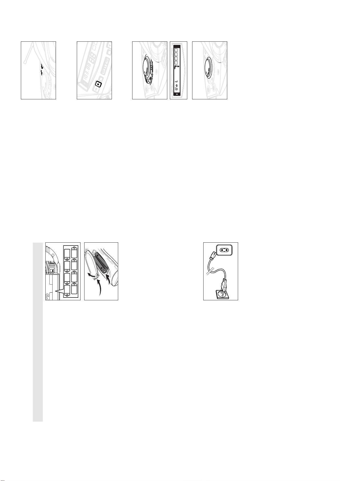
MAINS ~
Open the battery compartment and insert 8 batteries,
type R-20, UM-1 or D-cells, (preferably alkaline) with the
correct polarity as indicated by the "+" and "–" symbols inside
Whenever convenient, use the power supply if you want to
PCS 107 274
BATTERIES (not included)
conserve battery life. Make sure you remove the mains plug from
the set and wall socket before inserting batteries.
1.
the holder.
Remote control (for AZ2035 model only)
Replace the compartment door, making sure the batteries are
firmly and correctly in place. The set is now ready to operate.
2.
Open the battery compartment and insert two batteries,
type AAA, R03 or UM4 (preferably alkaline).
batteries are too weak.
– The BATT LOW indicator eventually goes out if the
If BATT LOW lights up, battery power is running low.
–
corrode the compartment or cause the batteries to burst.
Incorrect use of batteries can cause electrolyte leakage and will
Only use batteries of the same type for the set.
Do not mix battery types:
Therefore:
•
• When inserting new batteries, do not try to mix old batteries
with the new ones.
time.
be disposed of properly.
Batteries contain chemical substances, so they should
• Remove the batteries if the set is not to be used for a long
•
Check if the mains supply, as shown on the type plate
located on the bottom of the set, corresponds to your local
mains supply. If it does not, consult your dealer or service
centre.2.If your set is equipped with a voltage selector, adjust the
Using AC POWER
1.
selector so that it matches with the local mains supply.3.Connect the mains lead to the wall socket and the set is now
ready for use.
To disconnect the set from the mains supply completely,
remove the mains plug from the wall socket.
4.
FM
STEREO
INSTRUCTION FOR USE
∑
3-3
or on the
for AZ2035 model only:
frequency, waveband and, if programmed, a preset number is
Select TUNER source.
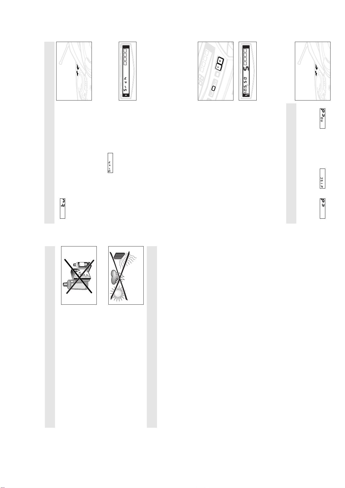
TUNING TO RADIO STATIONS
1.
shown.
Press BAND once or more to select your waveband.
Press SEARCH ∞ or § (
remote control TUNING ∞ or §) and release when the
frequency in the display starts running.
™ is displayed briefly and then the radio station
2.
3.
reception. Display shows during automatic tuning.
™ The tuner automatically tunes to a station of sufficient
AM
LOW
BATT
is shown.
STEREO
, the set is provided with a built-in aerial so the
, pull out the telescopic aerial. Incline and turn the aerial.
FM
Repeat step 3 if necessary until you find the desired station.
repeatedly until you have found optimal reception.
4.
• To tune to a weak station, press SEARCH ∞ or § briefly and
™ If an FM station is received in stereo,
To improve radio reception
– For
MW (AM)
Reduce its length if the signal is too strong (very close to a
transmitter).
telescopic aerial is not needed. Direct the aerial by turning the
whole set.
– For
FM
STEREO
PRESET
AND
B
¥
¥
SEARCH ¥
PROG
SEARCH
¥
¥
¥
flashes.
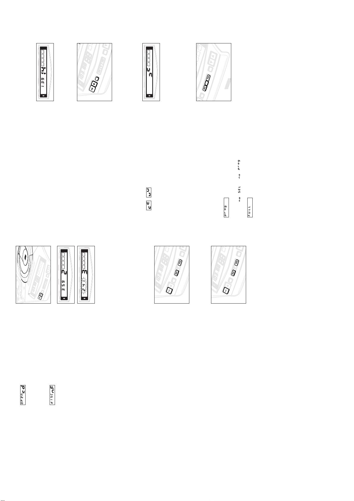
PROGRAM
Tune to your desired station (see Tuning to radio stations).2.Press PROG to activate programming.
Programming radio stations
You can store up to a total of 30 radio stations in the memory.
1.
Press PRESET 4 or 3 once or more to allocate a number from
1 to 30 to this station.
– Display:
3.
FM
STEREO
PROGRAM
LOW
BATT
disappears, the preset number and the
PROGRAM
Press PROG again to confirm the setting.
frequency of the preset station are shown.
– Display:
4.
41
Repeat the above four steps to store other stations.
in its place.
• You can overwrite a preset station by storing another frequency
5.
Tuning to preset stations
PLAYING A CD
Press PRESET 4 or 3 until the desired preset station is
displayed.
This CD player plays Audio Discs including CD-Recordables and
Select CD source.
™ and are displayed briefly, if
1.
CD-Rewritables.
(some versions only)
press simultaneously, PROG and BAND.
press simultaneously, PROG and SEARCH §.
rain, sand or excessive heat caused by heating equipment or
direct sunlight.
Do not use any cleaning agents containing alcohol, ammonia,
GENERAL INFORMATION
General maintenance
• Do not expose the set, batteries, CDs or cassettes to humidity,
benzene or abrasives as these may harm the housing.
• To clean the set, use a soft, slightly dampened chamois leather.
not tilt. Make sure there is adequate ventilation to prevent the
system from overheating.
and must not be oiled or lubricated.
TUNING
Safety information
• Place the set on a hard and flat surface so that the system does
• The mechanical parts of the set contain self-lubricating bearings
Changing tuning grid
respectively. In the rest of the world this step is 9 KHz and
50 KHz. Usually the frequency step has been preset in the factory
In North and South America the frequency step between adjacent
channels in the AM and FM band are 10 KHz and 100 KHz
for your area.
Release the controls only when you switch on the set.
Check that the set is in the TAPE/OFF position and switched off.
1.
To select 10KHz:
Release the controls only when you switch on the set.
•
2. To select 9KHz:
either steps of 9 or 10.
™ When tuning to radio stations, the display shows tuning in
reprogramme your presets.
™ All preset stations will be affected and you may need to
PCS 107 275
SEARCH
PRESET
SEARCH
PRESE
TT
INSTRUCTION FOR USE
BA
TT
LOW
DIGIT
AL
TUN
ER
A
S
S
R
E
F
LE
X
S
P
E
A
K
E
R
S
Y
S
T
E
M
ST
OP
PRES
ST
OP
PRES
∑
3-4
PRE
BAND
REPEAT ALL
SHUFFLE
LOW
BATT
TT
BA
LOW
SEARCH ¥ ¥ ¥
PROG
¥ ¥ ¥ SEARCH
CD MODE
STOP
Y
PLA
for AZ2035
continuously in random order
- to repeat the entire CD/ programme
REPEAT ALL
- to repeat the entire CD/ programme
random order
- tracks of the entire CD/ programme are played in
and
Different play modes: SHUFFLE and REPEAT
You can select and change the various play modes before or during
playback. The play modes can also be combined with PROG.
SHUFFLE
SHUFFLE
REPEAT ALL
or on the remote control SHUFFLE or
or on the remote control the respective SHUFFLE or
- to play the current track continuously
for AZ2035 model only:
To select your play mode, press CD MODE
(
REPEAT
1.
REPEAT) before or during playback until the display shows the
desired function.
REPEAT key) until the various SHUFFLE/ REPEAT modes are no
Press PLAY 2; to start playback if in the STOP position.
To return to normal playback, press CD MODE (
model only:
2.
3.
FM
STEREO
SHUFFLE
LOW
BATT
CD MODE
for AZ2035 model only:
) to select your desired track
to cancel your play mode.
¡ or ™
STOP 9
, when the CD player selects a random track
number.
longer displayed.
– You can also press
Note: In SHUFFLE mode, the display shows rapid patterns e.g.
Programming track numbers
In the STOP position, select and store your CD tracks in the desired
Use the SEARCH ∞ or § on the set, (
or on the remote control
sequence. If you like, store any track more than once.
Up to 20 tracks can be stored in the memory.
1.
PRESET
AND
B
¥
¥
¥
SEARCH
PROG
SEARCH
¥
¥
¥
or on the remote control 2;).
and the selected track number.
appears briefly.
PROGRAM
number.
Press PROG.
2.
™ Display:
Repeat steps 1-2 to select and store all desired tracks.
number, or scrolls across the display.
3.
™ If you attempt to programme without first selecting a track
for AZ2035 model only:
20 tracks.4.To start playback of your CD program, press PLAY 2;
(
™ is displayed if you attempt to programme more than
R
E
M
E
N
T
S
Y
U
S
T
R
E
K
L
A
E
A
P
S
T
I
X
E
L
G
F
I
E
R
D
S
S
A
B
FM
STEREO
BAND
SEARCH ¥ ¥ ¥
PROG
¥ ¥ ¥ SEARCH
CD MODE
TT
BA
LOW
STOP
PLAY
LOW
BATT
LOW
BATT
for AZ2035 model only:
Press OPEN•CLOSE to open the CD compartment.
Insert a CD with the printed side facing up and press
OPEN•CLOSE to close the CD compartment.
total number of tracks and playing time are shown.
Display: is shown if you have inserted a
non-finalized CD-R(W).
Press PLAY 2; (
or on the remote control 2;) to start playback.
track during CD playback.
™ Display: when you open the CD compartment.
2.
™ Display: the CD player scans the contents of a CD, and then the
3.
4.
To pause playback press PLAY 2;.
™ Display: Current track number and elapsed playing time of the
5.
PRE
BAND
SEARCH ¥ ¥ ¥
PROG
¥ ¥ ¥ SEARCH
CD MODE
TT
BA
LOW
OP
ST
PLAY
.
TUNER
or
for AZ2035 model only:
TAPE
or on the remote control 2;) to start
– you select another source:
– the CD has reached the end
– the CD door is opened;
To stop CD playback, press STOP 9.
Press PLAY 2; again to resume play.
pause.
6.
™ Display: the elapsed playing time flashes when playback is on
Note: CD play will also stop when:
or on the remote control ¡ or ™) once or repeatedly until the
Selecting a different track
desired track number appears in the display.
• Press SEARCH ∞ or § on the set, (
for AZ2035 model only:
in the PAUSE position, you will need to press PLAY 2;
(
• If you have selected a track number shortly after loading a CD or
playback.
PRE
BAND
SEARCH ¥ ¥ ¥
PROG
¥ ¥ ¥ SEARCH
TT
BA
CD MODE
LOW
OP
ST
PLAY
or on the remote control 5 or 6).
searching is only possible within a track.
for AZ2035 model only:
Press and hold down SEARCH ∞ or §
(
When you recognize the passage you want, release
SEARCH ∞ or §.
Finding a passage within a track
™ The CD is played at high speed and low volume.
1.
2.
Note: During a CD programme or if SHUFFLE/ REPEAT is active,
– Normal playback continues.
PCS 107 276
INSTRUCTION FOR USE
SEARCH
B
A
B
A
Altering the
3-5
FM
FM
STEREO
PROG
¥ ¥ ¥ SEARCH
DE
for AZ2035 model only:
It is not necessary to start the
or on the remote control ¡ or ™).
BAND
SEARCH ¥ ¥ ¥
VOLUME, INCREDIBLE SURROUND, ULTRABASS or ULTRA
HIGH CLARITY controls will not affect the recording in
progress.
place during the 7 seconds when the leader tape passes the
recorder heads.
of you and break out the left tab.
Recording on this side is no longer possible. If, however, you
third parties are not infringed.
GENERAL INFORMATION ON RECORDING
• Recording is permissible insofar as copyright or other rights of
The best recording level is set automatically.
METAL (IEC IV) type cassettes. For recording, use NORMAL type
cassettes (IEC I) on which the tabs have not yet been broken.
• This deck is not suitable for recording on CHROME (IEC II) or
•
BATT
LOW
• At the very beginning and end of the tape, no recording will take
PRES
BAND
SEARCH ¥ ¥ ¥
PROG
¥ ¥ ¥ SEARCH
CD MODE
STOP
Y
PLA
PROGRAM
wish to record over this side again, cover the tabs with a piece
• To protect a tape from accidental erasure, have the tape in front
X
of adhesive tape.
Select CD source.2.Insert a CD and if desired, programme track numbers.
SYNCHRO START CD RECORDING
1.
Press STOP•OPEN 9/ to open the cassette door.4.Insert a suitable cassette into the cassette deck and close the
cassette door.5.Press RECORD 0 to start recording.
3.
CD player separately.
beginning of the programme.
– Playing of the CD programme starts automatically from the
for AZ2035 model only:
(
To select and record a particular passage within a track
• Press and hold down SEARCH ∞ or §
• When you recognize the passage you want, release
or on the remote control 2;).
SEARCH ∞ or §.
• To pause CD playback press PLAY 2; (
For brief interruptions press PAUSE ;. To resume recording,
press RECORD 0.
– Recording will begin from this exact point in the track when you
press PAUSE ; again.7.To stop recording, press STOP•OPEN 9/.
6.
FM
has been activated.
PAUSE ;
again.
disappears.
Reviewing the programme
In the STOP position or during playback, press and hold down
PROG for a while until the display shows all your stored track
numbers in sequence.
Erasing a programme
You can erase the programme by:
– selecting another source: TAPE or TUNER.
– pressing STOP 9 twice in the STOP position or during playback.
• scrolls across the display briefly and
available cleaning CD to clean the lens before taking the set to
repair. Other cleaning methods may destroy the lens.
CD player and CD handling
• If the CD player cannot read CDs correctly, use a commonly
condensation to cloud over on the lens of your CD player. Playing
a CD is then not possible. Do not attempt to clean the lens but
leave the set in a warm environment until the moisture
evaporates.
lens.
the CD. Always pick up the CD by the edge and return the CD to
• The lens of the CD player should never be touched!
• Sudden changes in the surrounding temperature can cause
• Always keep the CD compartment closed to avoid dust on the
its box after use to avoid scratching and dust.
• To take a CD out of its box, press the centre spindle while lifting
• To clean the CD, wipe in a straight line from the centre towards
the edge using a soft, lint-free cloth. Do not use cleaning agents
as they may damage the disc.
• Never write on a CD or attach any stickers to it.
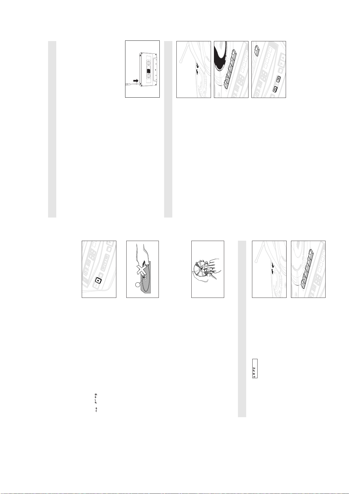
Select TAPE source.
CASSETTE PLAYBACK
Press STOP•OPEN 9/ to open the cassette door.3.Insert a recorded cassette and close the cassette door.4.Press PLAY 1 to start playback.
™ The display shows throughout tape operation.
1.
2.
To interrupt playback, press PAUSE ;. To resume, press this key
5.
tape is possible in both directions.
By pressing SEARCH 5 or 6 on the set, fast winding of the
To stop the tape, press STOP•OPEN 9/.
6.
except if
7.
– The keys are automatically released at the end of the tape,
PCS 107 277
INSTRUCTION FOR USE
BA
3-6
indication
CD-R(W) is blank or the disc is not finalised
CD badly scratched or dirty
• Use a finalised CD-R(W)
–
• Replace/ clean CD, see MAINTENANCE
The CD skips tracks
– CD is damaged or dirty
• Replace or clean the CD
– SHUFFLE or PROGRAM is active
• Switch off SHUFFLE/ PROGRAM
Poor cassette sound quality
–
invalidate the guarantee.
circumstances should you try to repair the set yourself, as this would
If a fault occurs, first check the points listed below before taking the set for repair.
If you are unable to remedy a problem by following these hints, consult your dealer or service centre.
WARNING: Do not open the set as there is a risk of electric shock. Under no
PROBLEM
– POSSIBLE CAUSE
• REMEDY
FM
No sound/power
– VOLUME not adjusted
• Adjust the VOLUME
– Headphones connected
• Disconnect headphones
– mains lead not securely connected
• Connect the AC mains lead properly
– Dust and dirt on the heads, etc.
– Batteries dead/ incorrectly inserted
• Insert (fresh) batteries correctly
A AB
CHROME).
• Clean deck parts etc., see MAINTENANCE
– Use of incompatible cassette types (METAL or
• Only use NORMAL (IEC I) for recording.
Recording does not work
– Cassette tab(s) may be broken
VCR or computer
Electrical interference: set too close to TV,
Severe radio hum or noise
–
• Increase the distance
Weak radio signal
Poor radio reception
–
missing tab space.
• Apply a piece of adhesive tape over the
Remote control does not function properly
– Batteries dead/ incorrectly inserted
• Insert (fresh) batteries correctly
– Distance/ angle between the set too large
etc.
• Reduce the distance/ angle
– Remote sensor obstructed by object, sticker
• Remove obstruction/ make sure right hand
indication
No CD inserted
CD badly scratched or dirty
optimum reception
• FM: Direct the FM telescopic aerial for
• Insert a CD
–
Laser lens steamed up
–
• Replace/ clean CD, see MAINTENANCE
–
• Wait until lens has cleared
side of cassette door is free from obstruction
The type plate is located on the bottom of the set.
C
cleaning cassette through once.
Tune to the desired radio station (See Tuning to radio sations).2.Press STOP•OPEN 9/ to open the cassette door. 3.Insert a suitable cassette into the cassette deck and close the
Recording from the radio
1.
press PAUSE ; again.
cassette door.4.Press RECORD 0 to start recording.
For brief interruptions, press PAUSE ;. To resume recording,
To stop recording, press STOP•OPEN 9/.
5.
6.
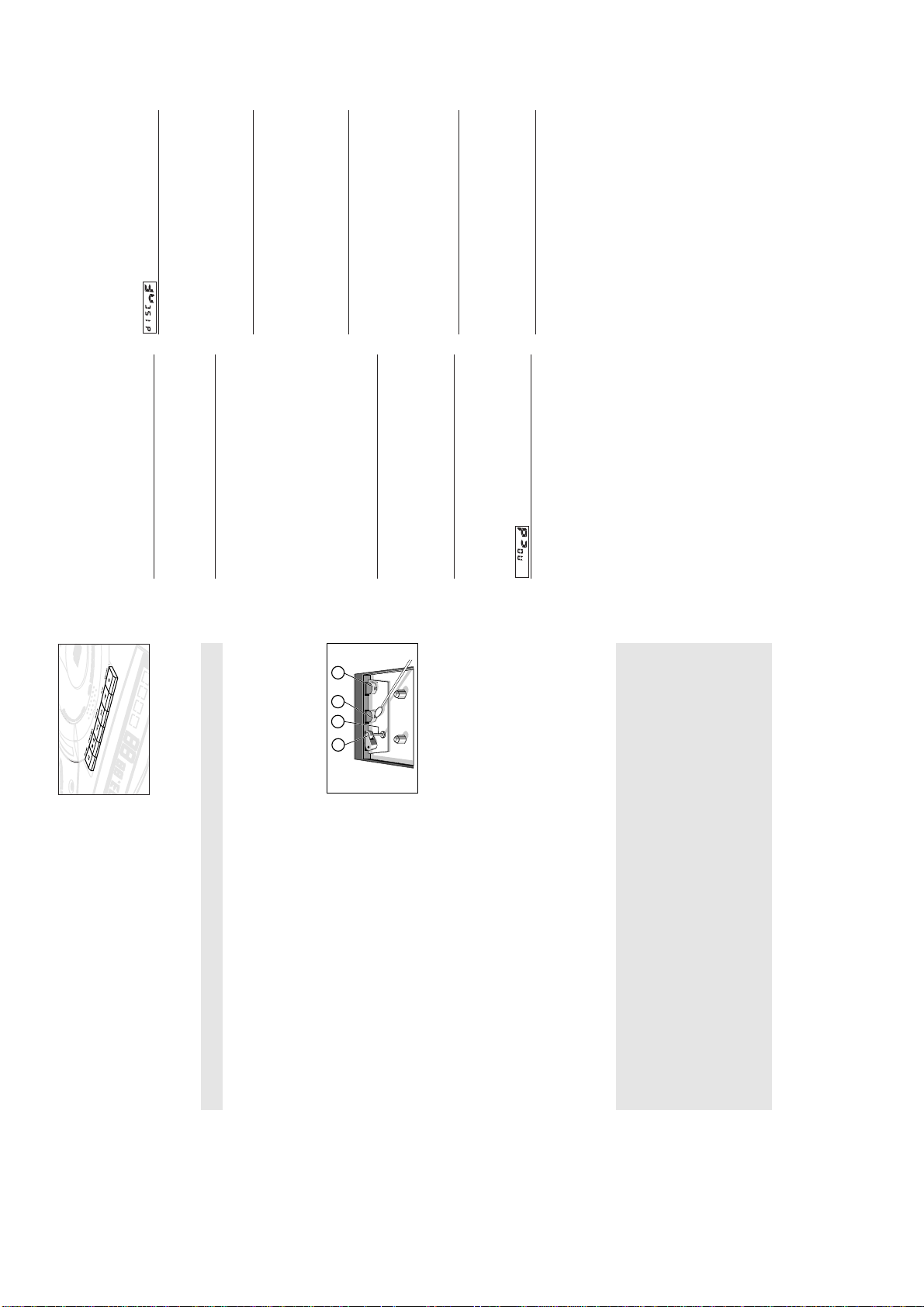
Open the cassette door by pressing STOP•OPEN 9/.2.Press PLAY 1 and clean the rubber pressure roller C. 3.Press PAUSE ; and clean the magnetic heads A and also the
MAINTENANCE
Tape deck maintenance
To ensure quality recording and playback of the tape deck, clean
parts A,B and C shown in the diagram below, after approx.
50 hours of operation, or on average once a month. Use a cotton
bud slightly moistened with alcohol or a special head cleaning fluid
to clean the deck.
capstan B .4.After cleaning, press STOP•OPEN 9/.
1.
Note: Cleaning of the heads can also be done by playing a
Environmental information
All unnecessary packaging material has been omitted. We have tried to make the packaging easy
to separate into three mono-materials: cardboard (box), expandable polystyrene (buffer),
polyethylene (bags, protective foam).
Your set consists of materials which can be recycled if disassembled by a specialized
company. Please observe the local regulations regarding the disposal of packing
materials, exhausted batteries and old equipment.
PCS 107 278

4-1 4-1
DISASSEMBLY DIAGRAM
A. To remove the Top Cabinet and Front Panel Assy
A7. Lift from the centre back (ventilation slot) to remove Top Cabinet (see fig. 1 & 2)
B. To separate Top Cabinet and Top Cabinet Bracket
C. To separate Front Panel Assy and Top Cabinet Bracket
D. To reomve Tape Deck
E. To remove Front Board
F. To remove Panel LCD Assy
G. To separate Front Cabinet and Rear Cabinet
·
fig.1
fig.2
PCS 107 279
 Loading...