

Philips AZ-1538 Service manual
CD Sound Machine
AZ 1538
all versions
Handling Chip Components and Safety ..........................1 - 1
Technical Specification & Service tools...........................2 - 1
Service Measurement......................................................2 - 2
Connections and controls.......................................3 - 1..3 - 2
Instructions for use.................................................3 - 3..3 - 4
Tuner adjustment.............................................................3 - 5
Abbreviations and Pin-description of CD ICs ..................4 - 1
Disassembly Diagram......................................................4 - 2
Block Diagram .................................................................5 - 1
Wiring Diagram................................................................5 - 2
Combi Board - Circuit Diagram
Front part.................................................................6 - 1
Tuner part................................................................7 - 1
Combi Board - Circuit Diagram
CD part 1 ................................................................8 - 1
CD part 2 ................................................................8 - 2
Audio/supply part.....................................................9 - 1
Combi Board - Layout Diagram
Layout diagram (copper side)................................10 - 1
Layout diagram (component side).........................10 - 2
MP3CD2002 Board
Circuit diagram......................................................11 - 1
Layout diagram......................................................11 - 2
Exploded view - cabinet.................................................12 - 1
Mechanical partslist.......................................................12 - 1
Electrical partslist .............................................13 - 1 .. 13 - 8
© 3140 785 32120
Published by LX 0227 Service Audio Printed in The Netherlands Subject to modification
CLASS 1
LASER PRODUCT
TABLE OF CONTENTS
©
Copyright 2001 Philips Consumer Electronics B.V. Eindhoven, The Netherlands
All rights reserved. No part of this publication may be reproduced, stored in a retrieval
system or transmitted, in any form or by any means, electronic, mechanical, photocopying,
or otherwise without the prior permission of Philips.
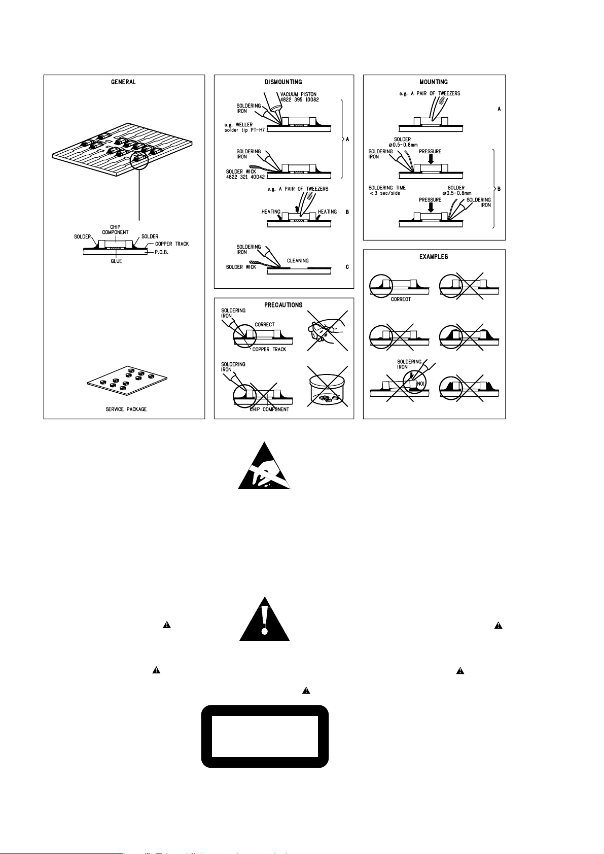
HANDLING CHIP COMPONENTS
© WARNING
All ICs and many other semiconductors are susceptible to
electrostatic discharges (ESD). Careless handling during
repair can reduce life drastically.
When repairing, make sure that you are connected with the
same potential as the mass of the set via a wristband with
resistance. Keep components and tools at this potential.
f ATTENTION
Tous les IC et beaucoup d´autres semi-conducteurs sont
sensibles aux décharges statiques (ESD). Leur longévite
pourrait être considérablement écourtée par le fait qu´aucune
précaution nést prise à leur manipulation.
Lors de réparations, s´assurer de bien être relié au même
potentiel que la masse de l´appareil et enfileer le bracelet
serti d´une résistance de sécurité.
Veiller à ce que les composants ainsi que les outils que l´on
utilise soient également à ce potentiel.
d WARNUNG
Alle ICs und viele andere Halbleiter sind empfindlich
gegenüber elektrostatischen Entladungen (ESD).
Unsorgfältige Behandlung im Reparaturfall kann die
Lebensdauer drastisch reduzieren.
Sorgen Sie dafür, daß Sie im Reparaturfall über ein Puls-
armband mit Widerstand mit dem Massepotential des
Gerätes verbunden sind.
Halten Sie Bauteile und Hilfsmittel ebenfalls auf diesem
Potential.
ñ WAARSCHUWING
Alle IC´s en vele andere halfgeleiders zijn gevoelig voor
electrostatische ontladingen (ESD).
Onzorgvuldig behandelen tijdens reparatie kan de levensduur
drastisch doen vermindern. Zorg ervoor dat u tijdens reparatie
via een polsband met weerstand verbonden bent met hetzelfde
potentiaal als de massa van het apparaat.
Houd componenten en hulpmiddelen ook op ditzelfde potentiaal.
i AVVERTIMENTO
Tutti IC e parecchi semi-conduttori sono sensibili alle scariche
statiche (ESD).
La loro longevità potrebbe essere fortemente ridatta in caso di
non osservazione della più grande cauzione alla loro
manipolazione. Durante le riparationi occorre quindi essere
collegato allo stesso potenziale che quello della massa
delápparecchio tramite un braccialetto a resistenza.
Assicurarsi che i componenti e anche gli utensili con quali si
lavora siano anche a questo potenziale.
©
Safety regulations require that the set be restored to its
original condition and that parts which are identical with
those specified be used.
Safety components are marked by the symbol
i
Le norme di sicurezza estigono che l´apparecchio venga
rimesso nelle condizioni originali e che siano utilizzati i
pezzi di ricambiago identici a quelli specificati.
Componenty di sicurezza sono marcati con
ñ
Veiligheidsbepalingen vereisen, dat het apparaat in zijn
oorspronkeliijke toestand wordt teruggebracht en dat
onderdelen, identiek aan de gespecificeerde, worden toegepast.
De Veiligheidsonderdelen zijn aangeduid met het symbool
s Varning !
Osynlig laserstrålning när apparaten är öppnad och
spärren är urkopplad. Betrakta ej strålen.
∂ Advarsel !
Usynlig laserstråling ved åbning når sikkerhedsafbrydere
er ude af funktion. Undgå udsaettelse for stråling.
ß Varoitus !
Avatussa laitteessa ja suojalukituksen ohitettaessa olet alttiina
näkymättömälle laserisäteilylle. Älä katso säteeseen !
f
"Pour votre sécurite, ces documents doivent être utilisés par
des spécialistes agréés, seuls habilités à réparer votre
appareil en panne".
ESD
SAFETY
d
Bei jeder Reparatur sind die geltenden Sicherheitsvorschriften zu beachten. Der Originalzustand des Gerätes
darf nicht verändert werden. Für Reparaturen sind Original-
ersatzteile zu verwenden.
Sicherheitsbauteile sind durch das Symbol markiert.
f
Les normes de sécurité exigent que l`appareil soit remis
à l`état d`origine et que soient utilisées les pièces de
rechange identiques à celles spécifiées.
Les composants de sécurité sont marqués
CLASS 1
LASER PRODUCT
©
DANGER: Invisible laser radiation when open.
©
After servicing and before returning the set to customer
perform a leakage current measurement test from all
exposed metal parts to earth ground, to assure no
shock hazard exists.
The leakage current must not exceed 0.5mA.
AVOID DIRECT EXPOSURE TO BEAM.
1 - 1

GENERAL
Mains voltage -/00C : 230 V
-/01 : 120 / 230 V
Mains frequency -/00C : 50 Hz
-/01 : 50 / 60 Hz
Battery main set : 9 V (R14 x 6)
remote : 3V (R6 x 2)
Power consumption : < 30 W (max.)
Dimension (W x H x D) : 405 x 162 x 232 mm
Weight : 2.5 Kg
AMPLIFIER
Output power mains : 2 x 1 W
battery : 2 x 0.8 W
Speaker impedance : 2 x 8 oh m
Frequency response : 60 Hz - 2 0 kHz (±3dB)
TUNER - FM SECTION
Tuning range : 87.5 - 108 MHz
IF frequency : 10.7 MHz ± 0.02 MHz
Sensitivity : 20 dBf at 26dB S/N
Selectivity : 24 dB at 300kHz
IF rejection : 85 dB
Image rejection : 24 dB
SPECIFICATIONS
TUNER - AM SECTION
Tuning range MW : 531 - 1602 kHz
LW : 153 - 279 kHz
IF frequency : 450 kHz ± 1 kHz
Sensitivity MW : 3200 µV/m at 26dB S/N
LW : 5500 µV/m at 26dB S/N
Selectivity MW : 22 dB
LW : 29 dB
IF rejection MW : 64 dB
LW : 60 dB
Image rejection MW : 32 dB
LW : 38 dB
COMPACT DISC
Frequency response : 100 Hz - 10 kHz ± 2dB
S/N ratio : 60 dB
Channel difference 1 kHz : 2 dB
Channel crosstalk 1 kHz : 40 dB
Laser wavelength : 780 ± 20 nm
Laser light power : < 0.5 mW
2 - 1
SERVICE TOOLS
Audio signal disc SBC 429.......................................................................4822 397 30184
Playability test disc SBC 444
...................................................................4822 397 30245
Test disc 5 (disc without errors ) +
Test disc 5A (disc with dropout errors, black spots and fingerprints)
SBC 426/426A.....................................................................4822 397 30096
Burn in test disc (65 min. 1kHz signal at -30 dB level without “pause”)
.....4822 397 30155
anti-static table mat
large 1200x650x1.25mm 4822 466 10953
small 600x650x1.25m 4822 466 10958
anti-static wristband
4822 395 10223
connection box (3 press stud connections, 1MΩ) 4822 320 11307
extendible cable (2m, 2MΩ, to connect wristband to connection box) 4822 320 11305
connecting cable (3m, 2MΩ, to connect table mat to connection box) 4822 320 11306
earth cable (1MΩ, to connect any product to mat or to connection box) 4822 320 11308
KIT ESD3 (combining all 6 prior products - small table mat) 4822 310 10671
wristband tester 4822 344 13999
AVAILABLE ESD PROTECTION EQUIPMENT
TECHNICAL SPECIFICATIONS
2 - 2
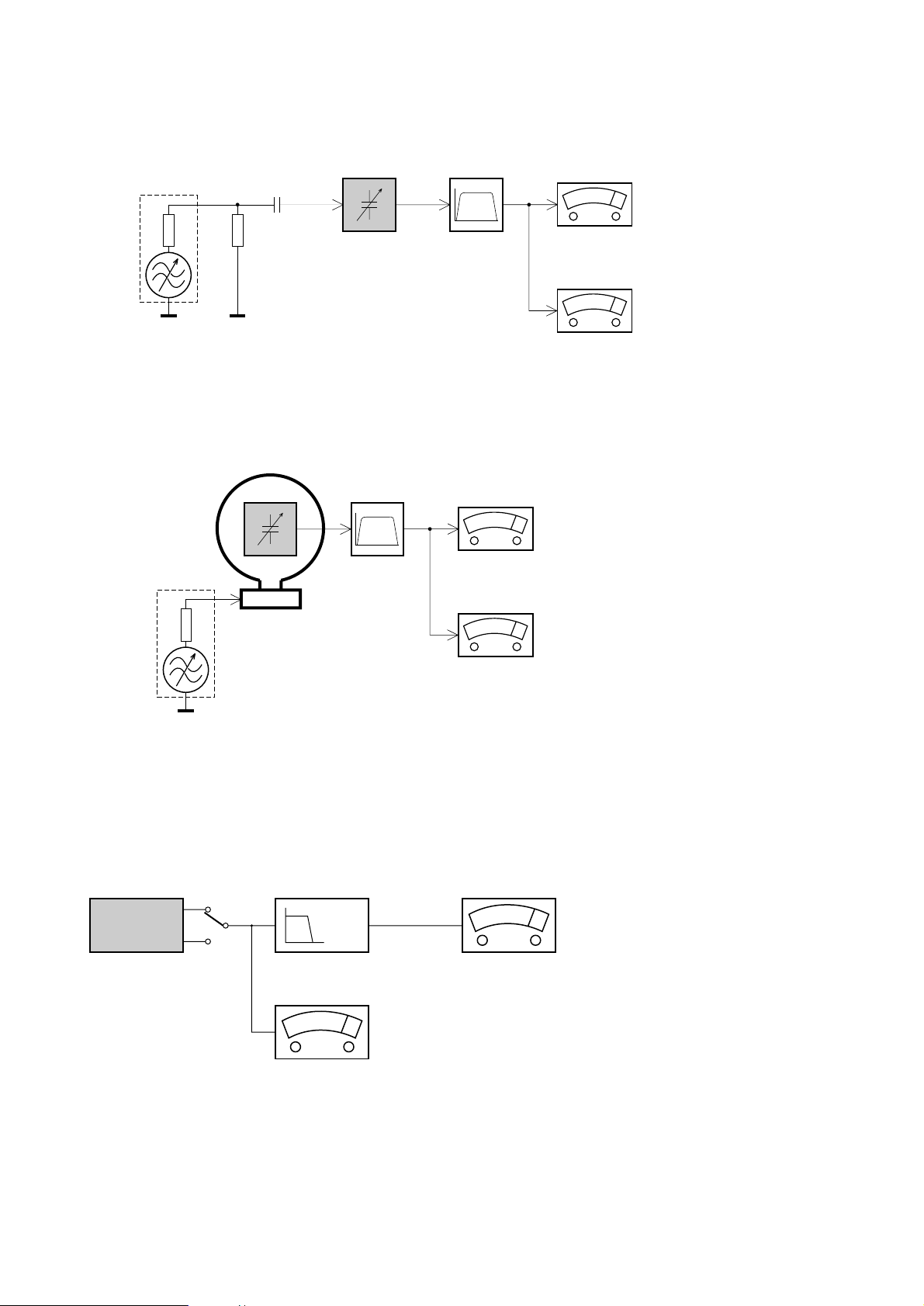
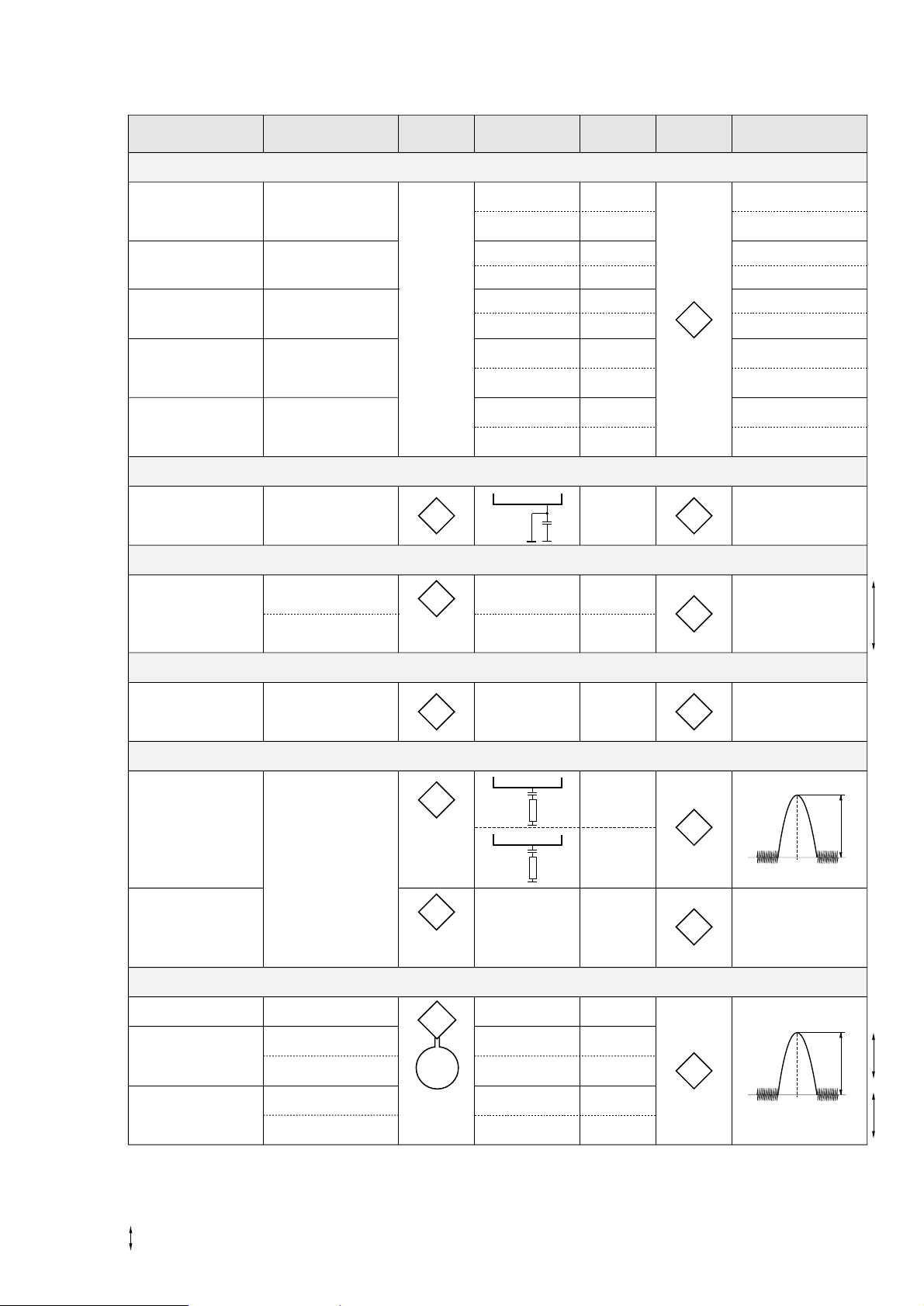
SERVICE MEASUREMENT
Bandpass
250Hz-15kHz
e.g. 7122 707 48001
LF Voltmeter
e.g. PM2534
DUT
RF Generator
e.g. PM5326
S/N and distortion meter
e.g. Sound Technology ST1700B
Tuner SW
To avoid atmospheric interference all AM-measurements have to be carried out in a Faraday«s cage.
Use a bandpass filter (or at least a high pass filter with 250Hz) to eliminate hum (50Hz, 100Hz).
Ri=50Ω
Aerial replacement
Capacitor
R=50Ω
Bandpass
250Hz-15kHz
e.g. 7122 707 48001
LF Voltmeter
e.g. PM2534
DUT
S/N and distortion meter
e.g. Sound Technology ST1700B
Frame aerial
e.g. 7122 707 89001
Tuner AM (MW,LW)
To avoid atmospheric interference all AM-measurements have to be carried out in a Faraday«s cage.
RF Generator
e.g. PM5326
Ri=50Ω
Low pass filter 22kHz
L
R
LEVEL METER
e.g. Sennheiser UPM550
with FF-filter
S/N and distortion meter
e.g. Sound Technology ST1700B
DUT
CD
Use Audio Signal Disc SBC429 4822 397 30184 (replaces test disc 3)
L.P.F. = 13
th
order filter 4822 395 30204
3 - 1
CONNECTIONS AND CONTROLS
VOLUME
SEARCH
PRESET
TUNING
REPEAT
SHUFFLE
SEARCH
+
-
*
$
%
^
&
9564321 87
0# !@
1
9
867
2
435
X
PROGRAM
DB
FM
DB
DB
CK
DB
CK
TRA
MP3
ALBUM
TRA

3 - 2
ACCESSORIES
1 x AC mains lead
1 x Remote Control
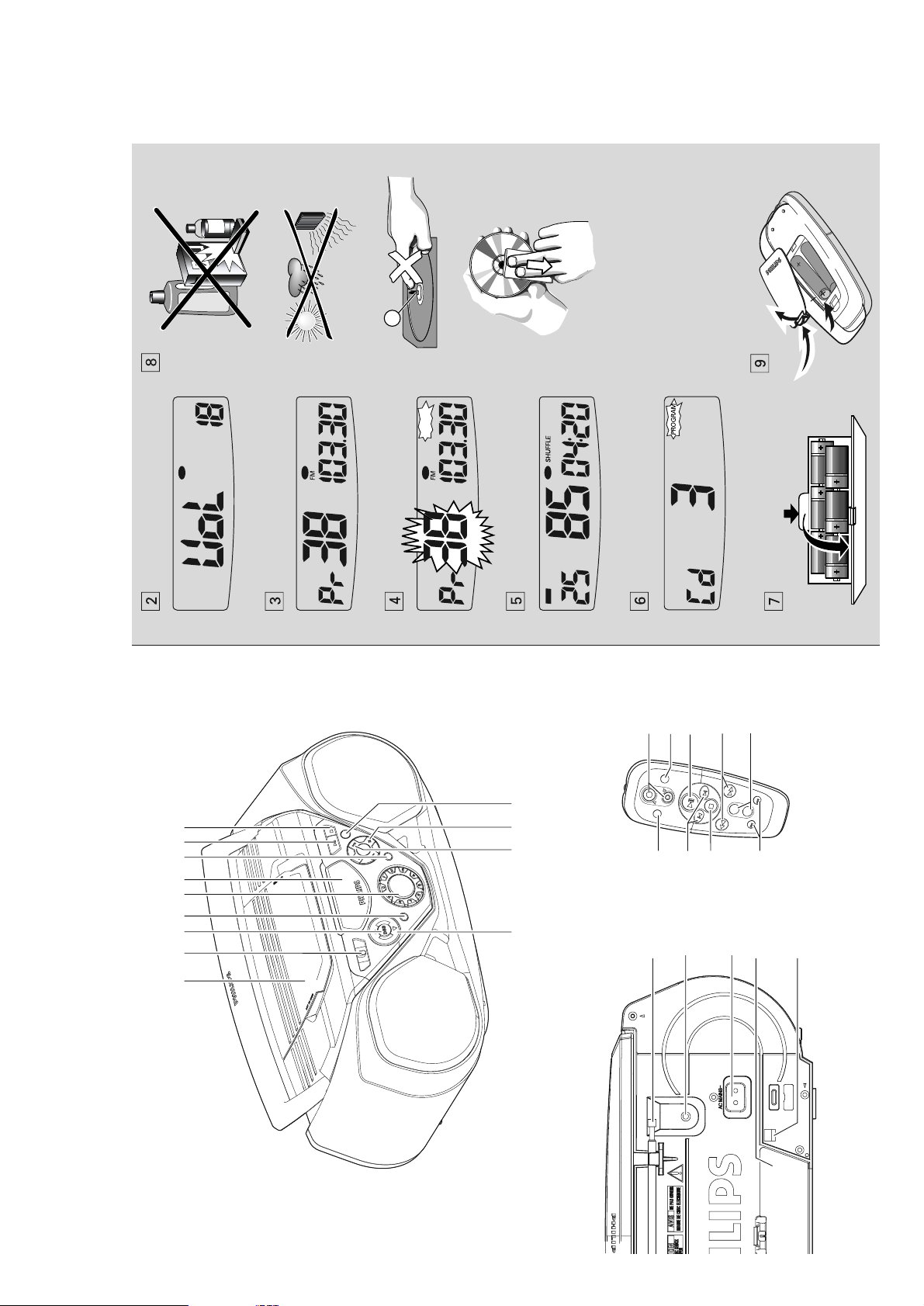
TOP AND FRONT PANEL (See
1
)
1
LIFT TO OPEN - lift here to open MP3-CD door.
2 POWER
OFF/TUNER/CD
-
selects CD/TUNER
function and also the power off switch (POWER
OFF)
3 DBB (Dynamic Bass Boost) -
activates a more vivid
bass response
4 CD MODE/BAND
- selects different play modes: e.g. REPEAT or
SHUFFLE (random) order
- selects waveband
5 0-9: - digit panel
MP3/CD: track selection and direct playback
TUNER: selecting a preset station
6 Display - shows the status of the set.
7 PROG
MP3/CD: programs tracks and reviews the
program;
TUNER
:
-
programs preset radio stations.
8 2; - starts or pauses
MP3/CD
playback.
9 9 - stop
MP3/CD
playback;
- erases a
MP3/CD
program.
0
Remote Sensor - infrared sensor for remote
control!ALBUM (+, -)
MP3 only:
selects previous/next album
TUNER:
selects the previous /next preset station
@ SEARCH , §
§
MP3/CD: - searches backward / forward within
a track;
- skips to the beginning of a current
track/ previous/ later track
TUNER:
- (down, up) tunes to radio stations.
#
VOLUME 3 , 4 -
to adjust volume level up/down
BACK PANEL
$
Telescopic aerial - improves FM reception.
% p
- 3.5 mm stereo headphone socket.
Note: The speakers will be muted when headphones
are connected to the set.
^
AC MAINS - inlet for mains lead.
& Battery compartment - for 6 batteries, type R-14,
UM2 or C-cells.
REMOTE CONTROL
1 VOLUME 3 , 4 - adjusts volume level.(up, down)
2 SHUFFLE - plays all CD tracks in random order.
3 2;
- starts CD playback;
- pauses CD playback
4 SEARCH 5 , 6 - searches backwards/
forwards within a track.
5 PRESET +,- (up, down)
TUNER:
selects a preset radio station
MP3 only: selects previous/next album
6 TUNING , §
§
(down, up) - tunes to tuner stations.
7 9 - stop MP3/CD playback;
- erases a MP3/CD program.
8 ¡ , ™ - skips to the beginning of a current track
previous/ subsequent track.
9 REPEAT - repeats a track /program/ entire CD.
CAUTION
Use of controls or adjustments or performance
of procedures other than herein may result in
hazardous radiation exposure or other unsafe
operation.
POWER SUPPLY
Whenever convenient, use the AC power supply to
conserve battery life. Make sure you remove the
power plug from the set and wall outlet before
inserting batteries.
Batteries (not included)
• Insert 6 batteries, type R-14, UM-2 or C-cells,
(preferably alkaline) with the correct polarity. (See
7
)
• Remote control
Insert 2 batteries, type AAA, R03 or UM4
(preferably alkaline). (See
9
)
IMPORTANT!
•
Incorrect use of batteries can cause electrolyte
leakage and will corrode the compartment or cause
the batteries to burst.
•
Do not mix battery types:
e.g. alkaline with carbon
zinc. Only use batteries of the same type for the set.
•When inserting new batteries, do not try to mix old
batteries with the new ones.
•
Batteries contain chemical substances, so
they should be disposed of properly.
Using AC Power
1.
Check if the AC power supply, as shown on the
type plate located on the bottom of the set,
corresponds to your local power supply. If it does
not, consult your dealer or service centre.
2.
Connect the mains lead to the wall socket.
3.
To disconnect the mains supply, unplug the set
from the wall socket.
The type plate is located on the bottom of the set.
This set complies with the radio interference
requirements of the European Community.
For users in the U.K., please follow the boxed
instructions ‘Important notes…’ on this sheet.
BASIC FUNCTIONS
Switching on and off and selecting function
1.
To switch on, adjust the POWER OFF/TUNER/CD
to select: CD or TUNER function, and operate the
respective function controls.
• On and then tu or Cd are shown briefly when you
switch on to the selected function.
2.
To switch off, adjust the POWER OFF/TUNER/CD
to select POWER
OFF.
Note :
The DBB setting, tuner presets and the volume (up
to volume level 20) will be retained in the set’s memory.
Adjusting volume and sound (See
2
)
1.
Adjust the volume with the VOLUME controls.
™ Display shows the volume level
UoL
and a
number from 0-32.
2.
Press DBB once or more to select dynamic bass
boost on or off.
DIGITAL TUNER
Tuning to radio stations
1.
Adjust the POWER OFF/TUNER/CD to TUNER.
™ tu is displayed briefly and then the radio
station frequency, waveband and, if programmed,
a preset number are shown. (See
3
)
2.
Press CD MODE/BAND once or more to select
your waveband.
3.
Press and hold SEARCH
or §
§
until the
frequency in the display starts running.
™ The radio automatically tunes to a station of
sufficient reception. Display shows Srch
during automatic tuning.
4.
Repeat step 3 if necessary until you find the
desired station.
To tune to a weak station, press
or §
§
briefly
and repeatedly until you have found optimal reception.
To improve radio reception:-
• For
FM
, extend, incline and turn the telescopic
aerial. Reduce its length if the signal is too strong.
• For
MW (AM)/LW
, the set uses a built-in aerial.
Direct this aerial by turning the whole set.
Programming radio stations
You can store up to a total of 40 radio stations in the
memory, manually or automatically (Autostore).
Manual programming
1.
Tune to your desired station (see Tuning to radio
stations).2.Press PROG to activate programming.
™ Display: Pr -- and PROGRAM flashes.
3.
Use the digit panel on the set to key in a number,
1-40, to select a preset station. E.g. press 1,1 if you
want to store your station as preset 11.(See
4
)
Note :
If a higher preset number, 41-49 is selected, the
display will show noPr and tune to Pr 4. Presets
exceeding 50, e.g. 67 will tune you to presets 6 and 7.
• Remote control: Press
PRESET + / -
once or
more to select a preset station.
•
Set: press ALBUM (
+ / -
)
4.
Press PROG to confirm.
English
CONTROL/POWER SUPPLY POWER SUPPLY DIGITAL TUNER
CONNECTIONS AND CONTROLS

3 - 3
5.
Repeat steps 1-4 to store other stations.
Note :
You can erase a preset station by storing
another frequency in its place.
Autostore
Autostore automatically starts programming radio
stations from preset 1. Available stations are
programmed in order of waveband reception strength:
FM, followed by MW (AM). Any previous presets e.g.
manually programmed will be erased.
•Press PROG for 4 seconds or more to activate
autostore programming.
™ The display shows Auto,
PROG
blinks,
followed by the radio station details when
stored.
After all stations are stored, the first preset station
will then automatically play.
To listen to a preset station
•
Set: press ALBUM (
+ / -
)
• Direct Easy Access: use the digit panel on the set
to key in a number, 1-40, to select a preset station.
• Remote control: optionally, press
PRESET + ,-
to
select your preset station.
MP3-CD PLAYER
IMPORTANT SPECIFICATIONS
Supported formats:
• Disc format ISO9660, Joliet and multi-session CDs.
Use ISO9660 disc format when burning CD-ROM.
• MP3 music fomats.
• MP3 bit rate (data rate): 32-320 Kbps and variable
bit rate.
• 650Mb and 700Mb CD-R and CD-RWs.
• Directory nesting up to a maximum of 8 levels
(max. 64 characters).
General information
The music compression technology MP3 (MPEG Audio
Layer 3) reduces the original digital audio data by a
factor up to 10 without losing significant sound quali-
ty. This allows you to record up to 10 hours of CD-like
quality music on a single CD-ROM.
How to get MP3 music
Either download legal MP3 music from the internet or
convert your audio CD into MP3 format with any MP3
encoder software, and then record onto a CD-R(W).
• To achieve a good sound quality a bit rate of at
least 128kbps is recommended for MP3 files.
When burning the MP3-CD
• Make sure the file names of the MP3 files end with
.mp3
• Use a writing software capable of recording MP3
track titles (files) in numerical and alphabetical
order. For details on using the software, refer to
the operating instructions of the software.
• Some encoder software offer an option to protect
music files, i.e. the files can only be played on the
computer which created them. If you burn such
files on a CD-ROM, you cannot play them on this
unit. Make sure to deactivate the protection option
in the encoder software before creating the music
files. In this case you are responsible for adherence
to all local or international copyrights.
How to organize MP3 files
You can store up to a maximum number of 35 albums
and 400 titles on one MP3-CD, depending on the song
file sizes.
Albums and titles are alphabetically sorted.
• MP3-CD/ CD albums and titles are shown as num-
bers in the display.
IMPORTANT!
This set does not play/support the following:
• Empty albums: an empty album is an album that
does not contain MP3 files, and will not be shown
in the display.
• Non-supported file formats are skipped. This
means that e.g.: Word documents .doc or MP3
files with extension .dlf are ignored and will not be
played.
• Playlist Files e.g. .m3u, .pls of WMA, AAC,
Winamp, Sonic, RealJukebox, MS Mediaplayer 7.0,
MusicMatch.
• Recordings created on e.g. PacketWriting and
Package Writing.
MP3/CD display indications
™ rEAd when reading disc contents;
™ nO dISc if no CD inserted/ CD dirty,
incorrectly inserted or damaged.
™ Cd throughout CD operation
™ MP3,
TRACK, ALBUM throughout MP3-CD operation
™ In CD stop mode: total track number and total
playback time
™ If MP3-CD, the album number is also shown.
™ nF dISc if you have inserted a non-finalized
CD-R(W).
™ nO ALb if no albums are available.
Playing disc
This set plays Audio Discs including CDR(W)s, and
mp3 CD-ROMs.
1.
Adjust the POWER OFF/TUNER/CD to CD.2.Insert a CD with the printed side facing up and
close the door.
Note:
MP3-CDs may more than take 10 seconds to
read.
3.
Press
2;
to start playback.
4.
To pause playback press
2;
. Press
2;
again to
resume play.
™ Display: elapsed playtime flashes during pause.
5.
To stop playback, press
9
.
Note : CD play will also stop when:
- the CD door is opened
- the CD has reached the end
- you select TUNER/POWER
OFF
.
Selecting a different track
There are 2 ways:
Direct Easy Access:
• Key in the number of the track using the digit
keyboard on the set.
Note: If you key in a number larger than the maximum
track number, your input is ignored and the current
track continues playing.
SEARCH
or
§
§
•Press SEARCH
or
§
§
once or repeatedly to
select your track.
•To skip tracks rapidly press and hold SEARCH
or
§
§
.
MP3-CD mode only:
First press ALBUM, PRESET
+
or
-
once or more to
find your album.
Finding a passage within a track
1.
Press and hold SEARCH
or §
§
.
– The MP3/CD is played at high speed.
2.
When you recognize the passage you want,
release
or §
§
to resume normal playback.
Note:
Searching is only possible within a track. The set goes
into pause/stop mode when the end/start of a track is
reached during searching.
Different play modes: SHUFFLE and REPEAT
You can select and change the various play modes
before or during playback, and combine the modes
with PROGRAM. (See
5
)
SHUFFLE
- tracks of the entire CD/ program are played
in random order
SHUFFLE REPEAT ALL
- to repeat the entire CD/ program
continuously in random order
REPEAT ALL
- repeats the entire CD/ program
REPEAT
- plays the current track continuously
1.
To select play mode, press CD MODE/BAND
once or more.
2.
Press
2;
to start playback if in the stop position,
unless you have chosen a shuffle option.
3.
To select normal playback, press CD MODE/BAND
repeatedly until the various modes are no longer
displayed.
–
You can also press the
9
button to cancel your play
mode.
DIGITAL TUNER MP3-CD PLAYER MP3-CD PLAYER MP3-CD PLAYER
INSTRUCTIONS FOR USE

3 - 4
No sound /power
–
Volume not adjusted
• Adjust the VOLUME
–
Mains lead not securely connected
• Connect the AC mains lead properly
–
Batteries exhausted/ incorrectly inserted
• Insert (fresh) batteries correctly
–
Headphones connected to the set
• Disconnect headphones
--
CD contains non-audio files
•Press SEARCH
or §
§
. once or more to skip to a
CD audio track, instead of the data file
Severe radio hum or noise
–
Electrical interference: set too close to TV, VCR or
computer
•Move the set to increase the distance
Poor radio reception
–
Weak radio signal
• FM: Adjust the FM telescopic aerial
noPr indication
–
During programming radio preset stations, you have
keyed in a preset number that exceeds the maximum
preset number i.e. 40
• Key in a preset number from 1-40
nOdISc indication
–
CD badly scratched or dirty
•
Replace/ clean CD, see Maintenance
–
Laser lens steamed up
•Wait until lens has cleared
nFdISc indication
–
CD-R(W) is blank/ not finalized
•
Use a finalized CD-R(W)
Sound skips during MP3 playback
--
MP3 file made at compression level exceeding
320kbps
• Use a lower compression level to record CD tracks
into MP3 format
Cannot find desired MP3 title
--
Wrong file extension used and/ or file name with
unsuitable text characters used
•Make sure the file names are typed in English text
characters an that the MP3 files end with .MP3
The CD skips tracks
–
CD damaged or dirty
• Replace or clean CD
–
SHUFFLE or PROGRAM is active
• Switch off SHUFFLE / PROGRAM
Remote control does not function properly
–
Batteries exhausted/ incorrectly inserted
• Insert (fresh) batteries correctly
–
Distance/ angle between the set too large
• Reduce the distance/ angle
Programming track numbers
In the stop position, select and store your CD tracks in
the desired sequence. Up to 20 tracks can be stored in
the memory.
1.
Press SEARCH
or §
§
on the set to select your
desired track number.
MP3-CD mode only:
First press ALBUM, PRESET
+
or
-
once or more to
find your album.
2.
Press PROG.
™ Display:
PROGRAM
and Prog.(See
6
)
™ If you attempt to program without first
selecting a track number, nOSEL is shown.
3.
Repeat steps 1-2 to select and store all desired
tracks.
™ Display: FuLL if you try to program more
than 20 tracks.
Reviewing the program
In the stop position, press and hold PROG until the
display shows all your stored track numbers in
sequence.
Erasing a program
You can erase the program by:
•pressing
9
twice
™ CLr is displayed briefly and
PROG
disappears.
•You select TUNER /POWER OFF.
SAFETY & MAINTENANCE INFORMATION
(See
8
)
• Don’t expose the set, batteries or CDs to humidity,
rain, sand or excessive heat.
•Clean the set with a dry cloth. Don't use any
cleaning agents containing alcohol, ammonia,
benzene or abrasives as these may harm the set.
•Place the set on a hard and flat surface so that the
system does not tilt. Make sure there is good
ventilation to prevent the set overheating.
•The mechanical parts of the set contain self-
lubricating bearings and must not be oiled or
lubricated.
CD player and CD handling
•If the CD player cannot read CDs correctly, use a
cleaning CD to clean the lens before taking the set
to repair.
• The lens of the CD player should never be touched!
• Sudden changes in the surrounding temperature
can cause condensation on the lens of your CD
player. Playing a CD is then not possible. Do not
attempt to clean the lens but leave the set in a
warm environment until the moisture evaporates.
•Always close the CD door to avoid dust on the lens.
•To clean the CD, wipe in a straight line from the
centre towards the edge using a soft, lint-free
cloth. Do not use cleaning agents as they may
damage the disc.
• Never write on a CD or attach any stickers to it.
MP3-CD PLAYER SAFETY AND MAINTENANCE TROUBLESHOOTING
WARNING:
Do not open the set as there is a risk of electric shock. Under no
circumstances should you try to repair the set yourself, as this will
invalidate the guarantee.
If a fault occurs, first check the points listed below before taking the set for repair.
If you are unable to remedy a problem by following these hints, consult your dealer or service centre.
Environmental information
We have done our best to reduce the packaging and make it easy to separate into 3 materials:
cardboard, expandable polystyrene, polyethylene.
Your set consists of materials which can be recycled if disassembled by a specialized company.
Please observe the local regulations regarding the disposal of packaging, exhausted
batteries and old equipment.
INSTRUCTIONS FOR USE
3 - 5
VARICAP ALIGNMENT
FM RF
FM IF
VCO
AM IF
AM RF
3)
108MHz
87.5MHz
(65.81MHz)
87.5MHz
(65.81MHz)
87.5MHz
(65.81MHz)
279kHz
153kHz
1602kHz
531kHz
5130
check
5122
check
5123
check
8V –0.2V
4.3V –0.5V
(1.2V –0.5V)
8V –0.2V
1.1V –0.4V
8V –0.2V
1.1V –0.4V
1494kHz
558kHz
560kHz
1500kHz
5105
LW ferrite coil
198kHz
1494kHz
558kHz
560kHz
1500kHz
198kHz
2106
5104
MW ferrite coil
5104
MW ferrite coil
2106
3142 152kHz –1kHz
1)
98MHz
5112
MAX
FM
87.5 - 108MHz
(65.81 - 74, 87.5 - 108MHz)
LW
153 - 279kHz
MW
FM/MW/LW- version, 9kHz grid
531 - 1602kHz
1700kHz
530kHz
5123
check
8V –0.2V
1.1V –0.4V
1602kHz
531kHz
5123
check
6.9V –0.2V
1.1V –0.4V
108MHz
108MHz 2155
5131
MW
FM/AM-version, 10kHz grid
530 - 1700kHz
FM
MW
LW
98MHz, 1mV
continuous wave
450kHz
connect pin 6 of
IC 7101 (AM Osc.)
with 2.2k‰ to Vcc
Use Service Testprogram. By selecting the TUNER TEST test frequencies will be stored as preset frequencies automatically.
4
1
3
5
5
A
A
5119FM
10.7MHz, 45mV
continuous wave
2D
mod=1kHz
∆f=–22.5kHz
1)
If sensitivity of frequency counter is too low adjust to max. channel separation
(input signal: stereo left 90% + 9%, adjust output on right channel to minimum)
Repeat
ECO6, general with ferrite antenna, 070799
TUNER ADJUSTMENT TABLE ( ECO6 FM/MW- and FM/MW/LW - versions with ferrite antenna)
∆f=–10kHz
VRF = 0.5mV
C
see
remark
2)
220R
100nF
36
IC 7101
220R
100nF
40
IC 7101
2141
shortcircuit
to block AFC
21
IC 7101
max.
symmetric
f
o
AM AFC
MW
C
continuous wave
VRF = 2mV
5111
5114
2
0 – 2 mV DC
0 – 3 mV DC
MW
FM/MW/LW- and FM/MW-version
( 9kHz grid)
531 - 1602kHz
B
∆f = –30kHz
VRF as low as
possible
max.
symmetric
f
o
MW
FM/AM-version, 10kHz grid
530 - 1700kHz
2)
RC network serves for damping the IF-filter while adjusting the other one.
3)
LW has to be aligned before MW.
Waverange Input frequency Input Tuned to Adjust Output Scope/Voltmeter
FM
87.5 - 108MHz
(65.81 - 74, 87.5 - 108MHz)
FM/MW-version, 9kHz grid
531 - 1602kHz
(as low as
possible)

4 - 14 - 1
SERVO PROCESSOR SAA7325H
SYMBOL PIN DESCRIPTION
HFREF 1 comparator common mode input
HFIN 2 comparator signal input
ISLICE 3 current feedback output from data slicer
V
SSA1
4
(1)
analog ground 1
V
DDA1
5
(1)
analog supply voltage 1
I
ref
6 reference current output pin
V
RIN
7 reference voltage for servo ADC’s
D1 8 unipolar current input (central diode signal input)
D2 9 unipolar current input (central diode signal input)
D3 10 unipolar current input (central diode signal input)
D4 11 unipolar current input (central diode signal input)
R1 12 unipolar current input (satellite diode signal input)
R2 13 unipolar current input (satellite diode signal input)
V
SSA2
14
(1)
analog ground 2
CROUT 15 crystal/resonator output
CRIN 16 crystal/resonator input
V
DDA2
17
(1)
analog supply voltage 2
LN 18 DAC left channel differential output - negative
LP 19 DAC left channel differential output - positive
V
neg
20 DAC negative reference input
V
pos
21 DAC positive reference input
RN 22 DAC right channel differential output - negative
RP 23 DAC right channel differential output - positive
SELPLL 24 selects whether internal clock multiplier PLL is used
TEST1 25 test control input 1; this pin should be tied LOW
CL16 26 16.9344 MHz system clock output
DATA 27 serial d4(1)ata output (3-state)
WCLK 28 word clock output (3-state)
SCLK 29 serial bit clock output (3-state)
EF 30 C2 error flag output (3-state)
TEST2 31 test control input 2; this pin should be tied LOW
KILL 32 kill output (programmable; open-drain)
V
SSD1
33
(1)
digital ground 2
V2/V3 34 versatile I/O: input versatile pin 2 or output versatile pin 3 (open-drain)
WCLI 35 word clock iutput (for data loopback to DAC)
SDI 36 serial data input (for data loopback to DAC)
SCLI 37 serial bit clock input (for data loopback to DAC)
RESET 38 power-on reset input (active LOW)
SDA 39 microcontroller interface data I/O line (open-drain output)
SCL 40 microcontroller interface clock line input
SERVO PROCESSOR SAA7325H
SYMBOL PIN DESCRIPTION
RAB 41 microcontroller interface R/W and load control line input (4-wire bus mode)
SILD 42 microcontroller interface R/W and load control line input (4-wire bus mode)
STATUS 43 servo interrupt request line/decoder status register output (open-drain)
TEST3 44 test control input 3; this pin should be tied LOW
RCK 45 subcode clock input
SUB 46 P-to-W subcode bits output (3-state)
SFSY 47 subcode frame sync output (3-state)
SBSY 48 subcode block sync output (3-state)
CL11/4 49 11.2896 MHz or 4.2336 MHz (for microcontroller) clock output
V
SSD2
50
(1)
digital ground 3
DOBM 51 bi-phase mark output (externally buffered; 3-state)
V
DDD1(P)
52
(1)
digital supply voltage 2 for periphery
CFLG 53 correction flag output (open-drain)
RA 54 radial actuator output
FO 55 focus actuator output
SL 56 sledge control output
V
DDD2(C)
57
(1)
digital supply voltage 3 for core
V
SSD3
58
(1)
digital ground 4
MOTO1 59 motor output 1; versatile (3-state)
MOTO2 60 motor output 2; versatile (3-state)
V4 61 versatile output pin 4
V5 62 versatile output pin 5
V1 63 versatile intput pin 1
LDON 64 laser drive on output (open-drain)
Note : All supply pins must be connected to the same external power supply voltage.
Abbreviations and Pin-description of CD ICs Abbreviations and Pin-description of CD ICs
 Loading...