

Philips AZ-1510 Service Manual
CD RCR Soundmachine
AZ 1510
AZ 1515
all versions
Handling Chip Components and Safety ..........................1 - 1
Technical Specification & Measurement Setup...............2 - 1
Service Measurement......................................................2 - 2
Connections and controls................................................3 - 1
Service tools....................................................................3 - 2
Disassembly Diagram......................................................4 - 1
CD Service Test program.....................................4 - 2 .. 4 - 3
Block Diagram .................................................................5 - 1
Wiring Diagram................................................................5 - 2
Front Board
circuit diagram.........................................................6 - 1
layout diagram.........................................................6 - 2
Combi Board - Tuner part
circuit diagram.........................................................7 - 1
layout diagram.........................................................7 - 2
Tuner adjustment ....................................................7 - 2
Combi Board - CD part
circuit diagram - 1 ...................................................8 - 1
circuit diagram - 2 ...................................................8 - 2
Combi Board - Tape part
circuit diagram.........................................................9 - 1
Combi Board - Audio/supply part
circuit diagram.........................................................9 - 2
Combi Board
layout diagram (copper side).................................10 - 1
layout diagram (component side)..........................10 - 2
Exploded view - cabinet.................................................11 - 1
Exploded view - tape deck ............................................11 - 2
Tape deck adjustment...................................................11 - 2
Mechanical partslist.......................................................11 - 2
Electrical partslist ...........................................12 - 1 .. 12 - 10
© 3140 785 32240
Published by LX 0304 Service Audio Printed in The Netherlands Subject to modification
CLASS 1
LASER PRODUCT
TABLE OF CONTENTS
©
Copyright 2001 Philips Consumer Electronics B.V. Eindhoven, The Netherlands
All rights reserved. No part of this publication may be reproduced, stored in a retrieval
system or transmitted, in any form or by any means, electronic, mechanical, photocopying,
or otherwise without the prior permission of Philips.
1 - 1
©
©
©
WARNING
All ICs and many other semiconductors are susceptible to
electrostatic discharges (ESD). Careless handling during
repair can reduce life drastically.
When repairing, make sure that you are connected with the
same potential as the mass of the set via a wristband with
resistance. Keep components and tools at this potential.
ATTENTION
Tous les IC et beaucoup d˙autres semi-conducteurs sont
sensibles aux d charges statiques (ESD). Leur long vite
pourrait tre consid rablement court e par le fait qu˙aucune
pr caution n st prise leur manipulation.
Lors de r parations, s˙assurer de bien tre reli au mme
potentiel que la masse de l˙appareil et enfileer le bracelet
serti d˙une r sistance de s curit .
Veiller ce que les composants ainsi que les outils que l˙on
utilise soient galement ce potentiel.
d
d
WARNUNG
Alle ICs und viele andere Halbleiter sind empfindlich
gegen ber elektrostatischen Entladungen (ESD).
Unsorgf ltige Behandlung im Reparaturfall kann die
Lebensdauer drastisch reduzieren.
Sorgen Sie daf r, da⁄ Sie im Reparaturfall ber ein Pulsarmband mit Widerstand mit dem Massepotential des
Ger tes verbunden sind.
Halten Sie Bauteile und Hilfsmittel ebenfalls auf diesem
Potential.
ñ
ñ
WAARSCHUWING
Alle IC˙s en vele andere halfgeleiders zijn gevoelig voor
electrostatische ontladingen (ESD).
Onzorgvuldig behandelen tijdens reparatie kan de levensduur
drastisch doen vermindern. Zorg ervoor dat u tijdens reparatie
via een polsband met weerstand verbonden bent met hetzelfde
potentiaal als de massa van het apparaat.
Houd componenten en hulpmiddelen ook op ditzelfde potentiaal.
AVVERTIMENTO
Tutti IC e parecchi semi-conduttori sono sensibili alle scariche
statiche (ESD).
La loro longevit potrebbe essere fortemente ridatta in caso di
non osservazione della pi grande cauzione alla loro
manipolazione. Durante le riparationi occorre quindi essere
collegato allo stesso potenziale che quello della massa
del pparecchio tramite un braccialetto a resistenza.
Assicurarsi che i componenti e anche gli utensili con quali si
lavora siano anche a questo potenziale.
Safety regulations require that the set be restored to its
original condition and that parts which are identical with
those specified be used.
Safety components are marked by the symbol
Le norme di sicurezza estigono che l˙apparecchio venga
rimesso nelle condizioni originali e che siano utilizzati i
pezzi di ricambiago identici a quelli specificati.
Componenty di sicurezza sono marcati con
Veiligheidsbepalingen vereisen, dat het apparaat in zijn
oorspronkeliijke toestand wordt teruggebracht en dat
onderdelen, identiek aan de gespecificeerde, worden toegepast.
De Veiligheidsonderdelen zijn aangeduid met het symbool
s Varning !
Osynlig laserstr lning n r apparaten r ppnad och
sp rren r urkopplad. Betrakta ej str len.
Advarsel !
Usynlig laserstr ling ved bning n r sikkerhedsafbrydere
er ude af funktion. Undg udsaettelse for str ling.
Varoitus !
Avatussa laitteessa ja suojalukituksen ohitettaessa olet alttiina
n kym tt m lle laseris teilylle. l katso s teeseen !
"Pour votre s curite, ces documents doivent tre utilis s par
des sp cialistes agr s, seuls habilit s r parer votre
appareil en panne".
ESD
SAFETY
Bei jeder Reparatur sind die geltenden Sicherheitsvorschriften zu beachten. Der Originalzustand des Ger tes
darf nicht ver ndert werden. F r Reparaturen sind Originalersatzteile zu verwenden.
Sicherheitsbauteile sind durch das Symbol markiert.
Les normes de s curit exigent que lappareil soit remis
ltat dorigine et que soient utilises les pi ces de
rechange identiques celles sp cifi es.
Les composants de s curit sont marqu s
CLASS 1
LASER PRODUCT
DANGER: Invisible laser radiation when open.
After servicing and before returning the set to customer
perform a leakage current measurement test from all
exposed metal parts to earth ground, to assure no
shock hazard exists.
The leakage current must not exceed 0.5mA.
AVOID DIRECT EXPOSURE TO BEAM.
f
f
i
i
∂
ß
f
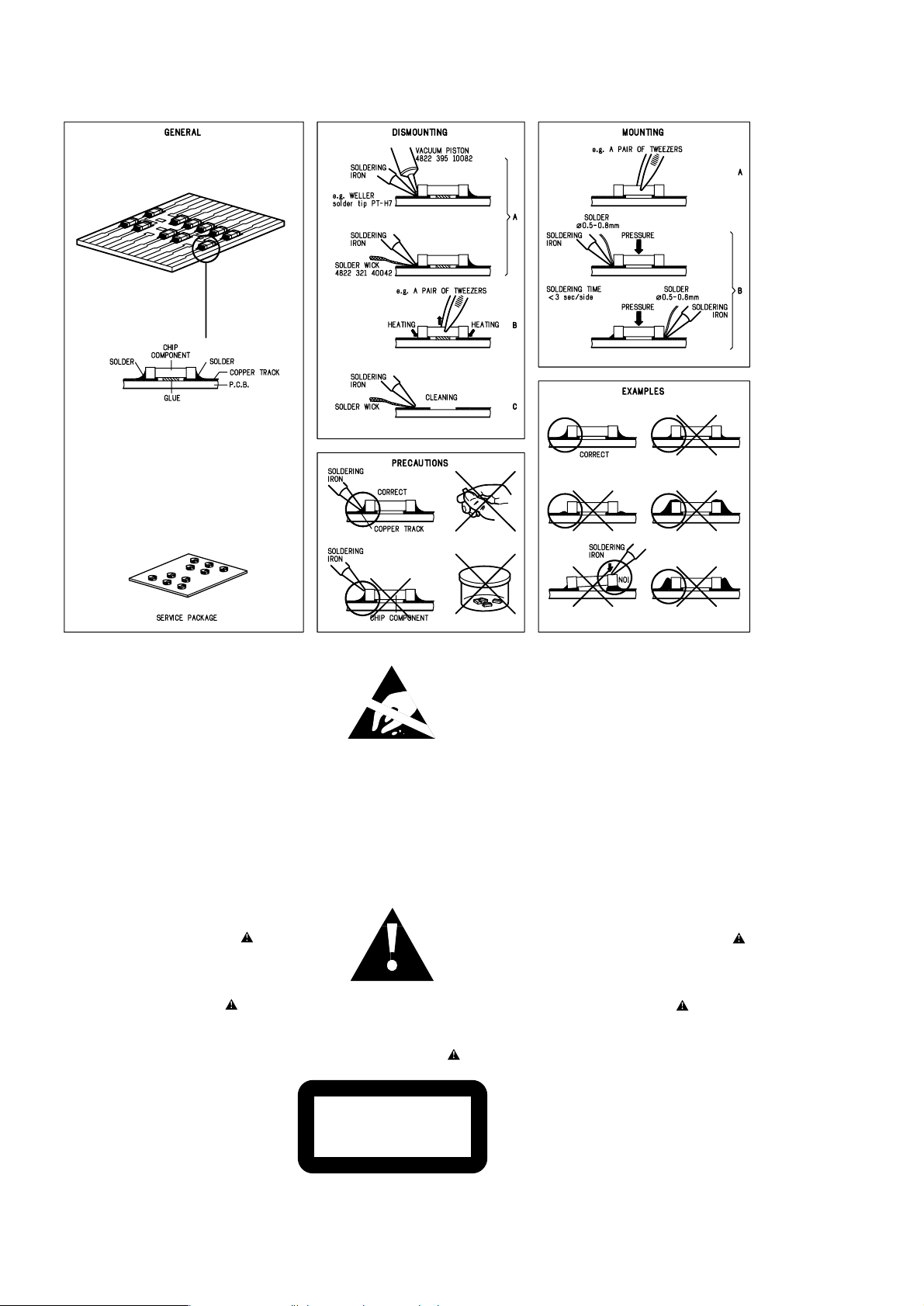
HANDLING CHIP COMPONENTS

TECHNICAL SPECIFICATIONS
GENERAL
Mains voltage -/00C/05 : 230 V
-/01 : 120 / 230 V
-/13 : 220V
-/17 : 120 V
Mains frequency -/00C/05/13 : 50 Hz
-/01 : 50 / 60 Hz
-/17 : 60 Hz
Battery main set : 9 V (R14 x 6)
remote : 3V (R6 x 2)
Power consumption : < 30 W (max.)
Dimension (W x H x D) : 405 x 162 x 232 mm
Weight : 2.9 Kg
AMPLIFIER
Output power mains : 2 x 1 W
battery : 2 x 1 W
Speaker impedance : 2 x 8 o hm
Frequency response : 60 Hz - 2 0 kHz (±3dB)
TUNER - FM SECTION
Tuning range : 87.5 - 108 MHz
IF frequency : 10.7 MHz ± 0.2 MHz
Sensitivity : 20 dBf at 26dB S/N
Selectivity : 24 dB at 300kHz
IF rejection : 85 dB
Image rejection : 24 dB
SPECIFICATIONS
TUNER - AM SECTION
Tuning range MW : 531 - 1602 kHz
-/17 : 530 - 1700 kHz
LW : 153 - 279 kHz
IF frequency : 450 kHz ± 1 kHz
Sensitivity MW : 3200 µV/m at 26dB S/N
LW : 5500 µV/m at 26dB S/N
Selectivity MW : 22 dB
LW : 29 dB
IF rejection MW : 64 dB
LW : 60 dB
Image rejection MW : 32 dB
LW : 38 dB
AUDIO CASSETTE RECORDER
Number of tracks :1 stereo
Tape speed : 4.76 cm/sec ± 3%
Wow & flutter : < 0.48 JIS UWTD
Fast wind/ rewind C60 : < 110 sec.
Frequency response P/B : 125 - 8000 Hz
S/N ratio : > 36 dB (R/P)
Erasing ratio : > 50 dB
Bias frequency : 73 ± 1.5 kHz
COMPACT DISC
Frequency response : 100 Hz - 10 kHz ± 2dB
S/N ratio : 60 dB
Channel difference 1 kHz : 2 dB
Channel crosstalk 1 kHz : 40 dB
Laser wavelength : 780 ± 20 nm
Laser light power : < 0.5 mW
2 - 1
2 - 2
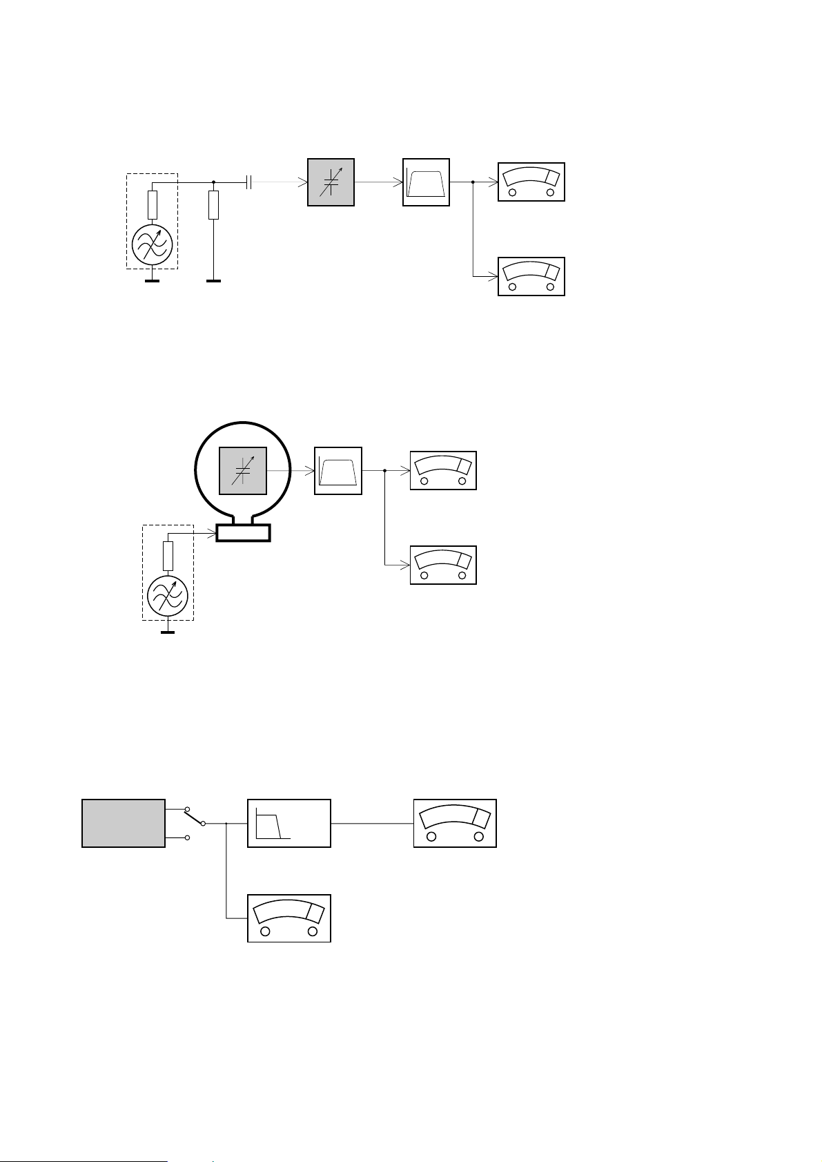
SERVICE MEASUREMENT
Bandpass
250Hz-15kHz
e.g. 7122 707 48001
LF Voltmeter
e.g. PM2534
DUT
RF Generator
e.g. PM5326
S/N and distortion meter
e.g. Sound Technology ST1700B
Tuner SW
To avoid atmospheric interference all AM-measurements have to be carried out in a Faraday«s cage.
Use a bandpass filter (or at least a high pass filter with 250Hz) to eliminate hum (50Hz, 100Hz).
Ri=50Ω
Aerial replacement
Capacitor
R=50Ω
Bandpass
250Hz-15kHz
e.g. 7122 707 48001
LF Voltmeter
e.g. PM2534
DUT
S/N and distortion meter
e.g. Sound Technology ST1700B
Frame aerial
e.g. 7122 707 89001
Tuner AM (MW,LW)
To avoid atmospheric interference all AM-measurements have to be carried out in a Faraday«s cage.
RF Generator
e.g. PM5326
Ri=50Ω
Low pass filter 22kHz
L
R
LEVEL METER
e.g. Sennheiser UPM550
with FF-filter
S/N and distortion meter
e.g. Sound Technology ST1700B
DUT
CD
Use Audio Signal Disc SBC429 4822 397 30184 (replaces test disc 3)
L.P.F. = 13
th
order filter 4822 395 30204
3 - 1
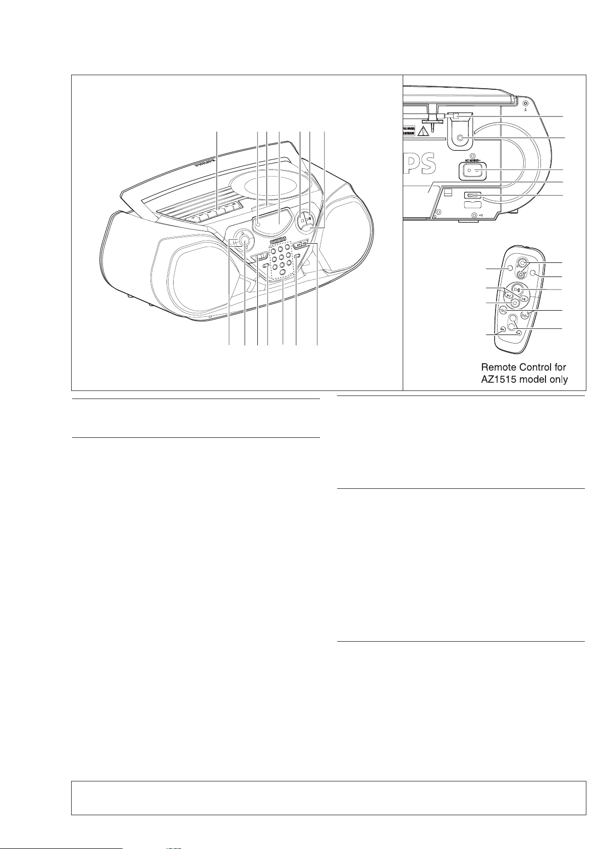
ACCESSORIES
1 x AC mains lead
1 x Remote Control (for AZ1515 model only)
TOP AND FRONT PANEL (See 1)
1 VOLUME 3 , 4 - to adjust volume level.
2 DBB (Dynamic Bass Boost) - activates a more vivid bass response.
3 POWER slider - selects TAPE/ RADIO / CD function and also the power off switch
(TAPE/ OFF).
4 BAND - selects waveband.
5 0-9: - digit panel
CD: - track selection and direct playback;
RADIO: -
selecting a preset station.
6 PROGRAM
CD: -
programs tracks and reviews the program;
Tuner: -
programs preset radio stations.
7 SEARCH ∞ , §
CD: - searches backward and forward within a track;
- skips to the beginning of a current track/ previous/ later track.
RADIO: -
(down, up) tunes to radio stations.
8 MODE - selects different play modes: e.g. REPEAT or SHUFFLE (random) order.
9 2; - starts or pauses CD playback.
0 9 - to stop playback;
- erases a CD program.
! Display - shows the status of the set.
@ OPEN/ CLOSE - opens/closes the CD-tape door.
# REMOTE SENSOR - (for AZ1515 model only) infrared sensor for remote control.
$ CASSETTE RECORDER keys:
RECORD 0 - to start recording.
PLAY 2 - to start playback.
SEARCH 5 / 6 - fast rewinds/ winds tape.
STOP 9 - stops tape.
PAUSE ; - pauses playback or recording.
BACK PANEL
% Telescopic aerial - improves FM reception.
^p- 3.5 mm stereo headphone socket.
Note: The speakers will be muted when headphones are connected to the set.
& AC MAINS - inlet for mains lead.
* Battery compartment - for 6 batteries, type R-14, UM2 or C-cells.
( Voltage selector (some versions only) - adjust to match the local voltage
110/220V before plugging in the set.
REMOTE CONTROL (for AZ1515 model only)
1 VOLUME 3 , 4 - adjusts volume level.
2 SHUFFLE - plays all CD tracks in random order.
3 2; - starts or pauses CD playback.
4 SEARCH 5 , 6 - searches backwards/
forwards within a track.
5 PRESET
+ ,-(up, down) - selects a preset radio
station.
6 TUNING ∞ , § (down, up) - tunes to tuner stations.
7 9 - to stop playback;
- erases a CD program.
8 ¡ , ™ - skips to the beginning of a current track previous/ subsequent track.
9 REPEAT - repeats a track /program/ entire CD.
POWER SUPPLY
Whenever convenient, use the AC power supply to conserve battery life. Make sure
you remove the power plug from the set and wall outlet before
inserting batteries.
Batteries (not included)
• Insert 6 batteries, type R-14, UM-2 or C-cells, (preferably alkaline) with the correct
polarity.
• Remote control (AZ1515 model only)
Insert 2 batteries, type AAA, R03 or UM4 (preferably alkaline).
40 PRESET DIGITALTUNER
2134
9!@#$ 0
65 7
8
CONNECTIONS AND CONTROLS
For more information onoperation instruction please visit Philips Audio internet site :
http://www.audio.philips.com
%
^
&
*
(
9
REPEAT
SHUFFLE
VOLUME
1
2
8
7
SEARCH
+
SEARCH
PRESET
-
6
TUNING
3
4
5

3 - 2
SERVICE TOOLS
Audio signal disc SBC 429.......................................................................4822 397 30184
Playability test disc SBC 444
Test disc 5 (disc without errors ) +
Test disc 5A (disc with dropout errors, black spots and fingerprints)
SBC 426/426A.....................................................................4822 397 30096
Burn in test disc (65 min. 1kHz signal at -30 dB level without “pause”)
...................................................................4822 397 30245
.....4822 397 30155
AVAILABLE ESD PROTECTION EQUIPMENT
anti-static table mat
large 1200x650x1.25mm 4822 466 10953
small 600x650x1.25m 4822 466 10958
anti-static wristband
4822 395 10223
connection box (3 press stud connections, 1MΩ) 4822 320 11307
extendible cable (2m, 2MΩ, to connect wristband to connection box) 4822 320 11305
connecting cable (3m, 2MΩ, to connect table mat to connection box) 4822 320 11306
earth cable (1MΩ, to connect any product to mat or to connection box) 4822 320 11308
KIT ESD3 (combining all 6 prior products - small table mat) 4822 310 10671
wristband tester 4822 344 13999
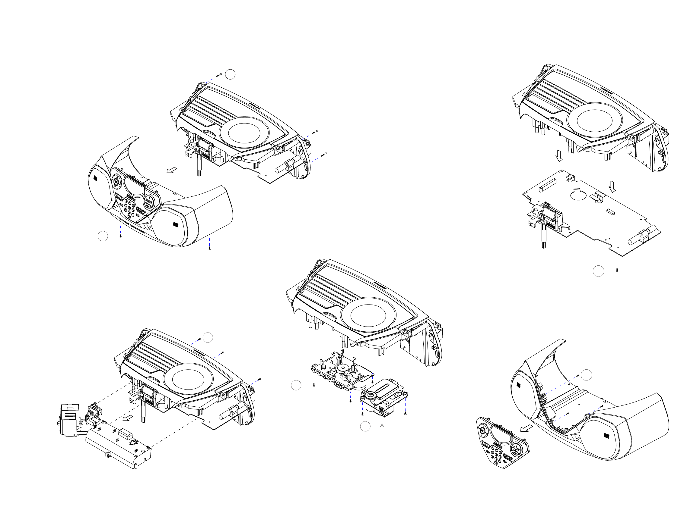
1. TO REMOVE BOTTOM CABINET ASEMBLY
A. Remove screws 3x20 - 4 pcs.
B. Remove screws 3x10 - 6 pcs.
4. TO REMOVE TAPE AND CD MECHANISM
E. Remove screws 3x10 - 4 pcs.
F. Remove screws 2.5x10 - 4 pcs.
2. TO REMOVE BATTERY COMPARTMENT ASEMBLY
C. Remove screws 3x10 - 3 pcs.
3. TO REMOVE COMBI BOARD ASEMBLY
D. Remove screws 3x10 - 7 pcs.
5. TO REMOVE CD PANEL ASEMBLY
G. Remove screws 2x8 - 4 pcs.
!(4x)
A x4
B x6
C x3
E x4
F x4
G x4
D x7
4 - 14 - 1
DISASSEMBLY DIAGRAM
4 - 2 4 - 2
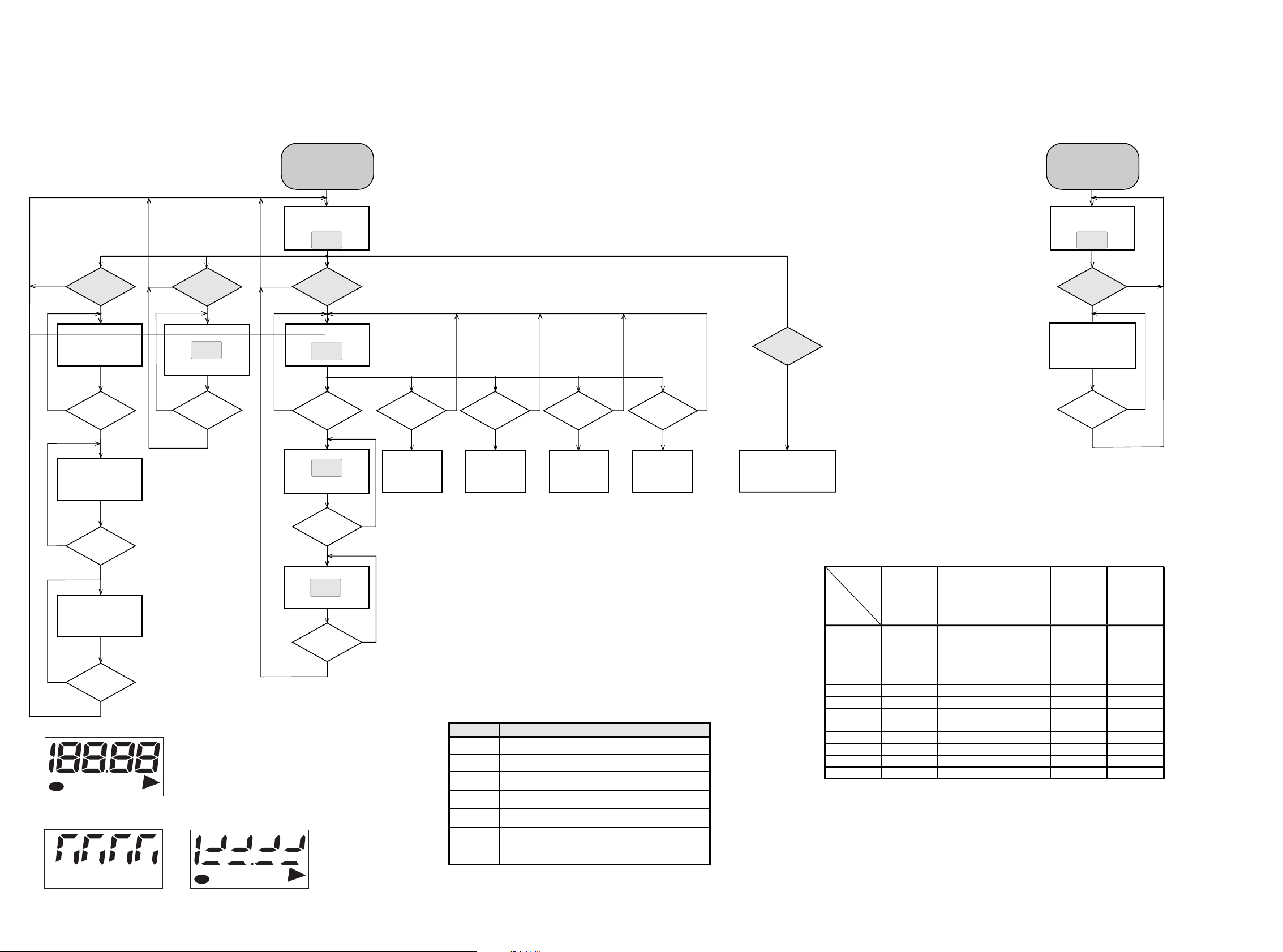
STOP button pressed in any step returns
to begin of Service Testprogram.
BAND button
pressed?
BAND button
pressed?
N
Y
Y
Display shows all
segments and flags.
see figure 1
N
Y
Display shows part
segments and flags.
see figure 2
DISPLAY TEST
CD SERVO TEST
Display shows
version number
of the µ P - software.
PLAY button
pressed?
Display shows
PLAY button
pressed?
NEXT button
pressed?
PREV. button
pressed?
VOL-DN button
pressed?
VOL-UP button
pressed?
Slide moves
outside as long as
button is held
depressed.
Slide moves
inside as long as
button is held
depressed.
YYYY Y
NNNNN
FOCUS found?
Y
N
Display shows
objective moves up&down
disc motor for 160ms "on"
STOP button
pressed?
Y
N
Display shows
disc motor turns.
FOCUS search
SLIDE MOTOR test DISC MOTOR test
To enter CD Service
Testprogramm hold
BAND & MODE buttons
depressed while switching
CD mode on.
*
*
*
To leave Service Testprogram switch mode switch
to off-position.
Door switch is ignored → CD door can be opened.
Slide servo, Radial servo, Focus servo, Disc motor
and Laser are switched off.
Mute is switched on via decoder IC.
*
Volume up/down buttons function independentely
of the service testprogram.
N
N
Display shows
version number
of the µ P - software.
To enter Service
Testprogramm hold
BAND & MODE buttons
depressed while switching
TUNER mode on.
Y
table 2
N
PLAY button
pressed?
Ser. preset frequencies
acc. table 2 are copied
to the RAM.
Tuner is normal working
STOP button
pressed?
N
Y
SERVICE PRESET FREQUENCIES
1)
How to set frequency grid:
AM - 9 kHz / FM - 50 kHz : Hold BAND KEY with the CD PREV. KEY simultaneously and then switch to TUNER.
AM - 10 kHz / FM - 100 kHz : Hold BAND KEY with the CD NEXT KEY simultaneously and then swutch to TUNER.
Selected frequency grid is stored in the EEPROM.
CD TEST TUNER TEST
Disc motor turns
clockwise
as long as button
is held depressed.
(accelerate)
Disc motor turns
counter clockwise
as long as button
is held depressed.
(brake)
F-02
P-01
S-19
PREV button
pressed?
Y
N
Display shows
PASS
E2prom clear
STOP button
pressed?
N
Y
EP2PROM CLEAR
FM
REGION
EUROPE
EUROPE2B OVERSEAS EAST-EUROPE USA
FM/MW/LW
FM/MW FM/MW FM/MW FM/MW
1)
Grid switchable
10-100kHz/9-50kHz
PRESET
/00/05/20/25
/00 /01/21 /14
/14/17/37
1 87.5 MHz
87.5 MHz 87.5 MHz 65.81 MHz 87.5 MHz
2 108 MHz
108 MHz 108 MHz 108 Mhz 108 MHz
3 531 kHz
531 kHz 531/530 KHz 74 MHz 530 kHz
4 1602 kHz
1602 kHz 1602/1700 kHz 87.5 MHz 1700 kHz
5 558 kHz
558 kHz 558/560 kHz 531 kHz 560 kHz
6 1494 kHz
1494 kHz 1494/1500 kHz 1602 kHz 1500 kHz
7 153 kHz
--558 kHz -
8 279 kHz
--1494 kHz -
9 198 kHz
----
10 -
----
11 -
----
12 -
----
13
-
----
S-19
STOP button
pressed?
Y
N
Display shows part
segments and flags.
see figure 3
STOP button
pressed?
Y
PROG button
pressed?
SERVICE PLAY TEST
Set is in Service PLAY Mode.
The Service Play Mode is intended to
detect and identify the failures in the CD Mode.
In this mode the electronics will still function
even when an error is detected so that
repair activities can be carried out.
In case of failures, error
codes according to table 1
will be displayed.
Error code Error description
Err 1
No Focus found.
Err 6
Radial error on search mode.
Subcode error on play mode.
Err 3
Focus error during tracking initialization.
Err 2
Time out error for disc motor reach the normal speed.
CD ERROR CODES
table 1
Err 5
Focus error on play mode.
Err 7
Focus error
Err 4
DBB
AMFM
MW
LW
PROG
REPEATALL
SHUFFLE
FM
MW
PROG
ALL
DBB
AM
LW
REPEAT
SHUFFLE
FIGURE 1
FIGURE 2 FIGURE 3
SERVICE TEST PROGRAM

4 - 34 - 3
Abbreviations and Pin-description of CD Ics
SERVO PROCESSOR SAA7325H
SYMBOL PIN DESCRIPTION
HFREF 1 comparator common mode input
HFIN 2 comparator signal input
ISLICE 3 current feedback output from data slicer
V
SSA1
4
(1)
analog ground 1
V
DDA1
5
(1)
analog supply voltage 1
I
ref
6 reference current output pin
V
RIN
7 reference voltage for servo ADC's
D1 8 unipolar current input (central diode signal input)
D2 9 unipolar current input (central diode signal input)
D3 10 unipolar current input (central diode signal input)
D4 11 unipolar current input (central diode signal input)
R1 12 unipolar current input (satellite diode signal input)
R2 13 unipolar current input (satellite diode signal input)
V
SSA2
14
(1)
analog ground 2
CROUT 15 crystal/resonator output
CRIN 16 crystal/resonator input
V
DDA2
17
(1)
analog supply voltage 2
LN 18 DAC left channel differential output - negative
LP 19 DAC left channel differential output - positive
V
neg
20 DAC negative reference input
V
pos
21 DAC positive reference input
RN 22 DAC right channel differential output - negative
RP 23 DAC right channel differential output - positive
SELPLL 24 selects whether internal clock multiplier PLL is used
TEST1 25 test control input 1; this pin should be tied LOW
CL16 26 16.9344 MHz system clock output
DATA 27 serial d4(1)ata output (3-state)
WCLK 28 word clock output (3-state)
SCLK 29 serial bit clock output (3-state)
EF 30 C2 error flag output (3-state)
TEST2 31 test control input 2; this pin should be tied LOW
KILL 32 kill output (programmable; open-drain)
V
SSD1
33
(1)
digital ground 2
V2/V3 34 versatile I/O: input versatile pin 2 or output versatile pin 3 (open-drain)
WCLI 35 word clock iutput (for data loopback to DAC)
SDI 36 serial data input (for data loopback to DAC)
SCLI 37 serial bit clock input (for data loopback to DAC)
RESET 38 power-on reset input (active LOW)
SDA 39 microcontroller interface data I/O line (open-drain output)
SCL 40 microcontroller interface clock line input
Abbreviations and Pin-description of CD Ics
SERVO PROCESSOR SAA7325H
SYMBOL PIN DESCRIPTION
RAB 41 microcontroller interface R/W and load control line input (4-wire bus mode)
SILD 42 microcontroller interface R/W and load control line input (4-wire bus mode)
STATUS 43 servo interrupt request line/decoder status register output (open-drain)
TEST3 44 test control input 3; this pin should be tied LOW
RCK 45 subcode clock input
SUB 46 P-to-W subcode bits output (3-state)
SFSY 47 subcode frame sync output (3-state)
SBSY 48 subcode block sync output (3-state)
CL11/4 49 11.2896 MHz or 4.2336 MHz (for microcontroller) clock output
V
SSD2
50
(1)
digital ground 3
DOBM 51 bi-phase mark output (externally buffered; 3-state)
V
DDD1(P)
52
(1)
digital supply voltage 2 for periphery
CFLG 53 correction flag output (open-drain)
RA 54 radial actuator output
FO 55 focus actuator output
SL 56 sledge control output
V
DDD2(C)
57
(1)
digital supply voltage 3 for core
V
SSD3
58
(1)
digital ground 4
MOTO1 59 motor output 1; versatile (3-state)
MOTO2 60 motor output 2; versatile (3-state)
V4 61 versatile output pin 4
V5 62 versatile output pin 5
V1 63 versatile intput pin 1
LDON 64 laser drive on output (open-drain)
Note : All supply pins must be connected to the same external power supply voltage.
Abbreviations and Pin-description of CD ICs Abbreviations and Pin-description of CD ICs
5 - 1 5 - 1
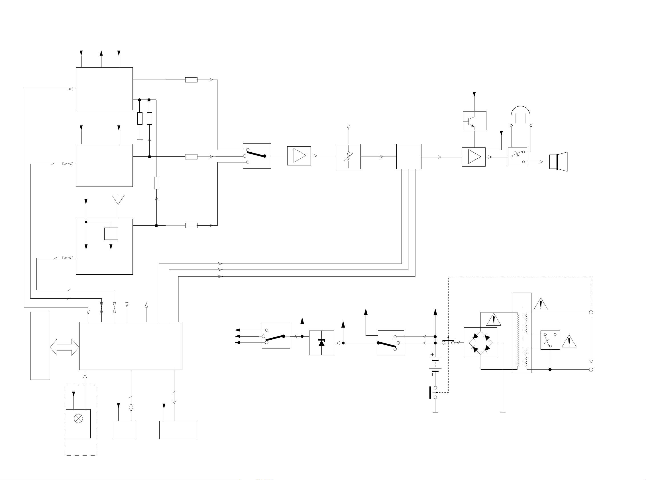
SOURCE
SELECTOR
SWITCH
4 OHM
~
~
CD - 99
LCD
CD MODULE
Head
phone
(AZ1505
ONLY)
+
-
+A-ON
Tuner
+CD
TAPE MUTE
CD MUTE
SEARCH MUTE
MICRO
PROCESSOR
To Tuner
+Tuner
To CD
REC INFO
+B
+µp
+µp
EEPROM
TAPE
CD
ECO6
TUNER MODULE
+Tuner
Keys
board control
IR
receiver
+A_ON
POWER
AMPLIFIER
+A
Voltage Selector
/01/11 Only
Mains
TAPE MODULE
+TAPE +A+1
Transformer
PWM
2
2
MUTE
5
To µp
5
5
To µp
5
REC INFO
R
R
R
R
R
R
V.M.
Vcc2
6X1.5V
+CD
REGULATOR
VOLTAGE
+TUNER
+A
+motor
+A_ON
+B
+TAPE
POWER
AMPLIFIER
POWER
AMPLIFIER
PWM
BLOCK DIAGRAM
5 - 25 - 2
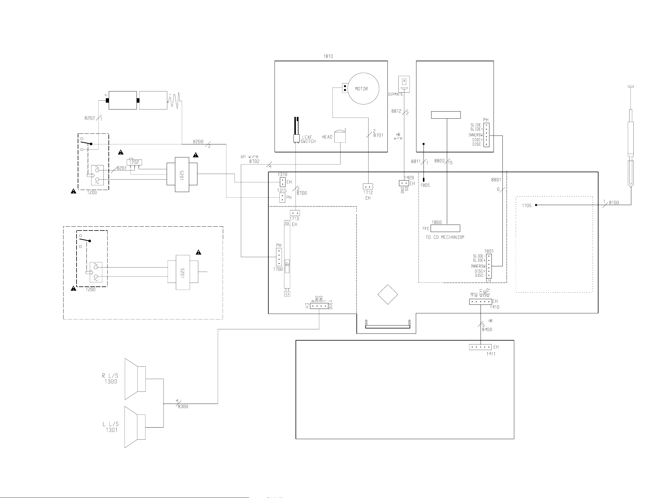
MECHANISM
MAINS SOCKET
FOR
SECONDARY
TRANSFORMER
15
1
CD DOOR
COMBI BOARD
LCD
BATTERIES
1
/00,/05,/10,
ORANGE
15
ECO-MTF
FOR /01
SWITCH
TAPE MECHANISM
LAYOUT
VOLTAGE SELECTOR
110-127V
220-240V
BLUE
9V BATTERY
TRANSFORMER
BLACK
6
CD
CPU
/13,/14,/17
1
SECONDARY
CELL
1
CD99
LAYOUT CELL
MAINS SOCKET
TUNER
LAYOUT CELL
ECO6
FRONT BOARD
WIRING DIAGRAM
 Loading...