

Philips AZ1050 Service Manual
CD Stereo Radio Recorder
AZ1050
AZ1055
all versions
TABLE OF CONTENTS
chapter
Handling chip components and safety 1 - 1
Technical Specification & Service Tools 2 - 1
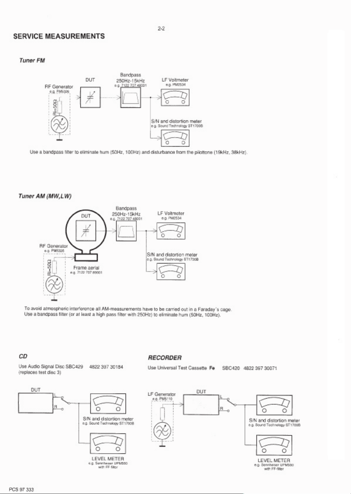
Service Measurement 2 - 2
Connections & Controls
Instructions for use
Disassembly Diagram 4 - 1
CD Service Test Program 4 - 2 to 4 - 3
Block Diagram
Wiring Diagram 5 - 2
TUNER BOARD
circuit diagram
layout diagram
COMBI BOARD
circuit diagram
layout diagram
..................................................
................................................
.................................................
...................................................
........................................
.............................................................
...........................................................
.......................................................
.......................................................
...............................................
....................................................
.............................
..........................
3 - 1
3 - 2 to 3 - 5
5 - 1
6 - 1
6 - 2
7 - 1, 7 - 3, 7 - 5
7 - 2, 7 - 6
FRONT BOARD
circuit diagram
layout diagram
EXPLODED VIEWS DIAGRAM
cabinet
tape deck
Mechanical partslist
Electrical partslist
.......................................................
.......................................................
.................................................................
............................................................
.....................................................
...............................................
chapter
7 - 4
7 - 4
8 - 1
8 - 2
8 - 2
9 - 1 to 9 - 4
Safety regulations require that the set be restored to its original
condition and that parts which are identical with those specified
be used.
C
Copyright 1995 Philips Consumer Electroncis B.V. Eindhoven, The Netherlands
All rights reserved. No part of this publication may be reproduced, stored in a retrieval
system or transmitted, in any form or by any means, electronic, mechanical, photocopying,
or otherwise without the prior permission of Philips.
Printed in The Netherlands Copyright reserved Subject to modification
PCS 107 205
CLASS 1
LASER PRODUCT
GB
3140 785 22620Published by SS 0105 Service Audio

TECHNICAL SPECIFICATIONS
2-1
GENERAL
Mains voltage
Mains frequency-/00/05/10/14 : 50 Hz
Battery mains : 9 V (R20 x 6)
Power consumption : 5 W
Dimension (W x H x D) : 435 x 252 x 170 mm
Weight : 3.4 Kg
-/00/05/10/14
-/01/11 : 120 / 230 V
-/01/11 : 50 / 60 Hz
Remote : 3V (R6 x 2)
: 230 V
-/17 : 120 V
-/17 : 60 Hz
AMPLIFIER
Output power mains : 2 x 1.4 W
battery : 2 x 1.6 W
Speaker impedance : 2 x 4 ohm
Frequency response : 100 Hz - 10 kHz (±3dB)
TUNER - FM SECTION
Tuning range : 87.5 - 108 MHz
IF frequency : 10.7 MHz ± 0.2 MHz
Sensitivity : 14 dBf at 26dB S/N
Selectivity : 45 dB at 300kHz
IF rejection : 65 dB
Image rejection : 26 dB
TUNER - AM SECTION
Tuning range MW : 522 - 1607 kHz
-/17 : 520 - 1730 kHz
IF frequency : 468 kHz ± 3 kHz
Sensitivity MW : 1500 µV/m at 26dB S/N
Selectivity MW : 20 dB
IF rejection MW : 60 dB
Image rejection MW : 32 dB
AUDIO CASSETTE RECORDER
Number of tracks : 2 stereo
Tape speed : 4.76 cm/sec ± 3%
Wow & flutter : < 0.48 JIS UWTD
Fast wind/rewind C60 : < 120 sec.
Frequency response P/B : 125 - 8000 Hz
S/N ratio :
≥ 40 dB
COMPACT DISC
Frequency response : 100 Hz - 10 kHz
S/N ratio : 60 dB
Channel difference 1 kHz : < 3 dB
Channel crosstalk 1 kHz : 40 dB
Laser wavelength : 780 ± 20 nm
Laser light power : < 0.5 mW
SERVICE TOOLS
TORX T10 screwdriver with shaftlength 150mm.........................................4822 395 50423
TORX screwdriver set SBC 163...............................................................4822 295 50145
Audio signal disc SBC 429........
Playability test disc SBC 444...................................................................4822 397 30245
Test disc 5 (disc without errors ) +
Test disc 5A (disc with dropout errors, black spots and fingerprints)
SBC 426/426A.....................................................................4822 397 30096
Burn in test disc (65 min. 1kHz signal at -30 dB level without “pause”)
Universal test cassette Fe SBC 420
..............................................................4822 397 30184
.....4822 397 30155
........................................................4822 397 30071
PCS 107 206
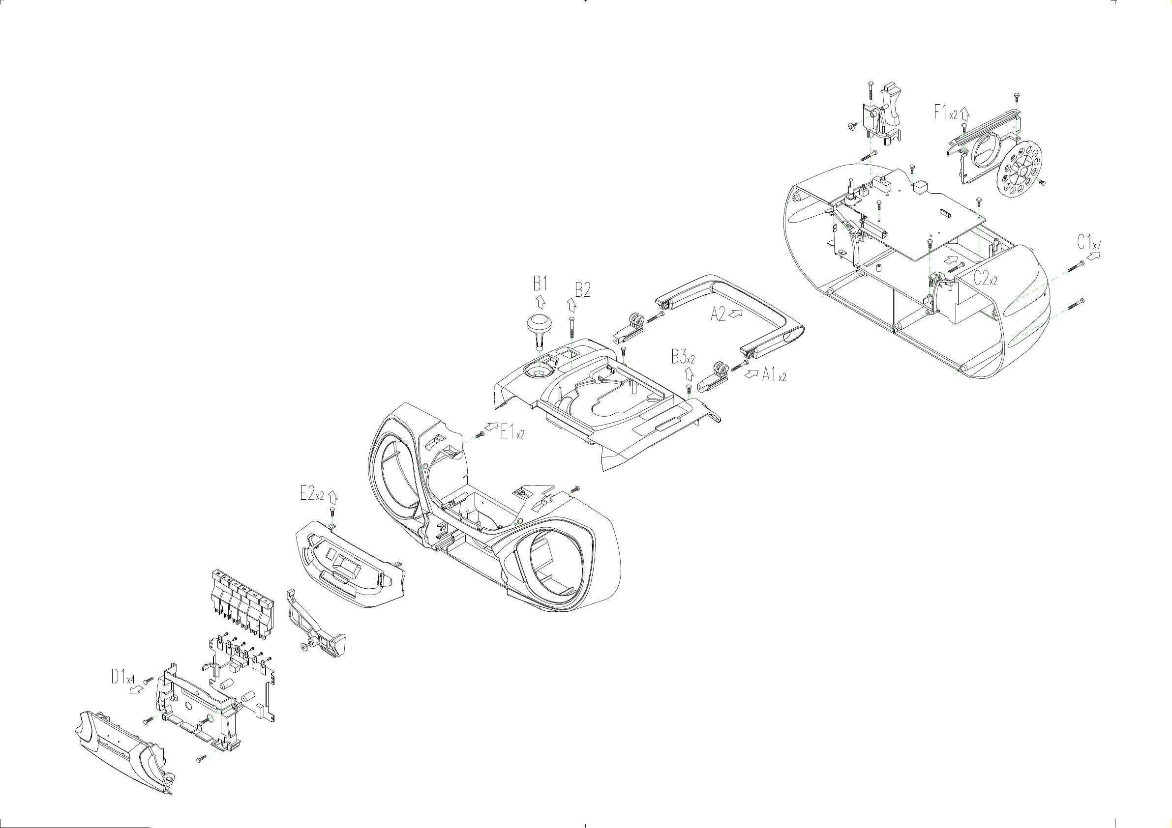
DISASSEMBLY DIAGRAM
A. To remove Handle
B. To remove Top Panel
C. To remove Front Cabinet Assy
D. To remove Tape Deck
E. To remove Front Panel
F. To remove Tuner Board
4-1 4-1
PCS 104 241
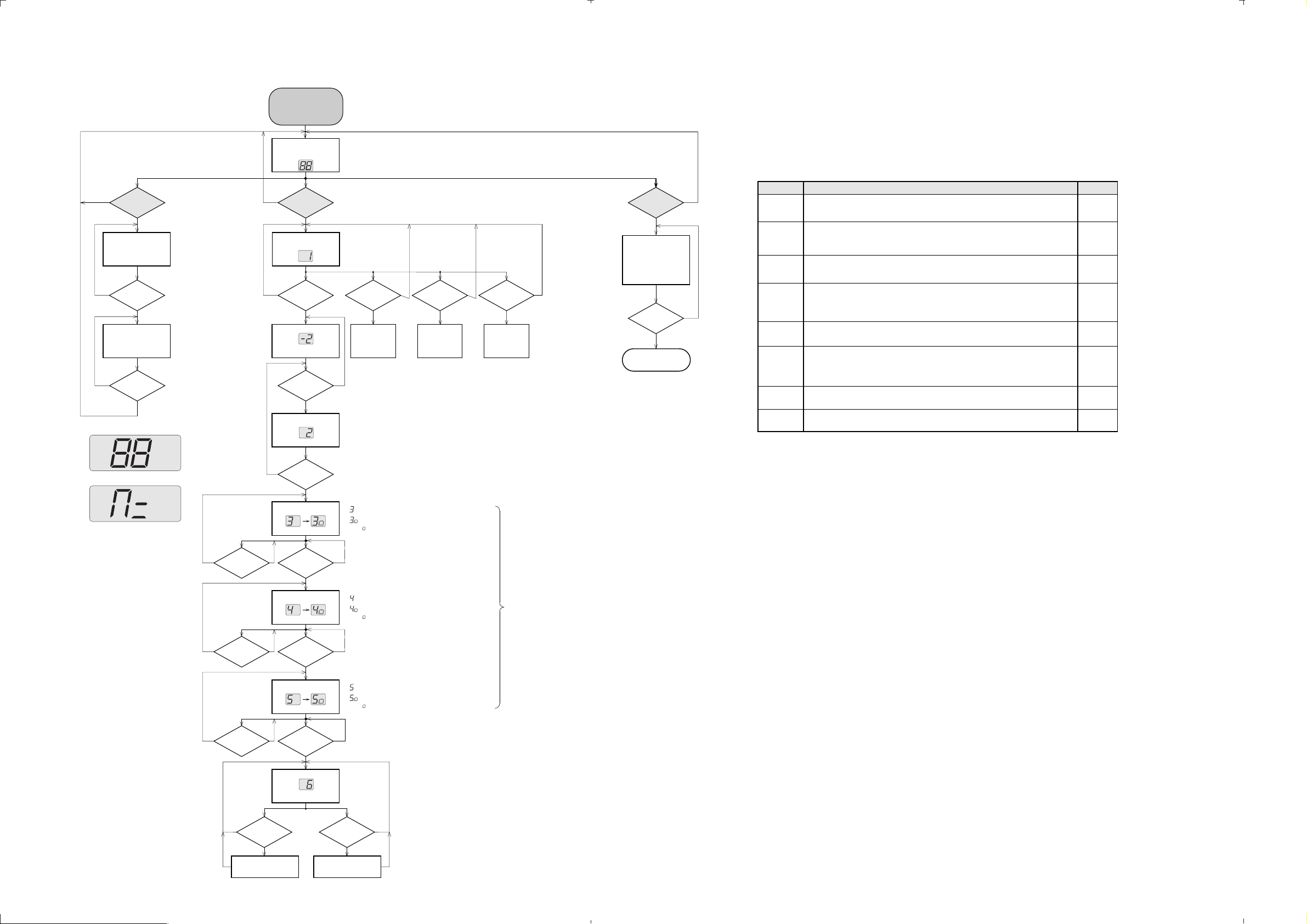
SERVICE TESTPROGRAM
4-2 4-2
NEXT button
N
pressed?
Display shows all
segments and flags
for checking open circuits.
see figure 1
N
NEXT button
pressed?
Display shows figure 2.
All alternate pins (2, 4, ..)
of the display are activated
for checking shortcircuits.
STOP button
N
pressed?
REPEAT
ALL
fig. 1
fig. 2
To enter Service
Testprogram hold
PLAY & STOP buttons
depressed while switching
CD mode on.
Display shows
version number
of the µP - software.
Slide servo, Radial servo, Focus servo, Disc motor
and Laser are switched off.
Mute is switched on via decoder IC.
DISPLAY TEST CD SERVO TEST
Y
Y
Y
SHUFFLE
PROGRAM
SHUFFLEREPEAT
FOCUS search
automatic
adjustment of
TRACK BALANCE
PLAY button
N
pressed?
Display shows
N N N N
PLAY button
pressed?
Display shows
objective moves up&down
disc motor for 160ms "on"
FOCUS found?
Display shows
disc motor turns.
N
PLAY button
pressed?
Display shows
STOP button pressed in any step returns
to begin of Service Testprogram.
Y
Y
N
Y
Y
To leave Service Testprogram switch
*
CD mode off.
Door switch is ignored Æ CD door can be opened.
*
SLIDE test DISC MOTOR test
NEXT button
pressed?
Y Y Y
Slide moves
outside as long as
button is hold
depressed.
To check Focus over the whole disc area
Slide - and Discmotor can also be activated
in FOCUS - test.
PREV. button
pressed?
Slide moves inside
as long as button
is hold depressed
or until
inner-switch
is activated.
while autom. track balance adjustment is active
as soon as track balance adjustment finished.
(1 - 6) indicates the actual setting.
MODE button
pressed?
Disc motor turns
clockwise
as long as button
is hold depressed.
(accelerate )
CD PLAY TEST
1)
The CD PLAY TEST is intended to be used
for continuously playing a disc in order to
detect intermittend or not reproducible
failures. The error code indicates where
the failure can be found.
1)
MODE button
pressed?
Y
CD is in normal
PLAY mode.
In case of failures
error codes acc. table 1
will be indicated
on the display.
POWER
switched off?
Y
Exit Service Testprogram
N
N
CD ERROR codes
Error number Error type
E0 Focus Error
Triggered when the focus is lost for more than 250ms during playing the CD.
E2 Slide-in error
Generated when the inner-switch did not close within approx. 4s when the pick up is
moved inside. Inner-switch or slide motor problems.
E3 Slide-out error
Generated when the inner-switch did not open within approx. 250ms when the pick up is
moved from the inner position outside. Inner-switch or slide motor problems.
E5 Jump error.
Triggered when the servo processor counts too less tracks in a defined time during JUMPS.
This can be caused by a disturbed HF-signal (the tracks cannot be recognized exactly),
slide motor problems, track servo problems or scratched discs.
E6 Subcode Error
No valid subcode for 300ms during PLAY.
E7 PLL lock error
When the PLL did not lock after 10 retries then this warning message is generated and
the servo is stopped and restarted (as if the user would have pressed STOP and then
PLAY immediately) to recover.
F0 Focus Search Error
Triggered when the focus could not be found within 3s when starting up the CD.
F2 Fatal Subcode Error
No valid subcode for more than 4s during PLAY.
Error type:
W = Warning Æ
F = Fatal Error
set continues operation, message remains on the display until next error occurs
or any key is pressed.
Æ set stops operation, message remains on the display.
(The set can only be operated again via a reset)
Error description
W
W
W
W
W
W
F
F
table 1
servtest EVA, 030398
Y
MODE button
pressed?
automatic
adjustment of
FOCUS GAIN
Y
MODE button
pressed?
automatic
adjustment of
TRACK GAIN
Y
MODE button
pressed?
RADIAL test
NEXT button
pressed?
CUE - mode
jumps in steps of
16 tracks forward
N
PLAY button
pressed?
Display shows
N
PLAY button
pressed?
Display shows
track servo switched on
N
PLAY button
pressed?
Display shows
Æ Play mode
MUTE is switched off
Y
N
Y
N
Y
N
Y
PREV button
pressed?
REVIEW - mode
jumps in steps of
16 tracks backwards
while autom. focus gain adjustment is active
as soon as focus gain adjustment finished.
(1 - 6) indicates the actual setting.
while autom. track gain adjustment is active
as soon as track gain adjustment finished.
(1 - 6) indicates the actual setting.
Purpose of RADIAL test:
To check if the Audio signal is reproduced.
Subcode info is ignored during this test Æ
If the CD player functions well in this testmode,
but not in the normal Play mode check quality
of the eye-pattern signal.
NN
Y
If the margin settings 0 or 7 are displayed the required
setting is possibly out of the adjustment range.
Æ check disc drive and/or electronic circuitry
PCS 99 154

mp Æ
mp Æ
mp Æ
mp Æ
Æ
mp Æ
mp Æ
m
mp ´
m
mp Æ
m
Æ
Æ
Æ
Æ
Æ
Æ
CD STARTUP PROCEDURE
BEGIN
+A(CD)
supplied to
CD part?
Decoder delivers CLOCK -
frequ. 4.23MHz to µP.
µP-RESET line Æ high
µP init. Decoder 7801.
Init. 7801 for ext. DAC Init. 7801 for int. DAC
µP moves slide inside
µP moves slide outside
(0,2s time-out starts)
Disc motor 100ms on
µP initializes Decoder
and Servo IC:
-start turntable
-adj. track bal. and gain
-read subcode (TOC)
Y
Level on
pin23
(CD-RESET)
after 100µs?
(4s time-out starts)
inner switch
closed?
Y Y
inner switch open?
Y Y
slide off
Door closed?
Y
Laser on
FOCUS search on
focus found? 3s time-out over?
Y
TOC
found?
Y
display shows
max. trackno.
STOP MODE STARTUP FAILED
CD switched on
(mode switch)
N
HIGHLOW
N
4s time-out over?
N
0,2s time-out over?
Display shows
N
N
N
N
N
N
4-3 4-3
Abbreviations and Pin-descriptions of CD ICs
SERVO PROCESSOR M62475FP
Remark: To check focus servo, slide servo, track servo and turntable
use service test program
- Battery empty?
- check +A,
- mode switch o.k.?
check: - +A(CD), +B(CD), +LASER, +M,
- time constant of reset circuit
- Pin 32 of µP 7800 HIGH ?
- Pin 30 of µP 7800, if 4.23 MHz o.k.
check: - door switch
Y
startup proc.
stopped,
display shows
check: - Laser light on ?
Check pin 38 of 7803 and LASER CONTROL circuit
- Focus Servo
check: - Motor control pin 27 of Decoder 7801 and
Disc Motor driver 7805
- HF Signal by using service testprogram
CDstartup EVA, 080997
Pin Name Direction Description
1-3
A, B, C
4-5
E, F
6 SGT
7 TE - - Inverting input of track error amplifier
8 TEGain - Gain control pin of track error amplifier
9 TG1 - Track Gain 1 - switch: controls the gain of the track servo amplifier
10 TE out - Track Error amplifier output
11 TC/Shock - Track Cross/Shock detector input
12 TS + - Non inverting input of track servo amplifier
13 TG2 not connected Track Gain 2 - switch: controls the gain of the track servo amplifier
14 TS - - Inverting input of side servo amplifier
15 TS out
16 SS + - Non inverting input of slide servo amplifier
17 SS - - Inverting input of slide servo amplifier
18 Slide out
19 DET. FILTER 20 BIAS
21 GND - Ground connection pin (negative supply)
22 MLA/DIS
23 JP1/SG
24 MCK
25 MSD
26 D
out
27 C
LPF
28 I
REF
29 V
CC
30 FS
OUT
31 FS - - Inverting input of focus serco amplifier
32 FEGain - Gain control pin of focus error amplifier
33 FE - - Inverting input of focus error amplifier
34 SGF
35 C
FSR
36 ALPC + - Non inverting input of Automatic Laser Power amplifier
37 ALPC - - Inverting input of Automatic Laser Power Control amplifier
38 ALPC
39 MRC - Connection pin for capacitor of Mirror detector
OUT
40 HF
41 HFI - Inverting input of HF amplifier
42 ABC - Sum output of amplified A, B and C input (central photo diode signal input)
SERVO PROCESSOR M65824FP
Pin Name Direction Description
1 Anal. V
2 ADJCLK not connected Clock output for servo adjustment; f=88.2kHz
3 LOCK not connected Lock monitor / low disc rotation output
4 CKSEL - System clock selection. Low=8.4672MHz, high=16.9344MHz
5 RESET
6 C423
7 C846 not connected 8.4672MHz clock output
8 XI
9 DVSS - Digital system ground
10 XO
11 TEST - Normal / Test selection input. Testmode = high
12 SBCO not connected Subcode serial output
13 SCCK - Shift clock input for subcode data read
14 SYCLK not connected Frame lock status output. Lock = high
15 EFFK not connected EFM frame clock output. Duty = 50%
16 KILLB not connected Digital silence mute output. Digital zero = low
17 EST1 not connected Error monitor output 1
18 EST2 not connected Error monitor output 2
19 HF
20 TLC - Slice level control signal output
21 LPF - PLL loop filter
22
23 DSPS - Digital system power supply
24 SBQS not connected Interrupt signal to read out subcode Q data. Read = low
25 CRCF not connected Subcode Q-channel Cyclic Redundance Check Flag output. CRC o.k. = high level
26 SCAND not connected Subcode sync signal detection. Sync = high
27 PWM
28 DVDD2 - Digital interface power supply 2
29 DVSS2 - Digital system ground 2
30 MCK
31 MSD
32 MLAB
33 EXP1
34 EXP2
35 CGREF
36 AMPREF not connected Op-amp for LPF reference voltage setting
37 LOUT/DO
38 LNEG not connected Charge pump output (left channel) / Ext.DAC mode: Wordclock output
39 ROUT/DSCK
40 RNEG/LRCK
41 IREF - Current reference
42 Anal. V
Dig. V
SS
DD
DD
Diode array Æ Servo processor
Diode array Æ Servo processor
Servo processor Æ Track error ampl. Input
Servo processor Æ Servo driver
Servo processor Æ Motor driver
Servo processor Æ external electronic
Servo processor
Servo processor
Servo processor
Servo processor
Servo processor Æ mp
-
- Reference current input
- Positive supply connection pin (4V - 5.5V)
Servo processor Æ Servo driver
Servo processor
Focus error ampl. Input
- Charge capacitor for Focus Search triangle-generator
Servo processor Æ Laser driver
Servo processor Æ Decoder
- Analog system ground
Signal processor
Signal processor Æ mp
X-Tal Æ Signal processor
Signal processor Æ X-Tal
Servo processor Æ Signal processor
- Digital interface power supply
Signal processor Æ Motor driver
Signal processor
Signal processor
Signal processor
Signal processor
Signal processor
Signal processor
Signal processor
Signal processor
Signal processor
- Analog system power supply
Current input (central photo diode signal input)
Current input (satellite photo diode signal input)
Signal generator output to track servo, sends 1700Hz for adjustment procedure
Output of track servo amplifier
Output of slide servo amplifier
Pin for connection of DETection FILter capacitor of ADJUST LOGIC
Reference Voltage output Vcc/2 of internal BIAS-generator
Serial interface Microprocessor Latch control/DIScharge control for adjustment
Serial interface Jump control line/Signal Generator input line for adjustment
Serial interface Clock input line
Serial interface Data input line
Serial interface Data output line
Pin for connection of Low Pass Filter capacitor of ADJUST LOGIC
Output of focus servo amplifier
Signal generator output to focus servo, sends 1300Hz for adjustment procedure
Output of Automatic Laser Power Control amplifier
Output of HF amplifier
to external ac-coupling capacitor
System reset (low level = active)
4.2336MHz clock output
Crystal oscillator input
Crystal oscillator output
HF signal input
Disc motor driving (Pluse Width Modulation) output
p interface shift Clock input
p interface Serial Data I/O line
p interface Latch clock input (internal 22k pull up resistor)
Versatile input pin (internal 4.7k pull up resistor)
Versatile input pin (internal 4.7k pull up resistor)
Charge-pump for LPF reference current input
Audio signal output (left channel) / Ext. DAC mode: Audio serial data output
Audio signal output (right channel) / Ext. DAC mode: Data shift clock output
Charge pump output (right channel) / Ext.DAC mode: L/R clock output
PCS 99 155
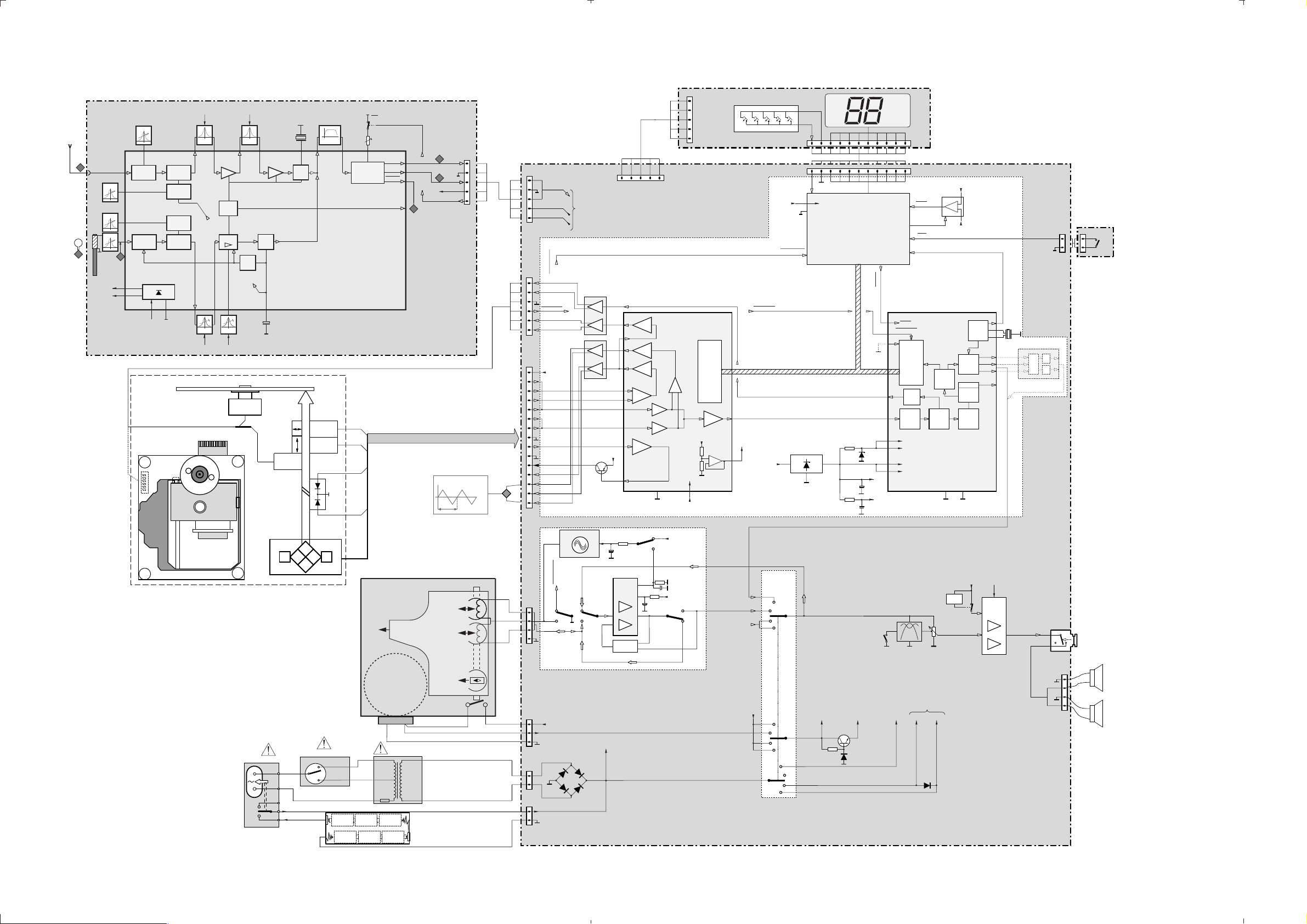
BLOCK DIAGRAM
5-1 5-1
TELESCOPIC
ANTENNA
TUNER BOARD
A
FM-Osc.
AM-Osc.
FERRITE
ANTENNA
AM-RF
B
V
A
Stab
V
B
Stab
ext. DAC
only
+Laser
+M
1350
DBB
SHUFFLE
PROGRAM
23
CD-reset
5
Inner Switch
33
34
27
PWM
HF
19
42
23
22
28
+A(CD)
1820
X
reset
frontend
1814
11
11
1812
32
watchdog
13
27
30
in
DATA INTERFACE
motor
control
PLL
VDD analog
VDD logic
VDD 1
VDD 2
reset
door
VOLUME
to 1201
RESET
7801
DECODER
M65824
audio
processor
digital
PLL
1 29
3300
+B(CD)
+
-
4.23MHz
soft
on/off
+M
Clock
Generator
l/r clk
left data
DAC
right
flags
error
control
EFM
demod.
POWER STAGE
+A(on)
TA8227P
on/off
10
40
37
39
18
7300
6
8
+A
5803
8.46MHz
L/R CLK
DSCK
left, right out
ext. DAC (opt.)
TDA1311A/N2
2
3
data
1
interface
EVA Blockdiagr., 160398
1809 1808
8
D/A
6
D/A
HEADPHONE
1302
1301
-
LEFT
+
-
RIGHT
+
2
2
1807
door
1
switch
1
p
-
4
1
Left
4Ω
+
Right
4Ω
+
1900
5
V
A V
Stab
FM
FM
Osc.
AM
Osc.
AM
FM-IF 1 FM-IF 2
10,7 MHz 10,7 MHz
AM/FM
Indicat.
AFC
1514 10 20
AM-IF 1 AM-IF 2
FM-RF
16
FM
frontend
Mixer
23
24
18
AM
Frontend
C
12
8
Mixer
STABILIZER
625
Vcc
V
A V
Stab
DISC
FLEX WIRE
a
t
n
b
r
Inner
switch
m
o
e
t
o
d
i
r
l
s
l
u
e
t
pick up
unit
CD-drive
CD 97 DA11
CD94V5T1
B
Stab
Discr.
LF filter
FM
Det.
285 29
9 27
7111321
AM
Det.
IF2
IF1
AM IF
AGC
AFC
AGC/AFC
468kHz468kHz
B
Stab
DISC
MOTOR
TRACK
SERVO
FOCUS
SERVO
C
C
C
DAB
DAB
DAB
(for /01/11 only)
1007
Laser
diode
Monitor
diode
F
F
F
VOLTAGE
SELECTOR
PHOTO DIODE
ARRAY
1006
MAINS-SOCKET
1
2
SLIDE
SERVO
E
5
4
3
+
AM/FM
switch
7102
VCO
left
Stereo
right
Decoder
stereo
tuning indicator
7101
RADIO IC
TEA 5711T
Th. 115˚C
BATTERY COMPARTMENT
(R20)
6 x 1.5V
3
5V
0V
stereo stereomono
2
left
1
right
+A
Vcc
+A
152kHz, 50mV
FLEX WIRE
Focus search
Service step 2
0.3s
2
3
30
26
TAPE TRANSPORT
right
PLAY
permanent
magnet
erase head
MOTOR
+-
5001
(Tuner)
(FM)
pp
left
on /off
1101
5
1
N S
1
COMBI BOARD
1201
5
Tuner L
Tuner R
+A
(Tuner)
+A
(FM)
1
1810
1
Disc Disc +
Inner Switch Inner Switch
Slide +
Slide -
6
1811
15
+Laser
E
F
B+D
A+C
Monitor
Laser
Track Focus +
1601
1204
1202
1203
1
1
4
3
1
1
2
2
1
Track +
Focus -
+A
+A (TAPE)
6250
6251 6252
+Battery
+
2V
-
CD Synchro
Bias Oscillator
CD Synchro
Rec
Pb
Rec
4x 1N4002
to/from
source switch
MOTOR DRIVER
SERVO DRIVER
Rec
Pb
Pb
Rec
6253
!
1
1901
CD - PART
PWM
DISC
18
SLIDE
FOCUS
TRACK
+Laser
7854
REC/PB - AMPLIFIER
16261626
+A
16
30
15
4
5
1
2
36
28
7625
Rec/Pb
Amplifier
AN7318S
Feedback
SLIDE
FOCUS
TRACK
+
E - F
-
ALPC
1626
Rec
5
7803
SERVO PROCESSOR
M62475
A+B+C+D
Vcc
21 29
+B(CD)
Rec
+B (TAPE)
Pb
ALC
+B (TAPE)
Pb
1626
Rec
Rec
KEY
+B (CD)
GND
RC5
RC5'
Vcc
SERIAL DATA INTERFACE
-
+
FRONT BOARD
MODE
PREV
NEXT
40
HF
HF
REF
20
CD
Tuner
PLAY
CD Synchro
DISC MOTOR
4V
PWM
eye-pattern
+A(CD)
SOURCE
SWITCH
1250
CD
Tape
Pb
FM
AM
+A
CD
Tape
FM
AM
STOP
1
1
key in
12 1, 35-40
39
+M
16
8
TB 2us/Div
TB=0,5 us/DIV
Rec
CD
Tape
FM
AM
REPEAT
ALL
VDD
VSS
+A(on) +B(Tape) +A(FM) +A(Tuner)
MICRO PROCESSOR
TMP47C422F
+B(CD)
7800
PCS 104 242
 Loading...