

PHILIPS AZ1009 Service Manual

Published by MS 9741 Service Audio Printed in The Netherlands Subject to modification
chapter
Technical Specification................................................2-1
Measurement setup.....................................................2-2
Controls & Connections...............................................2-3
Brief Operating Instructions....................................2-4 to 2-7
Warnings & Safety.......................................................2-8
Dismantling Instructions..........................................3-1 to 3-3
Service hints...........................................................3-4 to 3-6
CD - startup procedure ................................................3-7
Abbreviations CD-ICs ..................................................3-8
Service Test Program.................................................3-10
BLOCK DIAGRAM.......................................................4-1
WIRING DIAGRAM......................................................5-1
TUNER BOARD
schematic diagram ..................................................6-1
component layout....................................................6-2
adjustment table......................................................6-2
chapter
FRONT BOARD
component layout .................................................7-1
schematic diagram .................................................7-2
COMBI BOARD
component layout ................................................7-1, 7-4
schematic diagram CD part.....................................7-2
Recorder/Amplifier part............7-3
EXPLODED VIEWS
apparatus, drawing 1...............................................8-1
apparatus, drawing 2...............................................8-2
tape transport ..........................................................8-3
MECHANICAL PARTSLIST see Exploded views
ELECTRICAL PARTSLIST.........................................9-1 ff
TABLE OF CONTENTS
CS 49 101
AZ1009/00/05/17
© 4822 725 26015
CD Stereo Radio Recorder
CLASS 1
LASER PRODUCT
AZ1010/00/01/04/05/10
/11/11H/14/17
©
Copyright 1997 Philips Consumer Electronics B.V. Eindhoven, The Netherlands
All rights reserved. No part of this publication may be reproduced, stored in a retrieval
system or transmitted, in any form or by any means, electronic, mechanical, photocopying,
or otherwise without the prior permission of Philips.
Service Manual
xystus
DB
D
B
B
DYNAMIC
B
DYNAMIC
BASS
BASS
BOOST
BOOST
CD SYNCHRO START RECORDING
CD SYNCHRO START RECORDING
VO
VO
LUM
LUME
E
PAUSE
PAUSE
STOP.OP
STOP.O
EN
PEN
BASS REFLEX SPEAKER SYSTEM
BASS REFLEX SPEAKER SYSTEM
OPEN
OPEN
S
EA
S
E
R
A
C
R
H
C
H
PLAY
PLAY
R
EC
R
O
E
R
C
D
O
R
D
CD MODE
CD MODE
FM AM
FM AM
10
8
1
0
17
8
00
1
70
1
04
0
10
4
13
0
13
0
0
104
0
1
04
10
00
10
0
0
9
0
9
8
0
00
80
0
9
2
92
630
6
30
TU
TUN
N
IN
G
IN
8
8
G
88
53
0
5
3
0

TECHNICAL SPECIFICATION
General:
Mains voltage : 220V-230V / 50Hz for /00 /04 /14
230V-240V / 50Hz for /05 /10
110V-127V / 220V-240V /50Hz switchable for /01 /11 /11H
120V / 60Hz for /17
Battery : 9V ( 6xR20 )
Power consumption : ≤ 15W at maximum output power, ( ≤ 11W at 1/8 P
max
)
≤ 5W (typ. 2W) with source switch in
tape/off
Amplifier:
Power stage protection : temperature and shortcircuit
Output power mains : 2 x 1,4Wrms -1dB at 4Ω D=10%
battery : 2 x 2Wrms -1dB at 4Ω D=10%
Headphone : 3,5mm stereo jack, ≥ 20mW at 32Ω (≡ 0,8V at 32Ω ) D=10%
Frequency response : 30Hz - 16kHz ( typ. at volume set to -20dB, CD mode 0dB signal level ⇒use SBC429 )
Tone control DBB : +12dB ±3dB at 100Hz ( volume set to -20dB )
Tuner:
FM MW
Tuning range 87,5 - 108 MHz 522 - 1607 kHz
(520 - 1730 kHz for /17)
IF 10,7 MHz ± 20 kHz 468 kHz ± 3 kHz
Sensitivity Mono: 26dB S/N, m=30% ≤ 4 µV ( ≤ 2µV typ.) ≤ 4mV/m (≤ 1,5mV/m typ.)
-3 dB limiting point ≤ 5 µV ( ≤ 2µV typ.)
AFC capture range ±300kHz typ.
Distortion ≤ 7% (≤ 1% typ.) ≤ 7% (≤ 2,5% typ.)
RF=1mV ∆f=75kHz RF=100mV/m m=80%
Image rejection ratio ≥ 20dB (26dB typ.) ≥ 28dB
Channel separation at 1kHz ≥ 20dB (25dB typ.)
CD:
To be measured on phone socket with 100kΩ load.
Frequency response : 30 - 16.000 Hz -4dB
Signal/Noise ratio : ≥ 60dB
Distortion : 0.2% typ. at 1 kHz
Channel difference : ≤ 3dB at 1 kHz
Channel crosstalk : 40dB typ.
De emphasis : 0 or 15/50µs switched automatically by subcode on the disc
Laser
Output power : 500µW
Wave length : 780 ± 20 nm
Recorder:
To be measured on phone socket with 100kΩ load.
Tape speed : 4,76cm/s ±3%
Wow & Flutter : ≤ 0,5% weighted
Winding speed : 120s for C60 cassette
Erase / Bias system : permanent magnetic erase head / AC 65 ±5kHz
Distortion at 250 nWb/m : ≤ 7%
Signal/Noise ratio (FF weighted) : ≥ 40dB
(A - weighted) : ≥ 43dB
Channel difference at PB : ≤ 5dB
Channel difference overall : ≤ 5dB
Channel separation : ≥ 15dB at 1kHz
Track separation : ≥ 55dB at 1kHz
Frequency response IEC I
Pb : 125Hz - 8000Hz (within 8dB)
overall : 250Hz - 6300Hz (within 8dB)
note: set is not prepared to play or record
IEC II Chrome
cassettes!
2-1
CS 49 102
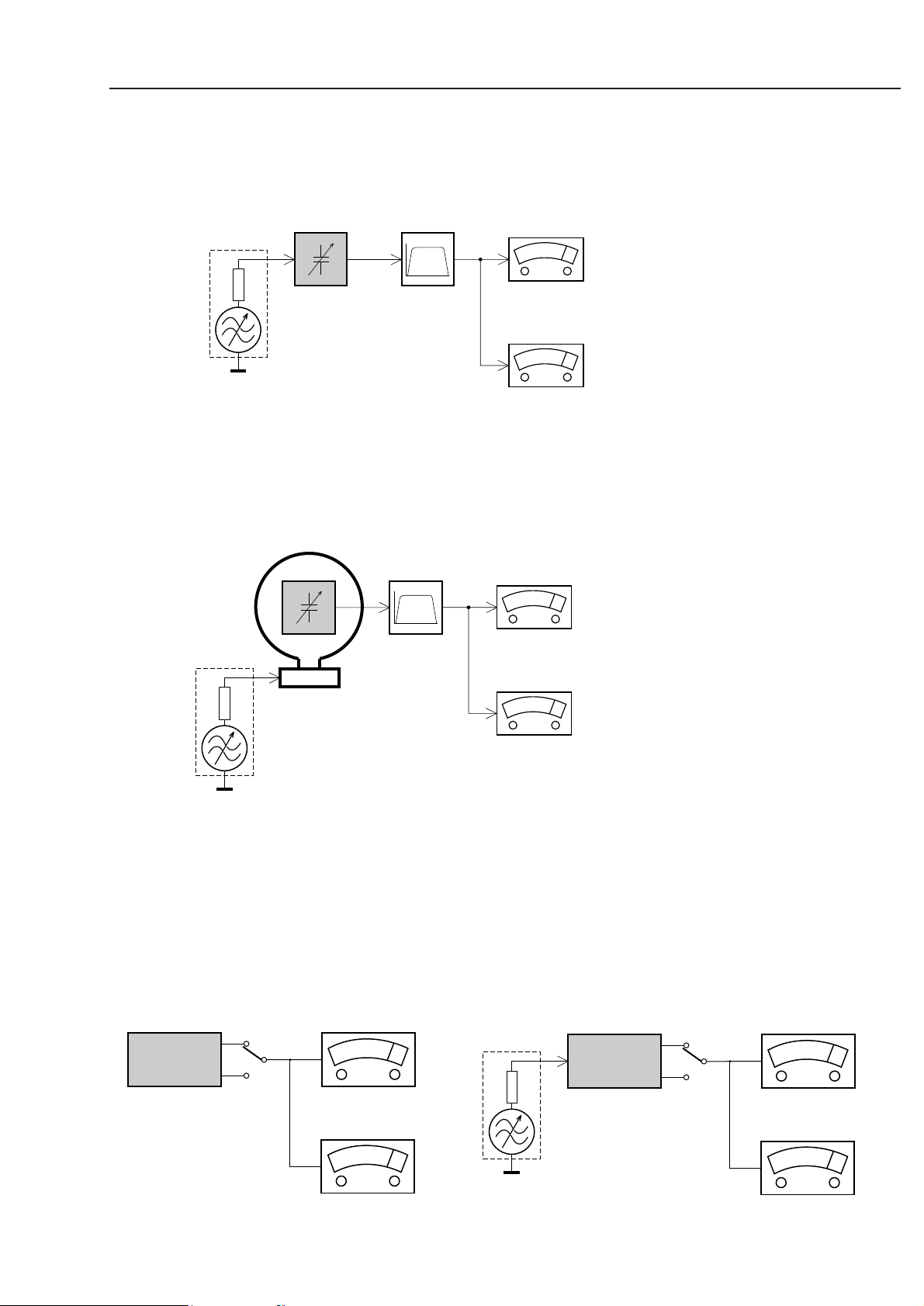
2-2
CS 49 103
Bandpass
250Hz-15kHz
e.g. 7122 707 48001
LF Voltmeter
e.g. PM2534
DUT
RF Generator
e.g. PM5326
S/N and distortion meter
e.g. Sound Technology ST1700B
Use a bandpass filter to eliminate hum (50Hz, 100Hz) and disturbance from the pilottone (19kHz, 38kHz).
Ri=50Ω
Tuner FM
Bandpass
250Hz-15kHz
e.g. 7122 707 48001
LF Voltmeter
e.g. PM2534
DUT
S/N and distortion meter
e.g. Sound Technology ST1700B
Frame aerial
e.g. 7122 707 89001
Tuner AM (MW,LW)
To avoid atmospheric interference all AM-measurements have to be carried out in a Faraday´s cage.
Use a bandpass filter (or at least a high pass filter with 250Hz) to eliminate hum (50Hz, 100Hz).
RF Generator
e.g. PM5326
Ri=50Ω
L
R
LEVEL METER
e.g. Sennheiser UPM550
with FF-filter
S/N and distortion meter
e.g. Sound Technology ST1700B
DUT
CD
Use Audio Signal Disc SBC429 4822 397 30184
(replaces test disc 3)
MEASUREMENT SETUP
L
R
LEVEL METER
e.g. Sennheiser UPM550
with FF-filter
S/N and distortion meter
e.g. Sound Technology ST1700B
DUT
RECORDER
Use Universal Test Cassette Fe SBC420 4822 397 30071
LF Generator
e.g. PM5110
2-3
CS 49 104
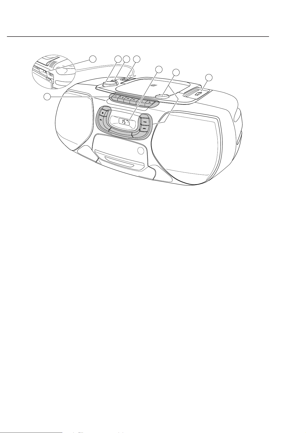
CONNECTIONS & CONTROLS
VOLUME
DBB
DYNAMIC
BASS
BOOST
CD S YN CH RO S TAR T RE CO RD IN G
PAUSE
STOP.OPEN
SEARCH
PLAY
RECORD
OPEN
FM AM
1700
1300
1000
800
630
530
TUNING
108
104
104
90
92
88
CD MODE
BASS REFLEX SPEAKER SYSTEM
4
7
8
5
6
1
3 2
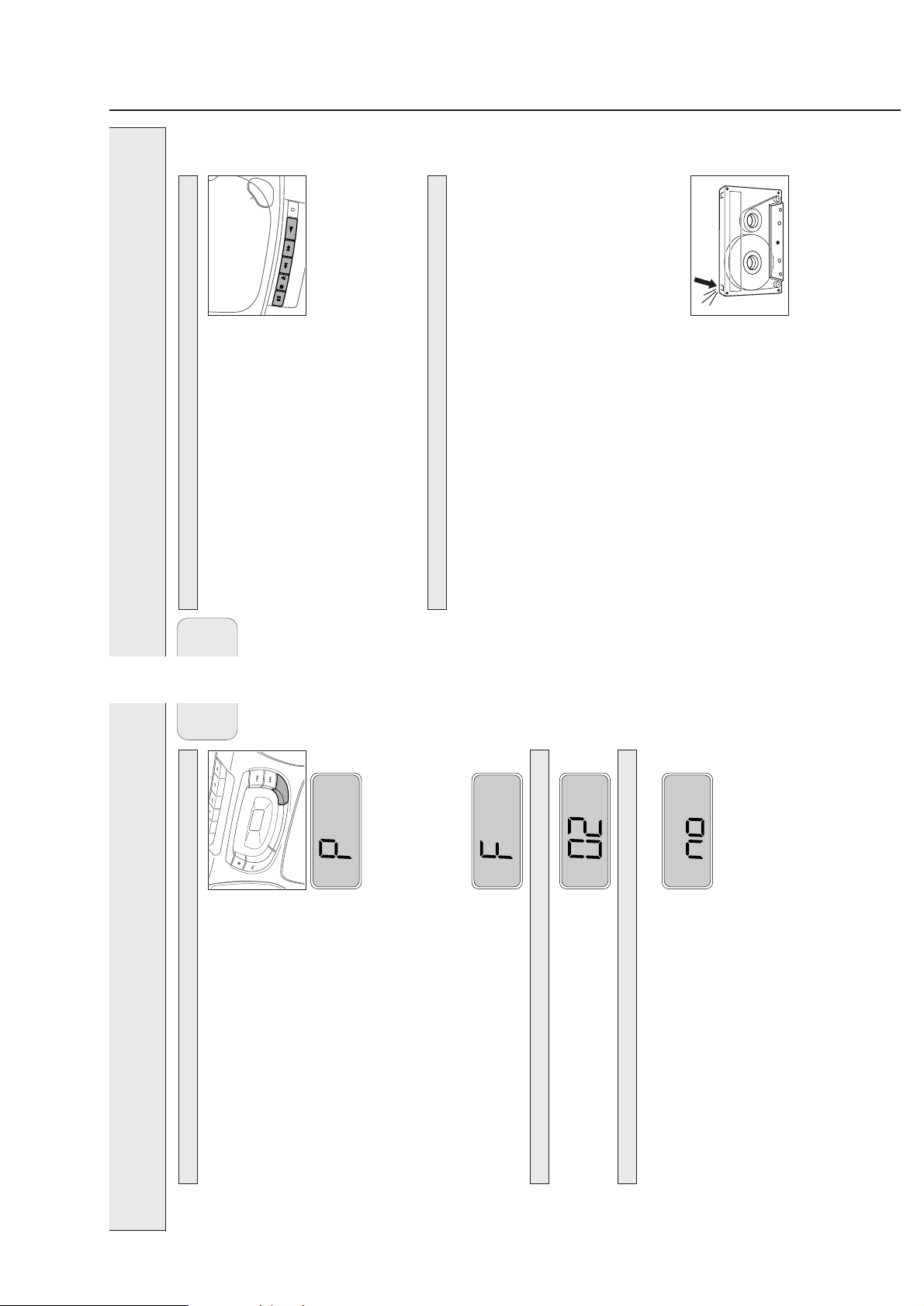
BASIC FUNCTIONS
1
POWER:
CD, TAPE, BAND
....selects the sound source
2 DBB.......................enhances the bass
3 VOLUME ...............adjusts the volume level
4
p...........................3.5mm headphone socket (back of the set)
Note: Connecting the headphones will switch off the speakers.
5 CASSETTE RECORDER
PAUSE
; ...............interrupts recording or playback
STOP·OPEN 9 / ..stops the tape and opens the cassette compartment
SEARCH 6...........rewinds the tape
SEARCH 5...........fast forwards the tape
PLAY 1 .................starts playback
RECORD 0............starts recording
RADIO
6 TUNING ................tunes to radio stations
1 BAND: FM, MW ...selects the wave band
7 CD PLAYER
/ OPEN ................opens the CD compartment
9...........................stops CD play and erases the program
2;.........................starts and interrupts CD play
§ .........................skips and searches forward
∞ .........................skips and searches backward
CD MODE..............selects the different CD playing modes and programs
tracks
8 Display
2-4
CS 49 105
A
R
R
INSTRUCTION FOR USE
FM
AM
BAND
DYNAMIC
POWER
DBB
CD
OFF
TAPE
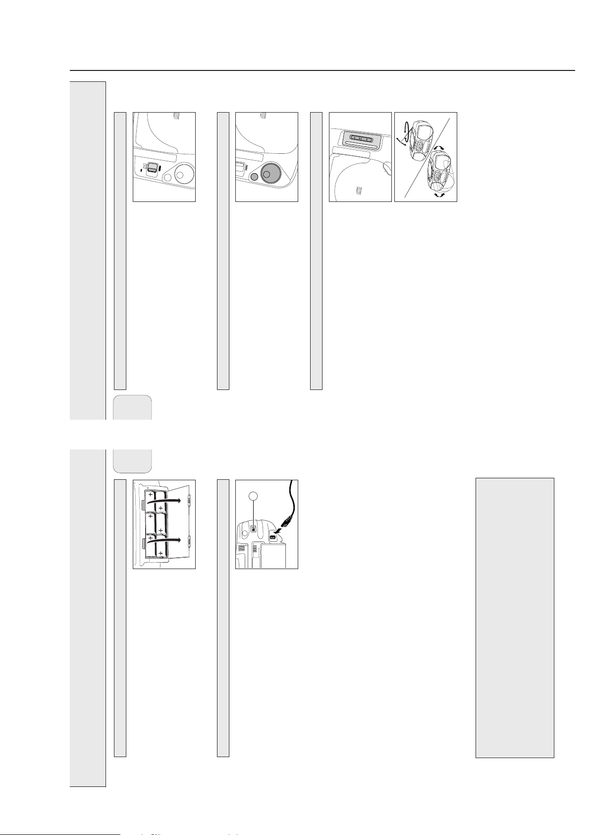
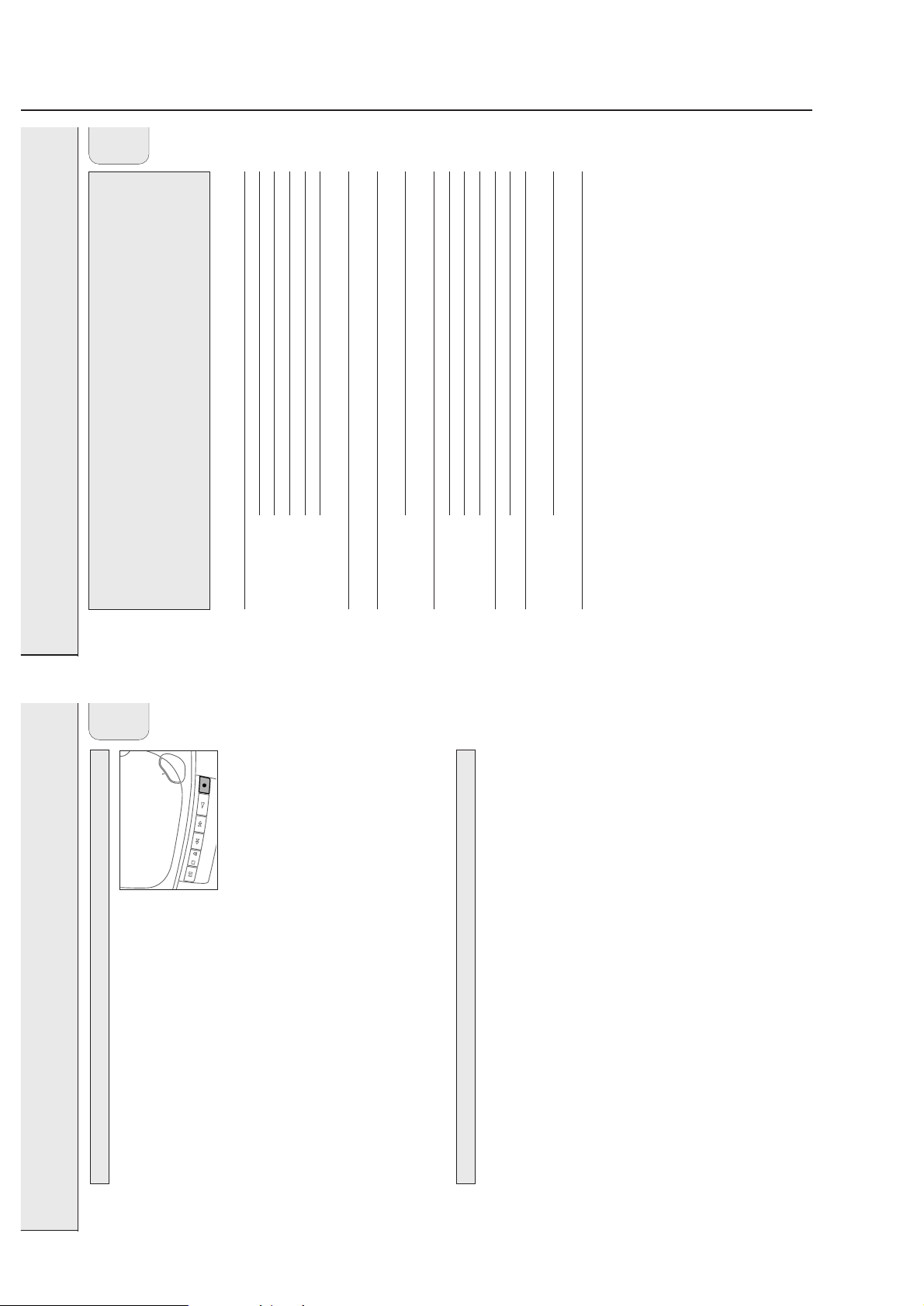
Switching the set on and off
Set the POWER slider to the desired sound source:
CD, TAPE, or BAND (for radio).
BASIC FUNCTIONS RADIO
The set is switched off when the POWER slider is set to OOFFFF/TAPE
English
CD SYN CHRO S TA
BASS
BOOST
CD SYN CHRO S TA
DYNAMIC
POWER
DBB
VOLUME
BASS
BOOST
avoid unnecessary power consumption.
and the keys of the tape deck are released.
Note: If you use batteries, switch the set off after use. This will
Adjusting volume and sound
Adjust the volume using the VOLUME control.
Increase and decrease the bass level by pressing DBB.
The bass level can also be emphasised if you place the set against
wall or shelf. Do not cover any vents; leave sufficient room around
the unit for ventilation.
1700
1300
FM AM
1000
108
800
104
630
100
98
97
OPEN
HRO START RECORD ING
wave band.
Radio – tuning to radio stations
1 Set the POWER slider to FM or MW to select the desired
2 Tune to the desired radio station by using the TUNING wheel.
Improving RADIO reception
For FM stations, pull out the telescopic antenna. To improve the
signal, incline and turn the antenna. Reduce its length if the signal
is too strong (very close to a transmitter).
For MW stations, direct the built-in antenna by turning the whole
set. The telescopic antenna is not needed.
6
English
5
POWER SUPPLY
The mains cable is
The type plate is located
Batteries (optional)
Open the battery compartment of the set and insert 6 batteries,
type R20, UM-1 or D-cells (preferably alkaline).
Remove batteries if they are flat or if the set is not going to be
used for a long time.
Batteries contain chemical substances, so they should be
Mains
disposed of properly.
on the bottom of the set.
corresponds to your local mains voltage. If it does not, consult
your dealer or service organisation.
1 Check whether the mains voltage as shown on the type plate
selector to the local mains voltage.
2 If the set is equipped with a VOLTAGE selector A, set this
inside the battery compartment.
socket. This switches on the mains supply.
3 Connect the mains cable to the AC MAINS socket and the wall
The battery supply will be switched off when the set is connected
to the mains. To change over to battery supply, pull out the plug
from the unit’s AC MAINS socket.
To disconnect the set from the mains completely, remove the mains
plug from the wall socket.
For users in the U.K.: please follow the instructions on page 2.
batteries and old equipment.
Environmental information
All redundant packing material has been omitted. We have done our utmost to make the
packaging easily separable into three mono materials: cardboard (box), polystyrene foam (buffer)
Please observe the local regulations regarding the disposal of packing materials, exhausted
and polyethylene (bags, protective foam sheet).
Your set consists of materials which can be recycled if disassembled by a specialized company.
2-5
CS 49 106
SHUFFLE
REPEAT
ALL
INSTRUCTION FOR USE
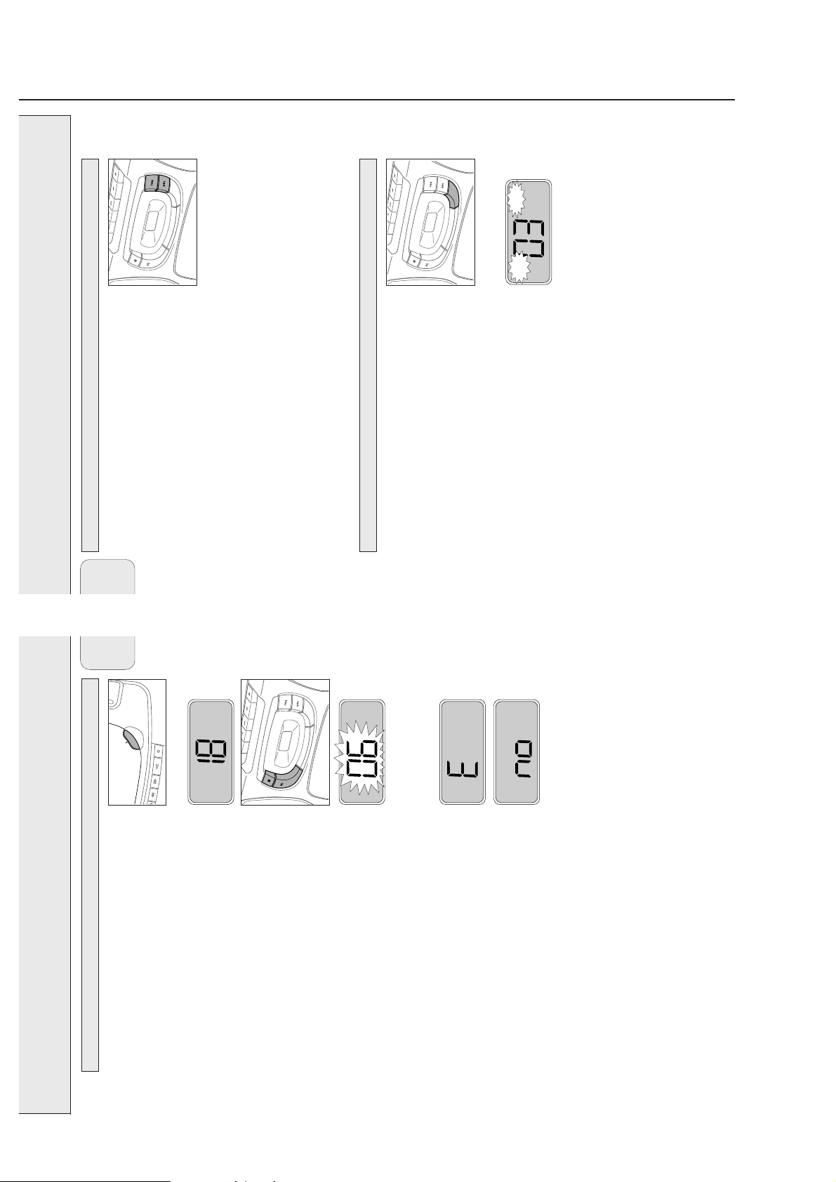
CD PLAYER
CD MODE
CD play continues automatically with the selected track.
Search backward ∞ and forward §
Selecting another track
Briefly press the ∞ or § button once/several times to skip to the
beginning of the current, previous or subsequent track(s).
Press 2; to start CD play.
During CD play:
When CD play is stopped:
English
™ Display indication: the selected track number.
forward or backward direction.
™ CD play continues at a low volume.
Searching for a passage during CD play
1 Hold down the ∞ or § button to find a particular passage in a
2 Release the button when you have reached the desired passage.
is only possible within the particular track.
Note: In the different CD modes or when playing a program, searching
CD MODE
played repeatedly in random order.
SHUFFLE: All tracks of the CD (or program) are played in
SHUFFLE REPEAT ALL: All tracks of the CD (or program) are
random order.
™
to show the different playing modes.
CD MODE: Shuffle and Repeat
™
1 During CD play press CD MODE repeatedly to cause the display
REPEAT: The current track is played repeatedly.™REPEAT ALL: The entire CD (or program) is played repeatedly.
™
indication disappears.
the chosen mode.
2 After 2 seconds of flashing display indication, CD play starts in
3 To return to normal CD play, press CD MODE until the display
8
CD PLAYER
English
OPEN
RECORD
Y
PLA
H
SEARC
ORD
C
Playing a CD
1 Set the POWER slider to CD.
2 Press / OPEN to open the CD compartment.
3 Insert an audio CD (printed side up) and close the CD
CD MODE
Then, the CD player stops. Display indication: the total
number of tracks.
compartment.
™ The CD player starts and scans the contents list of the CD.
™ Display indication: the current track number.
4 Press the 2; button to start CD play.
™ Display indication: the total number of tracks.
5 Press the 9 button to stop CD play.
™ Display indication: the current track number (flashing).
pressing the button again.
You can interrupt CD play by pressing 2;. Continue CD play by
slider.
POWER
– you move the
– the end of the CD is reached, or
– you open the CD compartment,
Note: CD play will also stop if:
If you make a mistake when operating the CD player, or if the
CD player cannot read the CD, the display shows E or no. (See
shows no.
”TROUBLESHOOTING”.)
If you press 2; and there is no CD inserted, the display
7
2-6
CS 49 107
PROGRAM
C
INSTRUCTION FOR USE
OPEN
RECORD
Y
PLA
H
SEARC
D SYN C HRO STA R T RECO R DING
ORD
STOP•REC
PAUSE
Playing a cassette
CASSETTE RECORDER
1 Set the POWER slider to TAPE.
English
English
CD PLAYER
2 Press STOP·OPEN 9 / to open the cassette compartment.
the cassette compartment.
3 Insert a recorded cassette with the open side upwards and close
CD MODE
4 Press PLAY 1 to start playback.
5 Press 6 or 5 to rewind or fast forward the tape.
6 To stop the tape press STOP·OPEN 9 /.
PROGRAM
General information on recording
Note: The keys are released at the end of the tape.
Recording is permissible insofar as copyright or other rights of
third parties are not infringed upon.
For recording on this set you should use a cassette of the type
NORMAL (IEC type I). This deck is not suitable for recording on
PROGRAM
type IV).
cassettes of the type CHROME (IEC type II) or METAL (IEC
The recording level is set automatically. The controls VOLUME and
DBB do not affect the recording.
At the very beginning and end of the tape, no recording will take
place in the 7 seconds during which the leader tape passes the
PROGRAM
recorder heads.
Protecting tapes from accidental erasure
Keep the cassette side to be protected in front of you and snap off
the left tab. Now, recording on this side is no longer possible.
To record again on this side of the cassette, cover the opening with
a piece of adhesive tape.
10
9
PROGRAM disappears and your program
slider.
POWER
From the stop position, press 9.
is erased.
™ no lights up briefly,
– move the
– open the CD compartment, or
– interrupt the power supply,
Note: The program will also be erased if you:
PROGRAM appears on the display. P lights up briefly, then the
number of the stored track is shown.
CD MODE to store the track in the memory.
2 As soon as the number of the desired track is displayed, press
™
CD MODE: Programming track numbers
You can select a number of tracks and store these in the memory
in the desired sequence. You can store any track more than once.
§.
A maximum of 20 tracks can be stored in the memory.
1 When CD play is stopped, select the desired track with ∞ or
for more than 1 second.
3 Select and store all desired tracks in this way.
™ The display shows all stored track numbers in sequence.
4 You can review your settings by pressing and holding CD MODE
Playing the program
If you try to store more than 20 tracks, the display shows F.
Press 2; to play the program.
Erasing the program
2-7
CS 49 108
C
INSTRUCTION FOR USE
English
13
TROUBLESHOOTING
If a fault occurs, first check the points listed
below before taking the set for repair.
If you are unable to solve a problem by
following these hints, consult your dealer or
service center.
WARNING
Under no circumstance should you try to
invalidate the guarantee.
repair the set yourself as this will
English
OPEN
RECORD
Y
PLA
H
SEARC
D SYN C HRO STA R T RECO R DING
ORD
STOP•REC
PAUSE
Mains cable is not securely connected. Connect mains cable properly.
Headphones are connected. Disconnect headphones.
Problem Possible cause Solution
No sound, VOLUME is not adjusted. Adjust volume.
no power
Batteries are flat. Insert fresh batteries.
Batteries are inserted incorrectly. Insert batteries correctly.
Trying to change over from mains to Remove the mains plug from the
reception.
battery supply without removing the plug. unit’s ACMAINS socket.
No reaction to Electrostatic discharge. Disconnect the set from power supply,
Interference caused by electrical equipment Keep the radio away from electrical
operation of any keys reconnect after a few seconds.
Poor radio reception Weak radio signal. Direct the antenna for optimum
like TVs, computers, engines, etc. equipment.
No CD is inserted. Insert a CD.
The CD is inserted upside down. Insert CD with label facing up.
The laser lens is steamed up. Wait until the lens has cleared.
no or E indication The CD is badly scratched or dirty. Replace or clean the CD.
Use of unsuitable cassette types Only use NORMAL type cassettes for
SHUFFLE or PROGRAM is active. Switch off SHUFFLE or PROGRAM.
The CD skips tracks The CD is damaged or dirty. Replace or clean the CD.
(METAL or CHROME) for recording. recording.
sound quality pressure rollers. rollers.
Poor cassette Dust and dirt on the heads, capstans or Clean heads, capstans, and pressure
Recording does Cassette tab(s) may be snapped off. Apply a piece of adhesive tape over
not work the opening.
11
CASSETTE RECORDER
Recording from the CD player – CD synchro start
1 Set the POWER slider to CD.
2 Insert a CD and, if desired, program the track numbers.
4 Insert a blank, unprotected, cassette and close the cassette
compartment.
3 Press STOP·OPEN 9 / to open the cassette compartment.
5 Press RECORD 0 to start recording.
);
§
or
∞
from this very position (use
the beginning of the CD or program.
– if the CD player is in pause mode, recording will start
– if the CD player is in stop mode, recording will start from
™ Playing of the CD or program starts automatically.
6 For brief interruptions press PAUSE ;. Press the PAUSE ; key
again to resume recording.
7 To stop recording, press STOP·OPEN 9 /.
Note: the recording can be started from different positions:
Recording from the radio
1 Tune to the desired radio station (see ”RADIO”).
compartment.
2 Press STOP·OPEN 9 / to open the cassette compartment.
3 Insert a blank, unprotected, cassette and close the cassette
4 Press RECORD 0 to start recording.
the PAUSE ; key again.
5 For brief interruptions press PAUSE ;. To resume recording press
6 To stop recording, press STOP·OPEN 9 /.
2-8
CS 49 109
© WARNING
All ICs and many other semiconductors are susceptible to
electrostatic discharges (ESD). Careless handling during
repair can reduce life drastically.
When repairing, make sure that you are connected with the
same potential as the mass of the set via a wristband with
resistance. Keep components and tools at this potential.
f ATTENTION
Tous les IC et beaucoup d´autres semi-conducteurs sont
sensibles aux décharges statiques (ESD). Leur longévite
pourrait être considérablement écourtée par le fait qu´aucune
précaution nést prise à leur manipulation.
Lors de réparations, s´assurer de bien être relié au même
potentiel que la masse de l´appareil et enfileer le bracelet
serti d´une résistance de sécurité.
Veiller à ce que les composants ainsi que les outils que l´on
utilise soient également à ce potentiel.
d WARNUNG
Alle ICs und viele andere Halbleiter sind empfindlich
gegenüber elektrostatischen Entladungen (ESD).
Unsorgfältige Behandlung im Reparaturfall kann die
Lebensdauer drastisch reduzieren.
Sorgen Sie dafür, daß sie im Reparaturfall über ein Pulsarmband mit Widerstand mit dem Massepotential des
Gerätes verbunden sind.
Halten Sie Bauteile und Hilfsmittel ebenfalls auf diesem
Potential.
ñ WAARSCHUWING
Alle IC´s en vele andere halfgeleiders zijn gevoelig voor
electrostatische ontladingen (ESD).
Onzorgvuldig behandelen tijdens reparatie kan de levensduur
drastisch doen vermindern. Zorg ervoor dat u tijdens reparatie
via een polsband met weerstand verbonden bent met hetzelfde
potentiaal als de massa van het apparaat.
Houd componenten en hulpmiddelen ook op ditzelfde potentiaal.
i AVVERTIMENTO
Tutti IC e parecchi semi-conduttori sono sensibili alle scariche
statiche (ESD).
La loro longevità potrebbe essere fortemente ridatta in caso di
non osservazione della più grande cauzione alla loro
manipolazione. Durante le riparationi occorre quindi essere
collegato allo stesso potenziale che quello della massa
delápparecchio tramite un braccialetto a resistenza.
Assicurarsi che i componenti e anche gli utensili con quali si
lavora siano anche a questo potenziale.
©
Safety regulations require that the set be restored to its
original condition and that parts which are identical with
those specified be used.
Safety components are marked by the symbol
i
Le norme di sicurezza estigono che l´apparecchio venga
rimesso nelle condizioni originali e che siano utilizzati i
pezzi di ricambiago identici a quelli specificati.
Componenty di sicurezza sono marcati con
ñ
Veiligheidsbepalingen vereisen, dat het apparaat in zijn
oorspronkeliijke toestand wordt teruggebracht en dat
onderdelen, identiek aan de gespecificeerde, worden toegepast.
De Veiligheidsonderdelen zijn aangeduid met het symbool
s Varning !
Osynlig laserstrålning när apparaten är öppnad och
spärren är urkopplad. Betrakta ej strålen.
∂ Advarsel !
Usynlig laserstråling ved åbning når sikkerhedsafbrydere
er ude af funktion. Undgå udsaettelse for stråling.
ß Varoitus !
Avatussa laitteessa ja suojalukituksen ohitettaessa olet alttiina
näkymättömälle laserisäteilylle. Älä katso säteeseen !
f
"Pour votre sécurite, ces documents doivent être utilisés par
des spécialistes agréés, seuls habilités à réparer votre
appareil en panne".
ESD
SAFETY
d
Bei jeder Reparatur sind die geltenden Sicherheitsvorschriften zu beachten. Der Originalzustand des Gerätes
darf nicht verändert werden. Für Reparaturen sind Originalersatzteile zu verwenden.
Sicherheitsbauteile sind durch das Symbol markiert.
f
Les normes de sécurité exigent que l`appareil soit remis
à l`état d`origine et que soient utilisées les pièces de
rechange identiques à celles spécifiées.
Les composants de sécurité sont marqués
CLASS 1
LASER PRODUCT
©
DANGER: Invisible laser radiation when open.
©
After servicing and before returning the set to customer
perform a leakage current measurement test from all
exposed metal parts to earth ground, to assure no
shock hazard exists.
The leakage current must not exceed 0.5mA.
AVOID DIRECT EXPOSURE TO BEAM.
©
AVAILABLE ESD PROTECTION EQUIPMENT :
anti-static table mat large 1200x650x1.25mm 4822 466 10953
small 600x650x1.25mm 4822 466 10958
anti-static wristband 4822 395 10223
connection box (3 press stud connections, 1MΩ) 4822 320 11307
extendible cable (2m, 2MΩ, to connect wristband to connection box) 4822 320 11305
connecting cable (3m, 2MΩ, to connect table mat to connection box) 4822 320 11306
earth cable (1MΩ, to connect any product to mat or to connection box) 4822 320 11308
KIT ESD3 (combining all 6 prior products - small table mat) 4822 310 10671
wristband tester 4822 344 13999
WARNINGS & SAFETY
3-1
CS 49 110
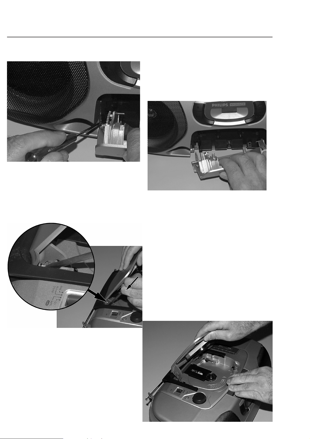
DISMANTLING INSTRUCTIONS
Dismantling of the Cassette Door
• Open cassette door.
• Release left catch by pressing it inwards with a screwdriver
as shown in picture 1.
• Pull door on left side up as shown in picture 2.
• Right catch will now be released automatically.
picture 1
picture 2
Dismantling of the CD Door
• Open CD door.
• Release left catch by pressing it inwards with a screwdriver
as shown in picture 3.
• Pull door on left side up as shown in picture 4.
• Right catch will now be released automatically.
picture 3
picture 4
 Loading...