

Philips AZ-1003 Service manual
CD Stereo Radio Recorder
AZ 1003
MCS200 SL
all versions
Handling Chip Components and Safety ..........................1 - 1
Technical Specification & Service tools...........................2 - 1
Service Measurement......................................................2 - 2
Connections and controls.......................................3 - 1..3 - 2
Disassembly Diagram......................................................4 - 1
Block Diagram .................................................................5 - 1
Wiring Diagram................................................................5 - 2
Control Board
Circuit diagram........................................................6 - 1
Layout diagram........................................................6 - 1
Rectifier Board
Circuit diagram........................................................6 - 2
Layout diagram........................................................6 - 2
Tuner Board
Circuit diagram........................................................7 - 1
Layout diagram........................................................7 - 2
Tuner adjustment ....................................................7 - 2
Recorder Board
Circuit diagram........................................................8 - 1
Layout diagram........................................................8 - 2
Tape deck adjustment.............................................8 - 2
Power Board
Circuit diagram........................................................9 - 1
Layout diagram........................................................9 - 2
CD Board
Circuit diagram......................................................10 - 1
Layout diagram......................................................10 - 2
Exploded view - cabinet.................................................11 - 1
Mechanical partslist.......................................................11 - 2
Electrical partslist .............................................12 - 1 .. 12 - 5
© 3140 785 22950
Published by YT 0228 Service Audio Printed in The Netherlands Subject to modification
TABLE OF CONTENTS
©
Copyright 2001 Philips Consumer Electronics B.V. Eindhoven, The Netherlands
All rights reserved. No part of this publication may be reproduced, stored in a retrieval
system or transmitted, in any form or by any means, electronic, mechanical, photocopying,
or otherwise without the prior permission of Philips.
CLASS 1
LASER PRODUCT
HANDLING CHIP COMPONENTS
1 - 1
© WARNING
All ICs and many other semiconductors are susceptible to
electrostatic discharges (ESD). Careless handling during
repair can reduce life drastically.
When repairing, make sure that you are connected with the
same potential as the mass of the set via a wristband with
resistance. Keep components and tools at this potential.
f ATTENTION
Tous les IC et beaucoup d´autres semi-conducteurs sont
sensibles aux décharges statiques (ESD). Leur longévite
pourrait être considérablement écourtée par le fait qu´aucune
précaution nést prise à leur manipulation.
Lors de réparations, s´assurer de bien être relié au même
potentiel que la masse de l´appareil et enfileer le bracelet
serti d´une résistance de sécurité.
Veiller à ce que les composants ainsi que les outils que l´on
utilise soient également à ce potentiel.
©
Safety regulations require that the set be restored to its
original condition and that parts which are identical with
those specified be used.
Safety components are marked by the symbol
f
Les normes de sécurité exigent que l`appareil soit remis
à l`état d`origine et que soient utilisées les pièces de
rechange identiques à celles spécifiées.
Les composants de sécurité sont marqués
d WARNUNG
Alle ICs und viele andere Halbleiter sind empfindlich
gegenüber elektrostatischen Entladungen (ESD).
Unsorgfältige Behandlung im Reparaturfall kann die
Lebensdauer drastisch reduzieren.
Sorgen Sie dafür, daß Sie im Reparaturfall über ein Pulsarmband mit Widerstand mit dem Massepotential des
Gerätes verbunden sind.
Halten Sie Bauteile und Hilfsmittel ebenfalls auf diesem
Potential.
d
Bei jeder Reparatur sind die geltenden Sicherheitsvorschriften zu beachten. Der Originalzustand des Gerätes
darf nicht verändert werden. Für Reparaturen sind Originalersatzteile zu verwenden.
Sicherheitsbauteile sind durch das Symbol markiert.
ESD
SAFETY
ñ WAARSCHUWING
Alle IC´s en vele andere halfgeleiders zijn gevoelig voor
electrostatische ontladingen (ESD).
Onzorgvuldig behandelen tijdens reparatie kan de levensduur
drastisch doen vermindern. Zorg ervoor dat u tijdens reparatie
via een polsband met weerstand verbonden bent met hetzelfde
potentiaal als de massa van het apparaat.
Houd componenten en hulpmiddelen ook op ditzelfde potentiaal.
i AVVERTIMENTO
Tutti IC e parecchi semi-conduttori sono sensibili alle scariche
statiche (ESD).
La loro longevità potrebbe essere fortemente ridatta in caso di
non osservazione della più grande cauzione alla loro
manipolazione. Durante le riparationi occorre quindi essere
collegato allo stesso potenziale che quello della massa
delápparecchio tramite un braccialetto a resistenza.
Assicurarsi che i componenti e anche gli utensili con quali si
lavora siano anche a questo potenziale.
ñ
Veiligheidsbepalingen vereisen, dat het apparaat in zijn
oorspronkeliijke toestand wordt teruggebracht en dat
onderdelen, identiek aan de gespecificeerde, worden toegepast.
De Veiligheidsonderdelen zijn aangeduid met het symbool
i
Le norme di sicurezza estigono che l´apparecchio venga
rimesso nelle condizioni originali e che siano utilizzati i
pezzi di ricambiago identici a quelli specificati.
Componenty di sicurezza sono marcati con
©
DANGER: Invisible laser radiation when open.
AVOID DIRECT EXPOSURE TO BEAM.
s Varning !
Osynlig laserstrålning när apparaten är öppnad och
spärren är urkopplad. Betrakta ej strålen.
∂ Advarsel !
Usynlig laserstråling ved åbning når sikkerhedsafbrydere
er ude af funktion. Undgå udsaettelse for stråling.
CLASS 1
LASER PRODUCT
ß Varoitus !
Avatussa laitteessa ja suojalukituksen ohitettaessa olet alttiina
näkymättömälle laserisäteilylle. Älä katso säteeseen !
©
After servicing and before returning the set to customer
perform a leakage current measurement test from all
exposed metal parts to earth ground, to assure no
shock hazard exists.
The leakage current must not exceed 0.5mA.
f
"Pour votre sécurite, ces documents doivent être utilisés par
des spécialistes agréés, seuls habilités à réparer votre
appareil en panne".

2 - 1
TECHNICAL SPECIFICATIONS
GENERAL
Mains voltage -/00C : 230 V
-/01 : 120 / 230 V
-/05/10 : 240V
-/17 : 120 V
Mains frequency
-/00C/05/10 : 50 Hz
-/01 : 50 / 60 Hz
-/17 : 60 Hz
Battery : 9 V (R14/UM-2/C-size x 6)
Power consumption : 12 W
Dimension (W x H x D) : 360 x 225 x 152mm
Weight : 2.3 Kg
AMPLIFIER
Output power mains : 2 x 1 W
battery : 2 x 1 W
Speaker impedance : 2 x 8 ohm
Frequency response : 100 Hz - 10 kHz (±3dB)
TUNER - F M SECTION
Tuning range : 87.5 - 108 MHz
IF frequency : 10.7 MHz ± 0.2 MHz
Sensitivity : 28 dBf at 26dB S/N
Selectivity : 24 dB at 300kHz
IF rejection : 65 dB
Image rejection : 26 dB
TUNER - A M SECTION
Tuning range : 512 - 1635 kHz
-/17 : 520 - 1700 kHz
IF frequency : 468 kHz ± 3 kHz
Sensitivity : 4000 µV/m at 26dB S/N
Selectivity : 20 dB
IF rejection : 70 dB
Image rejection : 32 dB
AUDIO CASSETTE RECORDER
Number of tracks : 1 stereo
Tape speed : 4.76 cm/sec ± 3%
Wow & flutter : < 0.48 JIS UWTD
Fast wind/rewind C60 : 130 sec.
Frequency response P/B : 125 - 8000 Hz
S/N ratio : ≥ 36 dB
COMPACT DISC
Frequency response : 100 Hz - 10 kHz
S/N ratio : 60 dB
Channel difference 1 kHz : 2 dB
Channel crosstalk 1 kHz : 40 dB
Laser wavelength : 780 ± 20 nm
Laser light power : < 0.5 mW
SERVICE TOOLS
Audio signal disc SBC 429.......................................................................4822 397 30184
Playability test disc SBC 444
Test disc 5 (disc without errors ) +
Test disc 5A (disc with dropout errors, black spots and fingerprints)
SBC 426/426A.....................................................................4822 397 30096
Burn in test disc (65 min. 1kHz signal at -30 dB level without “pause”)
...................................................................4822 397 30245
.....4822 397 30155
AVAILABLE ESD PROTECTION EQUIPMENT
anti-static table mat
anti-static wristband
connection box (3 press stud connections, 1MΩ) 4822 320 11307
extendible cable (2m, 2MΩ, to connect wristband to connection box) 4822 320 11305
connecting cable (3m, 2MΩ, to connect table mat to connection box) 4822 320 11306
earth cable (1MΩ, to connect any product to mat or to connection box) 4822 320 11308
KIT ESD3 (combining all 6 prior products - small table mat) 4822 310 10671
wristband tester 4822 344 13999
large 1200x650x1.25mm 4822 466 10953
small 600x650x1.25m 4822 466 10958
4822 395 10223
2 - 2
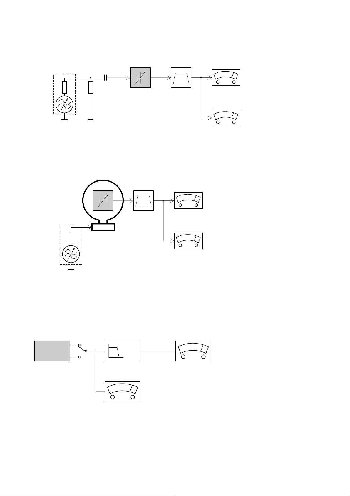
SERVICE MEASUREMENT
Tuner SW
RF Generator
e.g. PM5326
Aerial replacement
DUT
Capacitor
Ri=50Ω
R=50Ω
Bandpass
250Hz-15kHz
e.g. 7122 707 48001
LF Voltmeter
e.g. PM2534
S/N and distortion meter
e.g. Sound Technology ST1700B
To avoid atmospheric interference all AM-measurements have to be carried out in a Faraday«s cage.
Use a bandpass filter (or at least a high pass filter with 250Hz) to eliminate hum (50Hz, 100Hz).
Tuner AM (MW,LW)
RF Generator
e.g. PM5326
Ri=50Ω
DUT
Frame aerial
e.g. 7122 707 89001
Bandpass
250Hz-15kHz
e.g. 7122 707 48001
LF Voltmeter
e.g. PM2534
S/N and distortion meter
e.g. Sound Technology ST1700B
To avoid atmospheric interference all AM-measurements have to be carried out in a Faraday«s cage.
CD
Use Audio Signal Disc SBC429 4822 397 30184 (replaces test disc 3)
L.P.F. = 13
th
order filter 4822 395 30204
DUT
L
R
Low pass filter 22kHz
LEVEL METER
e.g. Sennheiser UPM550
with FF-filter
S/N and distortion meter
e.g. Sound Technology ST1700B
3 - 1
Top and front panels (See 1)
1
VOLUME– to adjust volume level
2
Source selector : CD, TUNER, TAPE/
POWER OFF
–
selects CD, tuner or tape source of sound
–
power off switch
3
CD door
4
TUNING
– tunes to radio stations
5 BAND –
selects waveband
6
PREVIOUS, NEXT ∞ , §
–
skips or searches a passage/track
backwards or forward
7 PROG – programs and reviews
programmed track numbers
8 CASSETTE RECORDER keys:
;
–
pauses playback or recording
9
/ –
stops the tape;
–
opens the cassette holder
5 or 6
–
fast rewinds/ winds tape
2
–
starts playback
0
–
starts recording
9 Cassette door
0 CD Display
–
shows the CD functions
! PLAY/PAUSE 2; - starts or pauses CD playback.
@ STOP 9
–
stop playback;
–
erases a CD program.
Back panel
# Telescopic antenna - improves FM
reception.
Note: AM band antenna is built into set (see Tuner
reception)
$ Battery door - open to insert 6 x 1.5V
R-14/ UM2/ C-cells.
% AC POWER/MAINS - inlet for power cord.
^ Voltage selector – (inside the battery compartment, not all
versions) adjust to match the local voltage 110/220V before
plugging in the set.
CONNECTIONS AND CONTROLS
0 9! 8 7
321
4
5
#
6@
$
%
^
6 x R14 / UM-2 / C-CELLS

3 - 2
Power Supply
Whenever convenient, use the mains supply cord if you want to
conserve battery life. Make sure you remove the plug from the
set and wall outlet before inserting batteries.
Batteries (not included)
Open the battery compartment and insert six batteries, type R14, UM-2 or C-cells, (preferably alkaline) with the correct
polarity as indicated by the "+" and "–" symbols inside the
compartment. (See 1)
Replace the compartment door, making sure the batteries are
firmly and correctly in place. The set is now ready to operate.
Batteries contain chemical substances, so they should be
disposed of properly.
Incorrect use of batteries can cause
electrolyte leakage and will corrode the
compartment or cause the batteries to burst:
Do not mix battery types: e.g. alkaline with carbon zinc. Only use
batteries of the same type for the set.
When inserting new batteries, do not try to mix old batteries
with the new ones.
Remove the batteries if the set is not to be used for a long time.
Using AC Mains
Check if the power/mains voltage, as shown on the type
plate located on the
bottom of the set, corresponds to your local power supply. If
it does not, consult your dealer or service center.
Connect the power cord to the AC POWER/MAINS inlet and
the wall socket. The mains lead is now connected and ready for
use.
To switch the set off completely, withdraw the power cord from
the wall socket.
Disconnect the mains lead from the wall socket to protect your
set during heavy
thunderstorms.
The type plate is located on the bottom of the set.
Switching POWER on/off:
Save energy
To avoid unnecessary energy consumption, always adjust the
source selector to
TAPE/
POWER OFF
after using the set.
Also check that the tape deck keys are released.
General operation
1 To select your sound source adjust the source selector to :
CD, TUNER or
TAPE/
POWER OFF
.
2 Adjust the sound with the VOLUME control.
3 To switch off the set, adjust the source
selector to
TAPE/
POWER OFF
position and check the cassette
keys are released.
Trouble shooting
Problem
– Possible cause
• Remedy
No sound /power
– Volume not adjusted
• Adjust the VOLUME
– Power cord not securely connected
• Connect the AC power cord properly
– Batteries dead/ incorrectly inserted
• Insert (fresh) batteries correctly
Display does not function properly/ No reaction to
operation of any of the controls
– Electrostatic discharge
• Switch off and unplug the set. Reconnect after a few seconds
The CD skips tracks
– CD damaged or dirty
• Replace or clean CD
– Program is active
• Quit program mode
-- indication
– No CD inserted
•
Insert a CD
– CD badly scratched or dirty
•
Replace/ clean CD, see Maintenance
– Laser lens steamed up
• Wait until lens has cleared
– CD-R is blank or not finalized/ CD-RW inserted
•
Use a finalized CD-R or suitable CD Audio disc only
Poor cassette sound quality
– Dust and dirt on the heads, etc.
• Clean deck parts, see Maintenance
– Use of incompatible cassette types (METAL or CHROME)
• Only use NORMAL (IEC
I
) for recording
Recording does not work
– Cassette tab(s) may be broken
• Apply adhesive tape over the missing tab space
CONNECTIONS AND CONTROLS
For more information on operation instruction please visit Philips Audio internet site :
http://www.audio.philips.com
4 - 14 - 1
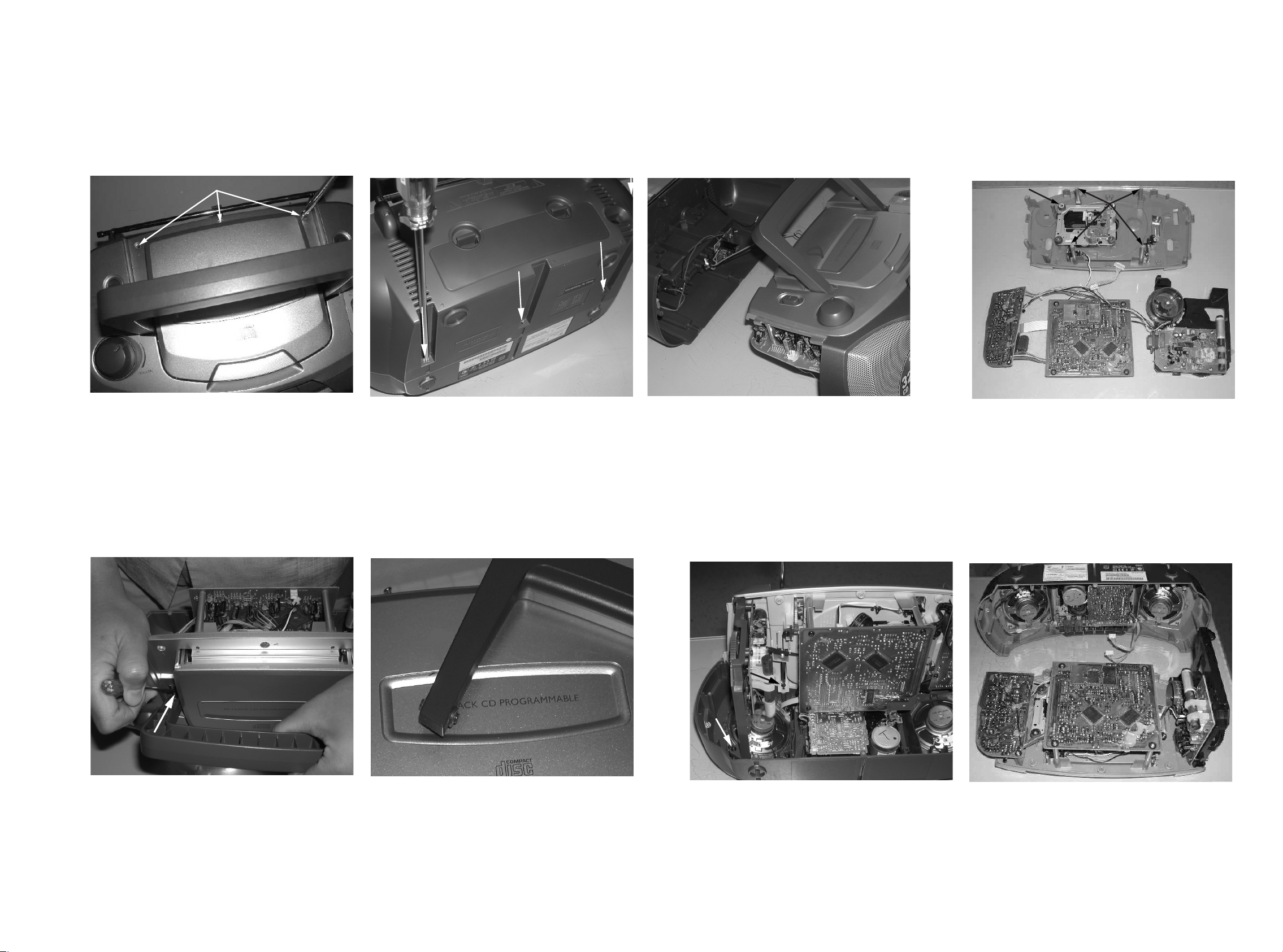
DISASSEMBLY DIAGRAM
A. REMOVE BACK CABINET ASSEMBLY
- REMOVE SCREWS A1(3x10) 3PCS
- REMOVE SCREWS A2(3x30) 5PCS
- REMOVE BACK CABINET
B.REMOVE HANDLE
- PRESS DOWN THE STOPER AND
PULL HTE HANDLE OUT
- REMOVE HANDLE
C REMOVE TOP CABINET ASSEMBLY
- REMOVE SCREWS C3(3x20) 2PCS
- REMOVE SCREWS C4(3x10) 1PC
- REMVOE TOP CABINET
D REMOVE DECK MECHANISM
- REMOVE SCREWS D5(3x10) 4PCS
- REMOVE SCREWS D6(2.5x10) 4PCS
A1
A2
D6
D5
C3
C4
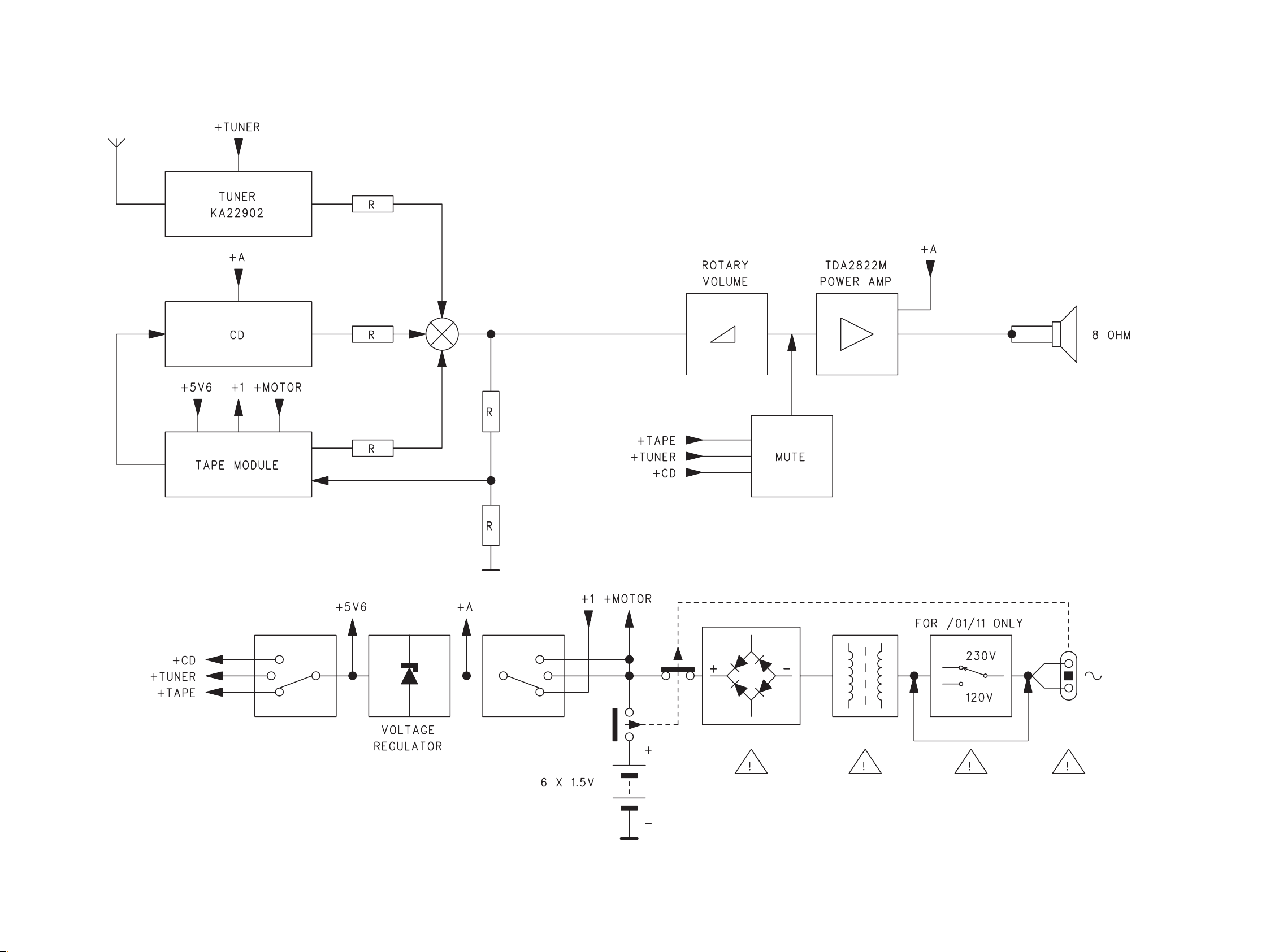
5 - 1 5 - 1
BLOCK DIAGRAM
 Loading...