

Page 1

For internal use only PHILIPS
ISSUE AS2000.02 (00-02-10)
Published by:
Service Depar tment Audio Systems
LINE OF BUSINESS AUDIO SYSTEMS
02.01 TYPENUMBER(S): CDR200, CDR538, CDR560, CDR760, CDR765
INFORMATION : For repair of the power supply unit a special service kit containing the
mosts sensitive components has been created.
It can be ordered with service codenumber 3122 785 90130.
The service kit contains the following parts:
1120, 3109, 3113, 3126, 3127, 3128, 6113, 6210, 7110, 7125, 7200
REMARKS :
02.02 TYPENUMBER(S): CDR200, CDR538, CDR560, CDR760, CDR765
SYMPTOM :
Power supply is defective.
CURE : It is advised to repleace the following items:
• pos. 7125 (STP4 or STP3) by STP5
• pos. 6210 (PBYR745) by PBYR10100
REMARKS : For repair of the power supply unit a special service kit
3122 785 90130 is available (see 02.01 for details).
Items 6210 and 7125 can also be ordered separately:
Pos Codenumber Article description
—————————————————–————6210 9340 205 70127 PBYR10100
7125 9322 126 65687 STP5
1111IRIS CODE
SERVICE NEWSLETTER
Service Newsletter 2000 – Audio Systems 1/6
Page 2

02.03 TYPENUMBER(S): CDR200, CDR538, CDR560, CDR760, CDR765
SYMPTOM :
Short interruptions in recordings.
CURE : The problem is most probably caused by unstable operation of the
power supply. It is advised to repleace the following items:
• pos. 7125 (STP4 or STP3) by STP5
• pos. 6210 (PBYR745) by PBYR10100
REMARKS : For repair of the power supply unit a special service kit
3122 785 90130 is available (see 02.01 for details).
Items 6210 and 7125 can also be ordered separately:
Pos Codenumber Article description
—————————————————–————6210 9340 205 70127 PBYR10100
7125 9322 126 65687 STP5
02.04 TYPENUMBER(S): CDR770
INFORMATION : The correct codenumber for the complete (and adjusted)
CDR-Module reads 3104 129 52521.
For this module a central repair procedure has been initiated.
The loader assembly, pos. 81 in the partslist (9305 043 20901),
cannot be used for repair because the CDL4009 needs an extra
adjustment on the mainboard which cannot be carried out on first
level.Please do not order these loaders, as they are reserved for the
central repairshop only.
REMARKS :
02.05 TYPENUMBER(S): FW-C1, FW-C3, FW-C10, FW-C30, FW-C35
SYMPTOM :
The cassette door will not open completely when a cassette is inside
the cassette compartment.
CURE : The capstan pin (pos. 41) of the tape mechanism will not disengage
fully from the cassette tape.The problem is caused by a combination
of the following:
a) Leaf springs (pos. 199) which are responsible to create a rotating
movement for the cassette during “door eject” are too weak to
push the cassette out of the capstan pin.
b) Mis-matched housing parts of the cassette (see fig. 1) rub/scratch
against the support ribs of the cassette door (pos. 200).
c) Uneven cassette door support ribs create an additional fr iction to
the rotating movement of the cassette.
X761IRIS CODE
6651IRIS CODE
Service Newsletter 2000 – Audio Systems 2/6
Page 3
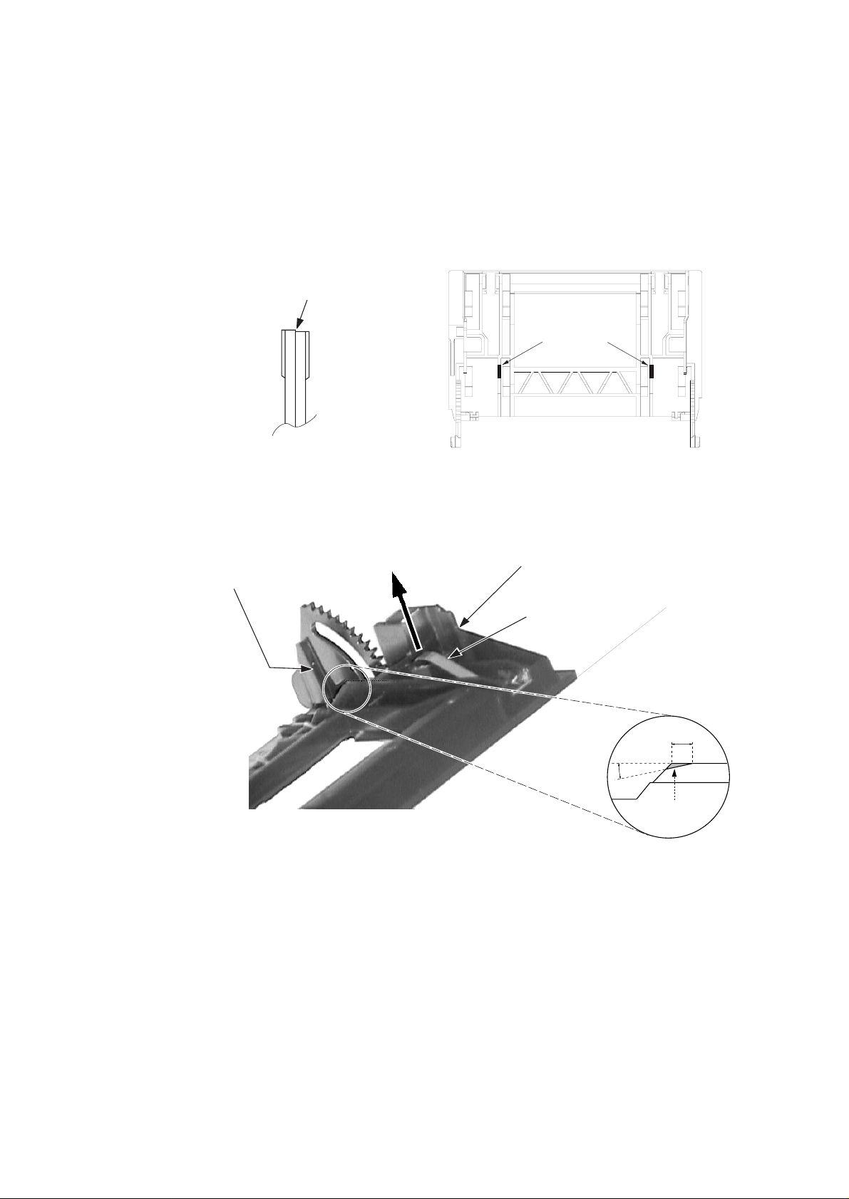
The problem is resolved by:
1) Cutting 2 ribs (both sides) on the cassette door in order to enable
a bigger rotational movement for the door during eject
(see figure 2 & 3).
2) Increasing the spring force on the cassette by pulling the spring in
the direction and up to the level shown in figure 3.
Caution: Ensure that the cassette is able to smoothly slide into the
cassette door before returning the set to the customer !
REMARKS :
3mm
Cut away this
shaded area
15
o
Figure 3. Portion of the Cassette door
Horizontal Line
Leaf Spring should not
be higher than this corner
of the cassette door
Cassette support
rib that is uneven
Pull Leaf Spring in
this direction
Problem Leaf
Spring
Mis-match cassette tape
housing (bare tape side)
Figure 1. Portion of Problem
Cassette Tape
Figure 2. Location of the ribs for rework
The 2 ribs that
must be cut lower
Service Newsletter 2000 – Audio Systems 3/6
Page 4
02.06 TYPENUMBER(S): FW-C1, FW-C3, FW-C10, FW-C28, FW-C30, FW-C35, FW-C38,
FW-C39
SYMPTOM :
A high frequency pitch (around 4kHz - 5kHz) is audible from the front
display panel in quiet environment.
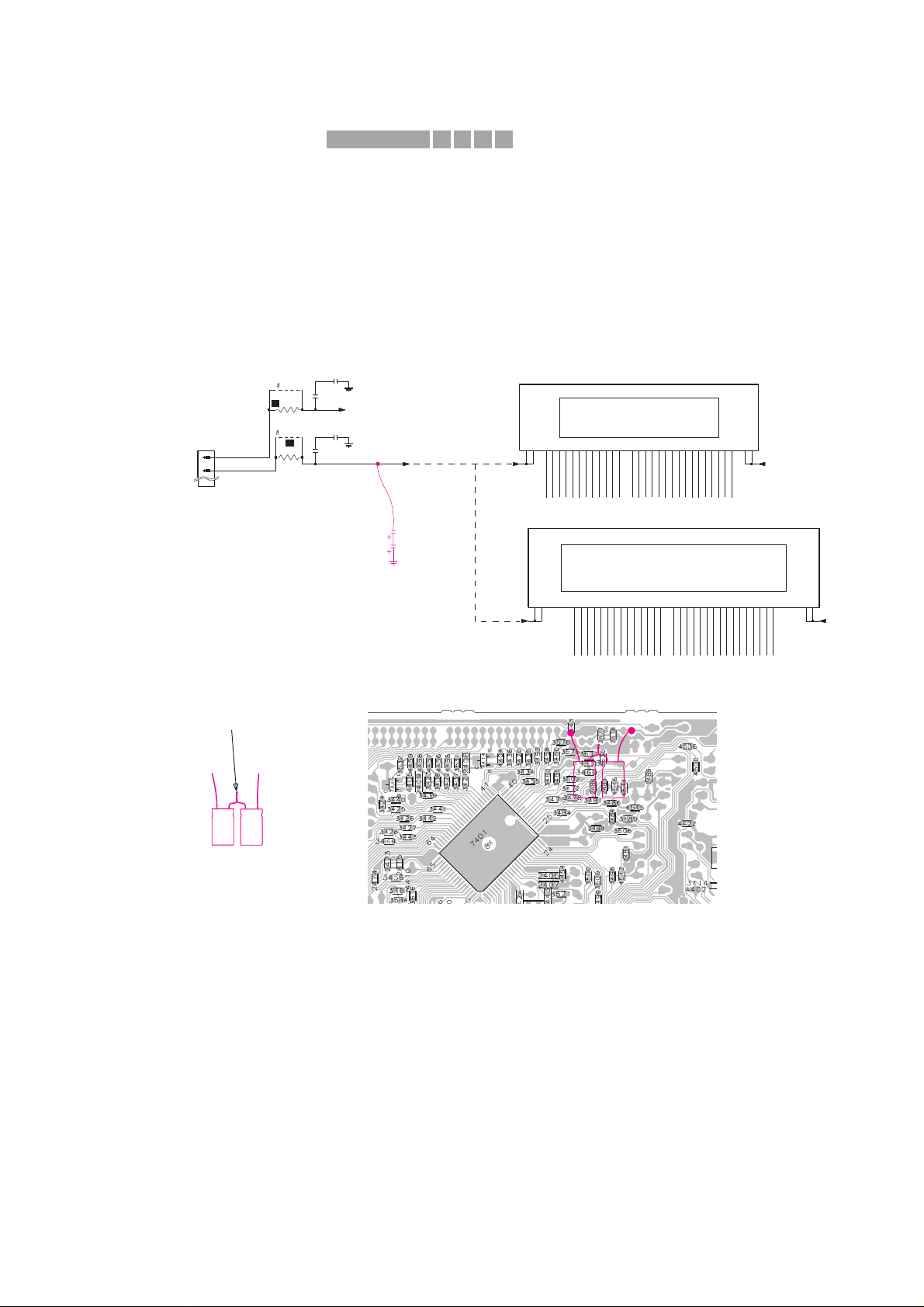
CURE : The source of the noise comes from the filtering SMD capacitors
2418, 2420, 2476 and 2477.
The problem is resolved by adding 2 elcaps of 4,7µF
(4822 124 40769) in series across the existing SMDs capacitors of
the -F2 supply line.
The elcaps can by soldered onto the copperside of the Front board as
indicated in the circuit and SMD layout view below.
Rework procedure:
1) Dismantle the Cover CDC and Front assembly.
2) Prepare the 2 elcaps of 4,7µF (4822 124 40769) in series.
3) Place an insulation tape onto the Front board (area under the
elcaps) to prevent the elcaps and their leads from short-circuiting
to the surrounding SMD components and pads.
4) Position the elcaps horizontally over the insulation tape and solder
them to the copper pads as shown.
Make sure that the elcaps are close to the Front board so that
there is no contact to the moving parts of the CDC module.
5) Re-assemble the Front assembly and Cover CDC.
REMARKS :
F1
F2
1R
3483
9522
9521
3471
1R
2476
1u
FTD
FTD
1u
2477
1401
15
16
1u
2418
8
P147P156P16
5
P0318P0417P0516P0615P0714P0813P0912P10
11
10
P119P12
P13
26
09G2510G2411G2312G
22
F1a1F1b
2
F2a39F2b
38
P0120P02
19
1400
BJ722GNK
01G3302G3203G3104G3005G
29
28
06G2707G
08G
2420
1u
F2
F1
F2
F1
12
P1511P16
10
23
P0422P0521P06
20
19
P07
P0818P0917P1016P1115P1214P1313P14
11G
30
29
12G2813G2714G
F1a1F1b
2
F2a49F2b
48
P0125P0224P03
1438
HN-14NN12T
01G4002G
39
38
03G
04G3705G3606G3507G3408G3309G3210G
31
F2 F1
Large FTD Display
Small FTD Display
FTD
4u7
4u7
-
-
+
+
Pre-prepared
elcos in series
Twist & soldered together
Portion of the Front Board (SMD side)
-
-
+
+
Portion of the Front Circuit
X411IRIS CODE
Service Newsletter 2000 – Audio Systems 4/6
Page 5
02.07 TYPENUMBER(S): FW-C50, FW-C55, FW-C58, FW-C70, FW-C71, FW-C72, FW-P73,
FW-P-75, FW-P78
SYMPTOM :
A high frequency pitch (around 4kHz - 5kHz) is audible from the front
display panel in quiet environment.
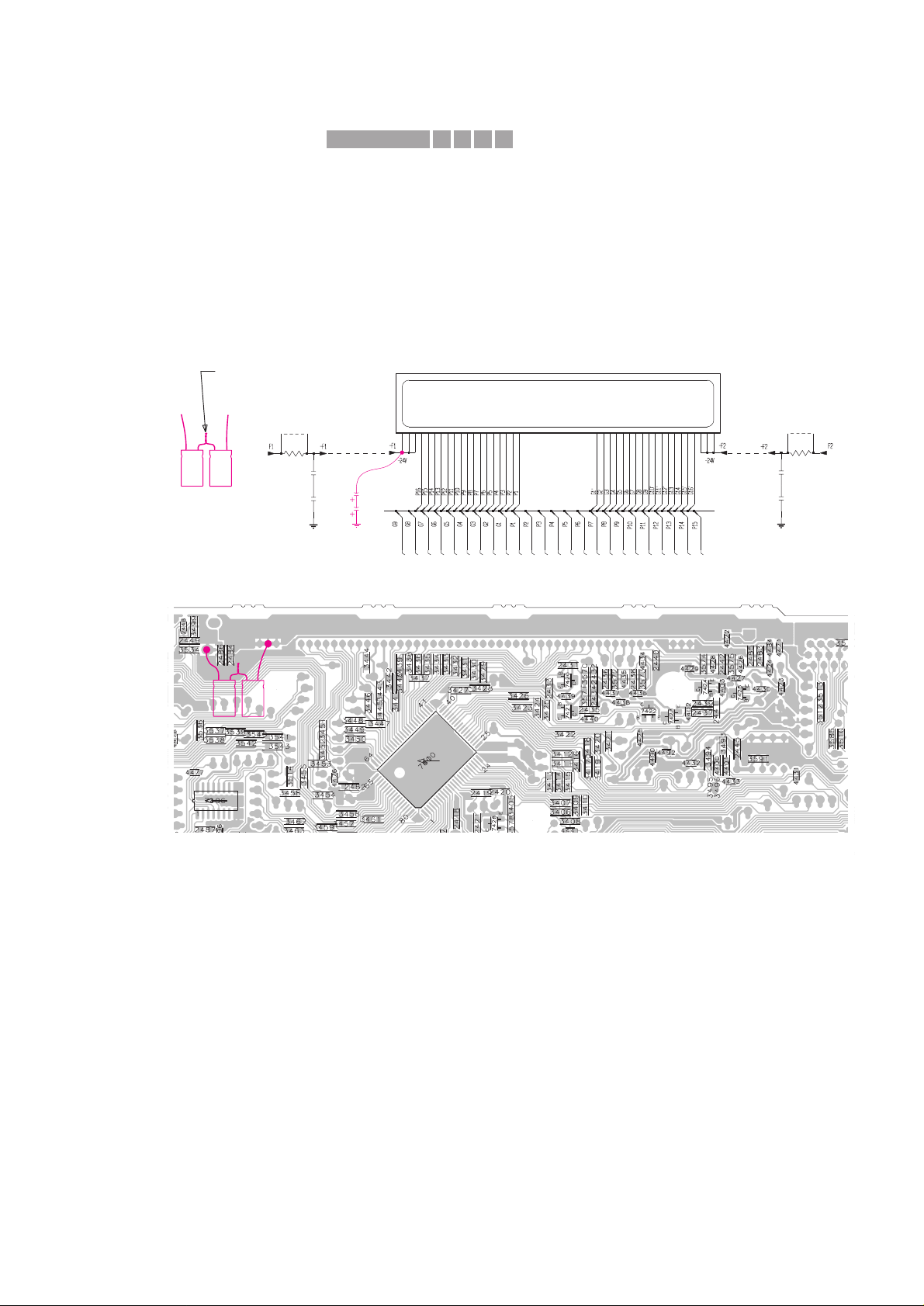
CURE : The source of the noise comes from the filtering SMD capacitors
2483 - 2486 for the FTD display supply -F1 and -F2.
The problem is resolved by adding 2 elcaps of 4,7µF
(4822 124 40769) in series across the existing SMDs capacitors of
the -F1 supply line.
The elcaps can by soldered onto the copperside of the Front board as
indicated in the circuit and SMD layout view below.
Rework procedure:
1) Dismantle the Rear Cover, Cover CDC and CDC Module.
2) Prepare the 2 elcaps of 4,7µF (4822 124 40769) in series.
3) Place an insulation tape onto the Front board (area under the
elcaps) to prevent the elcaps and their leads from short-circuiting
to the surrounding SMD components and pads.
4) Position the elcaps horizontally over the insulation tape and solder
them to the copper pads as shown.
Make sure that the elcaps are close to the Front board so that
there is no contact to the moving parts of the CDC module.
5) Re-assemble the CDC Module, Cover CDC and Rear Cover.
REMARKS :
3430
3448
1u
2486
3438
3434
41 42 4344 45 46 47 48 5152 536 7 8 9 26 27 28293 30 3132 33 34 35 36 3738 39 4011 1213 14 15 16 17 18192 202122232425
1415
110
3446
3442
3447
D
1u
2483
3443
3451
3452
3431
3436
3439
3437
3435
2485
1u
D
1R
3560
3449
9401
3561
1R
3433
9400
3432
3444
3450
3440
3441
3445
3429
2484
1u
FTD Display
D
4u7
4u7
Portion of the Front Circuit
Portion of the Front Board (SMD side)
-
-
+
+
-
-
+
+
Pre-prepared
elcos in series
Twist & soldered together
X411IRIS CODE
Service Newsletter 2000 – Audio Systems 5/6
Page 6

02.08 TYPENUMBER(S): FW748P, FW-P73, FW-P75
SYMPTOM :
In DPL mode the volume increases spontaneously and turns back to
normal level later (especially at the center loudspeaker).
CURE : The problem is caused by insufficient current on the VOL_CLK
(DPL_V_CLK) line to drive pin 5 of the Volume IC 7712 M62429FP
on the AF board.
This is solved by changing resistor 3416 on the Front Board from
2,2kΩ to 680Ω (4822 117 10361).
REMARKS :
02.09 TYPENUMBER(S): SD100
INFORMATION : On special request the MPEG Board has been added to the service
parts list.
Pos Codenumber Article description
––—————————————————–————————1001 3141 018 01780 MPEG Board for SD100/00M
1001 3141 018 01890 MPEG Board for SD100/01M
REMARKS :
X25CIRIS CODE
Service Newsletter 2000 – Audio Systems 6/6
 Loading...