

Page 1

Service Manual
M4735A Defibrillator/Monitor
Verification Draft
29 June 2000
Page 2

Notice
About This Edition
Edition 1
Printed in the USA
Publication number M4735-90900
The information in this manual appli es
to the M4735A Heartstream XL
Release A.0.0. This informatio n is subject to change without notice.
Agilent Technologies shall not be liabl e
for errors contained herein or for incidental or consequential damages in connection with the furnishing,
performance, or use of this material.
Edition History
Edition 1, July, 2000
Copyright
Copyright © 2000
Agilent Technologies, Inc.
3000 Minuteman Road
Andover, MA 01810-1099 USA
(978) 687-1501
This document ma y not be photoc opied,
reproduced, or translated to another language without prior written consent of
Agilent Technologies.
WARNING
Radio Frequency (RF) interference
from nearby transmitting devices may
seriously degrade performance of the
M4735A. Electromagnetic compatibility with surrounding devices should be
assessed prior to using the defibrillator.
CAUTION
Use of supplies or accessories other
than those recommended by Agilent
Technologies may compromise product
performance.
THIS PRODUCT IS NOT INTENDED
FOR HOME USE.
IN THE U.S., FEDERAL LAW
RESTRICTS THIS DEVICE TO SALE
ON OR BY THE ORDER OF A PHYSICIAN.
Medical Device Directive
The M4735A Defibrillator/Monito r
complies with the requirements of the
Medical Device Directive 93/42/EEC
and carries the
ingly.
Authorized EU-representative:
Agilent Technologies GmbH
Herrenbergerstrasse 130
D-71034 Boeblingen,
Germany
Fax: +49-7031-14-2346
mark accord-
0123
ii
Page 3

Conventions
This manual uses the following text conventions:
Printed and On-Line
NOTE Notes contain additional information on servicing this product.
CAUTION Caution statements descr ibe cond ition s or acti ons that can resu lt in damag e to
the equipment or loss of data.
WA RN I N G Warning statements describe conditions or actions that can result in personal injury
or loss of life.
Te x t
Softkey
On-Line Only
Hypertext
represents messages that appear on the display
represents softkey labels that appear on the display
above or below the button to which they correspond
represent hypertext links, which will display as blue;
click on the link to go t o that d estin ation, then cl ick on
the destination to return.
iii
Page 4

This page intentionally left blank
iv
Page 5

Contents
Conventions
Printed and On-Line .......................................................................................................... iii
On-Line Only ................................................................................................................. iii
Hypertext ..........................................................................................................................iii
Introduction
Overview ....................................................................................................................1-1
Defibrillator/Monitor ...................................................................................................... 1-1
Batteries .......................................................................................................................... 1-2
Installation ......................................................................................................................1-2
Upgrades ......................................................................................................................... 1-2
Preventive Maintenance .................................................................................................. 1-2
Repair Philosophy ........................................................................................................... 1-3
Performance Verification and Safety Tests
Overview .........................................................................................................................2-1
Chapter Contents ............................................................................................................. 2-1
Mandatory Testing ......................................................................................................2-2
External Repairs/No Trouble Found ............................................................................... 2-2
Printer ..............................................................................................................................2-3
Internal Repairs ...............................................................................................................2-3
Test Matrix .................................................................................................................2-4
Test Equipment ...........................................................................................................2-8
Configuration and Diagnostic Modes ......................................................................2-10
Configuration Mode ...................................................................................................... 2-10
Diagnostic Mode ........................................................................................................... 2-11
The Software Support Tool ......................................................................................2-12
Using the Support Tool ................................................................................................. 2-12
Performance Verification .........................................................................................2-14
Visual Inspection ........................................................................................................... 2-15
Functional Checks ......................................................................................................... 2-16
Diagnostic Tests ............................................................................................................ 2-19
Safety Tests ..................................................................................................................2-39
Battery Capacity Test ....................................................................................................2-40
6/29/00
v
Page 6

Contents
Troubleshooting
Overview .........................................................................................................................3-1
Chapter Contents ............................................................................................................. 3-1
Repair Philosophy ........................................................................................................... 3-1
Equipment Required .......................................................................................................3-1
Troubleshooting and Repair Methodology ................................................................3-2
Methodology Overview .................................................................................................. 3-2
Initial Assessment ......................................................................................................3-3
Diagnosing External Failures .....................................................................................3-4
Diagnosing Internal Failures ......................................................................................3-5
Troubleshooting Tables ..............................................................................................3-6
Using the Tables ............................................................................................................. 3-6
General Problems .......................................................................................................3-8
Unit Unresponsive .......................................................................................................... 3-8
Error Codes ................................................................................................................... 3-10
System Messages .......................................................................................................... 3-12
Momentary Messages ...................................................................................................3-14
Audio Tones ................................................................................................................ 3-16
Extended Self Test Failures .......................................................................................... 3-17
Operational Problems ...............................................................................................3-18
ECG Monitoring ......................................................................................................... 3-18
SpO2 Monitoring .......................................................................................................... 3-20
Defibrillation and Cardioversion .................................................................................3-21
Pacing ............................................................................................................................3-24
Printer ........................................................................................................................... 3-25
Display .......................................................................................................................... 3-26
Audio ............................................................................................................................3-27
Keys .............................................................................................................................3-28
Battery and Charging Circuits ...................................................................................... 3-29
Data Card ......................................................................................................................3-30
Calling for Service ................................................................................................... 3-31
United States of America ..............................................................................................3-31
Canada ..........................................................................................................................3-31
Other International Areas .............................................................................................. 3-31
Equipment Information ................................................................................................. 3-31
Removal and Replacement
Overview .........................................................................................................................4-1
Chapter Contents ............................................................................................................. 4-1
Servicing Notes ..........................................................................................................4-1
Key Components ............................................................................................................. 4-1
Removal, Handling, and Replacement ........................................................................... 4-2
Tool Requirements .......................................................................................................... 4-3
vi
Page 7

Contents
Disposal ..........................................................................................................................4-3
External Assemblies ...................................................................................................4-4
User-replaceable Parts and Accessories .......................................................................... 4-5
User Maintenance ...........................................................................................................4-5
Printer Assembly ............................................................................................................. 4-6
Battery Cover ................................................................................................................ 4-10
Main Fuse ..................................................................................................................... 4-12
Battery Eject Assembly ................................................................................................ 4-14
Data Card Door .............................................................................................................4-16
Energy Select Knob ....................................................................................................4-17
Paddle Holders .............................................................................................................. 4-18
Labels ............................................................................................................................4-20
Label Descriptions ........................................................................................................ 4-20
Removing and Replacing Labels .................................................................................. 4-22
Opening the Case ..................................................................................................... 4-24
Discharge the Power Supply Capacitors ...................................................................... 4-24
Separate the Case ........................................................................................................ 4-26
Discharge the Defibrillator Capacitor .......................................................................... 4-30
Identifying Internal Subassemblies ...............................................................................4-32
Internal Assemblies - Top Case ................................................................................4-33
Lithium Backup Battery ................................................................................................ 4-34
Control PCA ................................................................................................................ 4-36
Shield Plate ...................................................................................................................4-40
Keyscan PCA ................................................................................................................ 4-42
Bezel Assembly .......................................................................................................... 4-48
Energy Select Switch .................................................................................................... 4-52
......................................................................................................................................4-53
Display Assembly .........................................................................................................4-54
Parameter PCA ............................................................................................................. 4-56
SpO2 PCA .................................................................................................................. 4-58
ECG Connector ............................................................................................................. 4-60
SpO2 Connector ............................................................................................................ 4-62
Speaker ....................................................................................................................... 4-64
AC Mains Connector ....................................................................................................4-66
ECG Out (Sync) Connector .......................................................................................... 4-69
Pacer Keypad ................................................................................................................ 4-70
Replacement Top Case .................................................................................................. 4-75
Internal Assemblies - Bottom Case ..........................................................................4-79
Battery PCA .................................................................................................................. 4-80
Defibrillator Capacitor ..................................................................................................4-84
Power PCA ................................................................................................................... 4-86
AC Power Module ........................................................................................................4-90
Patient Connector .......................................................................................................... 4-94
Replacement Bottom Case ............................................................................................ 4-97
Closing the Case .......................................................................................................4-99
vii
Page 8

Contents
Replacement Parts
Overview .........................................................................................................................5-1
Chapter Contents ............................................................................................................. 5-1
Ordering Replacement Parts .......................................................................................... 5-1
Ordering Supplies and Accessories ................................................................................ 5-1
Key Components ........................................................................................................... 5-2
Calling for Service ..................................................................................................... 5-3
United States of America ...........................................................................................5-3
Canada ........................................................................................................................ 5-3
Other International Areas ............................................................................................ 5-3
Special Tools ..............................................................................................................5-4
M4735A Unit Exchange Program ..............................................................................5-5
Replacement Parts Tables ...........................................................................................5-6
Electrical Assemblies ................................................................................................. 5-7
Control PCA ................................................................................................................... 5-7
Other Replacement PCAs ............................................................................................... 5-8
Other Electrical Assemblies ........................................................................................... 5-8
Individual Electrical Parts ............................................................................................... 5-9
Mechanical Assemblies ............................................................................................5-10
Bezel Assembly ............................................................................................................ 5-10
Pacer Keypad Assembly ............................................................................................... 5-11
Other Mechanical Assemblies ......................................................................................5-12
Connector Assemblies .................................................................................................. 5-12
Individual Mechanical Parts ......................................................................................... 5-13
Labels .......................................................................................................................5-14
Instruction Label Sets ................................................................................................... 5-14
Case Label Sets ............................................................................................................. 5-16
Other Labels .................................................................................................................5-17
Supplies & Accessories ............................................................................................5-18
Key Components ......................................................................................................5-21
Theory of Operation
Overview .........................................................................................................................6-1
PCA Descriptions .......................................................................................................6-2
Control PCA ................................................................................................................... 6-2
Power PCA ..................................................................................................................... 6-3
Parameter PCA ............................................................................................................... 6-3
Keyscan PCA .................................................................................................................. 6-3
SpO2 PCA .......................................................................................................................6-4
Battery PCA ....................................................................................................................6-4
Battery .............................................................................................................................6-4
AC Power Module ..........................................................................................................6-4
Printer ..............................................................................................................................6-4
viii
Page 9

Contents
System Level Interconnections ..................................................................................6-5
System Functional Descriptions ............................ .................. ................... ................ 6-6
Signal and Data Flow ...................................................................................................... 6-6
ECG Monitoring Functions ............................................................................................ 6-7
Patient impedance functions ........................................................................................... 6-7
SpO2 Monitoring Functions ...........................................................................................6-8
Defibrillation Functions .................................................................................................. 6-9
Pacing Functions ........................................................................................................... 6-11
Audio Functions ............................................................................................................ 6-11
Display Functions ......................................................................................................... 6-11
Indicator Functions .......................................................................................................6-11
Key Functions ............................................................................................................... 6-11
Energy Select Switch .................................................................................................... 6-12
Printing Functions ......................................................................................................... 6-12
Battery/Power Functions ............................................................................................... 6-12
Lithium Backup Battery ................................................................................................ 6-15
Data Card ......................................................................................................................6-15
Specifications
Overview .........................................................................................................................7-1
Specifications .............................................................................................................7-1
Defibrillator ....................................................................................................................7-1
ECG Monitoring ............................................................................................................. 7-3
Display ............................................................................................................................ 7-4
Battery .............................................................................................................................7-4
Thermal Array Printer .....................................................................................................7-5
Noninvasive Pacing ........................................................................................................ 7-6
SpO2/Pulse Oximetry ...................................................................................................... 7-6
Event Storage ..................................................................................................................7-6
General ............................................................................................................................7-7
Environmental .................................................................................................................7-7
Waveforms - 150J ......................................................................................................7-8
Waveforms - 200J .................................................................................................7-11
Symbol Definitions ..................................................................................................7-14
Safety Considerations ...............................................................................................7-16
Electromagnetic Compatibility ................................................................................7-19
Reducing Electromagnetic Interference ........................................................................ 7-19
Restrictions for Use ...................................................................................................... 7-20
Immunity Level ............................................................................................................. 7-20
ix
Page 10

Contents
This page intentionally left blank.
x
Page 11

1Introduction
This Service Manual provides the information needed to successfully service the Agilent M4735A Heartstrea m XL Defi bril lato r/Mon itors . The i ntende d user s of t his man ual are technical personnel who have been trained in the safe and proper servicing of
the M4735A. 1
Overview
In this chapter, you’ll find general information that you should become familiar with before servicing the M4735A. Detailed information regarding controls, operation, and capabilities of the instrument can be found in the User’s
Guide (M4735-91900) that was shipped with the product. We recommend
you review the User’s Guide before servicing this device. Th is Service Man -
ual assumes you are familiar with the controls and with basic operations.
Defibrillator/Monitor
The M4735A is a biphasic, semi-automatic external defibrillator. This portable, lightweight device offers two modes of operation for defibrillation:
l
Semi-Autom atic External Defibrillat ion (AED) Mode
l
Manual Mode
1
In AED Mode, the M4735A analyzes the patient’s ECG and advises the clinician whether or not to deliver a shock. Defibrillation is performed through
multifunction defi b electrode pads.
In Manual Mode, the M4735A turns control of the defibrillation process over
to the clinician. The c li ni ci an a nal yze s the patient’s ECG, decides if defibrillation is advised, and deter mines t he ener gy s etti ng for def ibrill ation . Defibr illa tion is performed eit her through mu ltifunc tion defib el ectrode pa ds or throu gh
paddles.
Manual Mode also allows the c linician to perform synchroni zed cardiover sion
and offers optional noninvasive pacing (using a monophasic waveform).
ECG monitoring can be accomplished in either mode using one of 3 methods:
l
ECG from the defib pads
l
3-lead ECG using separate monitoring electrodes
l
Optional 5-lead ECG using separate monitoring electrodes.
Optional pulse oximetry (SpO
well.
The M4735A automatically stores critical events, such as shocks and alarm
violations, in its internal memo ry. An Event Summary may be printed at any
time. The M4735A also enables you to store data and events on an M3510A
) monitoring is available in both modes, as
2
1-1
6/29/00
Page 12

Overview
Data Card for downloading to the CodeRunner Web Data Management System.
Batteries
The M4735A is powered by a rechargeable Sealed Lead Acid (SLA) battery
(M3516A). Proper care of these batteries will ensure that they have the
energy required to operate the M4735A and deliver the appropriate therapy
(See "Battery Maintenance" section in User’s Guide).
NOTE The defibrillator will take longer to charge when powered with AC without a
battery installed. To ensure optimal performance, alwa ys have a fully char ged
battery in the defibrillator, even when using AC power.
Installation
The M4735A does not require installation. The User’s Guide describes the
setup required before pla ci ng the devi ce into service, as well as configuration
options.
Upgrades
Upgrades are availabl e to add spe cific funct ionalit y to units in the fi eld. As of
the publication of this manual, these upgrades are:
l
M4738A Pacing Upgrade (adds pacing).
l
M4739A SpO2 upgrade. (adds SpO2).
Consult your sales representative or dealer or distributor for the latest details.
Preventive Maintenance
Preventive maintenance and periodic operational checks are intended to be
performed by the user. Both topics are covered i n the Ma inten ance cha pter o f
the User’s Guide.
1-2 Introduction
Page 13

Overview
Repair Philosophy
Defibrillator/Monitor
The repair philosophy of the M4735A i s subassembly repl acement. Examp les
of subassemblies are the printer, the Control Printed Circuit Assembly (PCA),
and selected connectors and other items. Repairs that involve replacing components on a PCA are not supported.
CAUTION Individual component replacement should not be attempted outside of a fac-
tory authorized repair facility. Component level repair is extremely difficult
due to the extensive use of surface mount technology and the high parts-density on the circuit boards. Unauthorized component replacement can impair
performance of the M4735A.
Batteries
The repair philosophy for the SLA battery (M3516A) is unit replacement.
These items are not repaired in the field.
For information on ordering replacements, see "Supplies & Accessories" on
page 5-18.
1
M4735A Service Manual 1-3
Page 14

Overview
This page intentionally left blank.
1-4 Introduction
Page 15

2 Performance Verification and Safety Tests
Overview
This chapter describes the tests and inspections required to verify performance of the M4735A Portable Defibrillator/Monitor.
Chapter Contents
The major sections of this ch apter are as fo llows:
Section Page
Mandatory Testing 2-2
Test Matrix 2-4
Test Equipment 2-8
Configuration and Diagnostic Modes 2-10
The Software Support Tool 2-12
Performance V eri fic ati on 2-14
2
2-1
6/29/00
Page 16

Mandatory Testing
Mandatory Testing
The Performa nce Verification Tests in this chapter are intended to verify
proper operation of the M4735A following repair. The level of testing
required corresponds to the t ype of r epair p erforme d, and is divide d into 3 c ategories: External/No Trouble Found, Printer Replacement, and Internal
Repairs. Each of these categories is described below.
External Repairs/No Trouble Found
External Repairs are those involving the repair or replacement of one or
more of the items below. No Trouble Found applies when no malfunction
can be found, or when the problem appears to be due to improper use. In
either situation, the key point is that the case has not been opened.
l
External paddles
l
Internal paddles and/or adapter cable
l
Paddle holders
l
Pads adapter cable
l
ECG cable
l
SpO2 cable or sensor
l
Battery
l
Labels
l
AC Power cord
l
Consumables (ECG monitoring electrodes, multifunction defibrillation pads, printer paper)
l
Main fuse (on Battery PCA)
l
Data Card Door Assembly
l
Battery Ejec t Assembly
The following testing is required after an External Repair or when the out-
come of the service is No Trouble Found (when the case has not been
opened):
l
Perform the Visual Inspection (page 2-15).
l
Run the Extended Self Test (page 2-22).
l
Print and Verify the System Log (page 2-20).
2-2 Performance Verification and Safety Tests
Page 17

Mandatory Testing
Printer
If the printer was replaced , and the case was not opened, the following tests
are required:
l
Perform the Visual Inspection (page 2-15).
l
Run the Extended Self Test (page 2-22).
l
Run the Printer Test (page 2-27).
l
Print and Verify the System Log (page 2-20).
Internal Repairs
If the case was opened (regardless of what the repair involved), all of the Performance Verification Tests must be performed, beginning with "Visual
Inspection" on page 2-15.
2
M4735A Service Manual 2-3
Page 18

Test Matrix
Test Matrix
The matrix in Table 2-1 summarizes performance verification tests and
inspections for the M4735A; including test name, test or inspection to perform, expected test results, and data to record.
Table 2-1 Performance Verification and Safety Tests
Test Group Name
Visual Inspection
(V)
Functional
Checks (F)
Extended Self
Test (X)
Test or Inspection to
Perform
Inspect unit, accessor ies,
cables, etc. as described
on page 2-15.
In normal Operating Mode,
perform the following functional checks:
• ECG (page 2-16). • W aveform c lear on displa y;
• Shock Advisory (page 2-
17).
• Synchronized Cardioversion (page 2-18).
(page 2-18). • 95% -100%
• SpO
2
In Diagnostic Mode, run
the Extended Self Test
(page 2-22). Includes Data
Card Test and time/date
check.
Expected Test Results
• No unusual damage, no
corrosion: x=p.
• All functions respond as
expected
HR correct on display; HR
alarm works
• Shock Advised only when
appropriate
• Shock delivered with correct timing
"Pass" reported on all tests
applicable to the device configuration and options: x=p.
Data to Record
x = p (pass) or f(fail)
V:x
Example V:p
F:x
Example F:p
X:x
Example X:p
User Interface
Tests (U)
• In Diagnostic Mode, run
the following tests (page
2-25):
• Controls Test • All keys respond as
• Display Test • Visual Pass assessment by
• Audio Test • Audio Pass assess ment by
• Printer Test • Print quality: visual Pass
All responses as expected.
expected
service personnel
service personnel.
assessment by serv ice personnel
• Print speed: 25 mm
(1.25mm)
± 5%
U:x
Example: U:p
2-4 Performance Verification and Safety Tests
Page 19

Table 2-1 Performance Verification and Safety Tests
Test Matrix
Test Group Name
ECG Tests (E) In Diagnostic Mode, run
Test or Inspection to
Perform
the ECG T ests (page 2-29):
• Status messages (lead,
pad, DSP)
• DC offset • Ignore - used only in fac-
Amplifier gain
• Pads Peak to Peak (Monitor) - aaaa
• Leads Peak to Peak (Diagnostic) - bbbb
Amplifier noise
• Leads Peak to Peak (Diagnostic) - cc
• Pads Peak to Peak (Monitor) - dd
Expected Test Results
All data within limits, all
checks pass: x=p
• "Good" displayed for all
three
tory manufacturing.
• 1000mV ±10%
• 1000mV
• 0 ± 30uV
• 0 ± 30uV
±10%
Data to Record
x = p (pass) or f(fail)
E: aaaa,bbbb,cc,dd,
ee,fff f,x
Example:
E:1000,1000,20,20,
50,2000,p
2
PCI measurement
• PCI - Paddles in Pockets – ee• 50 ± 30 Ω
• PCI - Paddles open – ffff • >
Pacing Test (P) In Diagnostic Mode, run
the Pacing Test (page 2-
33):
• 30 mA – aa • 30 mA ± 5 mA
• 200mA – bbb • 200mA± 20 mA
1250 Ω
P:aa,bbb
Example: P:31,198
M4735A Service Manual 2-5
Page 20

Test Matrix
Table 2-1 Performance Verification and Safety Tests
Test Group Name
Defibrillator T es t AC Power (DA)
(if AC Power used
in normal operation)
Test or Inspection to
Perform
Using only AC power,
enter Diagnostic Mode
and run the Defibrillator
Test (AC Power at 200J)
(page 2-35):
Expected Test Results
Measured by
Defibrillator Analyzer:
• Delivered energy - aaa
• 200
± 30J
Displayed by
M4735A:
• Available Energy after
Shock
• Msec to charge – bbbbb • <
• Delivered energy - ccc • Actual delivered energy
• Impedance - dd • 42 to 57 Ω
• Defib errors • None (0)
• 0
15000 msec
(aaa) ±7%
Data to Record
x = p (pass) or f(fail)
DA:aaa,bbbbb,ccc,dd
Example:
DA:198,13000,195 ,48
Defibrillator T es t Battery Power
(DB)
Defibril lator Disarm Test (D)
Using only battery power,
enter Diagnostic Mode
and run the Defibrillator
Test (Battery Power at
200J) (page 2-36).
Measured by
Defibrillator Analyzer
• Delivered energy - aaa • 200 ± 30 J
Displayed by
M4735A
• Available Energy after
Shock
• Msec to charge – bbbb • <
• Delivered energy - ccc • Actual delivered energy
• Impedance - dd • 42 to 57 Ω
• Defib errors • None (0)
Enter Diagnostic Mode
and run the Defibrillator
Disarm Test (page 2-38)
• 0
3000 msec
(aaa)
±7%
All readings as expected:
x=p
DB:aaa,bbbb,ccc,dd
Example:
DB:198,2545,200,50
D:x
Example: D:p
2-6 Performance Verification and Safety Tests
Page 21

Table 2-1 Performance Verification and Safety Tests
Test Matrix
Test Group Name
Safety Test (S) Test both leads and pads,
Test or Inspection to
Perform
and indicate test results
as follows:
External Leads: t=C
External Pads: t=B
Earth Leakage
Earth Leakage
(Normal Co ndition) - aaa
Earth Leakage
(Single Fault) - bbbb
Patient Lead Leakage
• Source
(Normal Condition) - ccc
• Source
(Single Fault Condition) ddd
• With Mains on appli ed p art
(Single Fault condition) eeee
Expected Test Results
< 500 uA (< 300 uA UL)
<
1000 uA
CF/ BF Applied Parts
< 10 uA/100 uA
<
50 uA/500 uA
50 uA/5000 uA
<
Data to Record
x = p (pass) or f(fail)
S:aaa,bbbb,
t,ccc,ddd,eeee,fff,ggg;
t,ccc,ddd,eeee,fff,ggg
Example: S:125,150,
C,10,40,40,10,40;
B,90,150,2500,90,250
2
• Auxiliary
(Normal Condition) - fff
• Auxiliary
(Single Fault Condition) ggg
Note: All leakage current
tests include both Normal
and Reverse Polarity Conditions.
Report worst case values.
Note: When recording test results, separate results within a test by commas; separate tests by a semicolon (;); and
use no empty spaces. For example:
V:x;F:x;X:x;U:x;E: aaaa,bbbb,cc,dd,ee,ffff,x;P:aa,bbb;
DA:aaa,bbbbb,ccc,dd;DB:aaa,bbbb,ccc,dd;D:x;
S:aaa,bbbb,t,ccc,ddd,eeee,fff,ggg;t,ccc,ddd,eeee,fff,ggg
V:p;F:p;X:p;U:p;
DA:198,13000,195,48;DB:198,2545,200,50;D:p;
S:125,150,C,10,40,40,10,40;B,90,150,2500,90,250
E:1000,1000,20,20,50,2000,p;P:31,198;
< 10 uA/100 uA
<
50 uA/500 uA
M4735A Service Manual 2-7
Page 22

Test Equipment
Test Equipment
Table 2-2 lists the equipment needed to pe rf orm t he Performance Verification
tests, and provides specifications for commercially available analyzers and
simulators. Test equipment is called out within each test procedure when
needed. In addition, a digital voltmeter is also useful.
A 50 ohm test load is available from Agilent Technologies (M1781A).
Table 2-2 Equipment List
Equipment/Test Specifications
ECG Simulator
Calibrated Leads ECG simulator
• Amplitude accuracy ±2%
• Rate accuracy ±2%
Calibrated Paddles
• Amplitude accuracy ±2%
• Rate accuracy ±2%
Defibrillator Analyzer
Waveform compatibility Meets all specs below using biphasic
Load resistance: 50 Ω ±1% (non-inductive)
Maximum energy: ≥ 200 joules
Maximum voltage: ≥ 2500 V
Maximum current: ≥50 A
Measurement accuracy:
• ≥ 20 joules: ≤ ±2% of reading
• < 20 joules: ≤ ±0.4 joules
Cardioversion measurement range: –150 to +150 ms
ECG simulator
truncated exponential waveform.
2-8 Performance Verification and Safety Tests
Page 23

Table 2-2 Equipment List
Equipment/Test Specifications
Pacer tester
Load impedance: ≤400 Ω
measurement accuracy
Current
• 30 mA–50 mA: <±2 mA
• 50 mA–200 mA: <±4%
measurement accuracy
Rate
• 40–180 ppm: <±0.5%
Waveform duration accuracy:
• 40–180 ppm: ±1ms
Test Equipment
2
M4735A Service Manual 2-9
Page 24

Configuration and Diagnostic Modes
Configuration and Diagnostic Modes
The instructions below describe how to enter Configuration Mode and Diagnostic Mode.
Configuration Mode
These instructions describe briefly how to use Configuration Mode. See the
User’s Guide for details on configuration settings and what effect they have.
1. Power off.
Make sure the unit’s power is off.
2. Insert a Data Card.
If you intend to save the configuration to a Data Card (or load the configuration from a Data Card), insert the Data Card now.
NOTE To avoid possible confusion, designate one Data Card as the "Configuration
Card" and label it c le arl y. Keep this card physically separate from cards used
by the clinical staf f for data storage.
3. Enter Configuration Mode.
Press softkeys 4 and 5 at the same time, and hold them down while turning the power on. See Figure 2-1 for softkey numbering.
4. Select and manage Configuration choices.
l
To select a configuration, press the and softkeys to move up
ENTER
Settings
item is highlighted. Then
Save Settings
Save Settings to
or down the list until the desired
press the softkey to access those settings.
l
To print out a strip with all the current configuration choices, select
Print All Settings
l
To store the configuration settings on a data card, select
to Data Card
Data Card? press .
l
To load configuration settings from a Data Card, select Load Settings
ENTER
and press .
and press . When prompted with
SAVE
from Data Card and pres s . When pr ompte d wi th Load Settings
from Data Card? press .
5. Exit Configuration Mode.
ENTER
ENTER
LOAD
To exit Configuration Mode, turn the unit off. Remove the Data Card.
2-10 Performance Verification and Safety Tests
Page 25
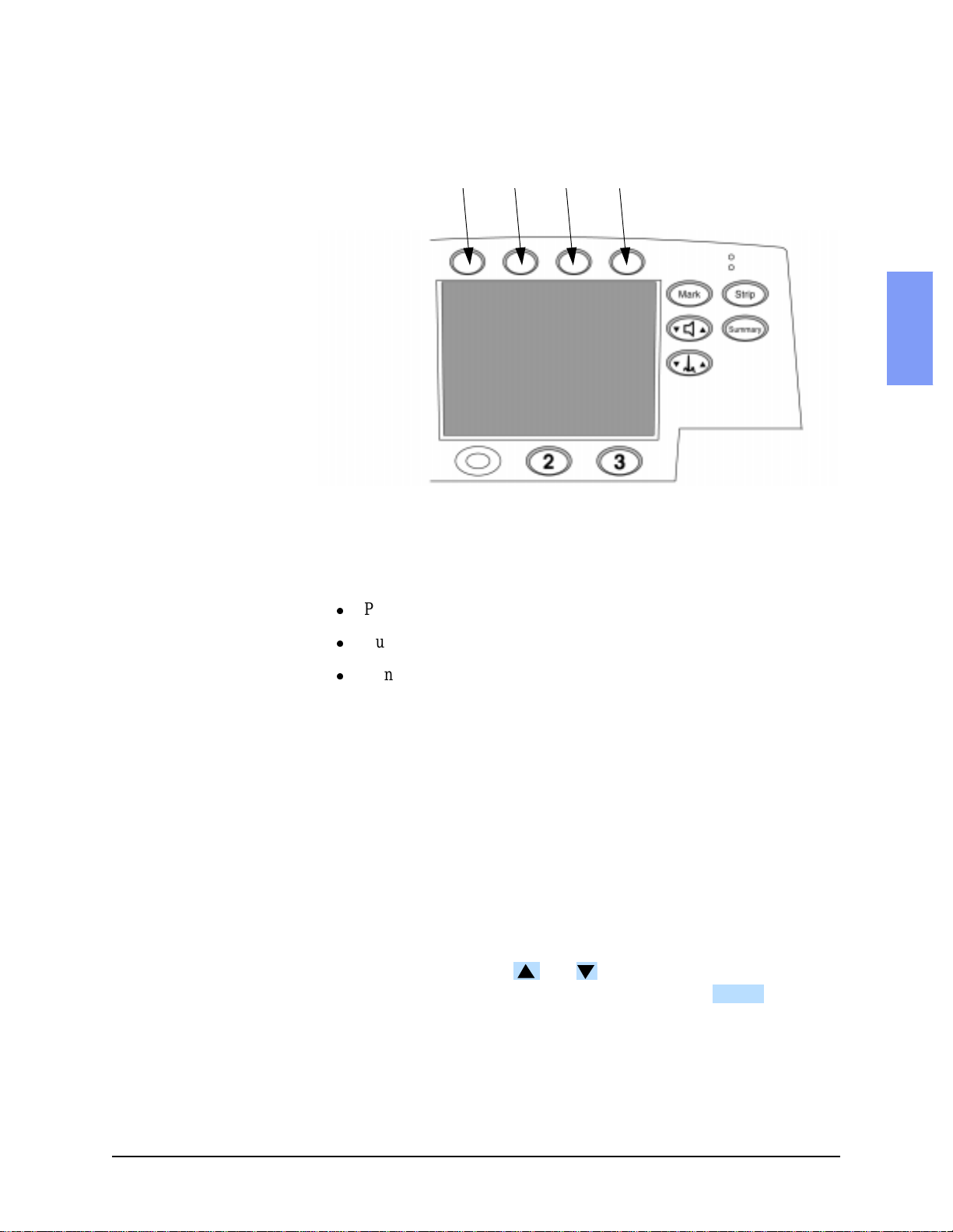
Figure 2-1 Softkey Numbers
Softkeys
4 5 6 7
Configuration and Diagnostic Modes
2
Diagnostic Mode
These instructions describe how to enter Diagnostic Mode. Once in Diagnostic Mode, you can do the following:
l
Print the System Log. See "System Log" on page 2-20.
l
Run the Extended Self Test. See "Extended Self Test" on page 2-22.
l
Run other Diagnostic Tests. See "Diagnostic Tests" on page 2-19.
1. Power off.
Make sure the unit’s power is off.
2. Enter Diagnostic Mode.
Press softkeys 4 and 6 at the same time, and hold them down while turning the power on. See Figure 2-1 for softkey numbering.
3. Wait for the unit to initialize.
This may take several seconds. The unit is ready to proceed when the
screen cursor responds to softkey inputs.
4. Select the desired test or function.
To select a test, press the and softkeys to move up or down the
list until the desir ed te st is h ighli ghted. Then p ress the softkey to
start that test.
ENTER
5. Exit Diagnostic Mode.
To exit Diagnostic Mode, turn the unit off.
M4735A Service Manual 2-11
Page 26

The Software Su pport Tool
The Software Support Tool
The Software Support Tool (M4735-87890) allows field service personnel to
perform 2 tasks: 1) to enable the SpO
number. These tasks need to be performed under the following circumstances:
l
The Control PCA has been replaced.
The Control PCA contains all the operating software, configured
for the installed hardware. It also contains the unit’s serial numbe r,
which was programmed in during manufacturing.
The new Control PCA must be programmed to recognize the
hardware installed in this unit, and to contain that unit’s
serial number.
l
The unit has received an upgrade adding the SpO2 capability.
The added hardware will not be automatically recognized. The
Control PCA must be programmed to recognize the new hardware
installed.
option, and 2) to program in the serial
2
Using the Support Tool
1. Prepare the unit.
a. Have unit power off, and have either a fresh battery installed or the
AC power cord plugged in.
b. Insert the Support Tool data card into the unit.
c. Turn unit power on.
2. Follow the screen prompts.
a. Select whether SpO
b. Program in the unit’s serial number.
l
If this is an Sp O2 upgrade, the serial number should already be
present. In this case, verify it against the factory-applied label on
the bottom of the case.
l
If this is a Control PCA replacement, program in the serial number found on the factory-applied label on the bottom of the case
using the softkeys as i nstructe d on the screen. Be sure to program
it in accurately, as the serial number is used for all repair history
tracking.
hardware is installed or not as appropriate.
2
c. Check all the displayed information carefully before proceeding.
l
If the displayed information is correct, follow the screen prompts
to save the configuration.
2-12 Performance Verification and Safety Tests
Page 27

The Software Support Tool
l
If any of the information is incorrect, follow the prompts to NOT
save the configuration, then start over by powering the unit off,
then back on.
3. Turn off the power and remove the Data Card.
4. Check the customer configuration.
a. Turn the unit back on and enter Configuration Mode (see "Configura-
tion Mode" on page 2-10).
b. Print the configuration and check it against the printout from before
the servici ng began. Reset the configuration (or load it from a Data
Card) as needed.
5. Verify performance.
Perform Performance Verification Testing as described in "Performance
Verification and Safety Tests" starting on page 2-1.
2
M4735A Service Manual 2-13
Page 28

Performance Verification
Performance Verificatio n
This section gives instructions for running Performance Verification tests on
the M4735A. The tests are seque nced to check more basic fu nctions fi rst, and
then build on that to check more complex functions. We recommend you
perform these tests in this sequence. If desired, you can make copies of the
Test Results Matrix (page 2-4) and use it to record results.
The Performance Verification tests include:
Section Page
Visual Inspection 2-15
Functional Checks 2-16
Diagnostic Tes ts 2-19
Safety Tests 2-39
Battery Capacity Test 2-40
2-14 Performance Verification and Safety Tests
Page 29

Performance Verification
Visual Inspection
1. Inspect the unit.
Inspect the entire unit, especially paddles, power cord, printer, battery,
cables, and sensors for signs of the following.
l
Wear or damage to paddles, cables, and adapters.
l
Wear or damage to patient cables and associated strain reliefs.
l
Mechanical damage to case, membrane switches, speaker cover,
ambient light sensor cover, display window.
l
Loose or missing hardware.
l
Evidence of liquid spill. Check inside the printer bucket and
clean out any ac cumulation using glove s and an appr oved c leaner.
l
Residue on the therm al printhead.
l
Printer roller wear.
l
Wear or damage to power cord and associated strain relief.
l
Corrosion on connector pins, printer parts, or battery contacts.
2
Pass: Only normal wear, no damage serious enough to inhibit
performance. No corrosion visible.
2. Check the consumables.
Check the ECG electrodes and defibrillator pads for freshness (data code
or expiration date) and condition.
Pass: Electrodes and pads are within their expiration date and
appear usable. Packaging is unopened and shows no tears or punctures.
No corrosion visible on connector sockets, electrodes, or pads.
M4735A Service Manual 2-15
Page 30

Performance Verification
Functional Checks
The following functional checks exercise the basic functions of the defibrilla-
tor/monitor. They are intended as a broad check of the unit’s performance,
and are designed to complement (not replace) the Diagnostic Tests described
later.
If all elements of a test pass, record that test as a P A SS and re tu rn to the main
diagnostic menu by pressing . If there is any failure, begin trouble-
shooting and repairing as needed. See "Troubleshooting" on page 3-1.
The Functional Checks include:
Check Page
ECG Functional Checks 2-16
Shock Advisory Functional Check 2-17
MAIN
Synchronized Cardiovers ion Funct ional
Check
Sp02 Functional Check 2-18
2-18
ECG Functional Checks
This section describes how to check the oper ation of the ECG func tions. Each
of the ECG checks assumes the unit and the simulator are still set up as they
were at the end of the previous ECG check.
To check ECG display and Heart Rate (HR) functions:
1. Set up the simulator.
a. Connect the ECG simulator to both the Pads input and the 3- or
5-lead ECG cable.
b. Set the simula tor for normal sinus rhythm (NSR), 1mV amp litude, at
some nominal rate (e.g., 60 bpm).
2. Set up the M4735A.
Set the M4735A to Manual operating mode (not Diagnostic Mode).
3. Check the displayed ECG.
Using the softkey, verify that the display shows a normal
ECG with a clean baseline for both Pads and Lead II.
LEAD SELECT
4. Check the Heart Rate (HR).
Verify that the Heart Rate (HR) displayed is correct.
5. Check Leads Off.
a. Disconnect the ECG simulator from the pads cable and ver ify that the
display shows a das hed li ne in pla ce of the wavefo rm and t hat the u nit
both alarms and gives the Pads Off message
b. If using a 5-lead ECG cabl e, set the unit to monitor from th e V lead.
2-16 Performance Verification and Safety Tests
Page 31

Performance Verification
ANALY ZE
ANALY ZE
c. Disconnect each of the ECG leads f rom the simulator one at a time,
and verify that the display shows a dashed line in place of the waveform and that the unit both alarms and gives the
To check ECG printing functions:
6. Reconnect the simulator.
Leads Off
message.
Connect the simulator to the M4735A as described in step 1 above.
7. Print a strip.
a. Print a strip; verify that it shows a normal ECG with a clea n baseline .
b. Verify that th e date, t ime, an d configur atio n inform ation p rinte d at the
top of the strip is correc t.
Shock Advisory Functional Check
This section describes how to check the Shock Advisory function.
1. Set up the simulator.
a. Connect the ECG simulator to the pads cable.
b. Set the simula tor for normal sinus rhythm (NSR), 1mV amp litude, at
some nominal rate (e.g., 60 bpm).
2
2. Set up the M4735A.
Set the M4735A to AED Mode.
3. Check Shock Advisory with NSR.
a. Press .
b. Verify that the defibrillator responds with
4. Check Shock Advisory with Asystole.
a. Set the simula tor to Asystole (or turn the simulator off) and press
ANALY ZE
No Shock Advised
.
.
b. Verify that the defibrillator still responds with
5. Check Shock Advisory with VF.
a. Set the simulator to VF (Ventricular Fibrillation) and press
No Shock Advised
.
.
b. Verify that the defibrillator responds with Shock Advised and charges
up to 150J. If the unit is configured to do so, verify that it automatically prints a strip of the event.
WA RN I NG Do not discharge the stored energy unless you are certain the simulator contains a
50 ohm test load.
M4735A Service Manual 2-17
Page 32

Performance Verification
c. If the simulator contains a 50 ohm test load, discharge the stored
energy into th e te st load . If i t do es not , or you ar e not sure, wait until
the defibrillator reports
Shock cancelled
before proceeding.
Synchronized Cardioversion Functional Check
This section descri bes how to c heck the sy nchronize d cardiove rsion fu nction.
1. Set up the simulator and the analyzer.
a. Connect the ECG simulator to the ECG cable. Connect the defi br il la -
tor analyzer to the pads cable.
b. Set the simula tor for normal sinus rhythm (NSR), 1mV amp litude, at
some nominal rate (e.g., 60 bpm).
2. Set up the M4735A.
Set the defibrillator to Manual Mode, and press .
3. Check Cardioversion.
a. Verify that sync markers appear on the display, at the peak or on the
falling side of the QRS complex. Adjust the size of the displayed
ECG as needed to view it more clearly.
b. Select an energy of 5 J. Press then press and hold
CHARGE SHOCK
until the shock is delivered (at next QRS).
c. Verify on the defibrillator analyzer that the shock was delivered, and
was 5J ±2J.
d. If the unit is configured to do so, veri fy that it prints a strip with the
correct information on it (waveform, text).
e. Verify on the defibrillator analyzer that the delay between the peak of
the QRS and the delivered shock was <
60 msec.
Sp02 Functional Check
This check only needs to be performed if SpO2 is installed.
1. Connect the sensor.
Attach the SpO
2. Check SpO
a. Activate Manual Mode and press the SpO
b. The SpO
value is less t han 95 %, check that y our f ing er is full y in sert ed in to the
sensor and properly positioned.
transducer to your finger and connect it to the M4735A.
2
.
2
softkey to turn SpO2 on.
2
value displayed should be in the range of 95-100%. If the
2
2-18 Performance Verification and Safety Tests
Page 33

Performance Verification
Diagnostic Tests
The M4735A includes an extensive set of Diagnostic Tests, which test the
major hardware components of the defibrillator.
The Diagnostic Tests include:
Test Page
System Log 2-20
Extended Self Test 2-22
User Interface Tests 2-25
ECG Tests 2-29
Pacing Test 2-33
Defibrillator Test (AC Power At 200 J) 2-35
Defibrillator Test (Battery Power At 200 J ) 2-36
Defibrillator Disarm Test 2-38
2
M4735A Service Manual 2-19
Page 34

Performance Verification
System Log
The System Log includes the unit’s serial number, hardware configuration,
and a listing of error codes. The System Log should be printed each time a
Performance Verification Test is run.
1. Enter Diagnostic Mode.
See "Diagnostic Mode" on page 2-11.
2. Print the System Log.
a. Select
b. The printer will prin t the System Log stri p. See " Sample Sys tem Log
Print Log
and press .
ENTER
Printout" on page 2-21.
3. Check the System Log.
a. Check hardware and options.
l
Check the printout to veri fy the print ed result s are consis tent with
the hardware in place. Check options installed (SpO
, pacing)
2
and the unit’s serial number (on the bottom of the case).
l
If the printout is not c o rr ec t, i nve st igate and resolve the source of
the mismatch. Then reset t he hardwar e options and ser ial number
as needed using the Support Software Tool. See "The Software
Support Tool" on page 2-12.
b. Check for M4735A errors.
If there are device errors reported in the System Log:
l
Check the time and date stamps to see if they are recent errors or
not.
l
Consult Table 3-2 "Error Codes" on page 3-10 to identify the
errors.
l
Begin troubleshootin g as nee ded (See "Troubleshooting" on page
3-1. )
2-20 Performance Verification and Safety Tests
Page 35

Figure 2-2 Sample System Log Printout
M4735A SYSTEM LOG
Firmware Versions Error Codes
Main: 06 90007 18:33 19 MAY 2000
DSP: 02
196: 06.00
Performance Verification
Key: 01
SpO2: 02.42 01.04
Language: English
Serial Number: US01000241
Options: Pacer SpO2
Shocks: 2
2
M4735A Service Manual 2-21
Page 36

Performance Verification
Extended Self Test
The Extended Self Test checks that all internal processors are operating and
communicating with each other.
If all results are as described, the unit passes this test. Return to the main
Diagnostic Test menu by pressing .
If there is any fa ilure, be gin troubl eshootin g and repa iring th e unit as needed.
See "Troubleshooting" on page 3-1, and Table 3-6 "Extended Self Test Failures" on page 3-17.
NOTE Be sure the printer has paper and that the printer door is closed. No paper or
an open door will generate an erroneous
1. Connect the test load to the pads cable.
2. Access the Diagnostic Test menu.
See "Diagnostic Mode" on page 2-11.
3. Run the test.
MAIN
Fail
in the
Timebase
test.
Extended Self Test
Select
and press . The printout should appear
ENTER
similar to Figure 2-3.
Figure 2-3 Sample Extended Self Test Printout
M4735A EXTENDED SELF TEST 18:48 5/19/2000
RAM: Pass
ROM: Pass
System: Pass
Data Card: Not Tested
CODEC: Pass
IRDA: Not Tested
Timebase: Pass
Defib: Pass
FE: Pass
SpO2: Pass
Pacer: Pass
2-22 Performance Verification and Safety Tests
Page 37

4. Check the results.
a. Check the time and date.
l
Check the printout to verify that the time an d date are cor rect.
l
If they are not, reset them using the Configuration Mode. See
"Configuration Mode" on page 2-10.
b. Check the test results.
The results of the following tests will appear on the display and
on the printout:
l
RAM
Tests the Read Only Memory (ROM).
l
ROM
Tests the Random Access Memory (RAM).
l
System
Tests the integrity of the core processing system and checks
the Lithium backup battery.
Performance Verification
2
l
l
l
l
Data Card
The Data Card test writes a small file to the data card,
reads it back and checks it, then erases that file. If no
Data Card is present, the test result will be
Not Tested
.
CODEC
The processor turns on the CODEC (coding/decoding) chip
(used for voice prompts), and gets an acknowledgement
that it’s ready to receive data. It does not give the CODEC
actual data to process.
IRDA
Tests the infrared communications port. If no active
infrared device is within range, the test result will be
Not Tested
Timebase
The Timebase test compares the Real Time clock to the System
clock to check for discrepancies. It does not test the SpO
or the Biphasic clock.
clock
2
.
M4735A Service Manual 2-23
Page 38

Performance Verification
l
DEFIB
The Defib test charges the defibrillator capacit or and then
disarms it. It does not deliver the energy outside the unit.
The pads cable and test load must be connected for the test
to run; otherwise the test result will be
l
FE
Not Tested.
The Front End (FE) test checks that the main processor is
communicating with the Digita l Signal Proces sor (DSP), and tha t
the DSP is communicating with both ECG front ends (pads and
leads). It does not test the quality of the ECG measurement.
l
SP02
(if SpO
option installed)
2
This tests that communicati on with the SpO
PCA is working. It
2
does this by reading the software revision back from the PCA.
It does not test the quality of the SpO
l
Pacer
(if Pacing option installed)
measurement.
2
The Pacer test has the Pacer deliver current into the test box , and
measures that the current delivered was what was expected. The
pads cable and test load must be connected for the test to run;
otherwise the test result will be
Not Tested.
2-24 Performance Verification and Safety Tests
Page 39

Performance Verification
User Interface Tests
The User Interface Tests exercise the functions that interact with the user.
Each of the User Interface t ests as sumes the unit an d the simulat or are stil l set
up as they were at the end of the previous User Interface check.
If all results are as described, the unit passes that test. Return to the main
Diagnostic Test menu by pressing .
If there is any fa ilure, be gin troubl eshootin g and repa iring th e unit as needed.
See "Troubleshooting" on page 3-1 and the following specific tables:
l
Table 3-11 "Operational Problems - Printer" on page 3-25.
l
Table 3-12 "Operational Problems - Display" on page 3-26.
l
Table 3-13 "Operational Problems - Audio Tones/Voice Prompts" on
page 3-27.
l
Table 3-14 "Operational Problems - Keys" on page 3-28.
To test the Controls (keys):
1. Access the Diagnostic Test menu.
MAIN
2
See "Diagnostic Mode" on page 2-11.
2. Start the Controls Test.
Controls Test
Select
and press . The screen will display a map of
ENTER
the front panel keys.
3. Test the softkeys.
Press each of the numbered softke ys in t urn. See Fi gure 2- 1 on page 2-11
for numbering of softkey s. Each softk ey number on the display sh ould be
highlighted each time that key is pressed.
Don’t press Softkey #4 at this time. This will return you to t he
MAIN
Main diagnostic mode menu.
4. Test the ECG and Audio keys.
Test each of the ECG Size and Vo l u m e keys. See Figure 2-1 on page 2-11
for location of th ese keys.Each key should show a highlighted ("p lus ")
+
when the up arrow on the key is pressed, and show a highlighted
("minus") when the down arrow is pressed.
5. Test the printer keys.
Test each of the printer control keys (Strip, Summary, and Mark). Each
corresponding label on the display should be highlighted each time that
key is pressed.
-
6. Test the pacing keys.
Test each of the Pacing keys. The displayed labels for Pacer, Start/Stop
and Mode should be highlighted each time that key is pressed. The dis-
M4735A Service Manual 2-25
Page 40

Performance Verification
played labels for
Rate
and
Output
should show a highlighted ("plus")
+
when the up arrow on the key is pressed, and show a highlighted
("minus") when the down arrow is pressed.
7. End the test.
Press Softkey #4 to return to the Main diagnostic mode menu.
To test the display:
1. Run the Display Test.
Display Test
Select
MAIN
and press .
ENTER
The display should turn completely light, then completely dark, then a
light vertical bar should scroll across the screen from left to right.
2. Test the LEDs.
The display will show a softkey label. Press thi s s oft key and
TEST LEDs
verify that the indicators in the Main and Pacing keypads each light in
turn. The
3. End the test.
AC Power
Press Softkey #4 to return to the Main diagnostic mode menu.
and
MAIN
Batt Charge
LEDs will not
light as part of this test.
-
To test the audio output:
1. Start the Audio Test.
Audio Test
Select
and press . The screen will d isp lay t he
ENTER
menu.
2. Select and run the desired test.
a. Press the and softkeys to move up or down the list to select
the desired test. Then press to begin that test.
Check the
Shutdown Warning
ENTER
and the
Voice Prompt
; the
other responses are given for reference. The results should
be as described below.
Press to end that test and return to the main
CANCEL
audio test menu.
l
Message Alert - A repeating series of 3 short tones, followed by a
pause.
l
Heart Rate Alarm - 1 sustained tone of moderately high pitch.
l
Charge Done Tone - 1 sustained tone of lower pitch than the Heart
Rate Alarm.
l
Auto Disarm Warning - A repeating series of 1 short tone and a
pause.
Audio Test
2-26 Performance Verification and Safety Tests
Page 41

l
CANCEL
Shutdown Warning
high/low pitch.
l
Voice Prompt
3. End the test.
Performance Verification
- A repeating series of tones of alternating
- Voice should be clear and understandable.
Press Softkey #4 to return to the Main diagnostic mode menu.
MAIN
To test the printer:
1. Start the Printer Test.
a. Select
2. Check the pri nt quality.
a. Verify that the test pa tterns on the strip are as indicated in
Printer Test
and press .
ENTER
Figure 2-4.
b. Check for white lines (printhead elements stuck off) or black lines
(printhead elements stuck on).
c. Check area "A" for stray ma rks or lines.
d. The area of Figure 2 -4 la beled "C" co ntain s pri ntouts of al l cha racte rs
and symbols. Verify that they are readable.
3. Stop the printout.
Press to end the test and return to the main Diagnostic Test
menu.
2
4. Verify the print speed.
Measure between the long tick marks (B in Figure 2-4) to verify paper
speed. Distance should be 25mm ± 5% (±1.25 mm).
5. Check the printer status detection.
a. Open the printer door and press the
Strip
key. The unit should sound
a series of 3 tones indicating a printer problem.
b. Take out the paper, close the door, and press the Strip key. The unit
should sound a series of 3 tones indicating a printer problem.
M4735A Service Manual 2-27
Page 42

Performance Verification
Diagonal lines
Vertical bars
Diamonds
Figure 2-4 Printer Test Output
2-28 Performance Verification and Safety Tests
Page 43

Performance Verification
ECG Tests
These instructions describe how to test the ECG functions.
Each of the ECG tests assumes the unit and the simulator are still set up as
they were at the end of the previous ECG test.
If all results are as desc ribed, the unit p asses that portion of the test. Return to
the main Diagnostic Test menu by pressing .
If there is any fa ilure, be gin troubl eshootin g and repa iring th e unit as needed.
See "Troubleshooting" on page 3-1 and Table 3-7 "Operational Problems ECG Monitoring (Pads or Leads)" on page 3-18.
1. Start the test.
a. Access the Diagnostic Test menu as described in "Diagnostic Mode"
on page 2-11.
MAIN
2
b. Select
c. The display should look similar to Figure 2-5:
Figure 2-5 ECG Test Display
ECG Test
and press .
ENTER
MAIN ENTER
ECG TEST
Selected Lead: Lead I
AC Line Filter: 60 Hz On
Leads FE Status: Good
Pads FE Status: Good
DSP Status: Good
DC Offset: xxxx
Pea k to Peak:
Diagnostic: 1050
Monitor: 1090
PCI: 51 Off
2.
Check the se ttings.
a. AC Line Filter
The AC Line Filter should be set to the correct frequency
for your area.
If the setting is incorrect, access the Configuration Mode and correct
it. See "Configuration Mode" on page 2-10.
M4735A Service Manual 2-29
Page 44

Performance Verification
b. Selected Lead
This setting does not matter at this point. It will be changed later.
3. Change the settings as needed.
a. To temporarily change the settings of
Selected lead
AC Line filter
or
,
press the and softkeys to highlight the parameter, then press
(and release) to select it.
NOTE The available choices for Selected Lead will depend on whether the unit is
ENTER
configured for 3-lead or 5-lead ECG monitoring.
b. After a few seconds the highlighted selection will begin to blink, and
the and softkeys will allow you change the selection to
another of the values available. When the value you want is dis-
played, press to set that value.
NOTE These changes are onl y tempo rary, and will not overr ide the c onfigu rati on set
ENTER
in Configuration Mode.
4. Check the ECG Status messages.
The 3 status messages (
The
Leads FE
test checks that communication is working between
l
Lead FE, Pad FE, DSP
) should all be
GOOD
.
the Leads Front End ( FE) and the Digital Signal Processor (DSP) .
The
Pads FE
test checks that communication is working between
l
the Pads FE and the DSP.
The
DSP
test checks that communication is working between the
l
DSP and the re st of the monitor.
5. DC Offset.
This test is for manufacturing use only and should be ignored.
6. Test the ECG amplifier.
These tests measure both the gain and the noise of the two ECG amplifiers (Leads and Pads). Both use the Peak to Peak reading.
The Peak to Peak reading measures the peak to peak amplitude of the sig-
nal appearing on the selected ECG input. If the simulator’s calibrated
output is 1.0 mV, then the Peak to Peak reading should be 1000 ± 10%
(±100) for both Monitor and Diagnostic. If the simulator output is cali-
brated to some other value, the displayed value should be (1000 x simulator output) ±10%.
NOTE The diagnostic frequency response is only available when using the ECG
Leads input. When the unit is set to Pads, the display will indicate dashes
(-----) for the Diagnostic Peak-to Peak value.
2-30 Performance Verification and Safety Tests
Page 45

Performance Verification
a. Perform the ampl ifier gain test:
1. Connect the ECG simulator to the pads cable. Set the simulator
output for sine wave, 2 Hz or 10 Hz, 1 mV peak-to-peak.
2. Following the instructions under Step 3 on page 2-30 for chang-
ing settings, set
Selected lead
to
Pads
. Only the
Monitor
frequency
response will be available.
3. Wait for the displayed value under
4. The displayed value should be 1000 ±10% (± 100). Record t his as
Monitor
to stabilize.
"aaaa".
5. Connect the ECG simulator to the ECG leads cable.
6. Following the instructions under Step 3 on page 2-30 for chang-
ing settings, set
7. Wait for the displayed value under
8. The displayed value should be 1000 ±10% (± 100). Record t his as
Selected lead
to
Lead II
Diagnostic
.
to stabilize.
"bbbb".
b. Perform the ampl ifier noise test:
1. Turn the simul ator of f. Leave it conn ected t o the ECG cable, and
Selected lead
leave
2. Wait for the displayed value under
3. The displayed value should be 0 ± 30 uV. Record this as "cc".
set to
Lead II
.
Diagnostic
to stabilize.
If the unit exhibi ts more th an 30 uV of noise, try repositi oning the
cable or unit to minimize external interference. Also try various
combinations of having the ECG simulator turned on or off, and
(if applicable) whether the simulator is plugged into the AC
mains. Refer to C hapter 7 for more information about reducing
electromagnetic int er fe rence.
2
4. Following the instructions under Step 3 on page 2-30 for chang-
ing settings, set Selected lead to Pads.
5. Connect the simulator to the pads cable.
6. Wait for the displayed value under Monitor to stabiliz e.
7. The displayed value should be 0 ± 30 uV. Record this as "dd".
M4735A Service Manual 2-31
Page 46

Performance Verification
7. Test the PCI function.
This test checks the PCI (Patient Contact Indicator) function. The PCI
measurement is used to detect Pads Off and Paddles Off, and to light the
Patient Contact Indicator LEDs on PCI-equipped paddle sets. It is an
approximate measurement only - the impedance value used to adjust the
defibrillation wave for m is a se par at e meas ure me nt , made dur ing del ive ry
of the shock. See "Theory of Operation" beginning on page 6-1 for more
details.
a. Connect a set of external paddles to the M4735A.
b. If the PCI setting is
On
, turn it
Off
now by pressing the Volume Up and
Down arrow keys simultaneously. (See Figure 2-1 on page 2-11.)
c. Remove the paddles fr om their hold ers and hold them firmly togeth er ,
face to face (metal-to-metal). Be sure the paddles clean and are making good contact with one another
d. Turn the PCI setting
On
by pressing the Volume Up and Down arrow
keys simultaneously. (See Figure 2-1 on page 2-11.) The displayed
PCI value should now read 0.
e. Place the paddles back i n the ir h olders . Be s ure t he met al c ontac t cl ip
in the holder is clean and makes good contact with the face of the
paddle.
f. The PCI measurement should now read 50 ohms ±30 ohms. Record
this as "ee".
g. Remove the paddles from the holders and hold them apart. The PCI
measurement should read > 1250 ohms (full scale). Record this
as "ffff".
2-32 Performance Verification and Safety Tests
Page 47

Performance Verification
Pacing Test
These instructions describe how to test the pacing function. This test only
needs to be run if the Pacing option is installed.
If all results are as described, the unit passes the test. Return to the main
Diagnostic Test menu by pressing .
If there is any fa ilure, be gin troubl eshootin g and repa iring th e unit as needed.
See "Troubleshooting" on page 3-1 and Table 3-10 "Operational Problems Pacing" on page 3-24.
1. Set up the test.
a. Connect the defibrillator to the Pacer tester.
MAIN
2
b. From the Diagnostic Menu, select
display should look similar to Figure 2-6.
Figure 2-6 Pacer Test Display
MAIN
PACER TEST
Pacer Status: Off
Selected Rate: 70
Selected Output: 30
Delivered mA: 0
Pacer Test
and press . The
ENTER
2. Begin Pacing.
a. Press . The LED to the left of the button will illuminate.
The screen display of Pacer Status will change to Stopped.
b. Press . Pacer Status will change to Pacing, and pacing
6WDUW
6WRS
will begin at the default settings of 70 beats per m inute (bpm) and 30
mA.
M4735A Service Manual 2-33
Page 48

Performance Verification
3. Check the default output.
a. The Pacer should be d elive ring a cur rent of 3 0mA ±5mA. Record the
delivered current indicated by the Pacer tester as "aa".
b. The display on th e M4735A should read the delivered current as mea-
sured by the Pacer tester ("aa") ±5 mA.
4. Test the maximum output.
a. Using the button, increase the rate to 180 bpm.
b. Using the button, increase the output to 200 mA.
c. The Pacer should be delivering a current of 200mA ±20mA. Record
Rate
Output
the deliver ed current i ndicated by the Pacer tester as "bbb".
d. The display on th e M4735A should read the delivered current as mea-
sured by the Pacer tester ("bb") ±20 mA.
5. End the test.
Turn off Pacing by pressing the button.
2-34 Performance Verification and Safety Tests
Page 49

Performance Verification
Defibrillator Test (AC Power At 200 J)
These instructions describe how to test the defibrillation function when powered only by AC power (no battery installed).
If all results are as described, the unit passes the test. Return to the main
Diagnostic Test menu by pressing .
If there is any fa ilure, be gin troubl eshootin g and repa iring th e unit as needed.
See "Troubleshooting" on page 3-1 and Table 3-9 "Operational Problems Defibrillation and Synchronized Cardioversion" on page 3-21.
1. Set up the test.
a. Turn defi br il la tor off and remove the battery. Connect the AC Power
cord.
b. Connect the defibrillator analyzer to the pads cable. Set the analyzer
to measure delivered energy. If needed, reset the analyzer’s display to
read 0.
c. Turn the defibrillator on, and from the Diagnostic M enu, Select the
Defib Meas Test
and press .
MAIN
ENTER
2
2. Deliver a 200J shock.
a. Use the
b. Press the softkey to charge the defibrillator.
c. Press
3. Check the analyzer readings.
Energy Select
CHARGE
.
SHOCK
control to select 200J.
Read the delivered energy indicated by the defibrillator analyzer. It
should be 200J ±15% (±30J). Record as "aaa".
4. Check the values displayed by the M4735A.
The results displayed by the M4735A should be as follows:
Available Energy: Not recorded - failure if >0.
ms to Charge: <
15000 (Record as "bbbbb")
Delivered Energy: Actual delivered energy ("aaa") ±7%(Record as "ccc")
Impedance: 42 to 57 ohms (Record as "dd")
Peak Current: Ignore. Derived from same measurements as delivered
energy and impedance
Defib Errors: Not recorded - failure if any reported.
Shock Counter: Disregard.
M4735A Service Manual 2-35
Page 50

Performance Verification
Defibrillator Test (Battery Power At 200 J)
These instructions describe how to test the defibrillation function when powered only by a fully charged battery, with no AC power connected.
If all results are as described, the unit passes the test. Return to the main
Diagnostic Test menu by pressing . If there is any failure, begin trou-
bleshooting and repairing the unit as needed. See "Troubleshooting" on
page 3-1 and Table 3-9 "Operational Problems - Defibrillation and Synchronized Cardioversion" on page 3-21.
1. Set up the test.
a. Turn the defibrillator off. Insert the battery and disconnect the AC
Power cord.
b. Connect the defibrillator analyzer to the pads cable. Set the analyzer
to measure delivered energy. If needed, reset the analyzer’s display to
read 0.
c. Turn the defibrillator on, and from the Diagnostic M enu, Select the
Defib Meas Test
and press .
MAIN
ENTER
2. Deliver a 200J shock.
a. Use the
b. Press the softkey to charge the defibrillator.
c. Press
3. Check the analyzer readings.
Energy Select
CHARGE
.
SHOCK
control to select 200J.
Read the delivered energy indicated by the defibrillator analyzer. It
should be 200J ±15% (±30J). Record as "aaa".
4. Check the values displayed by the M4735A.
The results displayed by the M4735A should be as follows:
Available Energy: Not recorded - failure if >0.
ms to Charge: <
3000 (Record as "bbbb")
Delivered Energy: Actual delivered energy ("aaa") ±7%(Record as "ccc")
Impedance: 42 to 57 ohms (Record as "dd")
Peak Current: Ignore. Derived from same measurements as delivered
energy and impedance
Defib Errors: Not recorded - failure if any reported.
2-36 Performance Verification and Safety Tests
Page 51

Performance Verification
NOTE If the "
verify that the battery is fully charged. If it is, the battery may simply be old.
The 3000 ms specification is defined for a new, freshly charged M3516A battery. Replace the battery with one that is new and fully charged, and repeat
the test.
ms to Charge
" measurement is too high (unit takes too long to charge),
2
M4735A Service Manual 2-37
Page 52

Performance Verification
Defibrillator Disarm Test
These instructions describe how to test the disarm function.
If all results are as described, the unit passes the test. Return to the main
Diagnostic Test menu by pressing . If there is any failure, begin troubleshooting and repairing the unit as needed. See "Troubleshooting" on
page 3-1.
1. Set up the test.
a. Turn the defibrillator off. Insert the battery and connect the AC
Power cord.
b. Connect the defibrillator analyzer to the pads cable. Set the analyzer
to measure delivered energy. If needed, reset the analyzer’s display to
read 0.
c. Turn the defibrillator on, and from the Diagnostic M enu, Select the
Defib Meas Test
2. Charge and Disarm a 200J shock.
and press .
MAIN
ENTER
a. Use the
b. Press the softkey to charge the defibrillator.
c. Press
3. Check the analyzer readings.
Energy Select
CHARGE
.
DISARM
control to select 200J.
Read the delivered energy indicated by the defibrillator analyzer. It
should be 0J or be blank.
4. Check the values displayed by the M4735A.
The results displayed by the M4735A should be as follows:
Available Energy Not recorded - failure if >0.
Msec to charge Ignore - tested earlier
Delivered energy Blank
Impedance Blank
Peak current Blank
Defib errors Not recorded - failure if any reported.
2-38 Performance Verification and Safety Tests
Page 53

Performance Verification
Safety Tests
This section covers tests of the defibrillator’s electrical safety.
Using the procedures called out by the manufacturer of the analyzer in use,
measure and record the following data. Only test at the AC Mains (line) voltage used in the customer’s facility - there is no need to test both 120VAC and
240VAC. Also, test both Normal and Reverse Polarity line connections, and
record the worst case value.
Earth Leakage
l
Normal Condition - < 500 uA (< 300 uA for UL)
Record as "aaa".
l
Single Fault Condition - < 1000 uA
Record as "bbbb".
Patient Lead Leakage
Test both Leads (C) and paddles/pads (B) inputs.
2
l
Source (Normal Condition) - < 10 uA (C), < 100 uA (B)
Record as "ccc".
l
Source (Single Fault Condition) - < 50 uA (C), < 500 uA (B)
Record as "ddd".
l
With Mains on Applied Part (Single Fault Condition) - < 50 uA (C),
<
5000 uA (B)
Record as "eeee".
l
Auxiliary (Normal Condition) - < 10 uA (C), < 100 uA (B)
Record as "fff".
l
Auxiliary (Single Fault Condition) - < 50 uA (C), < 500 uA (B)
Record as "ggg".
M4735A Service Manual 2-39
Page 54

Performance Verification
Battery Capacity Test
The Battery Capacity Test is not part of t he routin e Performan ce Verification.
It is included here for reference only.
To perform a Battery Capacity Test:
1. Turn the M4735A off.
2. Label the unit.
Place a "Test in Progress" label on t he unit to in dicat e to others that it m ay
not be used.
3. Insert a charged battery.
If an AC power cord is connected, unplug it now.
4. Run the test.
a. While pressing , turn power on to start the test.
b. Allow the test to pr oceed t o com pleti on. The test ta kes app roximat ely
Mark
three hours and is complete when test results print out and the device
turns itself off.
5. Check results.
Review the test results and take the appropriate action, as follows:
Table 2-3 Battery Capacity Test Results
If Then
Elapsed Time >
and
Low Battery Time > 10 minutes
Elapsed Time < 2.5 hours
or
Low Battery Time < 10 minutes
2.5 hours
1. The battery passed the test.
2. Record "pass CT" and the date on
the label on the bottom of the battery.
3. Recharge the battery before use.
1. The battery failed the test.
2. Record "fail CT" and the date on the
label on the bottom of the battery.
3. Discard the battery appropriately.
2-40 Performance Verification and Safety Tests
Page 55

3 Troubleshooting
Overview
This chapter provides information for troubleshooting problems with the
M4735A.
Chapter Contents
The major sections of this ch apter are as fo llows:
Section Page
Repair Philosophy 3-1
Equipment Required 3-1
Troubleshooting and Repair Methodology 3-2
Troubleshooting Tables 3-6
Calling for Service 3-31
Repair Philosophy
The repair philosophy of the M4735A is subassembly replacement. Examples of subassemblies are the printer, the Control PCA, and selected connectors and other items. Repairs th at involve repl acing individu al components on
a PCA are not supported.
CAUTION Individual component replacement should not be attempted outside of a fac-
tory authorized repair facility. Component level repair is extremely difficult
due to the extensive use of surface mount technology and the high parts-density on the circuit boards. Unauthorized component replacement can impair
performance of the M4735A.
3
Equipment Required
Trouble shooti ng requi res t he same t est equi pment as does Performanc e Verification. See "Test Equipment" on page 2-8.
3-1
6/29/00
Page 56

Troubleshooting and Repair Methodology
Troubleshooting and Repair Methodology
We recommend you follow the methodology described below to isolate and
repair problems with the M 4735A:
Section Page
Methodology Overvie w 3-2
Initial Assessment 3-3
Diagnosing External Failures 3-4
Diagnosing Internal Failures 3-5
Methodology Overview
Interview the User
If possible , talk directly with the u ser who repo rted the problem. Identify
what they were doing when the problem occurred, and exactly what happened. What was on the display? What tones or voice prompts were heard?
Were there operational problems?
Identify the Problem
First, evaluate the unit’s condition using the steps in "Initial Assessment" on
page 3-3. Then use "Diagnosing External Failures" on page 3-4 to identify
problems that can be resolved without further troubleshooting. Finally, if
needed use "Diagnosing Internal Failures" on page 3-5 to isolate the problem
to a particular subassembly.
If no trouble is found, proceed to the "Performance Verification and Safety
Tests" chapter for instructions on tests to run.
Perform the Repair
Follow the procedures in the "Removal and Replacement" chapter to replace
any defective subassemblies.
When the repair is complete, it is good practice to check the repair by attempting to reproduce the specific problem found. It is also advisable to print the
System Log again to check that no errors have been logged after the repair.
Test the Unit
Use the procedures found in the "Performance Verification and Safety Tests"
chapter to verify that the unit is operating properly overall. Be sure the testing
performed is appropriate for the level of repair.
3-2 Troubleshooting
Page 57

Initial Assessment
Initial Assessment
Use the following steps to begin isolating the problem.
Attempt Power Up
Assess the unit’s overall condition by performing the following steps.
1. Disconnect the AC Power cord (if connected).
2. Insert a fully charged battery into the unit.
3. If the unit is used with a Data Card, insert a new, empty M3510A Data
Card into the unit.
4. Attempt to power up the unit by turning the Energy Select Switch to
Manual On
either
Evaluate the Response
The unit will respond in one of the following 3 ways:
No response
IF The unit emits no sounds, and no changes are visible on
the display.
or
AED ON
.
3
THEN Troubleshoot further using Table 3-1 on page 3-8.
("Unit Unresponsive").
Minimal response
IF Unit provides only a slight response, such as a click or chirp
from the speaker, or a change in the brightness or t h e bor der s
of the display.
THEN Replace the Control PCA (see "Removal and Replacement"
on page 4-1).
Return to this section and begin again with
"Attempt Power Up".
Powers Up
IF The unit can generate tones or voice prompts, or display text
or graphics, or respond to keypresses.
THEN Proceed to "Diagnosing External Failures" on page 3-4.
IF The screen is blank except for an error message such as
Defib Failure - Cycle Power.
THEN Proceed to "Diagnosing Internal Failures" on page 3-5.
M4735A Service Manual 3-3
Page 58

Diagnosing External Failures
Diagnosing External Failures
Many times, a problem will be the resul t of exte rnal fa ilur es such as de fecti ve
cables, depleted batteries, or improper operation. Use the steps below to rule
out these external failures before looking for an internal failure in the unit.
Capture the Configuration Data
Store the unit’s configuration data on a Data Card or print out the current configuration, if possible. See "Configuration Mode" on page 2-10.
Print the System Log
Print out the System Log if possible, and use any error codes to help isolate
the problem. See "System Log" on page 2-20.
NOTE The M4735A log of error codes only reports the last 10 errors. If new errors
are created at this stage they may overwrite the existi ng codes and v aluable
clues to the reporte d problem migh t be lost . Therefor e always atte mpt to pr int
the System Log before proceeding.
Rule out external components and improper use
Referring to Table 5-16 for Supplies and Accessorie s, make sure the unit has:
l
An undamaged, fully charged M3516A battery.
l
A new , dry r oll of Agi lent 4045 7C/D printe r paper. Printer paper may
jam if paper is wet. Also, printer may be damaged if wet paper is
allowed to dry while in contact with the printer elements.
l
Cables and sensors which are approved by Agilent and known to be
good. Also make sure that all external cables are fully inserted in
their receptacles.
l
A new, empty Data Card of the correct type (M3510A). Plugging in
the wrong type of card (e.g., a modem card) can cause startup failures.
T o help identify problems whi ch may be ca used by ext ernal compo nents or b y
improper use, refer to:
l
Table 3-3 ("System Messages") and Table 3-4 ("Momentary messages").
l
The individual tables describing Operational Problems associated
with each function (defibrillation, ECG, etc.). See "Troubleshooting
Tables" on page 3-6.
Proceed to Internal Failures
If none of the above resolves the problem, proceed to "Diagnosing Internal
Failures" on page 3-5.
3-4 Troubleshooting
Page 59

Diagnosing Internal Failures
Diagnosing Internal Failures
The following steps will help you isolate an internal failur e to a particular
subassembly.
Capture the Configuration Data
If not already captured, store the unit’s configuration data on a Data Card or
print out the current con fi gur ati on, if possible. See "Configuration Mode" on
page 2-10.
Print the System Log
If not already printed, print out the System Log if possible, and use any error
codes to help isolate the problem. See "System Log" on page 2-20.
NOTE The M4735A log of error codes only reports the last 10 errors. If new errors
are created at this stage they may overwrite the existi ng codes and v aluable
clues to the reporte d problem migh t be lost . Therefor e always atte mpt to pr int
the System Log before proceeding.
3
Run Self Tests
To run the Self Tests, perform the following steps:
1. Enter Diagnostic Mode. See "Diagnostic Mode" on page 2-11.
2. Run the Extended Self Test. See "Extended Self Test" on page 2-22.
3. Run the individual Diagnostic Tests that are applicable to the problem.
Diagnostic Tests are described starting with "User Interface Tests" on
page 2-25.
Use the Troubleshooting Tables
Use the Tables provided starting on page 3-6 to isolate the problem based on
factors such as:
l
Error codes reported in the System Log (Table 3-2, page 3-10).
l
Extended Self Test failures (Table 3-6, page 3-17).
l
Operational problems (starting with Table 3-7 on page 3-18).
M4735A Service Manual 3-5
Page 60

Troubleshooting Tables
Troubleshooting Tables
Tables are provided to cover the troubleshooting topics below.
General Problems Page
Unit Unresponsive 3-8
Error Codes 3-10
System Message s 3-12
Momentary Messages 3-14
Audio Tones 3-16
Extended Self Test Failures 3-17
Operational Problems Page
ECG Monitoring 3-18
SpO2 Monitoring 3-20
Defibrillation and Cardioversion 3-21
Pacing 3-24
Printer 3-25
Display 3-26
Audio 3-27
Keys 3-28
Battery and Charging Circuits 3-29
Data Card 3-30
Using the Tables
The tables provide both Possible Causes and Corrective Actions. Use them
as follows:
l
The Possible Causes are arranged in order of the approximate proba-
bility of their occurrence. Investigate them in the order given.
l
For each Possible Cause, try the Correc tive Act ions listed. If the first
Corrective Action doe s not fix t he pro ble m, try th e ot hers in the order
listed.
l
If none of the Corrective Ac ti ons fixe s the prob le m, then tr y the next
Possible Cau se listed.
NOTE Before replacing any parts, check to see if the cables and flex circuits are
properly connected. See "Servicing Notes" on page 4-1.
3-6 Troubleshooting
Page 61

Troubleshooting Tables
3
M4735A Service Manual 3-7
Page 62

General Problems
General Problems
The folowing tables de scribe ge neral or system-le vel problems. For pro blems
pertaining to a particular operation or function, see "Operational Problems"
on page 3-18.
Unit Unresponsive
Isolate the fault by follow ing the steps in Ta ble 3-1 below.
NOTE Before replacing any parts, check to see if the cables and flex circuits are
properly connected. See "Servicing Notes" on page 4-1.
Table 3-1 Unit Unresponsive
Test Result Possible Causes Corrective Actions
1. Connect AC Power to un it. "AC Power’ indicator
turns GREEN.
’AC Power’ indicator
stays OFF.
2. Turn on Power and
observe unit’s response.
Unit powers up to so me
working state.
Unit still unresponsive. Short or other failure
Normal response. None. Proceed to step 2.
No power in AC outlet.
Power cord defective. Replace power cord.
AC Power Module
failure.
Main fuse open. 1. Replace Main Fuse.
Open in battery wiring.
somewhere in unit.
Restore power.
Replace AC Power Module.
2. Replace Power PCA and
Main Fuse.
1. Check/replace Battery
PCA.
2. Check/replace wiring to
Power PCA.
Disconnect printer and display from Control PCA at
Control PCA. Then proceed to step 3.
3-8 Troubleshooting
Page 63

General Problems
3. Turn on Power and
observe unit’s response.
Unit powers up to so me
working state.
Unit still unresponsive. Short or other failure
Short in printer or display.
somewhere in unit.
Isolate the fault by reconnecting one at a time and
powering up again. Then
replace the display or printer
as needed.
1. Replace Control PCA.
2. Replace Power PCA.
3. Replace Parameter PCA.
If all above unsuccessful,
return unit for bench repair.
3
M4735A Service Manual 3-9
Page 64

General Problems
Error Codes
The System Log provides error codes in 5 digit hexadec imal format, a s shown
below .
NOTE Before replacing any parts, check to see if the cables and flex circuits are
properly connected. See "Servicing Notes" on page 4-1.
Table 3-2 Error Codes
Error Code Possible Causes Corrective Actions
00000 - 00400 Defib failure - charging circuits. 1. Replace Power PCA.
2. Replace Control PCA.
01000 Defib failure - biphasic processor. 1. Replace Power PCA.
2. Replace Control PCA.
02000 Leads front end failure. 1. Replace Parameter PCA.
2. Replace Control PCA.
04000 Pacer failure. Replace Power PCA.
08000 Processor error. Replace Control PCA.
10000 - 1FFFF System monitor failure. Replace Control PCA.
20000 - 2FFFF Front end failure. 1. Replace Control PCA.
2. Replace Parameter PCA.
30000 - 3FFFF Pacer failure. 1. Replace Power PCA.
2. Replace Control PCA.
40000 - 4FFFF Monitor processor failure. 1. Replace Parameter PCA.
2. Replace Control PCA.
50000 - 5FFFF SpO
60000 - 6FFFF Advisory Failure Replace Control PCA.
80000 - 8FFFF IRDA failure. 1. Replace Parameter PCA.
90000 - 90002 Self Test failure - RAM/ROM or Gate
90003 Self Test failure - Data Card circuits. Replace Control PCA.
90004 and 90005 Self Test failure - Codec/time base. Replace Control PCA.
90006 Self Test failure - SpO
problem. 1. Replace SpO2 PCA.
2
2. Replace Parameter PCA.
3. Replace Control PCA.
2. Replace Control PCA.
Replace Control PCA.
Array.
2
.
1. Replace SpO2 PCA.
2. Replace Parameter PCA.
3. Replace Control PCA.
90007 and 90008 Self Test failure - Pacer or Defib. 1. Replace Power PCA.
2. Replace Control PCA.
3-10 Troubleshooting
Page 65

Table 3-2 Error Codes
Error Code Possible Causes Corrective Actions
90009 Self Test failure - Front End. 1. Replace Power PCA.
2. Replace Parameter PCA.
3. Replace Control PCA.
9000A Lithium backup battery failure. 1. Replace lithium battery.
2. Replace Control PCA.
A0000-A7FFF Data Card failure. 1. Replace Data Card.
2. Replace Control PCA.
A8000 - AFFFF Data Archival error. Replace Control PCA.
B0000 - BFFFF Audio failure. Replace Control PCA.
F0000 - F0001 RAM/ROM failure. Replace Control PCA.
F0002 Demo Mode failure Replace Control PCA.
General Problems
F0003 Keyscanner failure 1. Replace Keyscan PCA.
2. Replace Control PCA.
F0004 System Communication error Replace Contro l PCA.
3
M4735A Service Manual 3-11
Page 66

General Problems
System Messages
System messages remain on the display until the specified action is taken or
no longer relevant. They are intended for the end user and appear in the
User’s Guide . A subset of the available messages is duplicated here for the
reference of the service person.
NOTE Before replacing any parts, check to see if the cables and flex circuits are
properly connected. See "Servicing Notes" on page 4-1.
Table 3-3 System Messages
Message Description Corrective Action
Configuration Lost
Data Card Disabled
ECG Fault
Monitor Failure - Cycle
Powe r
Low Battery
Leads Off
The configuration is reset to the default
settings.
The PC card is n ot in us e becau se it is full,
incompatible, absent, removed during the
incident, or inserted after the M4735A was
turned on.
The ECG data acquisition system failed
and data is unavailable from the 3- or 5lead monito ring electrodes.
An error has occurred in the monitoring
subsystem.
The battery has suffi cient ca pacity remaining to provide only about ten minutes of
monitoring time and six shocks before the
M4735A shuts off.
The monitoring electrodes are not applied
or are not making proper contact with the
patient.
The ECG cable is not connected. Check that the ECG cable is properly con-
1. Reconfigure the M4735A.
2. If problem reoccurs, service the unit.
See "Trou bleshooti ng" on p age 3-1 an d
Table 3-6 on page 3-17.
If possible, turn the M4735A off for more
than 2 minutes, then insert a new, empty,
M3510A Data Card and turn the device
on.
Service the unit. See "Troub leshootin g"
on page 3-1 and Table 3-7 on page 3-18.
Turn power off, then on. If message reappears, service the unit. See "Troubleshooting" on page 3-1.
Replace the battery with a fully charged
M3516A battery.
Check that the monitoring electrodes are
properly applied.
nected.
No Pads
No Paddles
Pads Cable Off
The internal cable from the ECG connector to the Parameter PCA is disconnected
Failure on the Parameter PCA. Replace the Parameter PCA.
The multifunction defibrillation electrode
pads are not properly connected to the
M4735A.
In Manual Mode, no therapy cable is connected to the instrument.
The pads cable is not connected to the
defibrillator.
Failure on Power PCA. Replace Power PCA.
Check the internal cable.
Check the pads cable connection.
Connect the cable.
Check that the pads cable connector is
locked in place.
3-12 Troubleshooting
Page 67

General Problems
Message Description Corrective Action
Pads Off
Defib Failure - Cycle
Powe r
50J Maximum
Pacer Failure
Pacer Output Low
System Failure Service Unit
SpO2 Cable Off
SpO2 Light Interf
The pads are not making proper contact
with the patient.
Failure on Power PCA. Replace Power PCA.
An error has occurred in the defibrillator
subsystem.
When using internal paddles, the maximum energy delivered is limited to 50J.
The pacing system is not functioning. Service the unit. See "Troubleshooting"
The pacer is delivering less current to the
patient than sp ecifie d in the ou tput current
setting.
A serious malfunction has occurred. Service the unit. See "Troubleshooting"
The SpO2 cable is not connected to the
device.
The level of ambient light is so high that
the sensor cannot obtain an SpO
ing, or the s ensor or cable is damaged.
read-
2
Make sure the pads are properly applied
to the patient.
Turn power off, then on. If message reappears, service the un it. See "T roub leshooting" on page 3-1 and Table 3-9 on page 3-
17.
Select a lower energy.
on page 3-1 and Table 3-10 on pa ge 3-24 .
Check the pads are applied properly
(patient impedance is high).
on page 3-1.
Attach the SpO2 cable to the M4735A.
1. Cover the sensor with an opaque material.
2. Check the sensor and cable for damage; try another sensor and cable.
3
Non Pulsatile
SpO2 Low Signal
SpO2 Noisy Signal
SpO2 Sensor Fail
SpO2 Failure
System Failure - Cycle
Powe r
The patient’s pulse is absent or too weak
to be detected.
SpO2 signal is too low to g iv e an ac curate
reading.
Excessive patient movement, electrical
interference, or optical interference is
present.
The SpO2 cable is not connected to the
device; or the cable or sensor are broken.
A failure has occurred in the SpO2 circuitry.
A serious error has occurred. Turn power off, then on. If message reap-
1. Check that the sensor is applied properly.
2. Make sure the sensor site has a pulse.
3. Relocate the sensor to a site with
improved circulati on.
4. Try another sensor.
1. Check the sensor is applied properly.
2. Try another sensor type.
1. Minimize pa tient movement or apply the
sensor to a site with less movement.
2. Secure the sensor cable loosely to the
patient.
3. Reduce sources of electrical or optical
interference.
1. Attach the cable to the M4735A
2. Replace c able and/or sensor.
Turn power of f, th en on. If m essage re appears, service unit. See "Troubleshooting"
on page 3-1.
pears, service unit. See "Troubleshooting"
on page 3-1.
.
M4735A Service Manual 3-13
Page 68

General Problems
Momentary Messages
Momentary messages are temporary and only appear on the display for a few
seconds. They are intended for the end user and appear in th e User’s Guide.
A subset of the available messages is duplicated here for the reference of the
service person.
NOTE Before replacing any parts, check to see if the cables and flex circuits are
properly connected. See "Servicing Notes" on page 4-1.
Table 3-4 Momentary messages
Message Possible Cause Corrective Action
Attach Leads
Use Leads
Attach Pads
Attach Paddles
Defib Disarmed
The user attempted to begin pacing in
Demand Mode without ECG leads
attached to the patient.
With paddles connected and selected as
the ECG input, the user attempted to activate Synchronized Cardioversion.
With no leads connected, the user connected paddles and selected them as the
ECG input, then connected the leads.
The multifunction defib elect rode pad s are
not making proper conta ct with the patient.
The user attempted to charge the defib in
Manual Mode with no pad dl es c onn ec ted.
The defib is disarmed and no energy is
available, due to one of the following:
• The pads connection is compromised. • Check the pads are applied to the pati ent
• The mode is changed from Manual to
AED while the defibrillator is charged.
• is not pressed within 30 sec-
SHOCK SHOCK
onds of the defibrilla tor being charged.
Attach leads to patient.
Use leads for ECG.
Use leads for ECG.
1. Check the pads are applied to the
patient, as directed on the package.
2. Replace pads if the prompt continues.
Connect paddles.
properly .
• If a shock is indicated, deliver the shock
before changing modes.
• To deliver a shock, press within
30 seconds of the defibrillator being
charged.
• None.
2. Replace the pads.
3. Replace the pads cable.
1. Reload printer paper.
2. Make sure the door is closed properly.
• None. A new Data Card can not be
inserted during an incident.
No Shock Delivered
Check Printer
Data Card Full
• is pressed.
DISARM
Patient impedance is too high or too low. 1. Make sure pads are applied properly.
Printer paper is absent or jammed; the
printer door is not closed properly.
No data is being recorded on the Data
Card, due to one of the following:
• The incident is more than 2 hours in
duration, causing the Data Card to fill.
3-14 Troubleshooting
Page 69

General Problems
Message Possible Cause Corrective Action
• An empty Dat a Ca rd was not i nserted for
the incident; the Data Card filled sooner.
Data Card Interrupted
Data Card Not In Service
Incompatible Data
Card
No Data Card Present
No data is being recorded on the Data
Card, because the Data Card was
removed dur ing an incident.
No data is being recorded on the Data
Card, because the Data Card was
inserted while the M4735A was on.
No data is being recorded on the Data
Card, because a Data Card othe r than t he
M3510A is inserted.
A Data Card is not in the M4735A. Turn the M4735A off and insert a Data
Key Inactive The key pressed is currentl y inactive (i. e.
Stop Pacer
3DFHU
0RGH
are being delivered.
is inactive in AED Mode).
is pressed while pacing pulses
• Use one empty Data Card per incident/
patient to decrease the chance of the
card filling.
Remove card, turn power off, insert card,
turn power on.
None. A Data Card must be inserted prior
to turning the M4735A on for the current
patient.
Use only M3510A Data Cards.
Card prior to the first event for th e patient.
Use the appropriate mode for the key.
Stop pacing before changing the pacing
mode.
3
M4735A Service Manual 3-15
Page 70

General Problems
Audio Tones
The M4735A emits tones to alert you to its status.
NOTE Before replacing any parts, check to see if the cables and flex circuits are
properly connected. See "Servicing Notes" on page 4-1.
Table 3-5 Audio Tones
Tone Meaning Suggested Action
At power on, a low to ne of approx . 1
second followed by a series of
higher pitched, short tones.
At power on, a continuous beep of
about 7 seconds.
At any time, a repeating tone that
alternates between two frequencies.
Normal power on sequence. None needed.
System failure - processors not
communicat ing.
The unit emits this tone beginning 1
minute before shutdown due to low
battery charge.
Turn power off, then on. If problem
reoccurs, replace Control PCA.
1. Connect an AC Power Cord or
replace the battery with one that
is fully charged.
2. Replace the AC Power Cord.
3. Service the unit. See "Troubleshooting" on page 3-1.
3-16 Troubleshooting
Page 71

Extended Self Test Failures
General Problems
Should the unit report a
FAIL
in the Extended Self Test, resolve it using the
solutions below.
NOTE Before replacing any parts, check to see if the cables and flex circuits are
properly connected. See "Servicing Notes" on page 4-1.
Table 3-6 Extended Self Test Failures
Failure Possible Cause Suggested Solution
RAM
Failure on Control PCA. Replace Control PCA.
ROM
System
CODEC
IRDA
Timebase
System FAIL 10
Data Card
Pacer
Defib
Lithium backup batter y failure. Replace lithium battery.
Data Card full, or incompatible, or
defective.
Failure on Control PCA. Replace Control PCA.
Failure on Power PCA. Replace Power PCA.
Failure on Control PCA. Replace Control PCA.
Replace Data Card wit h new, empty
M3510A.
3
FE
SpO2
Failure on Control PCA. Replace Control PCA.
Failure on Power PCA. Replace Power PCA.
Failure on Parameter PCA. Replace Parameter PCA.
Failure on SpO2 PCA. Replace SpO2 PCA.
Failure on Control PCA. Replace Control PCA.
M4735A Service Manual 3-17
Page 72

Operational Problems
Operational Problems
These tables describe problems that may arise with specific functions or operations while using the M4735A.
ECG Monitoring
The following table covers problems that might arise while monitoring ECG.
NOTE Before replacing any parts, check to see if the cables and flex circuits are
properly connected. See "Servicing Notes" on page 4-1.
Table 3-7 Operational Problems - ECG Monitoring (Pads or Leads)
Symptom Possible Cause Suggested Solution
Noisy trace - constant noise on the
baseline.
Noisy trace - intermittent bursts of
noise or random spikes.
Noisy trace - low frequency, periodic.
Flat line - no waveform, no
or Pads Off message.
Off
Leads
Incorrect configuration - power line
frequency (50 or 60 Hz) or Fi lte r settings.
Nearby source of constant interference.
Failure in ECG front end. Pads: Replace Power PCA.
Failure in signal processing circuits. Replace Control PCA.
Nearby source of time-varying inter-
ference, such as radio transmitter
(paging, walkie-talkies) or X-Ray
system.
Failure in ECG front end. Pads: Replace Power PCA.
Failure in signal processing circuits. Replace Control PCA.
More than one instrument co n-
nected to the patient and active.
Short in internal ECG wiring or front
end.
Check/change config urat ion as
needed.
Try moving cable/leads; try relocating unit.
Leads: Replace Parameter PCA.
Try moving cable/leads; try relocating unit.
Leads: Replace Parameter PCA.
Only have one active instrument on
the patient at a time.
Pads:
1. Replace Power PCA.
2. Replace Patient Connector +
its internal cable.
Leads:
1. Replace Parameter PCA.
2. Replace ECG connector +
internal ECG cable.
Failure in signal processing circuits. Replace Control PCA.
3-18 Troubleshooting
Page 73

Table 3-7 Operational Problems - ECG Monitoring (Pads or Leads)
Symptom Possible Cause Suggested Solution
Operational Problems
Leads Off message even though
ECG cable has been replaced and
is properly connected to the simulator.
Pads Off message even though
pads cable has been replaced and
is properly connected to the simulator.
Trace distorted. Failure in ECG front end. Pads: Replace Power PCA.
Open in internal Leads ECG wiring
or front end, due to:
Cable from ECG Connector to
Parameter PCA has bad connection.
Defective ECG Connector or cable
to Parameter PCA.
Defective Parameter PCA Replace Parameter PCA.
Open in internal Pads ECG wiring or
front end, due to:
Cable from Patient Connector to
Power PCA has bad connection.
Defective Patient Connector or
cable to Power PCA.
Defective Power PCA. Replace Power PCA.
Reconnect cable properly. See
"Servicing Notes" on page 4-1.
Replace ECG Connect or.
Reconnect cable properly. See
"Servicing Notes" on page 4-1.
Replace Patient Connector + its
internal cable.
Leads: Replace Parameter PCA.
3
Failure in signal processing circuits. Replace Control PCA.
One or more ECG controls don’t
respond (e.g., select lead or ECG
size).
Poor Leads ECG signal quality. The monitoring electrodes are not
Failure in keypress detection/processing.
Failure in keys/connections. Replace Top Case Assembly.
making proper contact with the
patient.
The monitoring electrodes are outdated or dried-out.
Radio frequency interference (RFI)
is causing artifact.
1. Replace Control PCA.
2. Replace Parameter PCA.
Check that the monitoring electrodes are properly applied. If necessary, prepare the patient’s skin
and apply new electrodes.
Check the date code on the electrodes. Do not open the electrode
package until immediately prior to
use.
Relocate or turn off equipment that
may be causing RFI.
M4735A Service Manual 3-19
Page 74

Operational Problems
Table 3-7 Operational Problems - ECG Monitoring (Pads or Leads)
Symptom Possible Cause Suggested Solution
Poor Paddles/Pads ECG signal
quality.
QRS beeper inaudible or beeps do
not occur with each QRS complex .
Fails ECG Test in Diagnostic Mode. Failure in Pads ECG front end or
The paddles or multifunction pads
are not making proper contact with
the patient.
The multifunctio n pads a re outdated
or dried-out.
Radio frequency interference (RFI)
is causing artifact.
The QRS beeper is configured to
Off.
The volume is set too low. Adjust the volume.
The amplitude of the QRS complex
is too small to detect.
signal processing.
Failure in Leads ECG front end or
signal processing.
SpO2 Monitoring
Check that the paddles or pads are
properly applied. If necessary, pre-
pare the patient’s skin and reapply
(or apply new pads).
Check the date code on the pads.
Do not open the pads package until
immediately prior to use.
Relocate or turn off equipment that
may be causing RFI.
Configure the QRS beeper to On.
Adjust the size of the ECG.
1. Replace Power PCA.
2. Replace Control PCA.
1. Replace Control PCA.
2. Replace Parameter PCA.
The following table co vers problems that might arise whil e mon it or ing SpO2.
NOTE Before replacing any parts, check to see if the cables and flex circuits are
properly connected. See "Servicing Notes" on page 4-1.
Table 3-8 Operational Problems - SpO2 Monitoring
Symptom Possible Causes Suggested solution
No response - no value on screen,
no pleth bar.
Reads obviously wrong value. Same as above. Same as above.
Noisy/intermittent signal Same as above. Same as above.
Bad internal connection. Carefully reseat flex cables between
SpO
connector and SpO
2
and between SpO2 PCA and
Parameter PCA. See "Servicing
Notes" on page 4-1.
SpO
PCA failure. Replace SpO2 PCA.
2
Control PCA failure. Replace Control PCA.
Parameter PCA failure. Replace Parameter PCA
PCA,
2
3-20 Troubleshooting
Page 75

Operational Problems
Defibrillation and Cardioversion
The following table covers problems that might arise while defibrillating or
delivering synchronized cardioversion.
NOTE Before replacing any parts, check to see if the cables and flex circuits are
properly connected. See "Servicing Notes" on page 4-1.
Table 3-9 Operational Problems - Defibrillation and Synchronized Cardioversion
Message or Symptom Possible Causes Suggested solution
Won’t charge in Manual Mode. • Pads connector or internal wiring
failure.
• Power PCA failure.
• Control PCA failure.
• Parameter PCA failure.
•
CHARGE key failure.
Won’t charge in AED Mode. • Pads connector or internal wiring
failure.
• Power PCA failure.
• Control PCA failure.
• Parameter PCA failure.
CHARGE key failure.
•
Diagnose as follows:
1. Try AED Mode.
• Charges OK: Go to step 3.
• Still not charge: Go to step 2.
2. Verify Pads Off and Cable Off
detection by unplugging pads,
cable.
• Detects both OK: Go to step 3.
• Either Pads Off or Cable Off fail:
replace 1) Pads connector 2)
Power PCA.
3. In Diagnostic Mode, run Controls
Test and test
• Key tests OK: Replace Control
PCA.
• Key not OK: Replace 1) Keyscan
PCA 2) Bezel Assembly 3) Control
PCA.
Diagnose as follows:
1. Try Manual Mode
• Charges OK: Go to step 3.
• Still not charge: Go to step 2.
2. Verify Pads Off and Cable Off
detection by unplugging pads,
cable.
• Detects OK: Go to step 3.
• Either Pads Off or Cable Off fail:
replace 1) Pads connector 2)
Power PCA.
3. In Diagnostic Mode, run Controls
Test and test CHARGE key.
CHARGE key.
3
• Key tests OK: Replace Control
PCA.
• Key not OK: Replace 1) Keyscan
PCA 2) Bezel Assembly 3) Control
PCA.
M4735A Service Manual 3-21
Page 76

Operational Problems
Table 3-9 Operational Problems - Defibrillation and Synchronized Cardioversion
Message or Symptom Possible Causes Suggested solution
Won’t dischar ge. • Control PCA failure.
• Parameter PCA failure.
• SHOCK key failure.
Charges, but disarms when press
Shock.
Charges, but disarms sponta ne ously.
Patient impedance sensed as too
high or too low during energy delivery due to:
• Pads losing contact with patient.
• Pads failure.
• Pads cable failure.
Power PCA failure. Replace Power PCA
Control PCA failure. Replace Control PCA
1. Unit sensed
due to:
Off
• Pads losing contact with patient.
• Pads failure.
• Pads cable failure.
• Power PCA failure.
• Control PCA failure.
• Parameter PCA failure.
2.
DISARM key failure (intermittent)
Pads Off or Cable
Diagnose as follows:
1. In Diagnostic Mode, run Controls
Test and test
• Key tests OK: Replace Control
PCA.
• Key not OK: Replace 1) Keyscan
PCA 2) Bezel Assembly 3) Control
PCA.
Replace paddles, or pads and pads
cable.
Replace paddles, or pads and pads
cable.
Diagnose further as follows:
In Diagnostic Mode, run Controls
Test and test
• Key tests OK: Replace 1) Power
PCA 2) Control PCA.
• Key not OK: Replace 1) Keyscan
PCA 2) Bezel Assembly 3) Control
PCA.
SHOCK key.
DISARM key.
Charges slowly - about 4-5 sec.
instead of 2-3 sec.
Battery too old or not fully charged. Replace with new, fully charged bat-
tery. Also run Battery Capacity Test
on suspect battery (see pa ge 2-4 0).
Unit senses unsupported battery
due to:
• Unsupported battery in use
• Battery PCA failure.
• Power PCA failure.
• Control PCA failure.
Use only supported battery
(M3516A/M5516A).
Diagnose further as follows:
In Diagnostic Mode, start Battery
Capacity Test (see page 2-40).
• "
Unsupported battery" on dis-
play: Stop test. Replace 1) Battery PCA 2) Power PCA 3)
Control PCA.
• No message on d isplay: Stop test.
Replace 1) Power PCA 2) Control
PCA.
3-22 Troubleshooting
Page 77

Table 3-9 Operational Problems - Defibrillation and Synchronized Cardioversion
Message or Symptom Possible Causes Suggested solution
Operational Problems
Won’t dischar ge. • Control PCA failure.
• Parameter PCA failure.
• SHOCK key failure.
Charges, but disarms when press
Shock.
Charges, but disarms sponta ne ously.
Patient impedance sensed as too
high or too low during energy delivery due to:
• Pads losing contact with patient.
• Pads failure.
• Pads cable failure.
Power PCA failure. Replace Power PCA
Control PCA failure. Replace Control PCA
1. Unit sensed
due to:
Off
• Pads losing contact with patient.
• Pads failure.
• Pads cable failure.
• Power PCA failure.
• Control PCA failure.
• Parameter PCA failure.
2.
DISARM key failure (intermittent)
Pads Off or Cable
Diagnose as follows:
1. In Diagnostic Mode, run Controls
Test and test
• Key tests OK: Replace Control
PCA.
• Key not OK: Replace 1) Keyscan
PCA 2) Bezel Assembly 3) Control
PCA.
Replace paddles, or pads and pads
cable.
Replace paddles, or pads and pads
cable.
Diagnose further as follows:
In Diagnostic Mode, run Controls
Test and test
• Key tests OK: Replace 1) Power
PCA 2) Control PCA.
• Key not OK: Replace 1) Keyscan
PCA 2) Bezel Assembly 3) Control
PCA.
SHOCK key.
DISARM key.
3
Charges slowly - about 4-5 sec.
instead of 2-3 sec.
Battery too old or not fully charged. Replace with new, fully charged bat-
tery. Also run Battery Capacity Test
on suspect battery (see pa ge 2-4 0).
Unit senses unsupported battery
due to:
• Unsupported battery in use
• Battery PCA failure.
• Power PCA failure.
• Control PCA failure.
Use only supported battery
(M3516A/M5516A).
Diagnose further as follows:
In Diagnostic Mode, start Battery
Capacity Test (see page 2-40).
• "
Unsupported battery" on dis-
play: Stop test. Replace 1) Battery PCA 2) Power PCA 3)
Control PCA.
• No message on d isplay: Stop test.
Replace 1) Power PCA 2) Control
PCA.
M4735A Service Manual 3-23
Page 78

Operational Problems
Table 3-9 Operational Problems - Defibrillation and Synchronized Cardioversion
Message or Symptom Possible Causes Suggested solution
Doesn’t deliver correct energy in to
Defibrillator Analyzer or delivers no
energy at al l. (Should also get mes -
sage -
No shock delivered or Defib
.)
failure
Doesn’t measure its own delivered
energy correctly.
Not synchronizi ng even though ECG
waveform OK on display.
Defib Meas Test in Diagnostic
Fails
Mode (other then symptoms ab ov e).
Control PCA failure. Replace Control PCA.
Power PCA failure. Replace Power PCA.
Power PCA failure. Replace Power PCA.
Control PCA failure. Replace Control PCA.
Control PCA failure. Replace Control PCA.
Power PCA failure. Replace Power PCA.
Control PCA failure. Replace Control PCA.
Pacing
The following table covers problems that might arise while performing external pacing.
NOTE Before replacing any parts, check to see if the cables and flex circuits are
properly connected. See "Servicing Notes" on page 4-1.
Table 3-10 Operational Problems - Pacing
Message or Symptom Possible Causes Suggested solution
Doesn’t deliver correct current into
Pacer Tester or delivers no current
at all.
Doesn’t measure its own delivered
current correctly.
Doesn’t pace at correct rate. Control PCA failure. Replace Control PCA.
Pacer hardware not installed. mes-
sage even though Pacer is present.
Control PCA failure. Replace Control PCA.
Power PCA failure. Replace Power PCA.
Power PCA failure. Replace Power PCA.
Control PCA failure. Replace Control PCA.
Bad connections - Manual Keypad
flex circuits to Keyscan PCA.
Reconnect flex circuits properly.
See "Servicing Notes" on page 4- 1.
3-24 Troubleshooting
Page 79

Operational Problems
Printer
The following table covers problems that might arise while printing.
NOTE Before replacing any parts, check to see if the cables and flex circuits are
properly connected. See "Servicing Notes" on page 4-1.
Also check for damage to the printer ribbon cable where the ribbon is captured in the connectors.
Table 3-11 Operational Problems - Printer
Symptom Possible Causes Suggested solution
Paper won’t move. Paper improperly loaded or
jammed, or paper is w et.
Printer failure. Replace printer.
Paper moves then stops. Door improperly latched. Check door latch.
Paper improperly loaded or
jammed.
Paper moves but printing is faint or
absent.
Paper move s but print quality poor
or some dots missing.
Loud buzzing or grinding noise. Door improperly latched. Check door latch.
Waveforms or text distorted even
though they look OK on display.
Door improperly latched. Check door latch.
Dirty printhead. Clean printhead.
Printer failure. Replace printer.
Control PCA failure. Replace Control PCA.
Dirty printhead. Clean printhead. See"Cleaning the
Printer failure. Replace printer.
Printer failure. Replace Printer.
Control PCA failure. Replace Control PCA.
Reload paper or clear jam. If paper
is wet, replace with fresh dry roll.
Reload paper or clear jam.
Printer Printhead" on page 4-5.
3
Black line running along paper. Dots (printhead elements) stuck on
due to:
Printer failure. Replace Printer.
Control PCA failure. Replace Control PCA.
M4735A Service Manual 3-25
Page 80

Operational Problems
Table 3-11 Operational Problems - Printer
Symptom Possible Causes Suggested solution
White line running along paper. Dirt on printhead. Clean printhead. See "Cleaning the
Printer Printhead" on page 4-5.
Dots (printhead elements) stuck off
due to:
Printer failure. Replace Printer.
Control PCA failure. Replace Control PCA.
Fails Printer Test in Diagnostic
Mode (other then symptoms ab ov e).
Printer failure. Replace Printer.
Control PCA failure. Replace Control PCA.
Display
The following table covers problems that might arise with the display.
NOTE Before replacing any parts, check to see if the cables and flex circuits are
properly connected. See "Servicing Notes" on page 4-1.
Table 3-12 Operational Problems - Display
Symptom Possible Causes Suggested solution
No response - all light or all dark. Control PCA failure. Replace Control PCA.
Display failure. Replace Display.
Fails Display Test in Diagnostic
Mode (display problem other then
symptoms above).
Fails Display Test in Diagnostic
Mode (indicator LEDs).
Display failure. Replace Display.
Control PCA failure. Replace Control PCA.
Control PCA failure. Replace Control PCA.
Main or Pacer Keypad failure. Replace Main or Pacer Keypad.
3-26 Troubleshooting
Page 81

Operational Problems
Audio
The following table covers problems that might arise with the audio tones or
voice prompts.
NOTE Before replacing any parts, check to see if the cables and flex circuits are
properly connected. See "Servicing Notes" on page 4-1.
Table 3-13 Operational Problems - Audio Tones/Voice Prompts
Symptom Possible Causes Suggested solution
No audio at all. Speaker failure. Replace Speaker Assembly.
Control PCA failure. Replace Control PCA.
Audio is distorted. Damage to speaker label. Replace speaker label.
Speaker failure. Replace Speake r Assem bl y.
Control PCA failure. Replace Control PCA.
Buzzing noise when audio active. Damage to speaker label. Replace speaker label.
Debris between speaker and
speaker label.
Speaker hardware loose. Tighten hardware as needed.
Speaker failure. Replace Speake r Assem bl y.
Control PCA failure. Replace Control PCA.
Tones present but no voice prompt
(in AED Mode).
Voice prompt present but no tones. Control PCA failure. Replace Control PCA.
Control PCA failure. Replace Control PCA.
Remove speaker label, clean out
debris, install new speaker label.
3
M4735A Service Manual 3-27
Page 82

Operational Problems
Keys
The following table covers problems that might arise with the keypads.
NOTE Before replacing any parts, check to see if the cables and flex circuits are
properly connected. See "Servicing Notes" on page 4-1.
Table 3-14 Operational Problems - Keys
Symptom Possible Causes Suggested solution
One of the keys doesn’t respond. • Key failure.
• Keyscan PCA failure.
• Control PCA failure.
More than one of the keys, or all of
the keys, don’t respond.
• Keyscan PCA failure.
• Control PCA failure
• Keypanel failure
Diagnose as follows:
In Diagnostic Mode, run Controls
test and identify all unresponsive
keys.
• Some keys don’t respond:
Replace 1) Keyscan PCA 2) Control PCA 3) Bezel Assembly.
• All keys don’t respond: Replace
1) Keyscan PCA 2) Control PCA.
3-28 Troubleshooting
Page 83

Operational Problems
Battery and Charging Circuits
The following tables cover problems that might arise with the Battery or the
unit’s battery charging circuits.
NOTE Before replacing any parts, check to see if the cables and flex circuits are
properly connected. See "Servicing Notes" on page 4-1.
Table 3-15 Operational Problems - Battery, Charging Circuits
Symptom Possible Causes Suggested solution
Low battery life (depletes quickly in
use).
Fails Battery Capacity Test Battery old, worn out, or failed. Replace battery.
Table 3-16 Power Indicator Matrix
INDICATORS SYSTEM STATE MEANING
Connected
AC POWER
BA TT
CHARGING
Very frequent use - not charging
long enough between uses.
Battery failure. Run Battery Capacity Test (see
AC Power Module failure. Replace AC Power Module.
Failure on Control PCA, Power PCA,
or Battery PCA.
Failure on Control PCA. $Replace Control PCA.
to AC
Mains?
Battery in
Place?
Unit Power
ON ?
Charge fully between uses. Use
spare batteries and adapters as
needed to allow complete charging.
"Battery Capacity Test" on page 2-
40). If battery fails test, replace bat-
tery.
Replace 1) Control PCA 2) Power
PCA 3) Battery PCA.
3
G = GREEN
OR = ORANGE/AMBER
OFF OFF N --- --- Normal
G OFF Y N --- Normal
G OR Y Y --- Battery is charging.
G G Y Y --- Battery 90% charged.
Y = YES N = NO --- = don’t care
M4735A Service Manual 3-29
Page 84

Operational Problems
Data Card
The following table covers problems that might arise with the D ata Card.
NOTE Before replacing any parts, check to see if the cables and flex circuits are
properly connected. See "Servicing Notes" on page 4-1.
Table 3-17 Operational Problems -Data Card
Symptom Possible Cause Corrective Action
Data card is not recognized when
plugged in.
Data on the card corrupted. The card was removed while the
Fails Data Card Test in Diagnostic
Mode
Unit power is already o n. Card is
only recognized during power-up
sequence.
Card is full or not a supported type. Use a new, empty M3510A Data
unit power on.
Card is full or not a supported type. Use a new, empty M3510A Data
Failure on Control PCA. Replace Control PCA.
This page intentionally left blank.
Turn power off for 2 minutes, then
on again.
Card.
Only remove card after power is
turned off. Delete corrupted files
using the CodeRunner Web Data
Management System.
Card.
3-30 Troubleshooting
Page 85

Calling for Service
Calling for Service
For telephone assistance, call the Agilent Response Center nearest to you, or
visit our website at: www.agilent.com/healthcare .
United States of America
Medical Response Center Tel: (800) 548-8833
Canada
Eastern Region Central & Western Regions
Tel: (800) 361-9790 Tel: (800) 268-1221
Other International Areas
Australia France
Tel: 131147 Tel: 0803 35 34 33
Germany Italy
3
Tel: 0130-4730 Tel: 0292 122999
Netherlands United Kingdom
Tel: (0) 20-547-6333 Tel: 44-344-36633
Belgium
Tel: 32 2 778 35 31
Equipment Information
Use the table below to summarize information you’ll need when calling for
service.
Model Number Serial Number Location (Dept.)
Biomedical Warranty or Support Contract Number
___________________________________________________
M4735A Service Manual 3-31
Page 86

Calling for Service
3-32 Troubleshooting
Page 87

4 Removal and Replacement
Overview
This chapter provides procedures for removing and replacing subassemblies
of the M4735A. Most of the subassemblies described are available as
replacement parts. However, some of those described are not
are included because t hey need t o be remov ed to serv ice other sub assemblies .
For a complete listing of which subassemblies are available as replacement
parts, see "Replacement Parts" beginning on page 5-1.
Chapter Contents
The major sections of this ch apter are as fo llows:
Section Page
Servicing Notes 4-1
available, and
External Assemblies 4-4
Opening the Case 4-24
Internal Assemblies - Top Case 4-33
Internal Assemblies - Bottom Case 4-79
Closing the Case 4-99
Servicing Notes
Following are some important points to keep in mind whenever servicing the
M4735A.
Key Components
Replacement assemblies marked with an asterisk (" * ") in the Replacement
Parts tables contain one or more Key Components. Key Components require
detailed tracking, by rec o rd ing the key compone nt par t numb er an d eit her the
key component’s date code or its serial number. This data must be recorded
for both the failed assembly and the replacement assembly.
Agilent Technologies service personnel must record this information on the
Customer S ervice Order (CSO).
4
The Key Components that are par t o f t he r epl acement assemblies are listed in
Table 5-17 on page 5-21.
4-1
6/29/00
Page 88

Servicing Notes
Removal, Handling, and Replacement
The following sections give details of how to successfully work with the
internal assemblies of the M4735A.
Flex Circuit Connections
In order for flex cir cui t c onne ct ions to function properly, they must be disconnected and reconnected as follows:
l
Always unlatch the PCA-mounted connector before removing the
flex circuit, and hold the latch open while reinserting the flex circuit
into the connector.
l
When reconnecting, align the flex circuit carefully in its receptacle,
making sure it is both center ed from si de to si de in the co nnecto r, and
oriented at 90 degrees to the connector.
l
Be sure the flex circuit is fully seated in the connector and the connector is properly latched.
Flex Circuit Handling
The flex circuits are delicate and can be damaged by improper handling:
l
Do not bend sharply.
l
Do not scrape the contact surface against other parts.
l
Handle the flex with bent tip needle nose pliers whose jaws are covered with a so ft material (such as plastic tubing or tape ).
Internal Connections
Whenever troubleshooting indicates a particular PCA may be at fault, it is
always good practice to check all the connections to that PCA and retest
before replacing the PCA.
Cable and Assembly Placement
How the wires and cables are routed and dressed inside the chassis plays an
important role in two areas: in preventing long term wear problems, and in
reducing electromagnetic and radio frequency interference emitted by the
defibrillator.
l
When you disassemble any part of the defibrillator, pay special attention to how cables and wires are routed.
l
When you reassemble the defibrillator, be sure to route and dress all
cables and wires as they were originally.
l
Return all components to their original position within the case.
Instrument Reassembly
If you do not reassemble the instrument correctly, the instrument may no
longer be properly sealed. This could result in water damage to the defibrillator. Be sure to maintain the water-resistant sea l by:
4-2 Removal and Replacement
Page 89

l
Replacing all gaskets in their proper locations.
l
Correctly assembling all parts that mate with gaskets (making sure
the gaskets are not wrinkled or pinched).
l
Replacing all screws.
l
Making sure that screws are not cross-threaded and that they are
tightened firmly.
Tool Requirements
The following tools are needed to perform the procedures given.
l
Torx T10 and T15 drivers (or Torx driver kit, Agilent part number
5181-1933). T15 driver shaft should be at least 2.25" long and less
than 5/16" in diam eter to reach down to recessed case screws.
l
Slip-joint pliers or adjustable open-end wrench.
l
Small straight bladed screwdriver.
l
Straight tip needle nose pliers or tweezers.
Servicing Notes
l
Bent tip needle nose pliers whose jaws are covered with a soft material (such as plastic tubing or tape).
l
Fine nose wire cutters.
l
Utility knife.
l
High voltage discha r ge tool fo r disc har g ing th e defi brill at or cap acito r
(Agilent part number M2475-69572).
l
Clip leads (at least 2, each approx. 10-18").
l
Software Support Tool (M4735-87890).
Disposal
Disposing of the M4735A
Prior to disposing of the M4735A, remove the battery. Then dispose of the
device in accordance with local standards.
WA RN I N G Disposal of the device with the battery inserted presents a potential shock hazard.
Disposing of the SLA Battery
The M3516A battery utilizes Sealed Lead Acid (SLA) technology. Dispose
of the battery or recycle it according to local regulations for lead-containing
products.
4
M4735A Service Manual 4-3
Page 90

External Assemblies
External Assemblies
This section describes how to re move and replace assemblies tha t are external
to the sealed case. These assemblies include:
Assembly Page
User-replaceable Parts and Accessories
Printer Assembly 4-6
Battery Cover 4-10
Main Fuse 4-14
Battery Eject Assembly 4-14
Data Card Door 4-16
Energy Select Knob 4-17
Paddle Holders 4-18
Labels 4-20
Label Descriptions 4-20
Removing and Replacing Labels 4-22
4-5
CAUTION Be sure to work in a static safe environment. The work surface and area sur-
rounding it must be static free. Use a static control wrist band, in conjunction
with an antistatic pad which is grounded per the manufacturer’s instructions.
4-4 Removal and Replacement
Page 91

External Assemblies
User-replaceable Parts and Accessories
The User’s Guide gives detail ed instructions on replacing the fo llowing:
l
Patient cables & sensors
l
Battery
l
Printer paper
User Maintenance
The User’s Guide giv es de tailed instructions on maintaining and cle ani ng t he
M4735A, including:
l
Operational Checks
l
Battery Maintenance
l
Cleaning Instructions
For the convenience of the servi ce pers on, inst ructi ons on cl eaning the p rinte r
printhead are duplicated here. Instructions on running the Battery Capacity
Test are duplicated on page 2-40.
Cleaning the Printer Printhead
If the traces or characters in the printout are faint or vary in density (darkness), clean the printhead to remove any buildup of paper residue.
1. Open the printer and remove the paper
a. Slide the printer door to the right until the paper roller pops up.
b. Pull up on the plastic tab to remove the roll of paper.
2. Clean the printhead
Clean the printhead surface (above the brush) with a cotton swab dipped
in isopropyl alcohol. Take care to not leave cotton fibers behind.
3. Replace the paper.
4. Close the printer door.
4
M4735A Service Manual 4-5
Page 92

External Assemblies
Printer Assembly
The following steps de scri be h ow to re move and r eplac e the print er ass embly.
Preparation
1. Discharge the power supply capacitors.
a. Disconnect the AC power and remove the battery.
b. Discharge the power supply capacitors by turning the power on. You
will hear a click from the speaker.
2. Open the printer and remove the paper
a. Open the printer by moving the sliding door in the direction of the
arrow and lifting up the platen and roller.
b. Pull up on the plastic tab and lift the paper out of the printer.
Removal
1. Loosen the 2 screws under the platen.
Loosen the (2) T10 screws now visi ble on the top an d bottom edges of the
printer assembly at the left end. See See Figure 4-1 on page 4-7. .
2. Remove the label and loosen the other 2 screws.
a. Using a utility knife, pick up one corner of the label.
b. Peel the label up by pulling slowly and evenly on the lo osened cor ner.
c. Loosen the (2) T10 screws under the label.
4-6 Removal and Replacement
Page 93

Platen and Roller
Label
Sliding Door
External Assemblies
Figure 4-1 Removing the Printer Label and Screws
4
M4735A Service Manual 4-7
Page 94

External Assemblies
Printer ribbon cable
3. Remove the printer assembly.
Pull the printer straight up out of the printer bucket. See Figure 4-2 on
page 4-8.
4. Disconnect the ribbon cable.
Unlatch the connector latches and unplug the ribbon cable as shown in
See Figure 4-2 on page 4-8.
7,3If you are install i ng a replacement printer, r emove th e 4 screws now.
If you are moving the printer to a new Top Case Assembly, save
work by leavin g the screws in place.
Figure 4-2 Removing the Printer
Connector
Ribbon Cable
4-8 Removal and Replacement
Page 95

External Assemblies
Replacement
1. Replace the 4 screws.
a. Open the paper door.
b. Place the 4 screws in their holes in the printer. Use tweezers or fine
nose pliers to replace the 2 screws under the sliding d oor.
2. Reconnect the ribbon cable.
a. Align the ribbon connector and push it straight into the connector on
the printer.
b. Engage the 2 latches on the ends of the connector.
3. Lower the printer straight down into the instrument.
4. Tighten all 4 screws.
5. Replace the label.
a. Remove any adhesive residue by rubbing the dry surface with your
finger and "rol ling up " the adh esive resid ue. Solv ent s are inef fe ct ive,
as is scraping with a tool.
b. Clean the surface with isopropyl alcohol. Allow it to dry.
c. Peel the backing off the new label. Avoid touc hin g the label adhesive.
d. Align one edge of the label with the recess on the sliding door, then
roll the label down into position.
e. Press firmly all over the label, especially the edges, to ensure it
adheres to the door.
After Repair
Conduct Performance Verification Testing as described in "Performance Verification and Safety Tests" starting on page 2-1.
4
M4735A Service Manual 4-9
Page 96

External Assemblies
Battery Cover
The instructions that follow describe how to remove and replace the battery
cover.
Preparation
1. Remove the battery.
2. Remove the paddles from their retainers.
3. Turn the unit over.
Turn the unit upside down with the handle facing you. The battery cover
is at left side of the bottom surface.
Removal
1. Remove the battery cover.
Remove the 7 screws as shown in Figure 4-3.
7,3The screws are size-coded. Remove only the T10 screws.
2. Lift the battery cover u p.
Battery Cover
Bottom Case
Figure 4-3 Removing the Battery Cover
Replacement
1. Check the Battery PCA and the Battery Eject Spring.
a. Ensure the lower edge of the Battery PCA is seat ed in its slot in the
case
b. Check that the Battery Eject Spring is all the way at the bottom of its
slot.
4-10 Removal and Replacement
Page 97

External Assemblies
c. Check the orientation of t he Battery Eject Spring. Corre ct orienta tion
is when the spring is angled slightly toward the Battery PCA, and
NOT angled up out of the battery compartment. Adjust the angle of
the spring as needed by turning it while keeping it in place in its slot.
2. Insert a battery to compress the springs and position the PCA.
a. Slide a battery into t he battery compar tment. Be sure th e battery stays
flat and does not push up out of position.
b. As the battery latches into place, it will push the Battery PCA into
position and compress both the Battery Eject Spring and the Battery
PCA Spring.
3. Replace the Battery Cover.
a. While keeping the battery in place, replace the battery cover starting
with the end by the battery PCA. See Figure 4-4.
b. Insert the tab on the cover into the mating slot next to the battery
spring. Then lower the cover into position, allowing the square post
on the cover to mate with the recess in the case.
Tab on Cover
Slot in Cover
Battery PCA
Square Post
on Cover
c. Replace all 7 screws and tighten.
Figure 4-4 Installing the Battery Cover
4
After Repair
Conduct Performance Verification Testing as described in "Performance Verification and Safety Tests" starting on page 2-1.
M4735A Service Manual 4-11
Page 98

External Assemblies
Battery Eject Spring
Main Fuse
The main fuse is located on the Battery PCA, which is under the Battery
Cover.
Removal
1. Remove the Battery Cover
See "Battery Cover" on page 4-10.
2. Remove the fuse.
a. Pull out the Battery PCA far enough to access the fuse.
b. Remove the fuse by pulling straight up from PCA as shown in
See Figure 4-5 on page 4-12. .
Figure 4-5 Removing the Main Fuse
Battery PCA Spring
Battery PCA
4-12 Removal and Replacement
Page 99

External Assemblies
Replacement
1. Snap the new fuse into position on the PCA.
2. Restore the Battery PCA to its original position.
Push the Battery PCA back into t he case , being su re th e lower edge of t he
PCA engages the slot in the bottom case.
3. Replace the battery cover.
See "Battery Cover" on page 4-10.
After Repair
Conduct Performance Verification Testing as described in "Performance Verification and Safety Tests" starting on page 2-1.
4
M4735A Service Manual 4-13
Page 100

External Assemblies
Battery Eject Assembly
The Battery Latch engages when the battery is fully inserted in the battery
compartment, and it is released by pushing the Battery Eject Button.
Removal
1. Remove the Battery Cover
See "Battery Cover" on page 4-10.
2. Remove the Battery Eject Button.
a. Press the Battery Eject Button all the way in and hold it in.
b. Using a small flat bladed screwdriver, press in the catch on the Eject
Button and slide t he Eject Button out of the case. No te th e orient ation
of the Eject Button. See Figure 4-6.
7,3The catch is located in the narrow slot in the bottom case that points
to the eject button. See Figure 4-6.
3. Remove the Battery Eject Catch.
Case
(With battery
cover removed)
Eject button
Pull the Battery Eject Catch up out of its slot in the case. There will be a
long spring (the Battery Catch Spring) inside the catch. Note the orientation of the Catch in its slot.
Figure 4-6 Battery Eject Mechanism
Catch on
Eject Button
Battery Eject
Catch
4-14 Removal and Replacement
 Loading...