

Page 1
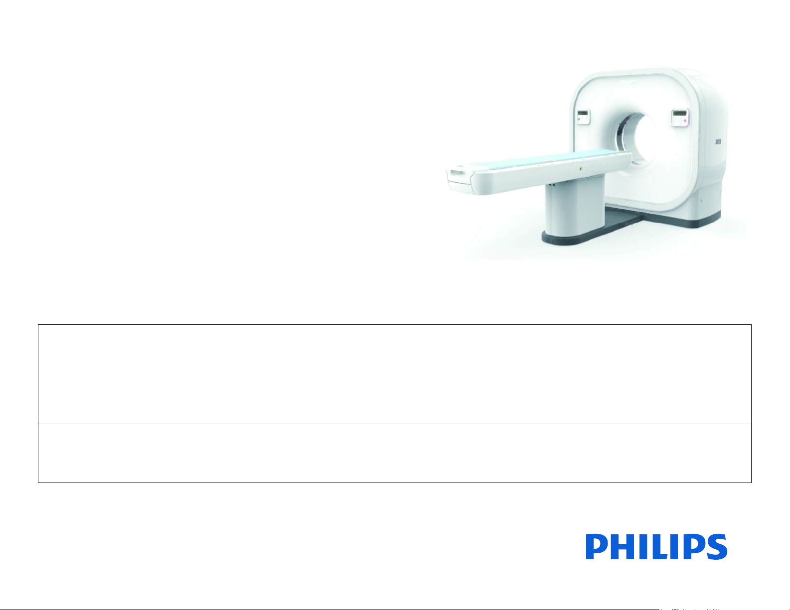
Access CT
SAS Installation Instructions
459800863451
Revision A
This document and the information contained in it is proprietary and confidential information of Philips Healthcare ("Philips") and may not be
reproduced, copied in whole or in part, adapted, modified, disclosed to others, or disseminated without the prior written permission of the Philips
Legal Department. Use of this document and the information contained in it is strictly reserved for current Philips personnel and Philips customers
who have a current and valid license from Philips for use by the customer’s designated in-house service employee on equipment located at the
customer’s designated site. Use of this document by unauthorized persons is strictly prohibited. Report violation of these requirements to the
Philips Legal Department. This document must be returned to Philips when the user is no longer licensed and in any event upon Philips’ first
written request.
This document and the information contained in it is strictly reserved for current Philips Healthcare (“Philips”) personnel, Philips licensed
representatives and Philips customers who have purchased a valid service agreement for use by the customer’s designated in-house service
employee on equipment located at the customer’s designated site. Use of this document by unauthorized persons is strictly prohibited. This
document must be returned to Philips when the user is no longer licensed and in any event upon Philips’ first written request.
© 2015 Koninklijke Philips N.V. All Rights Reserved. CSIP Level 1
Page 2

AccessCTSASInstallationInstructions
Safety and Legal Information
To the User of This Manual
Theuserofthismanualisdirectedtoreadandcarefullyreviewtheinstructions,warningsandcautionscontainedherein
priortobeginninginstallationorserviceactivities.Whileyoumayhavepreviouslyinstalledorservicedequipmentsimilar
tothatdescribedinthismanual,changesindesign,manufactureorproceduremayhaveoccurredwhichsignificantly
affectthepresentinstallationorservice.
Legal Manufacturer
PhilipsMedicalSystems(Cleveland),Inc.
APhilipsHealthcareCompany
595MinerRoad
Cleveland,OH44143
USA
Warranty Disclaimer
Philipsprovidesthisdocumentwithoutwarrantyofanykind,impliedorexpressed,including,butnotlimitedto,the
impliedwarrantiesofmerchantabilityandfitnessforaparticularpurpose.
Limitation of Liability
Philipshastakencaretoensuretheaccuracyofthisdocument.However,Philipsassumesnoliabilityforerrorsor
omissionsandreservestherighttomakechangeswithoutfurthernoticetoanyproductshereintoimprovereliability,
function,ordesign.Philipsmaymakeimprovementsorchangesintheproduct(s)orprogram(s)describedinthis
documentatanytime.
Password Notice
ThePASSWORDisthepropertyofPhilipsHealthcareandisprovidedfortheexclusivepurposeofprovidingaccessto
selectedserviceutilitieswhicharedescribedinthisservicemanualasbeingassociatedwiththepassword.Useofthis
passwordforanypurposeotherthanfortheaccesstotheselectedservicesutilitiesisstrictlyprohibited.
459800863451RevisionA CSIP Level 1WARNING: THIS PAGE CONTAINS COPYRIGHTED MATERIALS THAT ARE CONFIDE NTIAL AND OR PROPRIETARY. ANY RELEASE OR DISTRIBUTION OF THIS MATERIAL, WITHOUT PERMISSION, IS A VIOLATION OF LAW. 2
Page 3

AccessCTSASInstallationInstructions
Safety
WARNING: In addition to the warnings listed above, follow all safety guidelines as described in the
Safety Manual. Failure to do so can result in severe personal injury.
Installation and Environment
Exceptforinstallationsrequiringcertificationbythemanufacturer,seethataradiationprotectionsurveyismadebyaqualifiedexpert
inaccordancewithNCRP102,section7,asrevised.Performasurveyaftereverychangeinequipment,workload,oroperating
conditionswhichmightsignificantlyincreasetheprobabilityofpersonsreceivingmore
equivalent.
Diagnostic Imaging Systems - Mechanical-electrical Warning
WARNING: Before initiating a movement of the patient table or gantry, ensure that the area is free of
obstructions such as tools, boxes, chairs, and step stools. Physical injury or damage can
occur.
thanthemaximumpermissibledose
Allofthemoveableassembliesandpartsofthisequipmentshouldbeoperatedwithcareandroutinelyinspectedinaccordancewith
themanufacturer’srecommendationscontainedintheequipmentmanuals.
Onlyproperlytrainedandqualifiedpersonnelshouldbepermittedaccesstoanyinternalparts.Liveelectricalterminalsaredeadly;be
sureline
panels,orattachingaccessories.
Donotunderanycircumstancesremovetheflexiblehightensioncablesfromthex‐raytubehousingorhightensiongeneratorand/or
theaccesscoversfromthegeneratoruntilthemainand
abovemayresultinseriousorfatalbodilyinjuriestotheoperatororthoseinthearea.
disconnectsareopenedandotherappropriateprecautionsaretakenbeforeopeningaccessdoors,removingenclosure
auxiliarypowersupplieshavebeendisconnected.Failuretocomplywiththe
Priortoanyserviceandmaintenanceactivitiesinsidecomponents:
• Switchoffthesystematthemainpowersupply,andtheuninterruptiblepowersupply(UPS).
• Makesurethatnootherpersoncanswitchonpowerorswitchoffanysafetymeasures,wheninstallation,maintenanceorservice
workonthesystemisperformed.
• AlwaysuseanESDprotectionwriststrapwhenservicinganycomponentinthesystem.
459800863451RevisionA CSIP Level 1WARNING: THIS PAGE CONTAINS COPYRIGHTED MATERIALS THAT ARE CONFIDE NTIAL AND OR PROPRIETARY. ANY RELEASE OR DISTRIBUTION OF THIS MATERIAL, WITHOUT PERMISSION, IS A VIOLATION OF LAW. 3
Page 4

AccessCTSASInstallationInstructions
Electrical-grounding Instructions
Theequipmentmustbegroundedtoanearthgroundbyaseparateconductor.Theneutralsideofthelineisnottobeconsideredthe
earthground.Onequipmentprovidedwithalinecord,theequipmentmustbeconnectedtoaproperlygrounded,three‐pin
receptacle.Donotuseathree
‐to‐twopinadapter.
Diagnostic Imaging Systems - Radiation Warning
X‐rayandGamma‐raysaredangeroustobothoperatorandothersinthevicinityunlessestablishedsafeexposureproceduresare
strictlyobserved.
Theusefulandscatteredbeamscanproduceseriousorfatalbodilyinjuriestoanypersonsinthesurroundingareaifusedbyan
unskilledoperator.Adequateprecautionsmust
fromwithinthesourcehousingortoscatteredradiationresultingfromthepassageofradiationthroughmatter.
alwaysbetakentoavoidexposuretotheusefulbeam,aswellastoleakageradiation
Thoseauthorizedtooperate,participateinorsupervisetheoperationoftheequipmentmustbethoroughlyfamiliarand
comply
completelywiththecurrentestablishedsafeexposurefactorsandproceduresdescribedinpublications,suchas:SubchapterJofTitle
21oftheCodeofFederalRegulations,ʺDiagnosticX‐raySystemsandTheirMajorComponentsʺ,andthenationalcouncilonradiation
protection(NCRP)no.102,ʺMedicalX‐rayAndGamma
‐rayProtectionForEnergiesUpTo10Mev‐equipmentDesignandUseʺ.
Thoseresponsibleforplanningofx‐rayandgamma‐rayequipmentinstallationsmustbethoroughlyfamiliarandcomplycompletely
withNCRPno.49,ʺStructuralShieldingDesignandEvaluationforMedicalofX‐raysandGamma‐raysofEnergies
Upto10Mevʺ.
Failuretoobservethesewarningsmaycauseseriousorfatalbodilyinjuriestotheoperatororthoseinthearea.
459800863451RevisionA CSIP Level 1WARNING: THIS PAGE CONTAINS COPYRIGHTED MATERIALS THAT ARE CONFIDE NTIAL AND OR PROPRIETARY. ANY RELEASE OR DISTRIBUTION OF THIS MATERIAL, WITHOUT PERMISSION, IS A VIOLATION OF LAW. 4
Page 5
AccessCTSASInstallationInstructions
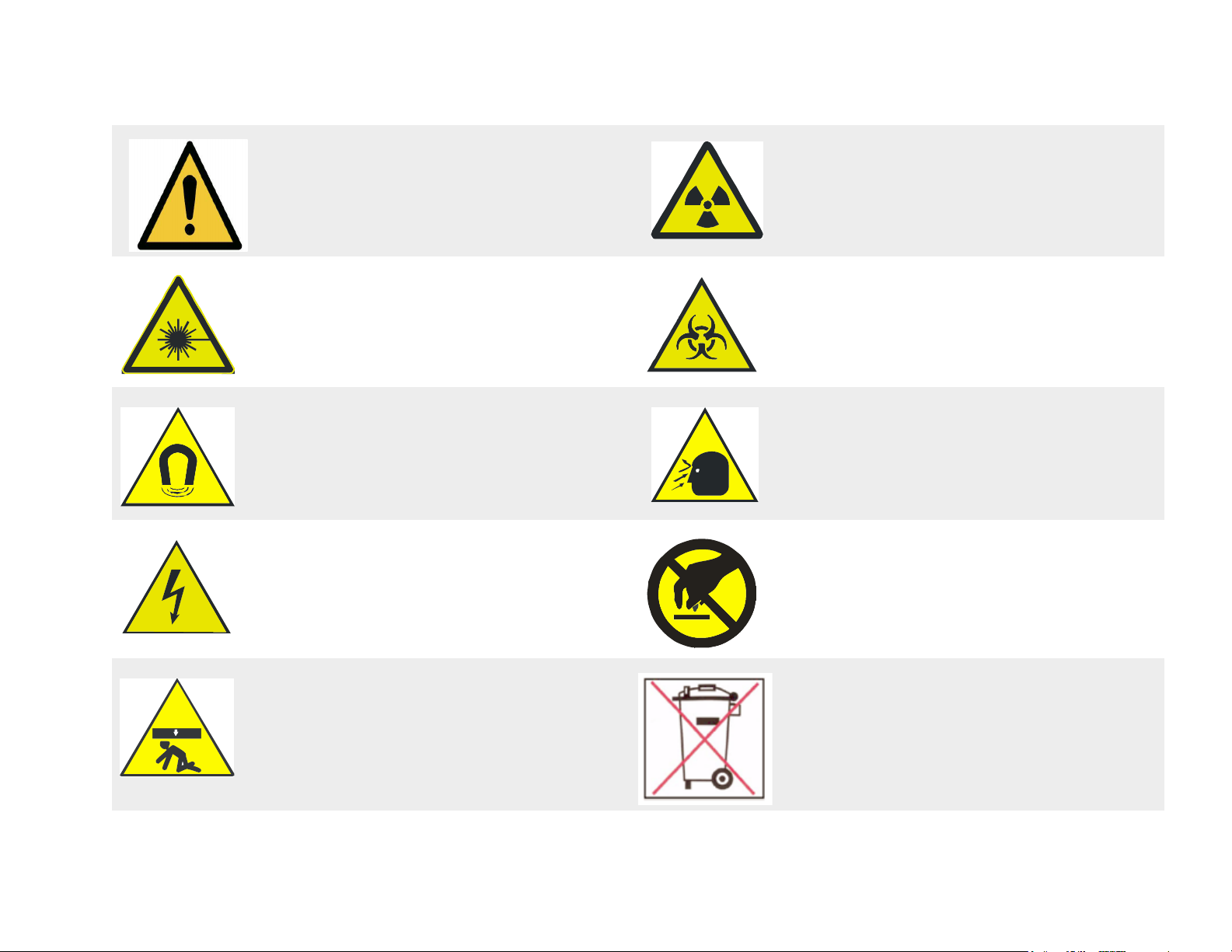
Symbol Descriptions
War ningsymbol Radiationwarningsymbol
Laserwarningsymbol Biohazardwarningsymbol
Magnetismwarningsymbol Projectilewarningsymbol
Electricalwarningsymbol Donottouch
Recycle Label
Disposeofinaccordancewithyourcountry’s
requirements.Thislabelindicatesthatthereis
Crushwarningsymbol
459800863451RevisionA CSIP Level 1WARNING: THIS PAGE CONTAINS COPYRIGHTED MATERIALS THAT ARE CONFIDE NTIAL AND OR PROPRIETARY. ANY RELEASE OR DISTRIBUTION OF THIS MATERIAL, WITHOUT PERMISSION, IS A VIOLATION OF LAW. 5
materialinthesystemthatyoumustseparately
collectandrecycleinaccordancewiththe
requirementsoftheEuropeanWa steElectrical
Equipment(WEEE)Directive.
Page 6

AccessCTSASInstallationInstructions
ECO# Revision Date Comments
E‐057698 A May2015 NewRelease
ThisdocumentwaspreparedbyCT/AMIServiceInnovations.
Foranyadditions,corrections,orsuggestions,contactyournextlevelofsupport.
Revision History
459800863451RevisionA CSIP Level 1 WARNING: THIS PAGE CONTAINS COPYRIGHTED MATERIALS THAT ARE CONFIDENTIAL AND OR PROPRIETARY. ANY RELEASE OR DISTRIBUTION OF THIS MATERIAL, WITHOUT PERMISSION, IS A VIOLATION OF LAW. 6
Page 7

SAS (Spiral Auto Start) Option........................................................................................................ 8
Overview.................................................................................................................................................................8
SAS Option Block Diagram...............................................................................................................................8
Tools .................................................................................................................................................................9
Time ..................................................................................................................................................................9
Supported Injectors ..............................................................................................................................................10
Injector -- Scanner Setup......................................................................................................................................14
Safety..............................................................................................................................................................14
MEDRAD Envision CT Injector .......................................................................................................................15
MEDTRON Injektron 82 CT Injector................................................................................................................16
NEMOTO Auto Enhance A-60 Injector ...........................................................................................................18
SHENZEN DONGA NSJ-200C Injector ..........................................................................................................20
MEDRAD VISTRON CT Injector .....................................................................................................................21
TYCO CT9000 ADV Injector ...........................................................................................................................25
Optivantage Injector........................................................................................................................................29
Ulrich OHIO tandem XD 2002.........................................................................................................................30
Appendix A: Interface Cable Pin Layouts ......................................................................................32
Overview...............................................................................................................................................................32
Nemoto Auto Enhanced CT Injector Cable ..........................................................................................................32
Medrad Envision CT Injector and Medrad Stellant D (SX) Injector Cable ............................................................33
Medrad Vistron Injector Interface Cable...............................................................................................................34
Tyco CT9000 ADV Digital Injector Interface Cable ..............................................................................................35
Optivantage Injector Interface Cable ....................................................................................................................36
Ulrich Injector Interface Cable ..............................................................................................................................37
459800863451RevisionA CSIP Level 1 WARNING: THIS PAGE CONTAINS COPYRIGHTED MATERIALS THAT ARE CONFIDENTIAL AND OR PROPRIETARY. ANY RELEASE OR DISTRIBUTION OF THIS MATERIAL, WITHOUT PERMISSION, IS A VIOLATION OF LAW. 7
Page 8
AccessCTSASInstallationInstructions SAS(SpiralAutoStart)Option
Section 1 SAS (Spiral Auto Start) Option
1.1 Overview
TheSAS(SpiralAutoStart)optionisusedincaseswhentimingbetweenspiralscanandcontrastinjection
isimportant.Insuchcases,theSASoptionenablestheautomaticstartofthespiralscanatthebeginning
oftheinjection.
ThepurposeofthisdocumentistoguidetheFieldServiceEngineerthroughtheSASinstallation
procedures.
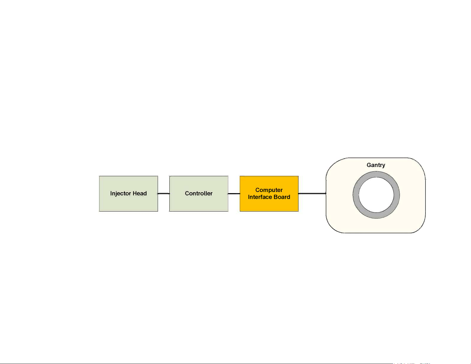
1.1.1 SAS Option Block Diagram
Figure 1:
459800863451RevisionA CSIP Level 1WARNING: THIS PAGE CONTAINS COPYR IGHTED MATERIALS THAT ARE CONFIDENTIAL AND OR PROPRIETARY. ANY RELEASE OR DISTRIBUTION O F THIS MATERIAL, WITHOUT PERMISSION, IS A VIOLATION OF LAW. 8
Page 9
AccessCTSASInstallationInstructions SAS(SpiralAutoStart)Option
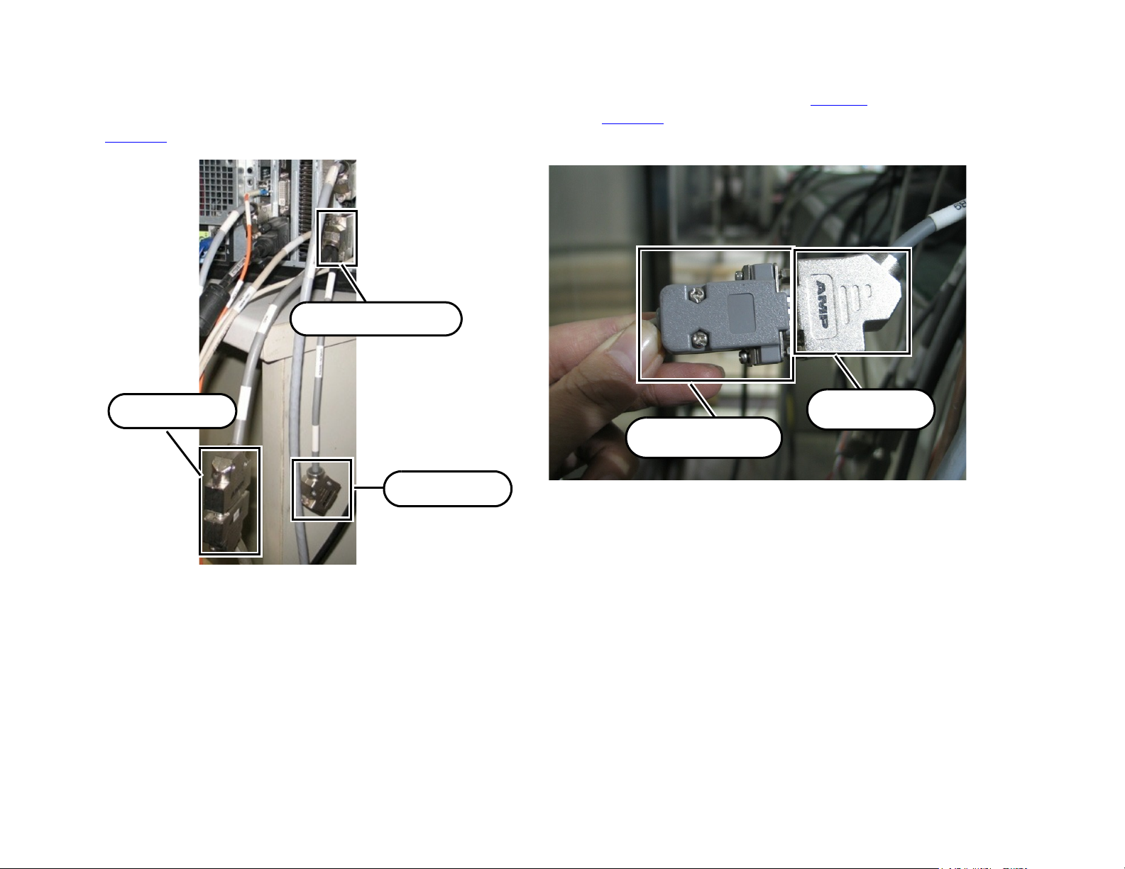
X1-0475 Connector
X2 Connector
X1 Connector
X2 Connector
Injector Connector
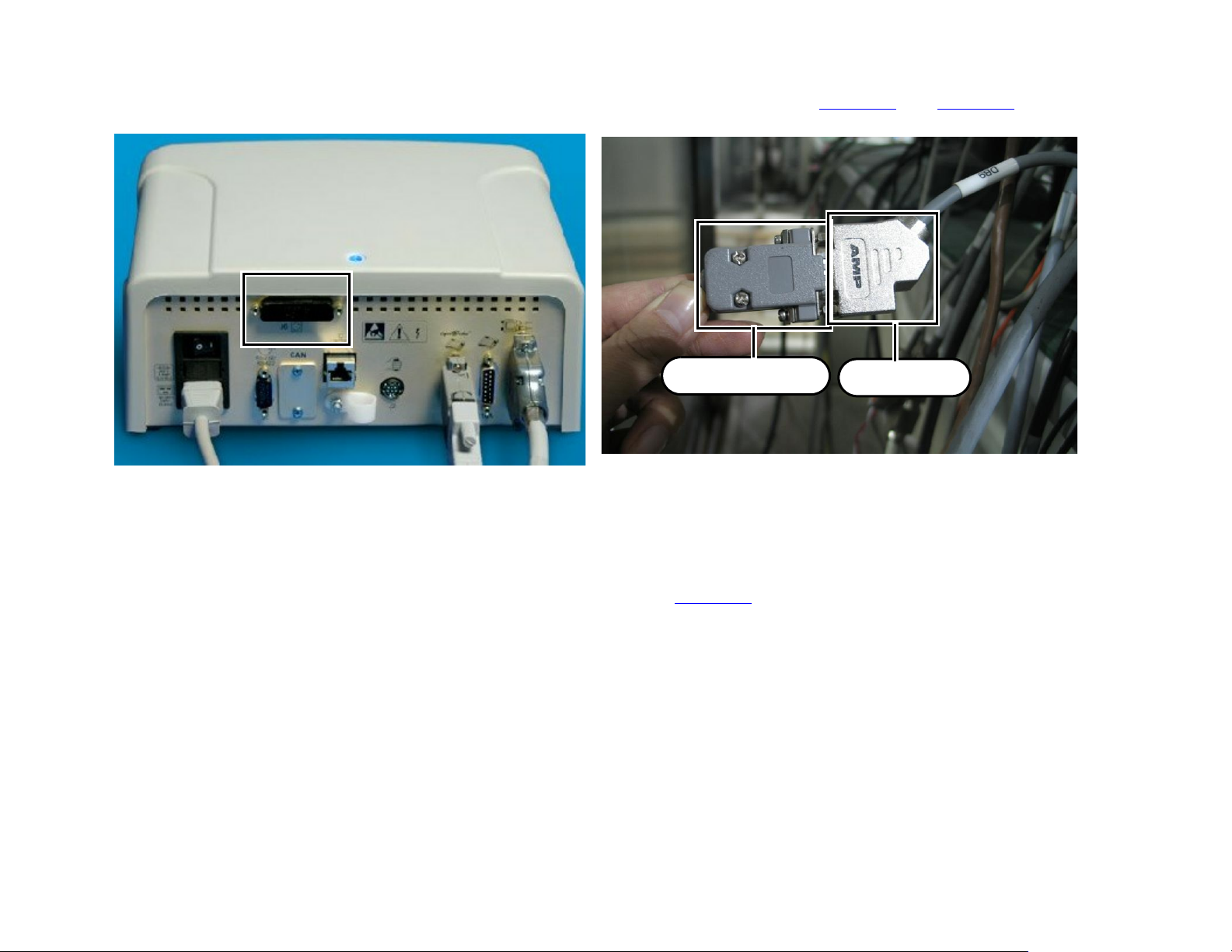
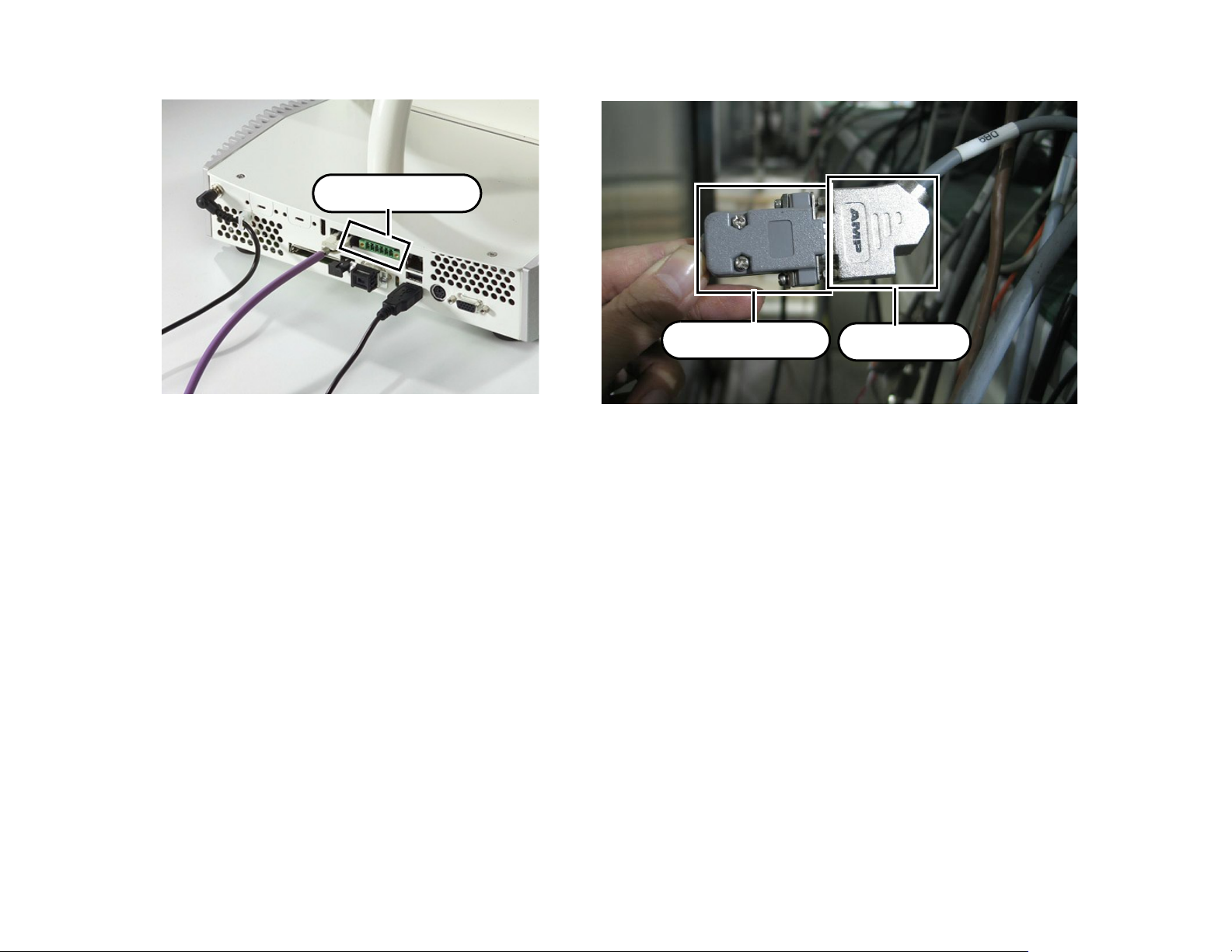
TheSASoptionprovidesfordirectcableconnectionbetweenthesupportedinjectorslistedinTable 1onpage 10
andtheDB9terminal—X2connectorfromX1‐0475connector(seeFigure 2)ontheConsoleInterfaceBoard(see
Figure 3).
1.1.2 Tools
1.1.3 Time
459800863451RevisionA CSIP Level 1WARNING: THIS PAGE CONTAINS COPYR IGHTED MATERIALS THAT ARE CONFIDENTIAL AND OR PROPRIETARY. ANY RELEASE OR DISTRIBUTION O F THIS MATERIAL, WITHOUT PERMISSION, IS A VIOLATION OF LAW. 9
Figure 2:
StandardFSEtoolskit
Estimatedtime1.5hours
Figure 3:
X2Connector
Page 10
AccessCTSASInstallationInstructions SAS(SpiralAutoStart)Option
1.2 Supported Injectors
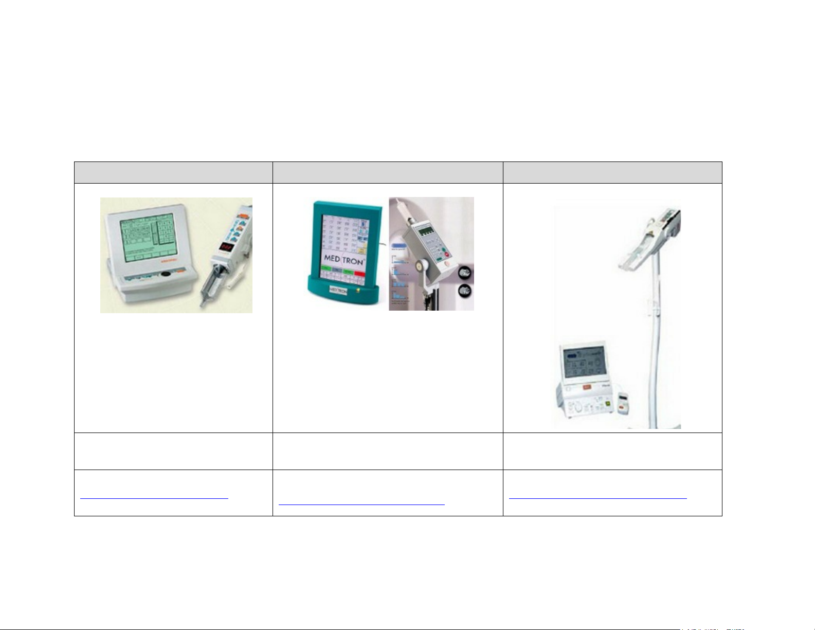
AtpresenttheAccessCTsupportsthefollowingsixdifferentinjectormodels.Interfacecablesare
suppliedbyPhilipsunlessotherwisespecified.
Table 1: SupportedInjectors
MEDRAD Envision CT MEDTRON Injektron 82 CT NEMOTO Auto Enhance A-60
PhilipsInterfaceCable
P/N454110191571
Forsetup,see
MEDRAD Envision CTInjector
15
459800863451RevisionA CSIP Level 1WARNING: THIS PAGE CONTAINS COPYR IGHTED MATERIALS THAT ARE CONFIDENTIAL AND OR PROPRIETARY. ANY RELEASE OR DISTRIBUTION O F THIS MATERIAL, WITHOUT PERMISSION, IS A VIOLATION OF LAW. 10
on page
MedtronInterfaceCable
P/NFIF82CT.1GB
Forsetup,see
MEDTRONInjektron82CTInjector
onpage16
PhilipsInterfaceCable
P/N454110191561
Forsetup,see
NEMOTOAutoEnhanceA‐60Injector
page18
on
Page 11
AccessCTSASInstallationInstructions SAS(SpiralAutoStart)Option
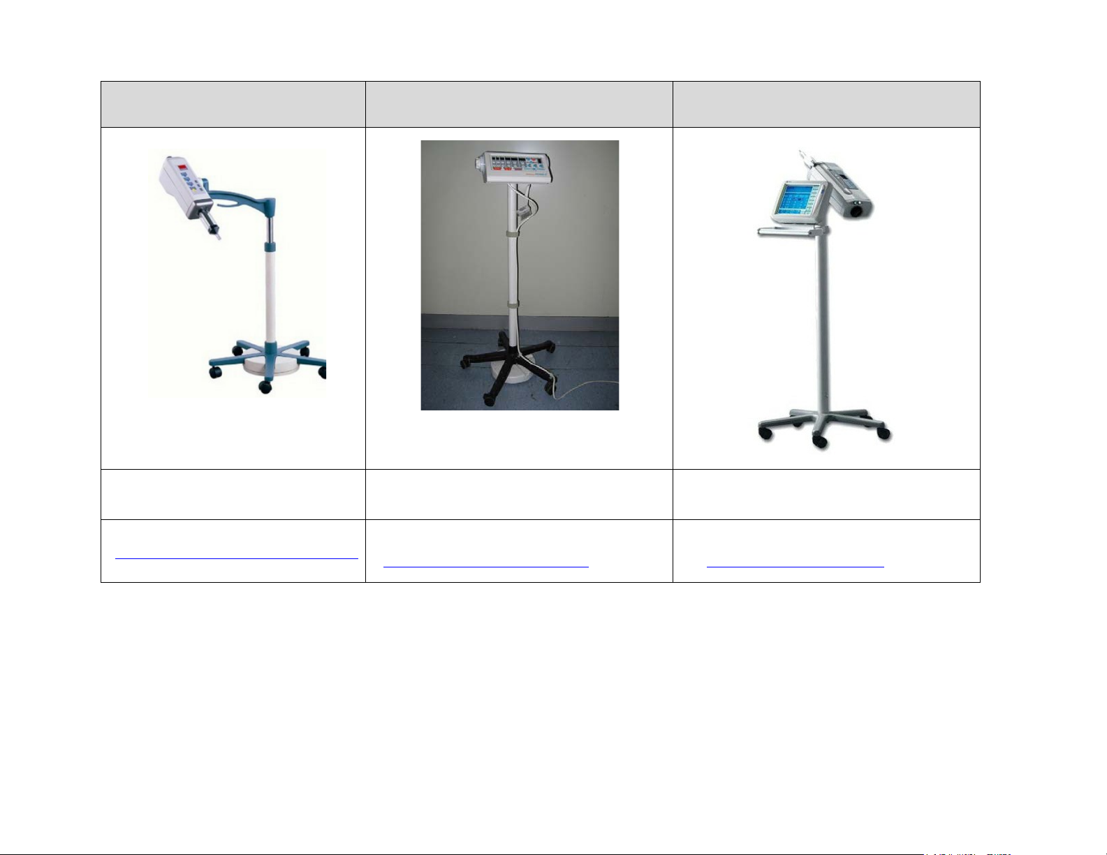
SHENZHEN DONGA NSJ 200C
Injector
ShenzhenDongdaInterfaceCable
P/NW2300
MEDRAD VISTRON CT Injector TYCO CT9000 ADV Injector
MEDRADVISTRONCTInjector
P/N454110191671
TYCOCT9000ADVInjector
P/N454110191681
Forsetup,see
SHENZENDONGANSJ‐200CInjector
onpage20
459800863451RevisionA CSIP Level 1WARNING: THIS PAGE CONTAINS COPYR IGHTED MATERIALS THAT ARE CONFIDENTIAL AND OR PROPRIETARY. ANY RELEASE OR DISTRIBUTION O F THIS MATERIAL, WITHOUT PERMISSION, IS A VIOLATION OF LAW. 11
MEDRADVISTRONCTInjector
Forsetup,see
onpage21
Forsetup,see
TYCOCT9000ADVInjector onpage25
Page 12
AccessCTSASInstallationInstructions SAS(SpiralAutoStart)Option
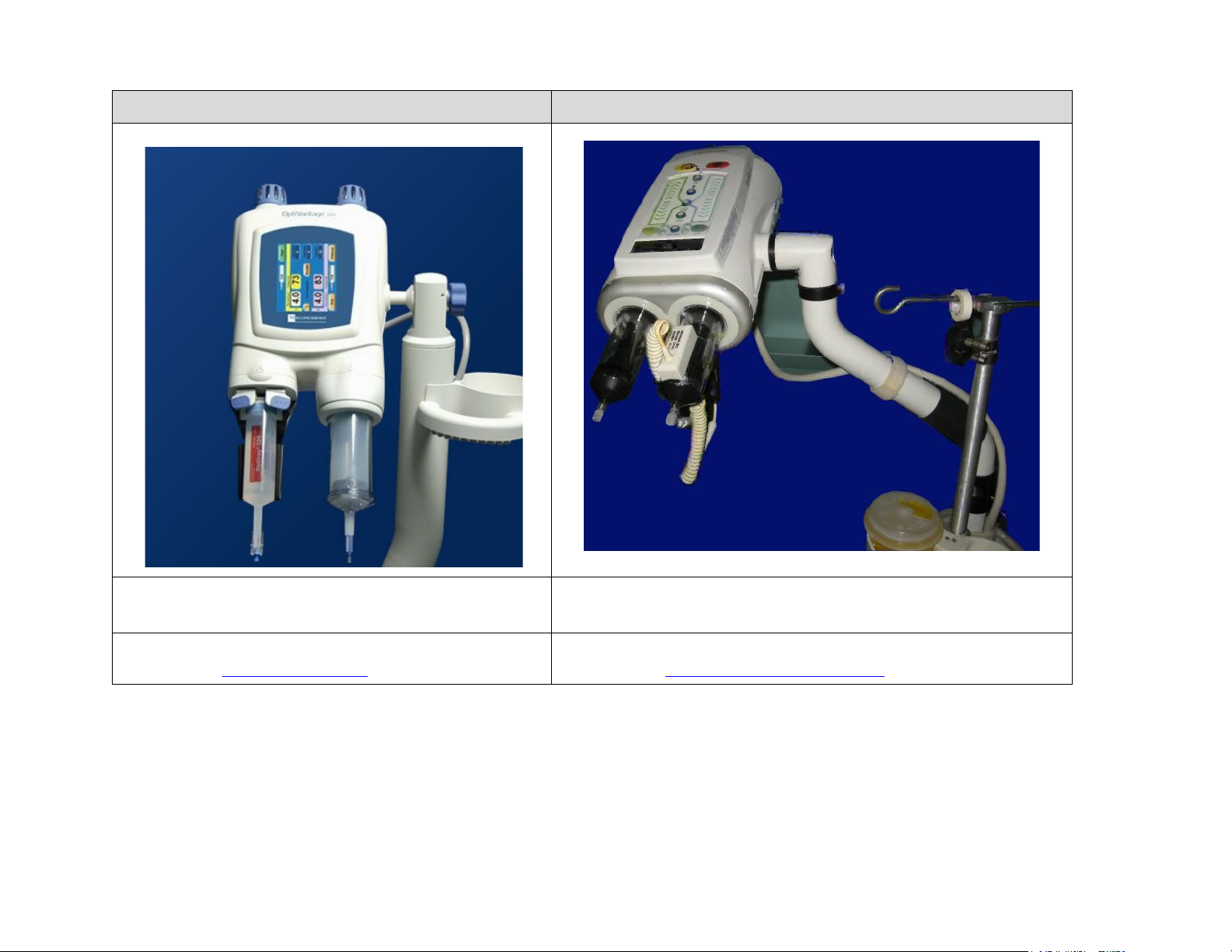
Optivantage Injector Medrad Stellant D (SX) Injector
OptivantageCTInjector
P/N454110124241
Forsetup,see
OptivantageInjector
459800863451RevisionA CSIP Level 1WARNING: THIS PAGE CONTAINS COPYR IGHTED MATERIALS THAT ARE CONFIDENTIAL AND OR PROPRIETARY. ANY RELEASE OR DISTRIBUTION O F THIS MATERIAL, WITHOUT PERMISSION, IS A VIOLATION OF LAW. 12
onpage29
MedradStellantD(SX)InjectorCable
P/N454110191571
Forsetup,see
MEDRADEnvisionCTInjector onpage15
Page 13
AccessCTSASInstallationInstructions SAS(SpiralAutoStart)Option
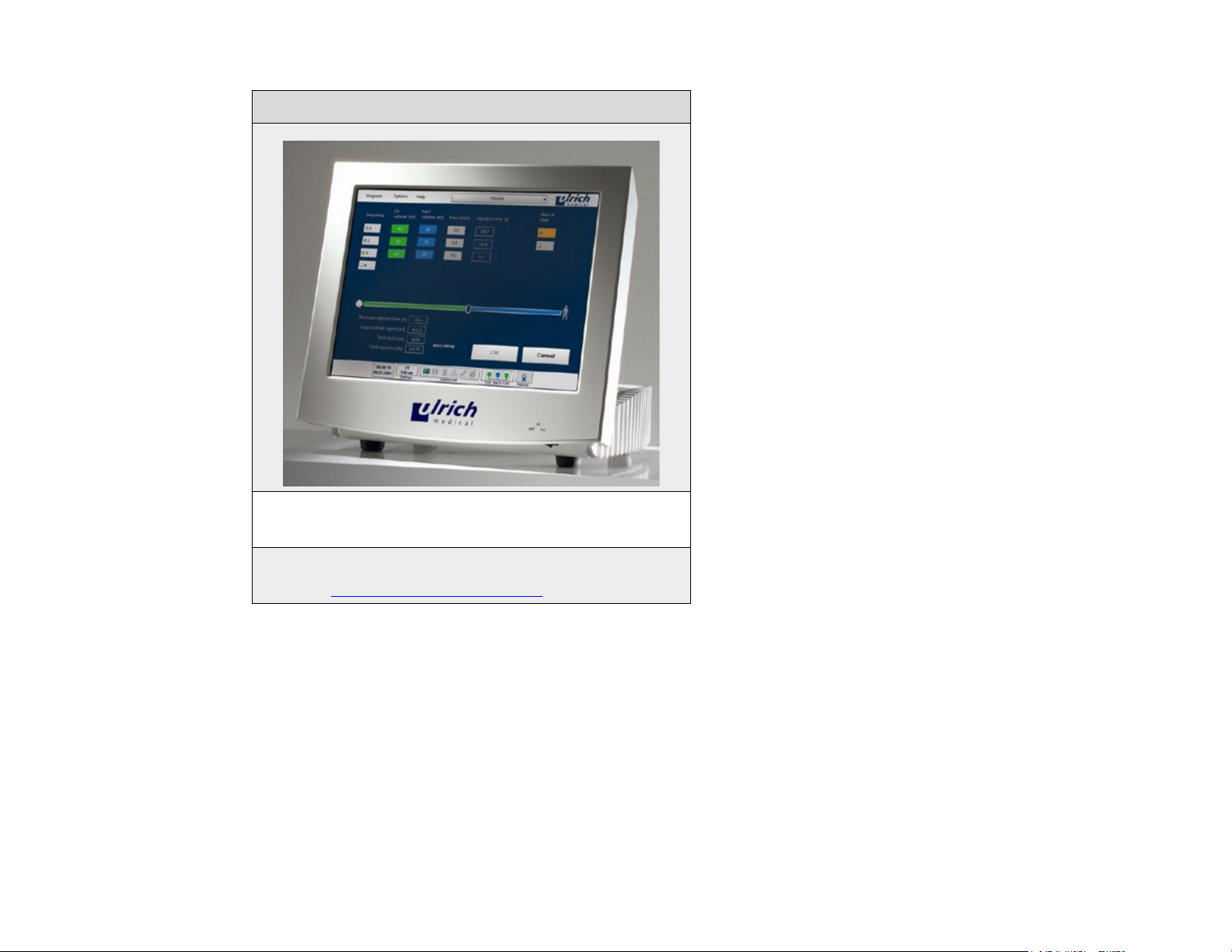
Ulrich OHIO tandem XD 2002
UlrichOHIOtandemXD2002InjectorCable
P/N454110415861
Forsetup,see
UlrichOHIOtandemXD2002
459800863451RevisionA CSIP Level 1WARNING: THIS PAGE CONTAINS COPYR IGHTED MATERIALS THAT ARE CONFIDENTIAL AND OR PROPRIETARY. ANY RELEASE OR DISTRIBUTION O F THIS MATERIAL, WITHOUT PERMISSION, IS A VIOLATION OF LAW. 13
onpage30
Page 14

AccessCTSASInstallationInstructions SAS(SpiralAutoStart)Option
!
!
!
1.3 Injector -- Scanner Setup
1.3.1 Safety
WARNING: Obstruction Hazard! Route all cables through existing troughs, ducts, or adjacent to system
components to prevent obstructions that can cause personnel to trip or fall, or damage to
the cables.
WARNING: Point of injury! System Components can have sharp edges that may cause injury to
personnel.
WARNING: Follow all safety guidelines as described in the safety Guidelines Manual. Failure to do so
can result in severe personal injury.
459800863451RevisionA CSIP Level 1WARNING: THIS PAGE CONTAINS COPYR IGHTED MATERIALS THAT ARE CONFIDENTIAL AND OR PROPRIETARY. ANY RELEASE OR DISTRIBUTION O F THIS MATERIAL, WITHOUT PERMISSION, IS A VIOLATION OF LAW. 14
Page 15
AccessCTSASInstallationInstructions SAS(SpiralAutoStart)Option
P/N454110191571
1.3.2 MEDRAD Envision CT Injector
Cable 4541 10191571
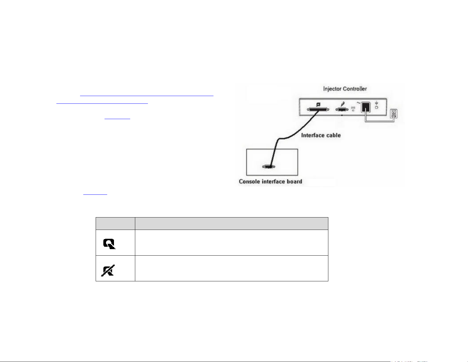
SetuptheMedradInjectorconnectiontotheAccessCTasfollows:
1. ConnecttheInterfacecable(forcablepinlayoutsee
sectionMedradEnvisionCTInjectorandMedrad
StellantD(SX)InjectorCable onpage33)betweenthe
CTBoxConsoleInterfaceBoardandtheInjector
Controller(seeFigure 4).
2. ChecktheconfigurationoftheEnvisionCTinjector
fortheCommunicatorasfollows:
a. FromtheHelpscreen,selectConfigureSystem.
b. SelectPageDown.
3. Topermitcommunicationbetweentheinjectorand
theCTscanner,selectONfortheCommunicator.
WhentheCommunicatorisON,oneofthesymbols
listedinTable 2onpage 15symbolappearsonthe
Protocol,Arming,andInjectingscreens.
Figure 4:
Table 2: CommunicatorSymbols
Symbol Description
Displayediftheinterfaceisoperational.
Displayediftheinterfaceisnotoperational.
WhentheCommunicatorisON:
• The injector will trigger the CT scanner to start the scan.
• The Communicator will send a constant signal to the scanner if the Scan Delay Setting is 00:000.
459800863451RevisionA CSIP Level 1WARNING: THIS PAGE CONTAINS COPYR IGHTED MATERIALS THAT ARE CONFIDENTIAL AND OR PROPRIETARY. ANY RELEASE OR DISTRIBUTION O F THIS MATERIAL, WITHOUT PERMISSION, IS A VIOLATION OF LAW. 15
Page 16
AccessCTSASInstallationInstructions SAS(SpiralAutoStart)Option
InterfaceCable
Connector
Injector
Connector
•
The Communicator will accept a signal from the scanner to initiate the injection once the injector is
armed.
Note: WhenSASisnotinuse:
• Make sure to turn the Communicator OFF after all phases of the injector are complete.
• To trigger the CT scanner again set the Communicator to ON.
1.3.3 MEDTRON Injektron 82 CT Injector
Setup
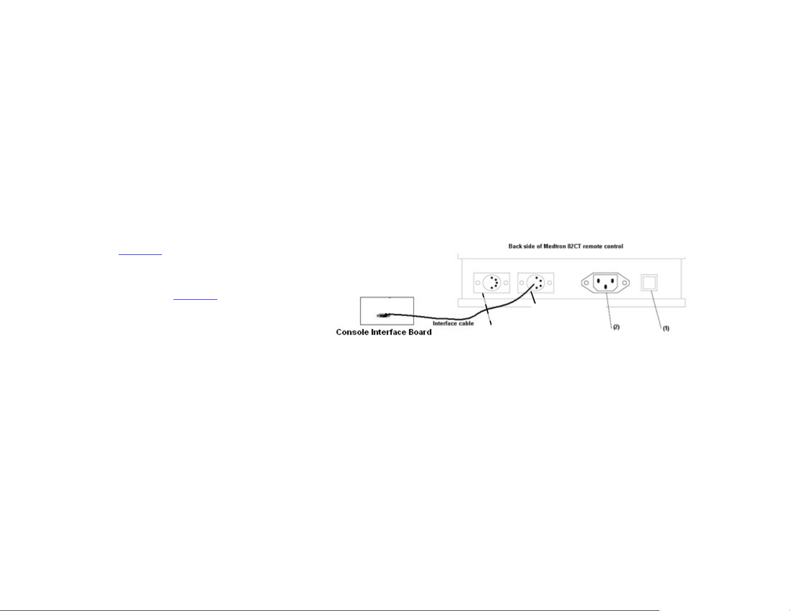
SetuptheMedtronInjectorconnectiontotheAccessCTasfollows:
1. InserttheinterfacecableintosocketNo.3
(seeFigure 5).
2. Connecttheotherendoftheinterface
cableintotheX2connectorfromX1‐0475
connector(seeFigure 2)ontheConsole
InterfaceBoard.
Note: TheInterfacecableissuppliedby
Medtron.
Figure 5:
Operation
TheX‐ray‐start‐functionsynchronizestheinjectorandthescanner:Toenablethesynchronization,arelay
isswitchedONfromtheconsoleortheremoteconsoleinterface.
Note: ForSafetyreasonstheinterface‐functionmustbeswitchedonbeforeeverynewexamination.
1. PressX‐Ray‐Start(6)
2. Setastarttime.
459800863451RevisionA CSIP Level 1WARNING: THIS PAGE CONTAINS COPYR IGHTED MATERIALS THAT ARE CONFIDENTIAL AND OR PROPRIETARY. ANY RELEASE OR DISTRIBUTION O F THIS MATERIAL, WITHOUT PERMISSION, IS A VIOLATION OF LAW. 16
Page 17

AccessCTSASInstallationInstructions SAS(SpiralAutoStart)Option
•
X-ray start time > 0; Injection function ON
• X-ray start time = 0; Injection function OFF
3. Starttheinjection.
Note: TheinterfaceStartfunctionisautomaticallydisabledwhentheinjectionstops.
459800863451RevisionA CSIP Level 1WARNING: THIS PAGE CONTAINS COPYR IGHTED MATERIALS THAT ARE CONFIDENTIAL AND OR PROPRIETARY. ANY RELEASE OR DISTRIBUTION O F THIS MATERIAL, WITHOUT PERMISSION, IS A VIOLATION OF LAW. 17
Page 18
AccessCTSASInstallationInstructions SAS(SpiralAutoStart)Option
PN454110191561
1.3.4 NEMOTO Auto Enhance A-60 Injector
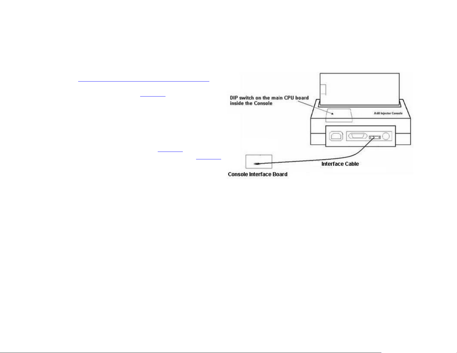
SetuptheNemotoInjectorconnectiontotheAccessCTasfollows:
1. Connecttheinterfacecable(forcablepinlayoutsee
sectionNemotoAutoEnhancedCTInjectorCable on
page32)betweentheCTBoxConsoleInterfaceBoard
andInjectorController(seeFigure 6).
2. SettheDIPSwitchonthemainCPUboardinsidethe
A‐60injectorconsoleasfollows:
a. OpenthecoveronthebackoftheA‐60injector
console.
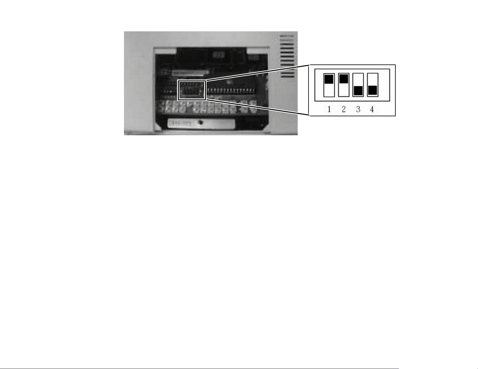
b. LocatetheDIPswitchonthemainCPUboard
insidetheconsoleasshowninFigure 7onpage 19.
ChangetheDIPSwitchsettingasshowninFigure 7
onpage 19.
Afterthesesettingsarecomplete,theInjectorwilltrigger
theCTtoscanwheninitialized.
However,iftheStartswitchispressedaftertemporary
suspension,the“CT‐START“signalwillnotbesent.
Figure 6:
459800863451RevisionA CSIP Level 1WARNING: THIS PAGE CONTAINS COPYR IGHTED MATERIALS THAT ARE CONFIDENTIAL AND OR PROPRIETARY. ANY RELEASE OR DISTRIBUTION O F THIS MATERIAL, WITHOUT PERMISSION, IS A VIOLATION OF LAW. 18
Page 19
AccessCTSASInstallationInstructions SAS(SpiralAutoStart)Option
Figure 7: SettingdetailfortheA‐60Injectorconsole
459800863451RevisionA CSIP Level 1WARNING: THIS PAGE CONTAINS COPYR IGHTED MATERIALS THAT ARE CONFIDENTIAL AND OR PROPRIETARY. ANY RELEASE OR DISTRIBUTION O F THIS MATERIAL, WITHOUT PERMISSION, IS A VIOLATION OF LAW. 19
Page 20
AccessCTSASInstallationInstructions SAS(SpiralAutoStart)Option
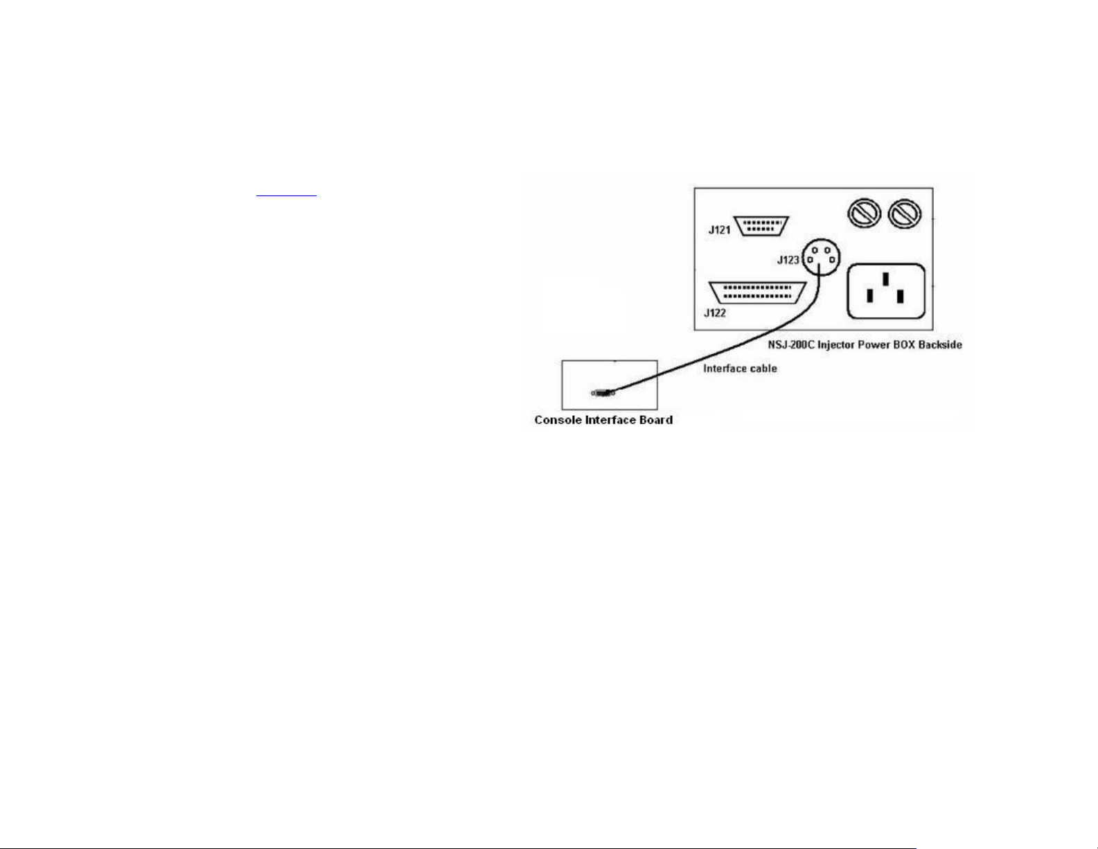
1.3.5 SHENZEN DONGA NSJ-200C Injector
SetuptheShenzhenDongaInjectorconnectiontotheAccessCTasfollows:
1. ConnecttheinterfacecablebetweentheCTscanner
andinjector(seeFigure 6).
2. SetthemodeofNSJ‐200Casfollows:
a. OntheLCDscreendisplay,selectMODE.
b. PressthemenuuntiltheONLINEstring
appearsonthetoprightcorneroftheLCD
screen.
c. PressSTOREtousethismode.
Figure 8:
Note: Intheonlinemode,theNSJ‐200Cinjectorwillfirstdetectthestatusoftheshort‐circuitingsignalsintheinterface
cable.Ifcorrect,theinjectorwilltriggertheCTtoscan,whenitbeginstowork.WhennotusingtheInjector,setitto
Offlinemode.
459800863451RevisionA CSIP Level 1WARNING: THIS PAGE CONTAINS COPYR IGHTED MATERIALS THAT ARE CONFIDENTIAL AND OR PROPRIETARY. ANY RELEASE OR DISTRIBUTION O F THIS MATERIAL, WITHOUT PERMISSION, IS A VIOLATION OF LAW. 20
Page 21
AccessCTSASInstallationInstructions SAS(SpiralAutoStart)Option
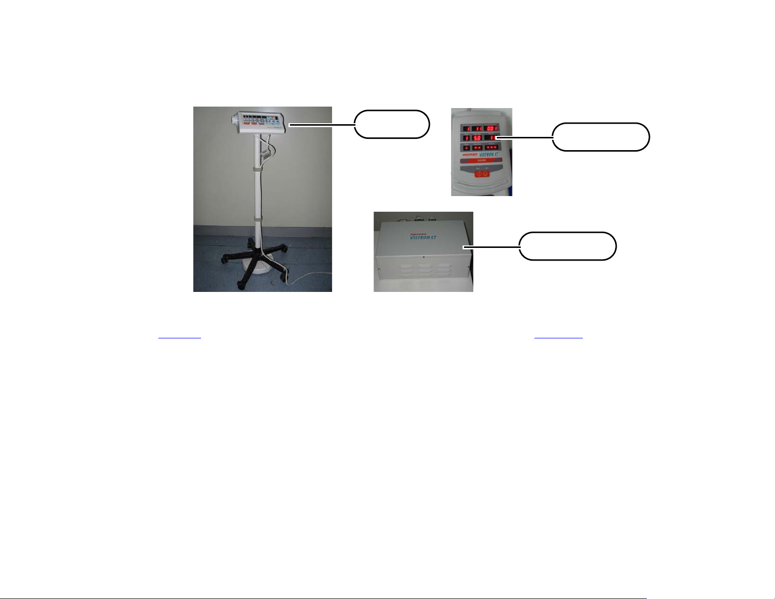
Injector
Remote Panel
Remote Control
1.3.6 MEDRAD VISTRON CT Injector
SetuptheMEDRADVISTRONInjectorconnectiontotheAccessCTasfollows:
Figure 9: InjectorParts
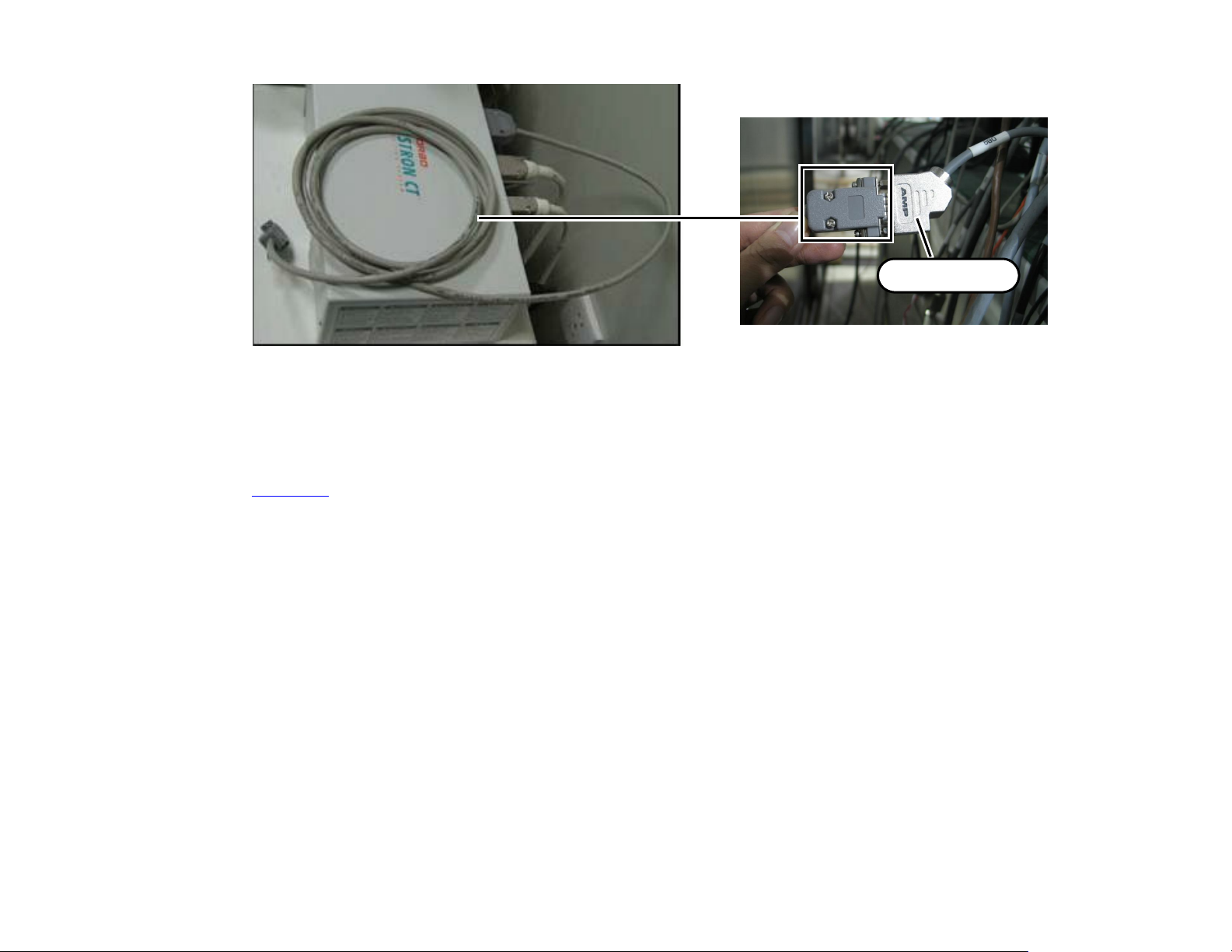
ConnecttheInterfacecable(P/N454110191671)betweentheX2connectorfromX1‐0475connector(see
Figure 2)ontheConsoleInterfaceBoardandtheInjectorController(seeFigure 10).
459800863451RevisionA CSIP Level 1WARNING: THIS PAGE CONTAINS COPYR IGHTED MATERIALS THAT ARE CONFIDENTIAL AND OR PROPRIETARY. ANY RELEASE OR DISTRIBUTION O F THIS MATERIAL, WITHOUT PERMISSION, IS A VIOLATION OF LAW. 21
Page 22
AccessCTSASInstallationInstructions SAS(SpiralAutoStart)Option
X2 Connector
Figure 10: CableConnection
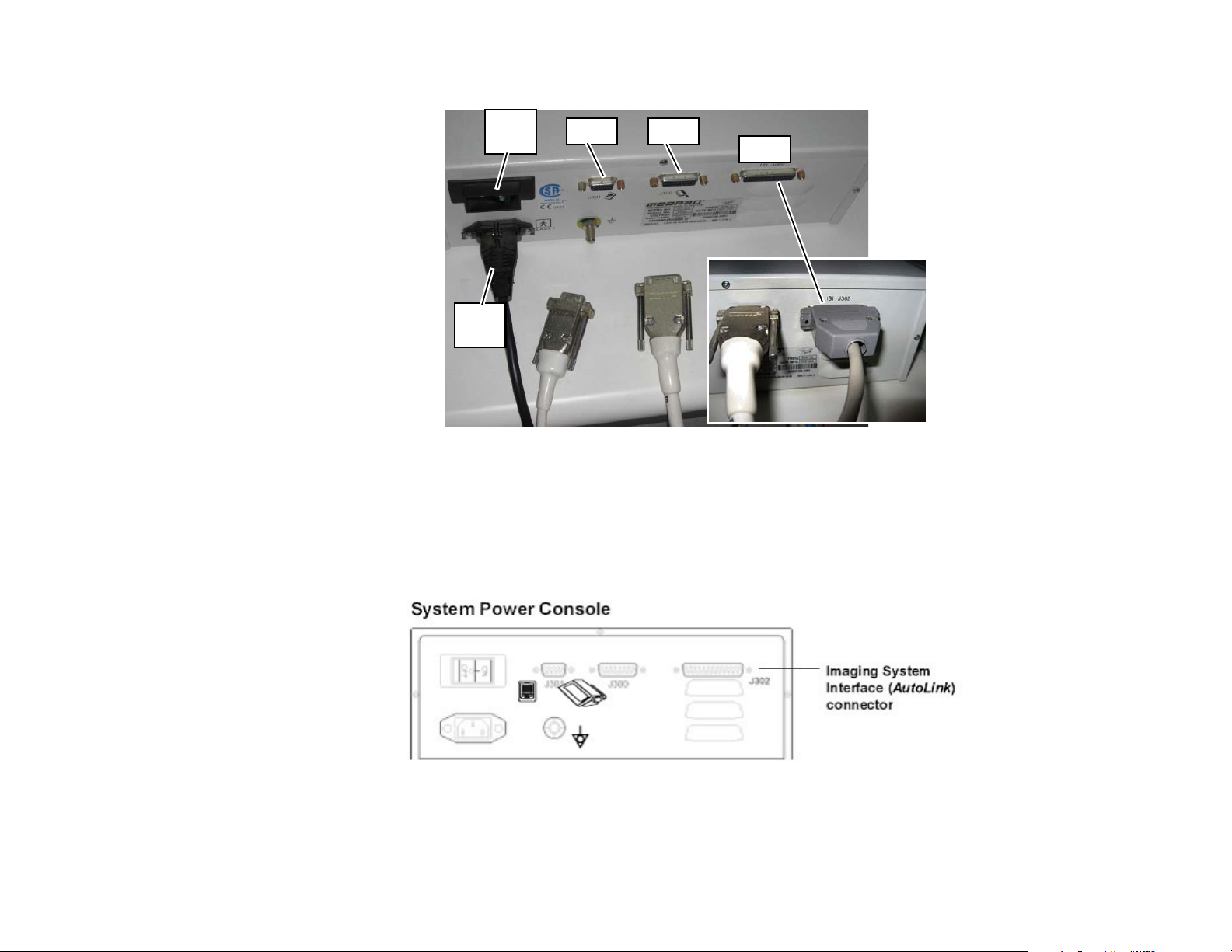
TheMEDRADVISTRONInjectorRemoteControlunitincludesthefollowinginterfaceconnectors(see
Figure 11):
• J300 (Female DB9): Connects between the Injector and the Remote Control unit.
• J301 (Female DB15): Connects between the Remote Panel and the Remote Control unit.
459800863451RevisionA CSIP Level 1WARNING: THIS PAGE CONTAINS COPYR IGHTED MATERIALS THAT ARE CONFIDENTIAL AND OR PROPRIETARY. ANY RELEASE OR DISTRIBUTION O F THIS MATERIAL, WITHOUT PERMISSION, IS A VIOLATION OF LAW. 22
Page 23
AccessCTSASInstallationInstructions SAS(SpiralAutoStart)Option
J300J301
J302
Power
Switch
Power
supply
•
J302 (FemalDB25): Imaging System Interface (ISI) connector.
Figure 11: CableandConnectorDetail
AutoLink Installation
TheAutoLinkoptionenablestheinjectortointerfacewithaCTscanner.Theinterfacepermitsthescanner
tobestartedbytheinjector.
Figure 12:
459800863451RevisionA CSIP Level 1WARNING: THIS PAGE CONTAINS COPYR IGHTED MATERIALS THAT ARE CONFIDENTIAL AND OR PROPRIETARY. ANY RELEASE OR DISTRIBUTION O F THIS MATERIAL, WITHOUT PERMISSION, IS A VIOLATION OF LAW. 23
Page 24

AccessCTSASInstallationInstructions SAS(SpiralAutoStart)Option
AutoLink Operation
Is the AutoLink available on your system
TheJ302connector,locatedontherearpanelofthesystempowerconsoleisrequiredfortheAutoLink
interface.TheAutolinkinterfacecableisalsorequiredtoconnecttheinjectorwiththescanner.
IftheAutolinkisinstalledandoperational,theP151messagecodewillbedisplayedtheveryfirsttimethe
injectorisswitchedONafterAutolinkisinstalled.PresstheinjectmodekeytoconfirmtheAutolinkis
nowenabled.TheP151codemessagecodewillclose.
Scan Delay and the Scanner
Ifascandelayisrequired,itmustbeprogrammedpriortoarmingtheinjector.Thescandelayrange:0to
99seconds.
The Scan Delay Timer on the Injector
TheScanDelayTimercountsdownandpromptstheoperatorwhenthescanstarts.
Aftertheinjectionstarts,thescandelaystartstocountdown.Theinjectorbeepseverysecondduringthe
last10secondsofthecount.Whenthetimerdisplayszero,theinjectorbeepsfivetimestosignalthatthe
delayhasended.
459800863451RevisionA CSIP Level 1WARNING: THIS PAGE CONTAINS COPYR IGHTED MATERIALS THAT ARE CONFIDENTIAL AND OR PROPRIETARY. ANY RELEASE OR DISTRIBUTION O F THIS MATERIAL, WITHOUT PERMISSION, IS A VIOLATION OF LAW. 24
Page 25
AccessCTSASInstallationInstructions SAS(SpiralAutoStart)Option
Universal
Connector
Panel
Connectors
(1&2)
Injector
Connector
Power
Switch
Power
Connector
Remote PanelInjector
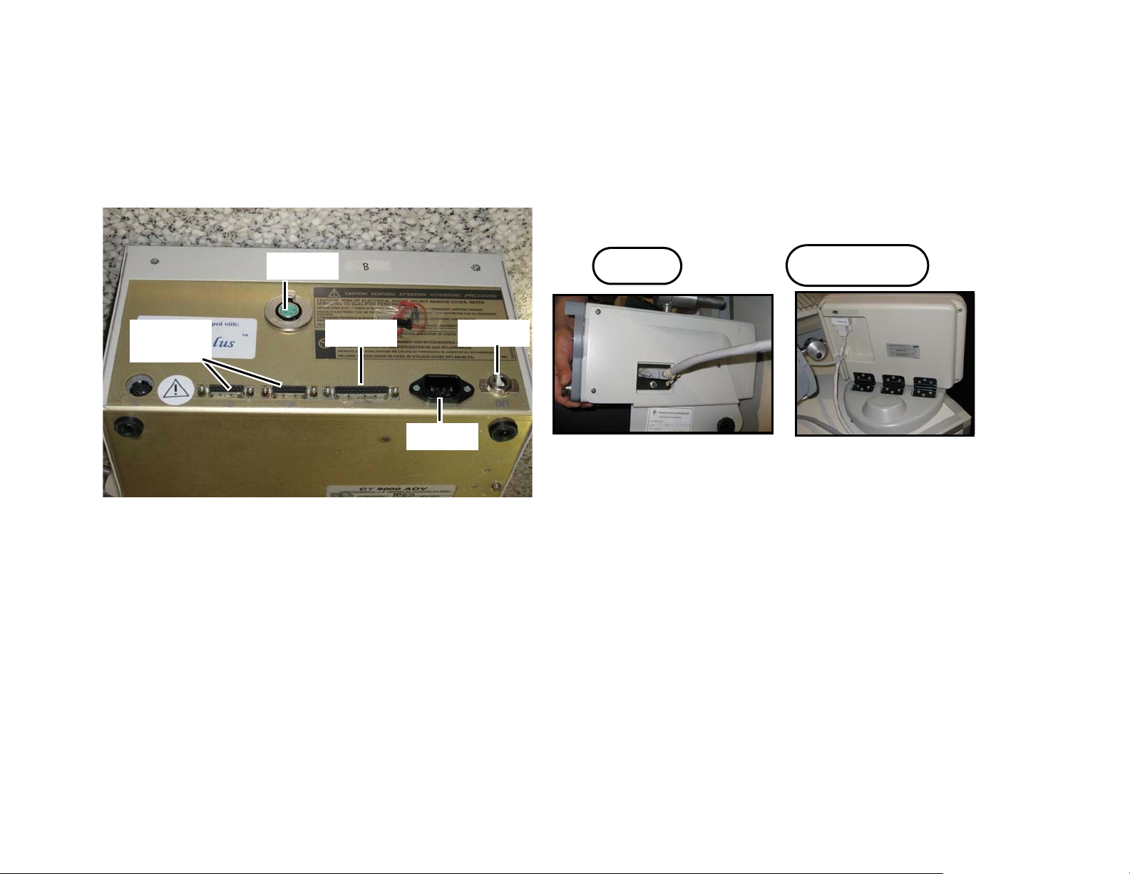
1.3.7 TYCO CT9000 ADV Injector
SetuptheTycoCT9000ADVinjectorasfollows:
1. ConnectthecablefromthePanelconnectortotheRemotePanel.
2. ConnectthecablefromtheInjectorconnectortotheInjector.
Figure 14:
Figure 13: ConnectorDetail
459800863451RevisionA CSIP Level 1WARNING: THIS PAGE CONTAINS COPYR IGHTED MATERIALS THAT ARE CONFIDENTIAL AND OR PROPRIETARY. ANY RELEASE OR DISTRIBUTION O F THIS MATERIAL, WITHOUT PERMISSION, IS A VIOLATION OF LAW. 25
Page 26
AccessCTSASInstallationInstructions SAS(SpiralAutoStart)Option
Power
Remote Control
Injector
X2 Connector
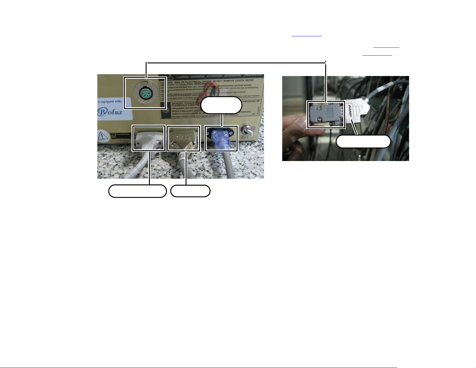
3. ConnectthePowercableoftheRemoteControlunit(seeFigure 15).
4. ConnecttheInterfacecablebetweentheX2connectorfromX1‐0475connector(seeFigure 2)onthe
ConsoleInterfaceBoardandtheRemoteControlunitUniversalconnector(seeFigure 15).
459800863451RevisionA CSIP Level 1WARNING: THIS PAGE CONTAINS COPYR IGHTED MATERIALS THAT ARE CONFIDENTIAL AND OR PROPRIETARY. ANY RELEASE OR DISTRIBUTION O F THIS MATERIAL, WITHOUT PERMISSION, IS A VIOLATION OF LAW. 26
Figure 15: CableConnection
Page 27

AccessCTSASInstallationInstructions SAS(SpiralAutoStart)Option
Universal Interface
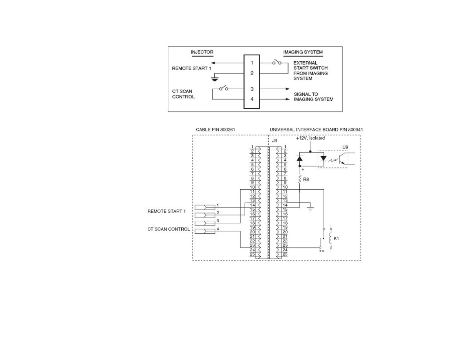
Theuniversalinterfaceconnectstheinjectortoanimagingsystem.Theimagingsystemcantriggerthe
injectortostartbyclosingaswitchbetweenpinsJ3‐13andJ3‐14oftheuniversalinterfaceconnectors,
whenthegroundfromJ3‐13isappliedtoJ3‐14,thesignalcalledRemoteStart1isdrivenlowandturnson
signalonU4pin42(seeFigure 16).
Themainprocessordetectsthissignalandinitiatesaninjection.However,ifascandelayhasbeen
programmedintotheconsoleprocessorfromtheselectedprotocol,thenthemainprocessorsendsan
outputatU4pin31topin1ofinverterU2.Whenthescandelayhasexpired,theinjectorenergizesrelay
459800863451RevisionA CSIP Level 1WARNING: THIS PAGE CONTAINS COPYR IGHTED MATERIALS THAT ARE CONFIDENTIAL AND OR PROPRIETARY. ANY RELEASE OR DISTRIBUTION O F THIS MATERIAL, WITHOUT PERMISSION, IS A VIOLATION OF LAW. 27
Page 28
AccessCTSASInstallationInstructions SAS(SpiralAutoStart)Option
K1(aCTScanControlSignal),whichprovidescontactclosure,allowingtheimagingsystemtostart
scanning.
Figure 16: UniversalInterfaceConnections
Figure 17: UniversalInterfaceConnections(indetail)
459800863451RevisionA CSIP Level 1WARNING: THIS PAGE CONTAINS COPYR IGHTED MATERIALS THAT ARE CONFIDENTIAL AND OR PROPRIETARY. ANY RELEASE OR DISTRIBUTION O F THIS MATERIAL, WITHOUT PERMISSION, IS A VIOLATION OF LAW. 28
Page 29
AccessCTSASInstallationInstructions SAS(SpiralAutoStart)Option
Injector
Head
Remote
Controller
PowerBox
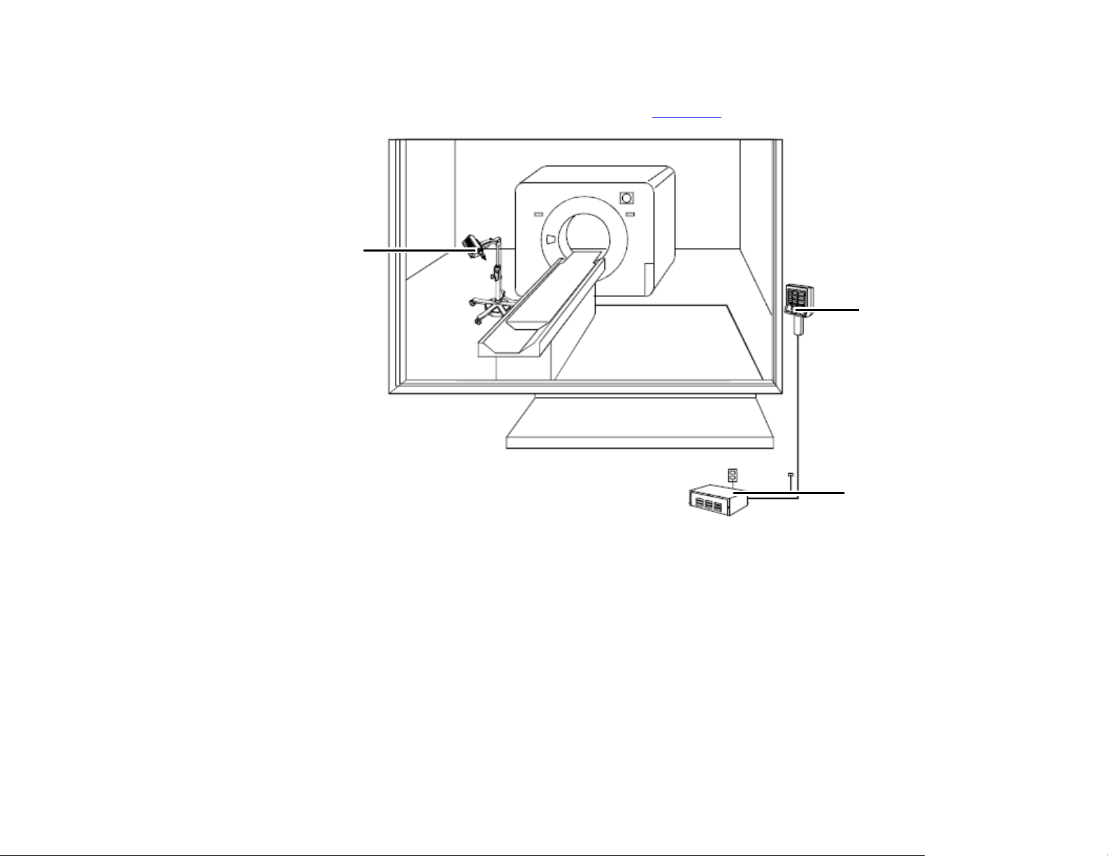
1.3.8 Optivantage Injector
OptivantageInjectorSysteminstallationSketchMap(seeFigure 18).
Figure 18:
459800863451RevisionA CSIP Level 1WARNING: THIS PAGE CONTAINS COPYR IGHTED MATERIALS THAT ARE CONFIDENTIAL AND OR PROPRIETARY. ANY RELEASE OR DISTRIBUTION O F THIS MATERIAL, WITHOUT PERMISSION, IS A VIOLATION OF LAW. 29
Page 30
AccessCTSASInstallationInstructions SAS(SpiralAutoStart)Option
Injector Connector
X2 Connector
ConnecttheinterfacecablebetweentheCTscannerandinjector(seeFigure 19andFigure 20).
a
Figure 19:
Figure 20:
X2Connector
1.3.9 Ulrich OHIO tandem XD 2002
ConnecttheinterfacecablebetweentheinjectorcontrollerandtheDB9terminal—X2connectorfromX1‐
0475connectorontheConsoleInterfaceBoard(seeFigure 22).
459800863451RevisionA CSIP Level 1WARNING: THIS PAGE CONTAINS COPYR IGHTED MATERIALS THAT ARE CONFIDENTIAL AND OR PROPRIETARY. ANY RELEASE OR DISTRIBUTION O F THIS MATERIAL, WITHOUT PERMISSION, IS A VIOLATION OF LAW. 30
Page 31
AccessCTSASInstallationInstructions SAS(SpiralAutoStart)Option
Injector Connector
Injector Connector
X2 Connector
Figure 21: InjectorConnectorOnUlrich
Figure 22: X2Connector
459800863451RevisionA CSIP Level 1WARNING: THIS PAGE CONTAINS COPYR IGHTED MATERIALS THAT ARE CONFIDENTIAL AND OR PROPRIETARY. ANY RELEASE OR DISTRIBUTION O F THIS MATERIAL, WITHOUT PERMISSION, IS A VIOLATION OF LAW. 31
Page 32
AccessCTSASInstallationInstructions InterfaceCablePinLayouts
A60 Injector
DB9 Male
Console Interface
DB9 Female
Appendix 2 Interface Cable Pin Layouts
2.1 Overview
ThisappendixprovidestheInterfaceCablePinLayoutforthevariousinjectorsdescribedinthismanual.
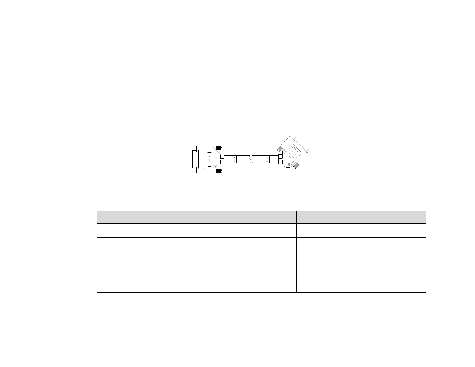
2.2 Nemoto Auto Enhanced CT Injector Cable
ThepinlayoutoftheNemotoAutoEnhancedCTInjectorcable(454110191561)W418:
Figure 23:
Table 3:
Pair # Point A X404 Point B X5-6017 Signal Name Color
1 1 1 Test_1 White
2 2 2 Test_2 Brown
3 5 5 Injector_IN Yellow
4 6 6 GND Green
Shell Shell Shield
459800863451RevisionA CSIP Level 1WARNING: THIS PAGE CONTAINS COPYR IGHTED MATERIALS THAT ARE CONFIDENTIAL AND OR PROPRIETARY. ANY RELEASE OR DISTRIBUTION O F THIS MATERIAL, WITHOUT PERMISSION, IS A VIOLATION OF LAW. 32
Page 33
AccessCTSASInstallationInstructions InterfaceCablePinLayouts
Console Interface
DB9 Female
Medrad Envision CT
injector DB37 Male
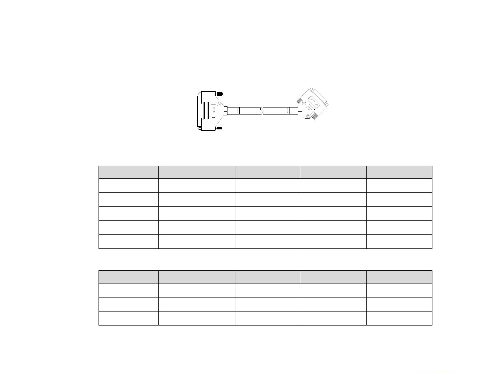
2.3 Medrad Envision CT Injector and Medrad Stellant D (SX) Injector Cable
ThepinlayoutoftheMedradEnvisionCTInjectorandMedradStellantD(SX)Injectorcable
(454110191571)W419:
Figure 24:
Table 4:
Pair # Point A X404 Point B X5-6017 Signal Name Color
10 5 White
459800863451RevisionA CSIP Level 1WARNING: THIS PAGE CONTAINS COPYR IGHTED MATERIALS THAT ARE CONFIDENTIAL AND OR PROPRIETARY. ANY RELEASE OR DISTRIBUTION O F THIS MATERIAL, WITHOUT PERMISSION, IS A VIOLATION OF LAW. 33
22 6 Brown
16 1 Green
25 2 Yellow
Shell Shell Shield
Table 5:
Pair # Point A X404 Point B X404 Signal Name Color
729 Blue
812 Blue
924 Blue
Page 34
AccessCTSASInstallationInstructions InterfaceCablePinLayouts
Medrad Vistron
Injector
DB25 Male
Console Interface
DB9 Female
Table 5:
Pair # Point A X404 Point B X404 Signal Name Color
11 30 Blue
17 27 Blue
18 23 Blue
23 33 Blue
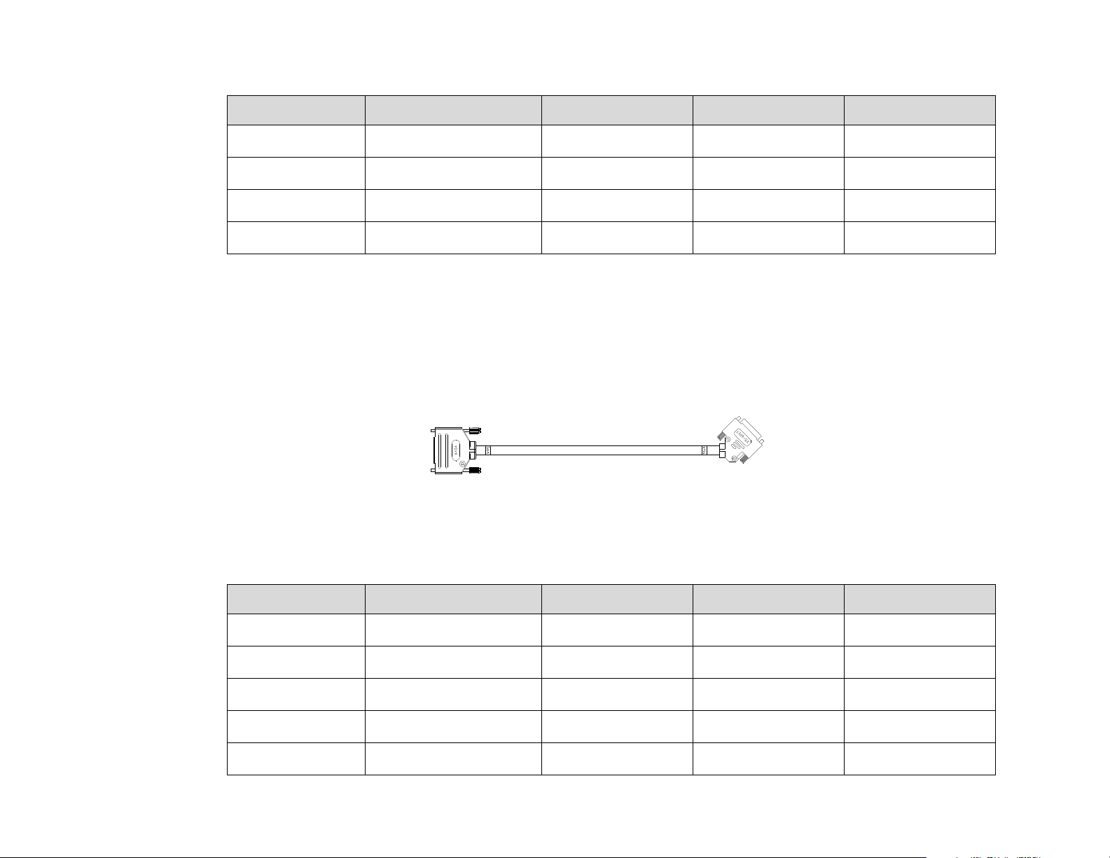
2.4 Medrad Vistron Injector Interface Cable
ThepinlayoutoftheMedradVistronInjectorcable(454110191671)W421:
Figure 25:
Table 6:
Pair # Point A X404 Point B X5-6017 Signal Name Color
3 1 Test_1 White
4 2 Test_2 Brown
8 5 Injector_IN Yellow
9 6 GND Green
Shell Shield
459800863451RevisionA CSIP Level 1WARNING: THIS PAGE CONTAINS COPYR IGHTED MATERIALS THAT ARE CONFIDENTIAL AND OR PROPRIETARY. ANY RELEASE OR DISTRIBUTION O F THIS MATERIAL, WITHOUT PERMISSION, IS A VIOLATION OF LAW. 34
Page 35
AccessCTSASInstallationInstructions InterfaceCablePinLayouts
ygj()
Console Interface
DB9 Femal
e
Tyco CT9000 ADV
Di
gital Injector
Table 7:
Pair # Point A X404 Point B X404 Signal Name Color
11 20 Blue
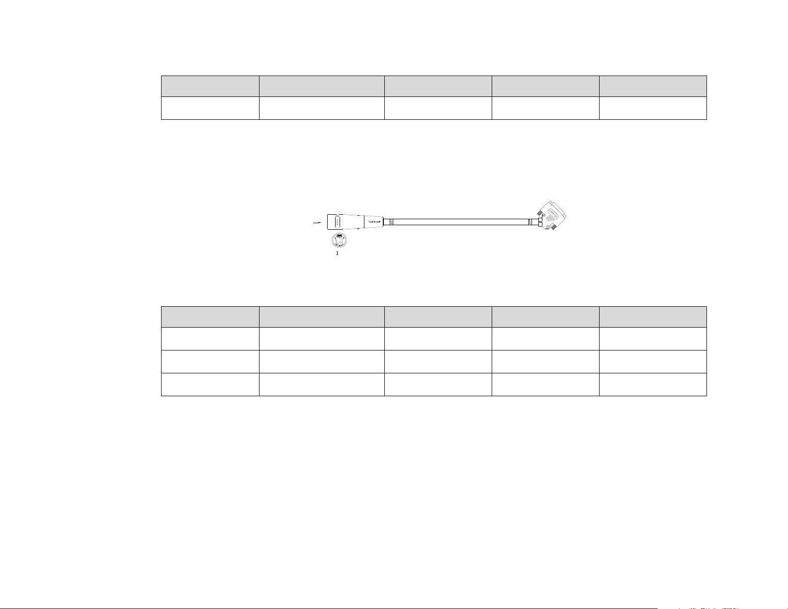
2.5 Tyco CT9000 ADV Digital Injector Interface Cable
ThepinlayoutoftheMedradVistronInjectorcable(454110191681)W422:
Figure 26:
Table 8:
Pair # Point A X404 Point B X5-6017 Signal Name Color
1 3 5 Injector_IN White
24 6 GNDBrown
459800863451RevisionA CSIP Level 1WARNING: THIS PAGE CONTAINS COPYR IGHTED MATERIALS THAT ARE CONFIDENTIAL AND OR PROPRIETARY. ANY RELEASE OR DISTRIBUTION O F THIS MATERIAL, WITHOUT PERMISSION, IS A VIOLATION OF LAW. 35
Shell Shield
Page 36
AccessCTSASInstallationInstructions InterfaceCablePinLayouts
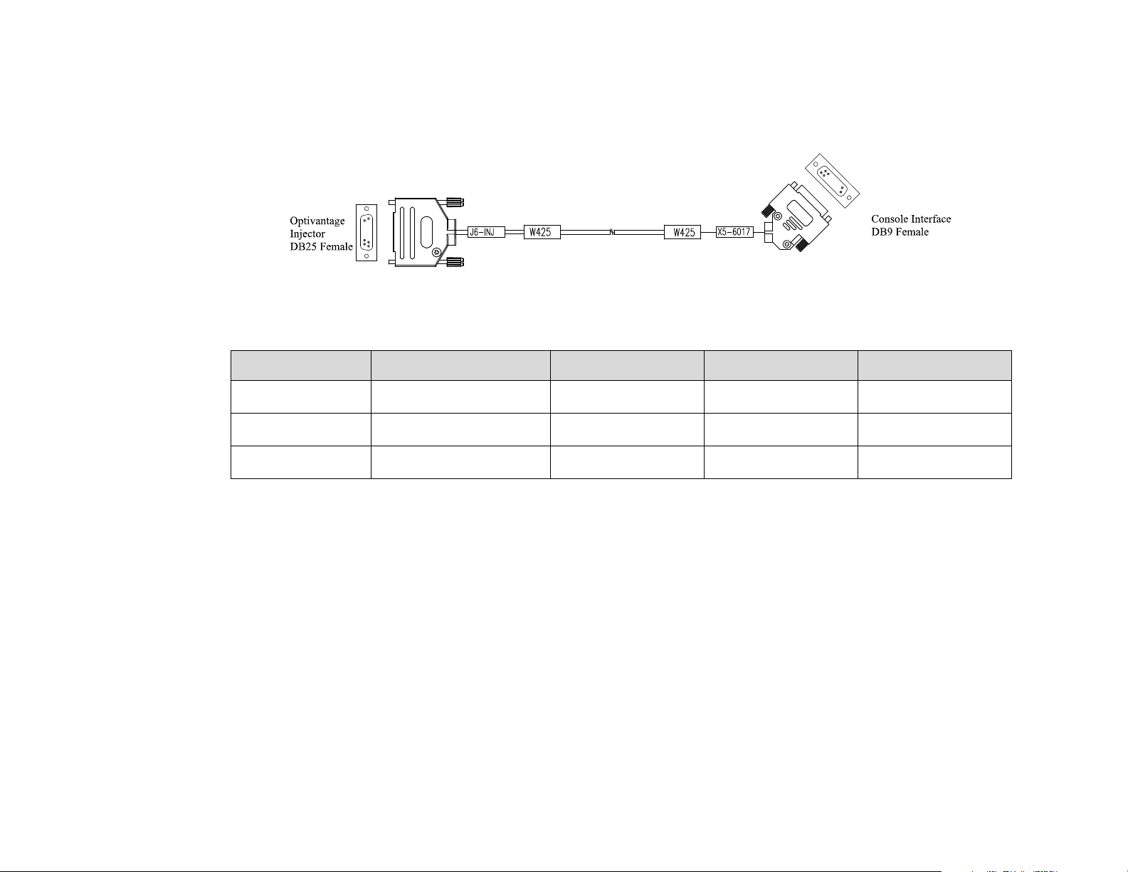
2.6 Optivantage Injector Interface Cable
ThepinlayoutoftheOptivanageInjectorcable(454110124241)W425:
Figure 27:
Table 9:
Pair # Point A J6 Point B X5-6017 Signal Name Color
4 5 Injector_IN White
56GNDBrown
Shell Shield
459800863451RevisionA CSIP Level 1WARNING: THIS PAGE CONTAINS COPYR IGHTED MATERIALS THAT ARE CONFIDENTIAL AND OR PROPRIETARY. ANY RELEASE OR DISTRIBUTION O F THIS MATERIAL, WITHOUT PERMISSION, IS A VIOLATION OF LAW. 36
Page 37
AccessCTSASInstallationInstructions InterfaceCablePinLayouts
ConsoleInterfaceDB9Femal
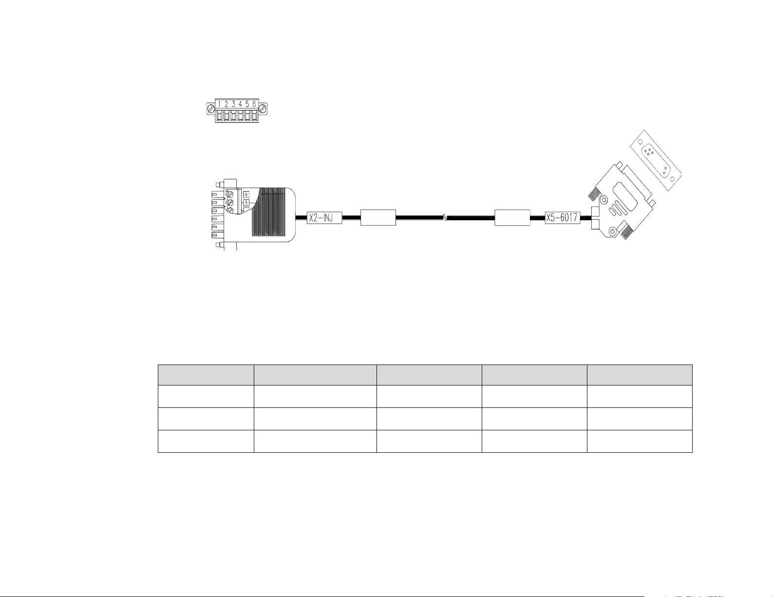
2.7 Ulrich Injector Interface Cable
ThepinlayoutoftheOptivanageInjectorcable(454110415861)W427:
Figure 28:
Table 10:
Pair # Point A X2-INJ Point B X5-6017 Signal Name Color
4 5 Injector_IN White
56GNDBrown
Shell Shield
459800863451RevisionA CSIP Level 1WARNING: THIS PAGE CONTAINS COPYR IGHTED MATERIALS THAT ARE CONFIDENTIAL AND OR PROPRIETARY. ANY RELEASE OR DISTRIBUTION O F THIS MATERIAL, WITHOUT PERMISSION, IS A VIOLATION OF LAW. 37
 Loading...