

Philips 9896 010 2216, 9896 010 2217, 9896 010 2223, 9896 010 2224 User manual

FILING INSTRUCTIONS
File this document in the binder
− RAD: BuckyDiagnost SYSTEM MANUAL
− − URF: DuoDiagnost SYSTEM MANUAL
URF: OmniDiagnost SYSTEM MANUAL
SERVICE MANUAL
NICOL Beam Limiting Device
NICOL ... V2 Collimator
9896 010 22…
746 NICOL ... V2 Collimator - 9896 010 22…
9896 010 22… (04.0) 0.5
Copyright 2004 Philips Medical Systems Nederland B.V.
ALL RIGHTS RESERVED
SERVICE MANUAL
NICOL X-Ray Beam Limiting Device
9896 010 2216.
9896 010 2217.
9896 010 2223.
9896 010 2224.
For serial numbers, see list of pages and drawings.
Copyright 2004 Philips Medical Systems Nederland B.V.
All rights are reserved. Reproduction in whole or in part is prohibited without the written consent of the copyright owner
Use of the information contained herein in any form and / or by any means whatsoever is strictly reserved for Philips and its licenses.
Use of this manual by unauthorized persons is strictly prohibited.
Printed in The Netherlands (04.0) 1
PMSN Best

X-Ray Beam Limting Device
SERVICE MANUAL - UNIT: NICOL X-Ray Beam Limiting Device
SYSTEM:
TYPE NO:.
9896 010 2216. NICOL RAD V2 Collimator
9896 010 2217. NICOL DuoD V2
Collimator
9896 010 2223. NICOL DuoD+iris V2 Collimator
9896 010 2224. NICOL OmniD V2 Collimator
Manual Code Number 4522 981 03586 Date: 17-03-2004
LIST OF PAGES and DRAWINGS
0.5 (04.0)
1 (04.0)
2
3 (04.0)
4
5 (04.0)
6 (04.0)
7 (04.0)
8 (04.0)
9 (04.0)
10 (04.0)
11 (04.0)
12 (04.0)
13 (04.0)
14 (04.0)
15 (04.0)
16 (04.0)
17 (04.0)
18 (04.0)
19 (04.0)
20 (04.0)
21 (04.0)
22 (04.0)
23 (04.0)
24 (04.0)
25 (04.0)
26 (04.0)
27 (04.0)
28 (04.0)
29 (04.0)
30 (04.0)
31 (04.0)
32 (04.0)
33 (04.0)
34 (04.0)
35 (04.0)
36 (04.0)
37 (04.0)
38 (04.0)
39 (04.0)
40 (04.0)
41 (04.0)
42 (04.0)
43 (04.0)
44 (04.0)
45 (04.0)
46 (04.0)
47 (04.0)
48 (04.0)
49 (04.0)
50 (04.0)
51 (04.0)
52 (04.0)
Z1-1 (03.0)
Z1-2 (03.0)
Z2-1 (03.0)
Z3-1 (03.0)
Z3-2 (03.0)
Z3-3 (03.0)
Z3-5 (03.0)
(04.0) 3
9896 010
2216.
2217.
2223.
2224.
Copyright 2004 Philips Medical systems Nederland B.V.
ALLRIGHTS RESERVED

Contents NICOL X-Ray Beam Limiting Device
Contents
1
INTRODUCTION AND TECHNICAL DATA..........................................................................................7
1.1 Introduction ...........................................................................................................................................7
1.2 Options..................................................................................................................................................7
1.3 Versions................................................................................................................................................8
1.4 Equipment Identification and Labelling..................................................................................................8
1.5 Tools .....................................................................................................................................................8
1.6 Technical Data......................................................................................................................................9
1.6.1 Compatibility......................................................................................................................................9
1.6.2 Mechanical Data..............................................................................................................................10
1.6.3 Electrical Data .................................................................................................................................10
1.6.4 Software Data..................................................................................................................................11
1.6.5 Environmental Conditions for Transport and Storage ......................................................................11
1.6.6 Performance Data ...........................................................................................................................12
1.7 Compliance information ......................................................................................................................13
1.8 Conditions of Acceptability ..................................................................................................................14
1.9 Abbreviations and definitions ..............................................................................................................14
1.10 Manual history .................................................................................................................................15
2
INSTALLATION..................................................................................................................................16
2.1 Introduction .........................................................................................................................................16
2.1.1 Tools & Test Equipment ..................................................................................................................16
2.1.2 Supplied Items.................................................................................................................................16
2.2 Installation instructions........................................................................................................................16
2.2.1 Mounting the coupling flange assembly Nicol V2.............................................................................17
2.2.2 Mounting the coupling flange assembly...........................................................................................18
2.2.3 Centering the BLD with respect to the X-Ray tube...........................................................................18
2.2.4 Mounting the BLD on the X-Ray tube housing.................................................................................19
2.2.5 Electrical installation........................................................................................................................20
2.2.6 Checking the alignment of the light field and the X-Ray field ...........................................................22
2.3 Options................................................................................................................................................22
2.3.1 Installation AEP-meter.....................................................................................................................22
3
FAULT FINDING.................................................................................................................................23
3.1 Introduction .........................................................................................................................................23
3.2 Faultfind Strategy................................................................................................................................24
3.3 Indicators ............................................................................................................................................24
3.3.1 LA2: Power Supply Converter CAN interface (PSC_CAN) ..............................................................24
3.3.2 LA3: Shutter Iris Filter Light Controller (SIFLCO).............................................................................25
3.3.3 Measuring Points.............................................................................................................................26
3.3.4 Miscellaneous..................................................................................................................................26
4
REPLACEMENTS ..............................................................................................................................28
4.1 General ...............................................................................................................................................28
4.2 Replace (complete) BLD on the stand.................................................................................................28
4.3 Replace Aesthetic Cover.....................................................................................................................28
(04.0) 5
9896 010
ALL RIGHTS RESERVED
2216.
2217.
2223.
2224.
Copyright © 2004 Philips Medical Systems Nederland B.V.

NICOL X-Ray Beam Limiting Device Contents
Replace Field Indication Plate.............................................................................................................28
4.4
4.5 Replace DSC Buttons .........................................................................................................................29
4.6 Replace DSC assembly ......................................................................................................................29
4.7 Replace LA2: PSC_CAN.....................................................................................................................31
4.8 Replace LA3: SIFLCO.........................................................................................................................32
4.8.1 Replace PROM LA3D17..................................................................................................................32
4.9 Replace Electronic Ruler.....................................................................................................................33
4.9.1 Connection electronic ruler..............................................................................................................34
4.10 Replace Mechanical Ruler...............................................................................................................35
4.11 Replace Lamp .................................................................................................................................36
4.12 Replace Micro-switch ......................................................................................................................37
4.13 Replace Micro-switch including Bracket...........................................................................................37
4.14 Replace Fan ....................................................................................................................................38
5
PROGRAMMING................................................................................................................................39
5.1 Introduction .........................................................................................................................................39
5.2 Hardware Programming ......................................................................................................................39
5.2.1 LA1: Backpanel ...............................................................................................................................39
5.2.2 LA2: Power Supply Converter & CAN Interface Board (PSC_CAN) ................................................39
5.3 Software Programming .......................................................................................................................39
6 ADJUSTMENTS .................................................................................................................................40
6.1 Centering the BLD with the X-Ray Tube .............................................................................................40
6.1.1 Introduction......................................................................................................................................40
6.1.2 Tools Required ................................................................................................................................40
6.1.3 Mounting the BLD Alignment Tool ...................................................................................................40
6.1.4 Checking the centering for PEI 9896 010 2216. ..............................................................................40
6.1.5 Adjusting the centring......................................................................................................................41
6.1.6 Checking the Centering for PEI’s 9896 010 2217., 9896 010 2223. and 9896 010 2224.................43
6.2 Field Indication Plate with Crossed-lines.............................................................................................44
6.3 X-Ray Field to Light Field....................................................................................................................45
6.3.1 Light Field Size Adjustment .............................................................................................................45
6.3.2 Lamp Adjustment After Replacing Lamp..........................................................................................45
6.3.3 Light Field Adjustment After Replacing Lamp ..................................................................................46
6.4 Electrical Adjustment...........................................................................................................................47
6.5 Software Adjustments .........................................................................................................................47
7
LIST OF FIGURES AND DRAWINGS................................................................................................48
P. PARTS LIST.......................................................................................................................................51
Z. DRAWINGS........................................................................................................................................52
6 (04.0)
ALL RIGHTS RESERVED
Copyright © 2004 Philips Medical Systems Nederland B.V.
9896 010
2216.
2217.
2223.
2224.

NICOL X-Ray Beam Limiting Device Introduction and Technical Data
1 INTRODUCTION AND TECHNICAL DATA
1.1 INTRODUCTION
This X-Ray Beam Limiting Device (BLD) is suitable for:
• RAD application 9896 010 2216. successor of 9896 010 22001
• RF applications with light and ruler 9896 010 2217. successor of 9896 010 22011
• RF applications as above plus filter and iris 9896 010 2223. successor of 9896 010 22091
• RF applications 9896 010 2224. successor of 9896 010 22101
The BLD, contains the following functions:
• Rectangular collimation, using rectangular shutters (main-, backup- and near focus shutters)
• Non rectangular collimation, using rectangular and iris shutters (iris on 9896 010 2223. and
9896 010 2224. only)
• Remotely controlled spectral filter (except for 9896 010 2217.)
• Light source (including field indication plate with crossed lines, fan and light ON button) for
simulating the X-Ray Field
• Electronic Ruler (9896 010 2216.) for automatic measuring the Source Image distance
• Mechanical Ruler (9896 010 2217. and 9896 010 2223. and 9896 010 2224.) for manually
measuring the Source Image distance
• Swivel range -45° to +45°, with lock position at 0°Manual control of rectangular shutters (DSC),
by means of 2 continuously rotatable buttons
• Accessory Rails
• Aesthetic cover
• Plug & Play interface to X-ray tube assembly (see chapter 1.6.1 Compatibility page 9)
1.2 OPTIONS
Possible options for this BLD are:
• 9896 010 22071 transparent AEP-meter
• 4522 300 2417x NICOL DISC
• 4522 300 2418x NICOL P&P DISC
downgrade to conventional interface to X-ray tube assemblies
for upgrading of Nicol to X-ray tube assemblies with P&P interface
1
1
1
see chapter 1.6.1 Compatibility page 9
(04.0) 7
9896 010
ALL RIGHTS RESERVED
2216.
2217.
2223.
2224.
Copyright © 2004 Philips Medical Systems Nederland B.V.

Introduction and Technical Data NICOL X-Ray Beam Limiting Device
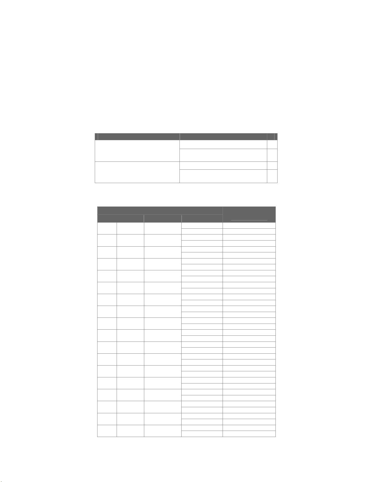
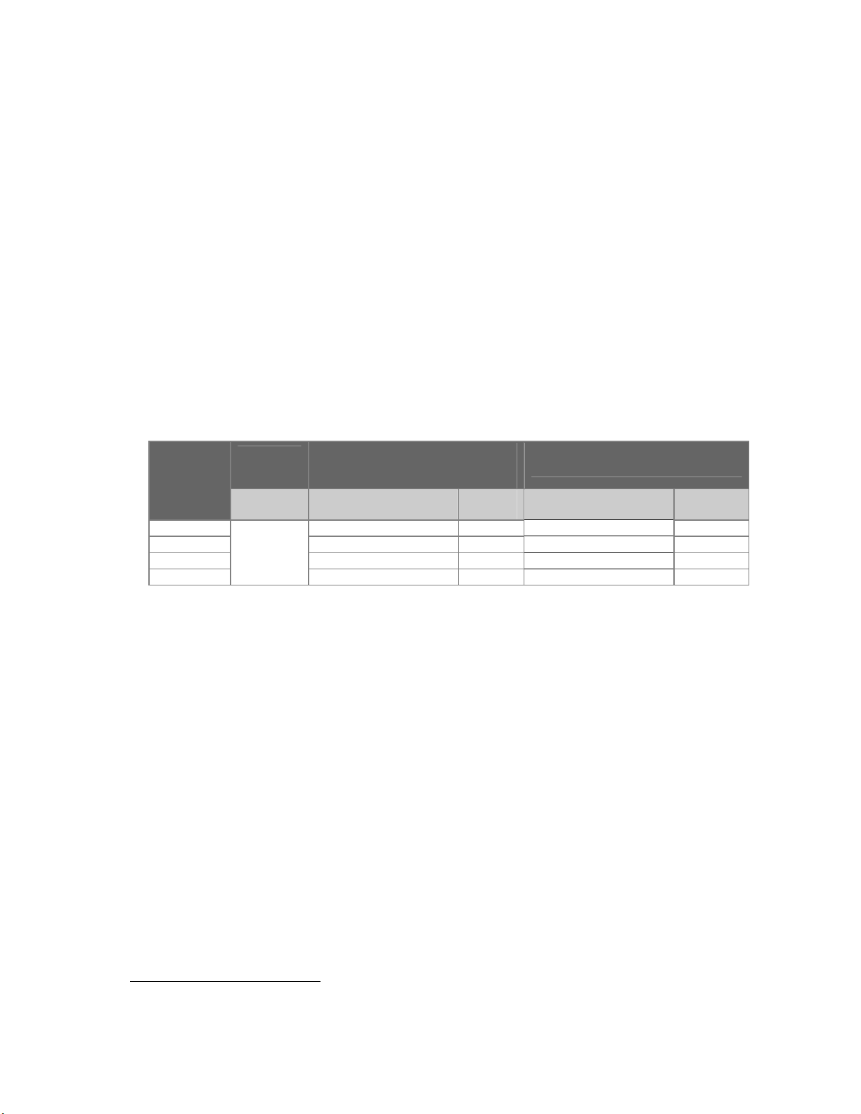
ERSIONS
1.3 V
Table 1: Version survey
Functions
Rectangular collimation
Non rectangular collimation - DSC buttons
Remote Controlled Spectral Filter
Light/Light-button + fan + Field Indication Plate
Electronic Ruler
Mechanical Ruler Swivel
Accessory rail
Aesthetic cover
Option: AEP-meter transparent
9896 010
2216.
5
5 5 5 5
5
5 5 5 5
5
5 5 5 5
5
5
5
9896 010
2217.
5
-
- - -
5 5 5
5
5
5
9896 010
2223.
5
5 5
5 5
5
5
5
9896 010
2224.
5
5
5
5
1.4 EQUIPMENT IDENTIFICATION AND LABELLING
The BLD identification labels are located at the rear of the BLD, see item 1, Figure 31, page 49.
1.5 TOOLS
For software tools see the applicable system reference manual. For hardware tools, see chapter 2.1.1,
Tools & Test Equipment, page 16.
8 (04.0)
ALL RIGHTS RESERVED
Copyright © 2004 Philips Medical Systems Nederland B.V.
9896 010
2216.
2217.
2223.
2224.
NICOL X-Ray Beam Limiting Device Introduction and Technical Data
ECHNICAL DATA
1.6 T
1.6.1 COMPATIBILITY
The BLD is compatible with:
X-Ray tube assemblies indicated in Table 3 in combination with NICOL Beam Limiting Devices as
configured in
• Table 2.
Table 2: Nicol configurations
Nicol Configurations With service kit
Nicol RAD 9896 010 22001
Nicol DuoD 9896 010 22011
Nicol DuoD+iris 9896 010 22091
Nicol OmniD 9896 010 22101
Nicol RAD V2 9896 010 2216.
Nicol DuoD V2 9896 010 2217.
Nicol DuoD+iris V2 9896 010 2223.
Nicol OmniD V2 9896 010 2224.
Table 3: Compatibility Overview
None A
NICOL P&P DISC 4522 300 2418x
None
NICOL DISC 4522 300 2417x
B
C
D
X-ray tube assembly
Tube Housing 12nc
MRC 200 0310 ROT-GS 1004
MRC 200 0407 ROT-GS 1004
MRC 200 0508 ROT-GS 1003
MRC 200 0508 ROT 1003
MRM 0410 ROT-GS 2502
MRM 0508 ROT-GS 2502
SRM 0608 ROT-GS 505
SRM 0511 ROT-GS 501
SRM 0612 ROT 501
SRO 33100 ROT 351
SRO 33100 ROT 350
SRM 2250 ROT-GS 500
SRM 2250 ROT-GS 504
SRM 0612 ROT 504
SRO 2550 ROT 350
SRO 0951 ROT 350
RO 1648 ROT 350
RO 1750 ROT 350
NICOL
configuration
9890 000 85091 A, D
9890 000 85092
9890 000 85101
9890 000 85102
9890 000 85141 A, D
9890 000 85142
9890 000 85131
9890 000 85132
9890 000 63271 A, D
9890 000 63272
9890 000 63261
9890 000 63262 B, C
9890 000 85181 A, D
9890 000 85182
9890 000 03821
9890 000 03822 B, C
9890 000 63911
9890 000 63912
9874 006 23112
9890 000 85851 B, C
9874 005 16122
9890 000 85841
9890 000 03841
9890 000 03842 B, C
9890 000 63841
9890 000 63842
9890 000 85001
9890 000 85002 B, C
9874 004 23122
9890 000 85831
9890 000 63181
9890 000 63182 B, C
9890 000 85301
9890 000 85302
9890 000 85281
9890 000 85282 B, C
B, C
A, D
B, C
B, C
A, D
B, C
B, C
A, D
B, C
A, D
A, D
B, C
A, D
A, D
B, C
A, D
A, D
B, C
A, D
A, D
B, C
A, D
A, D
B, C
A, D
(04.0) 9
9896 010
ALL RIGHTS RESERVED
2216.
2217.
2223.
2224.
Copyright © 2004 Philips Medical Systems Nederland B.V.
Introduction and Technical Data NICOL X-Ray Beam Limiting Device
• Bucky Diagnost TH and Digital Diagnost for 9896 010 2216.
• Duo Diagnost for 9896 010 2217. and 9896 010 2223.
• Omni Diagnost Eleva for 9896 010 2224.
• CAN-CMS CIA (ISO-CAN 2a) standard
NOTE
The compatibility list is subject to change without notice!
________________
1.6.2 MECHANICAL DATA
• tube housing interface : standard BLD coupling flange
• BLD coupling flange -focus distance : 64mm
• Dimensions and Weight : see Table 4
Table 4: Dimensions and weight
9896 010
2216.
9896 010
2217.
9896 010
2223.
9896 010
Dimensions (lxwxh) 38.2 x 28.2 x22.4 [cm3]
Packing dimensions 52 x 42 x 35 [cm3]
Net weight
Gross weight
± 130N ± 140N
± 160N ± 170N
1.6.3 ELECTRICAL DATA
• Power Supply interface : LA2X2 (see Table 5: Power Supply Interface)
Control interface : LA2X1/LA2X11 (see Table 6: CAN Interface)
•
protective earth interface : LAX100
•
Table 5: Power Supply Interface
LA2X2 Mnemonic Description Specification
1 +24V +24V
2 0V24 0V of +24V 1.5A
3 +12V +12V
4 0V12 0V of +12V 8.3A
SH Shield connected to housing
Connector-type: 4p. Mate-N-Lock
24V DC ± 20%
12.0V DC ± 0.1V
100W
2224.
10 (04.0)
ALL RIGHTS RESERVED
Copyright © 2004 Philips Medical Systems Nederland B.V.
9896 010
2216.
2217.
2223.
2224.
NICOL X-Ray Beam Limiting Device Introduction and Technical Data
Table 6: CAN Interface
LA2X1
LA2X11
Mnemonic Description
1 - reserved
2 CAN-L CAN-L bus line (dominant low)
3 0VCAN 0V of CAN supply voltage
4 - reserved
5 - reserved
6 0VCAN 0V of CAN supply voltage
7 CAN-H CAN-H bus line (dominant high)
8 RSTCAN Reset-line CAN
9 +12VCAN +12V CAN supply voltage
(I
= 150mA, I
max
= 30mA)
typ
SH Shield
connector-type: LA2X1 shielded 9-pole miniature sub-D connector male
LA2X11 shielded 9-pole miniature sub-D connector female
NOTE
The electrical cables are NOT included in the delivery
________________
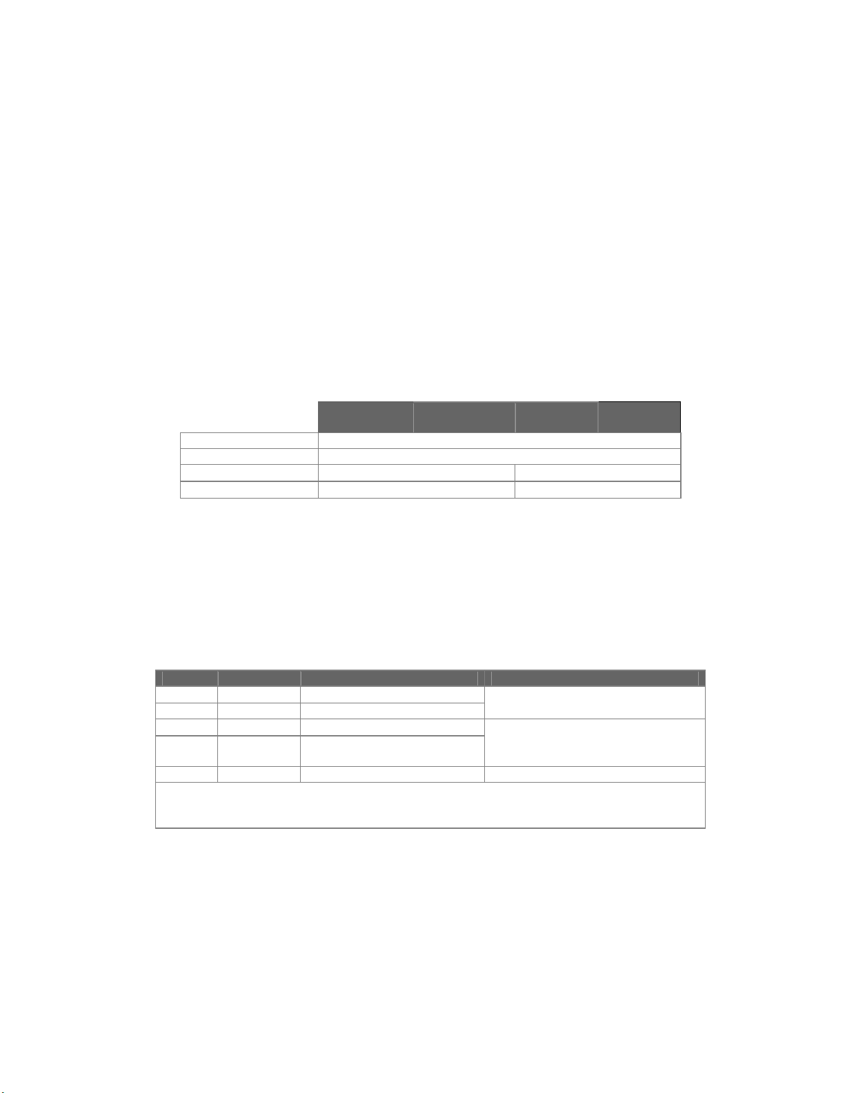
1.6.4 SOFTWARE DATA
The SW is located on a single PROM, see Table 7:
Item code number contains code number Location
NICOL RAD V2 9896 010 2216. 1 prom NICOL R1.3.1 4522 166 10705 LA3D17 see Z3-3
NICOL DuoD V2 9896 010 2217. 1 prom NICOL R1.3.1 4522 166 10705 LA3D17 see Z3-3
NICOL DuoD+iris V2 9896 010 2223. 1 prom NICOL R1.3.1 4522 166 10705 LA3D17 see Z3-3
NICOL OmniD V2 9896 010 2224. 1 prom NICOL R1.3.1 4522 166 10705 LA3D17 see Z3-3
Table 7: SW overview
NOTE
The SW release is subject to changes without notification!
________________
1.6.5 E
NVIRONMENTAL CONDITIONS FOR TRANSPORT AND STORAGE
• Ambient temperature range : -25 - +70 °C
• Relative humidity : 5 - 95 %
• Atmospheric pressure range : 70 - 110 kPa
(04.0) 11
9896 010
ALL RIGHTS RESERVED
2216.
2217.
2223.
2224.
Copyright © 2004 Philips Medical Systems Nederland B.V.
Introduction and Technical Data NICOL X-Ray Beam Limiting Device
1.6.6 P
ERFORMANCE DATA
Rectangular shutters
• two pairs of independent, symmetrically moving main shutters, 3mm thick lead (mechanically
coupled to backup shutters and near focus shutters)
• max. aperture : 2 x 14.4° (image receptor area 510mm at SID=100cm)
minimum field size : < 2 x 2 mm (at SID=100cm)
•
Iris
• 4 circular shaped iris segments, lead 3mm thick, in combination with the rectangular shutters
• max iris segment aperture : 18.8° (image receptor area 680mm at SID=100cm)
• max circular aperture : 14.4° (image receptor area 510mm at SID=100cm)
• minimum field size : 90mm (at SID=100cm)
Spectral Filter
• Remote controlled, discontinuous rotatable filter disk, containing four selectable filter positions.
For filter material and thickness, see Table 8: Filter material/position assignment.
• Filter switch time : < 350 ms (for adjacent filters)
< 700 ms (full range)
Table 8: Filter material/position assignment
9896 010 2216.
9896 010 2224.
9896 010 2223.
material Aleq
Filter
position
9896 010
2217.
material Aleq
@75kV
Position 0 no filter - no filter Position 1 1 mm Al + 0.1 mm Cu 4.0 mm 1 mm Al + 0.1 mm Cu 4.0 mm
Position 2 1 mm Al + 0.2 mm Cu 6.5 mm 1 mm Al + 0.2 mm Cu 6.5 mm
Position 3
No filter(s)
2 mm Al 2.0 mm 1 mm Al + 0.3 mm Cu 11.0 mm
Light
• Light source : 12V/100W halogen lamp
• Light intensity : > 193 lux (at SID=100 cm)
• X-Ray/Light Field accuracy : < 2% of SID in two directions
(including all X-Ray tube assembly tolerances)
< 2.5 mm (at SID = 100 cm for BLD only)
• Contrast ratio : > 4
• Maximum duty cycle : 80%, max. on time 8 min.
• Lamp on period : 5 - 60 s (SW programmable, accuracy ±0.1s)
• Lamp switch off
2
temp. : 75°C
Ruler
• Range : 30 - 205 cm
• Accuracy : 1.4 cm (at SID=70 cm)
: 4 cm (at SID=205 cm)
• Resolution : 1 mm
@75kV
2
When the BLD has reached a temperature of 75°C, the lamp is switched off automatically (SW-
controlled). It is no longer possible to switch on the lamp, until the temperature is <75°C.
12 (04.0)
ALL RIGHTS RESERVED
Copyright © 2004 Philips Medical Systems Nederland B.V.
9896 010
2216.
2217.
2223.
2224.

NICOL X-Ray Beam Limiting Device Introduction and Technical Data
Swivel
• Range : +/- 45°
• Accuracy : 0.1° at 0° lock position
General
• Leakage radiation : <43 cGy/hr (or < 50 mR/hr) at 100cm.
• Inherent filtration : 0.22m Al equivalent @ 75kV (spectral filter NOT included)
• Max. X-Ray tube voltage : 150 kV
• Max. X-Ray tube power : 500W (for 9896 010 2216., for any filter)
350W (for 9896 010 2217., 9896 010 2223.
and 9896 010 2224., any filter)
• Cold reset/warm reset : <30 s/<5 s
1.7 COMPLIANCE INFORMATION
Philips products comply with relevant international and national standards and laws. Information on
compliance will be supplied on request by your local PMS representative, or by:
Philips Medical Systems
PO Box 10.000
5680 DA Best
The Netherlands
Facsimile: +31 40 276 2205
Philips products comply with relevant international and national law and standards on EMC (ElectroMagnetic Compatibility) for this type of equipment when used as intended.
Such laws and standards define both the permissible electromagnetic emission levels from equipment
and its required immunity to electromagnetic interference from external sources.
• IEC 60601-1 "Medical electrical equipment. Part 1: General requirements for safety" (second edition 1988, including
amendment nr. 1 (1991), amendment nr. 2 (1995))
• IEC 60601-1-2 "Medical electrical equipment. Part 1: General requirements for safety. 2. Collateral Standard:
Electromagnetic compatibility - Requirements and tests" (second edition, 2001)
• IEC 60601-1-3 "Medical electrical equipment. Part 1: General requirements for safety. 3. Collateral Standard: General
requirements for radiation protection in diagnostic X-ray equipment" (first edition, 1994-07)
• IEC 60601-1-4 "Medical electrical equipment. Part 1: General requirements for safety. 4. Collateral Standard:
Programmable electrical medical systems" (first edition, 1996-05)
• UL 2601-1 "Medical electrical equipment, Part 1: General requirements for safety" (second edition, October 1997)
• CAN/CSA -C22.2 No. 601.1-M90 "Medical Electrical Equipment. Part 1: General requirements for safety" (November
1990, including Supplement C22.2 No. 601.1S1-94 and Amendment nr. 2 (1998))
• 21CFR, Subchapter J
•
IEC 60601-2-28 "Medical electrical equipment. Part 2: Particular requirements for the safety of X-ray source assemblies
and X-ray tube assemblies for medical diagnosis" (first edition, 03-1993)
(04.0) 13
9896 010
ALL RIGHTS RESERVED
2216.
2217.
2223.
2224.
Copyright © 2004 Philips Medical Systems Nederland B.V.

Introduction and Technical Data NICOL X-Ray Beam Limiting Device
ONDITIONS OF ACCEPTABILITY
1.8 C
The BLD is compatible with:
• X-ray tube assemblies, which meet the requirements as specified in the table below.
Leakage Radiation
≤ 0.43 mGy/h (≤ 50mR/h)
at conditions 150kV, 3mA and 100cm
distance.
Values of loading factors concerning leakage radiation
For RAD
<500 µSv/h
at conditions 150kV, 500W, 12000
mAs/h, 100cm distance.
For DuoD/DuoD+iris/OmniD <500 µSv/h
at conditions 150kV, 350W, 8400
mAs/h, 100cm distance
Inherent Filtration
≥2.5 mm Aleq
at conditions 150kV, 3mA
Distance Focus - Coupling Flange Interface Plane
64mm ± 2mm
• X-ray systems, which meet the requirements as specified in the table below.
Misalignment of the edges of the of visually defined Field with
≤ 1% of SID
the respective edges of the X-ray Field along either the length
or the width of the visually defined field.
Alignment of the centre of the radiographic X-ray Field with the
≤ 1.5% of SID
center of the image receptor
1.9 ABBREVIATIONS AND DEFINITIONS
Abbreviation Explanation
AEP Area Exposure Product
Aleq Aluminum equivalency
BLD Beam Limiting Device
DuoD Duo Diagnost
FRU Field Replaceable Unit
FSE Field Service Engineer
OmniD Omni Diagnost
PMS Philips Medical Systems
P&P Plug & Play
RAD Radiography
RF Radiography / Fluoroscopy
SID Source Image Distance
V2 Version 2
Protective Earth (ground)
14 (04.0)
ALL RIGHTS RESERVED
Copyright © 2004 Philips Medical Systems Nederland B.V.
9896 010
2216.
2217.
2223.
2224.

NICOL X-Ray Beam Limiting Device Introduction and Technical Data
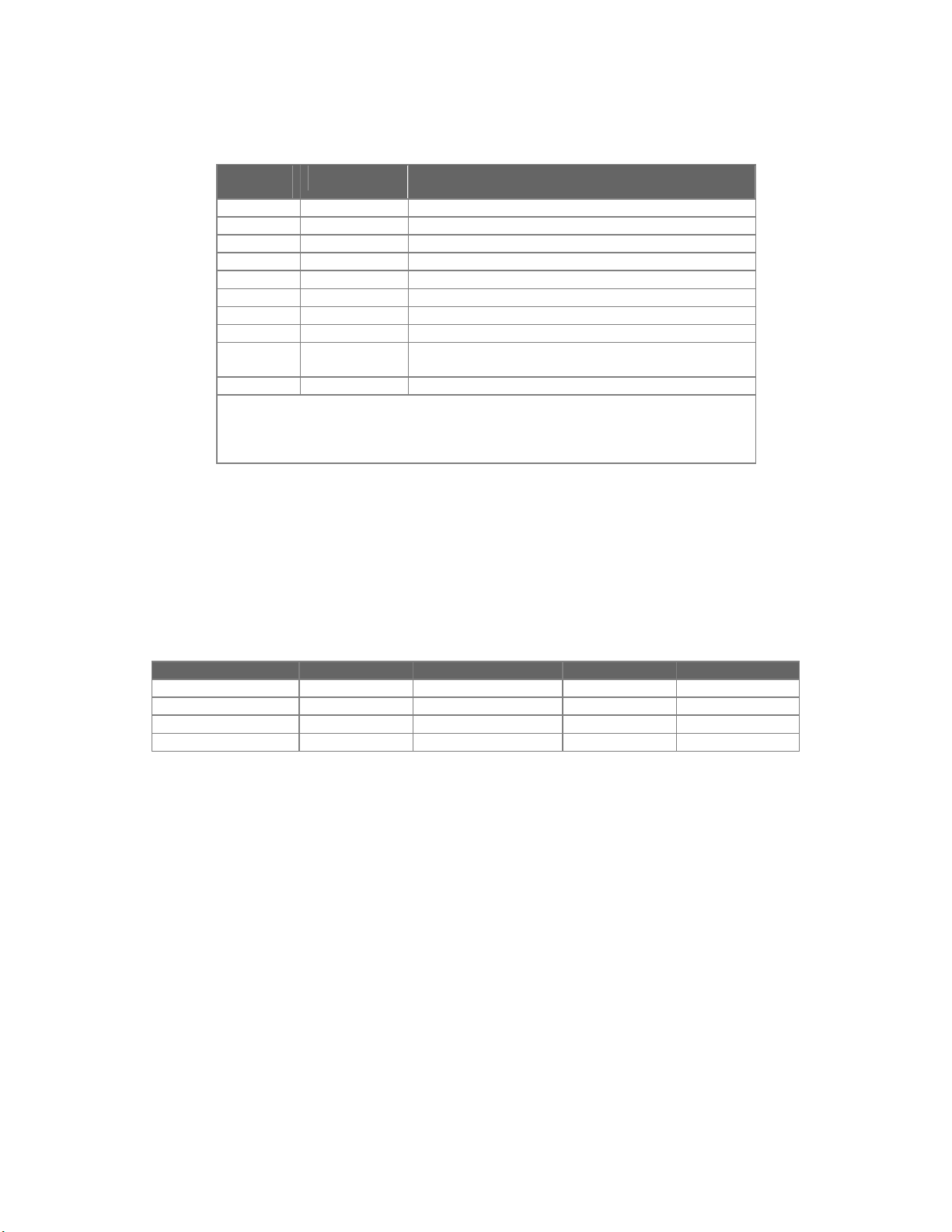
1.10 M
ANUAL HISTORY
Original Text : English
Date Version Name Reason of changes
19th June 1999 99.0 P.W.M. Sijbers First Version
9th September 1999 99.1 P.W.M. Sijbers
31st August 2000 00.0 P.W.M. Sijbers
31st October 2001 01.0 P.W.M. Sijbers
3rd December 2003 03.0 P.W.M. Sijbers
17th March 2004 04.0 P.W.M. Sijbers
• NICOL OmniD (9896 010 2224.) added.
• Chapter Conditions of Acceptability added.
• Document updated due to changed PEI-
numbers
• Chapter “1.6.1 Compatibility” extended for
new tubes and Nicol V2
• Chapter “2.2.1 Mounting the Coupling
Flange Nicol V2” added
(04.0) 15
9896 010
ALL RIGHTS RESERVED
2216.
2217.
2223.
2224.
Copyright © 2004 Philips Medical Systems Nederland B.V.

Installation NICOL X-Ray Beam Limiting Device
2 INSTALLATION
2.1 INTRODUCTION
This chapter contains general instructions about the installation of the BLD. For specific information at
system level, refer to the relevant system reference manual.
2.1.1 TOOLS & TEST EQUIPMENT
• Standard Service Toolkit
• BLD alignment tool, code number 4522 980 31521, available from Service Logistics Best.
2.1.2 S
The BLD is delivered as part of a pre-installed system or in a single package, always containing:
2.2 I
Whenever replacing a BLD, no centering is required, provided the coupling flange is left on the X-Ray
UPPLIED ITEMS
• BLD (including aesthetic cover)
• Coupling flange assembly (to mount and adjust the BLD on the X-Ray tube housing)
• Four countersunk screws (M6x25mm) (used for mounting the shipping bracket to the coupling
flange, also are intended to mount the coupling flange to the X-Ray tube housing)
• Service Manual (No Operator Manual supplied)
NSTALLATION INSTRUCTIONS
• Remove the items from the packing and check them against paragraph 2.1.2 Supplied Items,
for completeness.
• Install according sequence table below
NOTE
tube housing.
________________
1 Chapter 2.2.1 Chapter 2.2.2
2 - Chapter 2.2.3
3 Chapter 0 Chapter 0
4 Chapter 2.2.5 Chapter 2.2.5
5 Chapter 2.2.6 Chapter 2.2.6
Installation
NICOL V2
Table 9 Installation sequence
Installation NICOL V2
as replacement of NICOL
16 (04.0)
ALL RIGHTS RESERVED
Copyright © 2004 Philips Medical Systems Nederland B.V.
9896 010
2216.
2217.
2223.
2224.
NICOL X-Ray Beam Limiting Device Installation
2.2.1 M
OUNTING THE COUPLING FLANGE ASSEMBLY NICOL
V2
This chapter describes the mounting procedure in case a pre-aligned X-ray Tube Assembly is used.
• Unscrew the locking plate screw (item 5, Figure 3, page 19) from each of the two locking plates
(item 1, Figure 3) and push them outwards as far as possible.
• Remove the shipping bracket (item 2, Figure 3) together with the coupling flange (item 3, Figure
3) from the BLD
• Unscrew the shipping bracket from the coupling flange (countersunk screws M6 x 25 mm must
be reused to mount the coupling flange on the tube housing.)
NOTE
Check the screw required length (25 mm) in the applicable tube housing service documentation.
At least 5 mm must be screwed into the tube housing.
________________
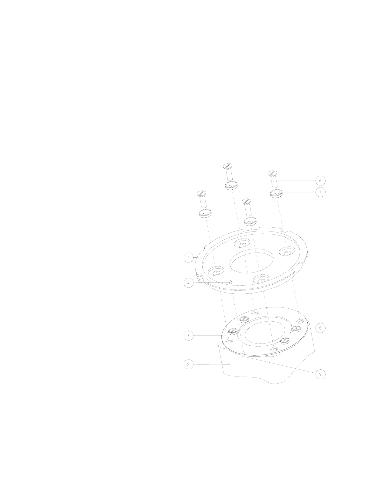
• Place the coupling flange (item 1,
Figure 1) on the X-Ray tube
housing (item 2, Figure 1) with
factory mounted alignment ring
(item 3, Figure 1)
• Positioning the reference pin (item
4, Figure 1) to the notch (item 5,
Figure 1) of the alignment ring.
Secure it with the four countersunk
•
screws M6 x 25 mm (item 6, Figure
1) and rings (item 7, Figure 1 )
• For screw length, see note above.
• Proceed with chapter 0 page 19.
CAUTION
Never loosen lacquered screws
(item 8, Figure 1. This will ruin the factory
alignment of the focus.
For realignment, the X-ray Source
assembly must be returned to Hamburg.
________________
Figure 1: Mounting the P&P coupling flange
(04.0) 17
9896 010
ALL RIGHTS RESERVED
2216.
2217.
2223.
2224.
Copyright © 2004 Philips Medical Systems Nederland B.V.
Installation NICOL X-Ray Beam Limiting Device
2.2.2 M
OUNTING THE COUPLING FLANGE ASSEMBLY
• Unscrew the locking plate screw (item 5, Figure 3, page 19) from each of the two locking plates
(item 1, Figure 3) and push them outwards as far as possible.
• Remove the shipping bracket (item 2, Figure 3) together with the coupling flange (item 3, Figure
3) from the BLD
• Unscrew the shipping bracket from the coupling flange (countersunk screws M6 x 25 mm must
be reused to mount the coupling flange on the tube housing.)
NOTE
Check the screw required length (25 mm) in the applicable tube housing service documentation.
At least 5 mm must be screwed into the tube housing.
________________
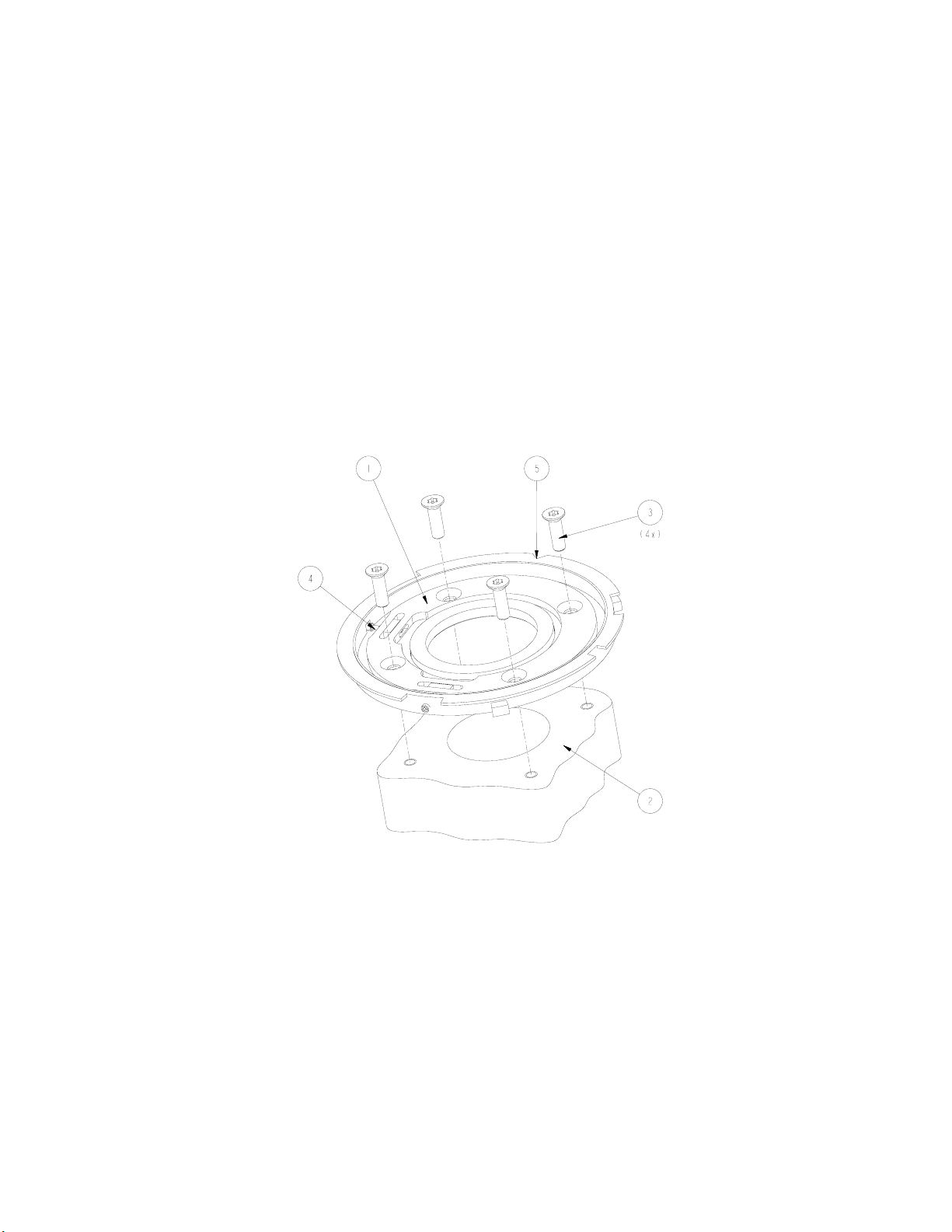
• Place the coupling flange (item 1, Figure 2) on the X-Ray tube housing (item 2, Figure 2),
positioning the 0° notch (item 5, Figure 2) to the rear of the X-Ray tube housing, and secure it
with the four countersunk screws M6 x 25 mm, item 3, Figure 2. (see note above)
Figure 2: Mounting the coupling flange assembly
2.2.3 CENTERING THE BLD WITH RESPECT TO THE X-RAY TUBE
All BLD functions have been accurately centered in the factory, relative to the central axis; any further
centering has to be done by adjusting the coupling flange assembly of the BLD with respect to the XRay focus. The specified alignment tool must be used.
The centering procedure is described in paragraph 6.1.4, page 40.
This procedure must be carried out:
• After replacement of NICOL DISC 4522 300 2417x
• After replacement of the X-Ray tube, configurations A and D of Table 3.
• NOT for replacements of NICOL and NICOL V2
18 (04.0)
ALL RIGHTS RESERVED
Copyright © 2004 Philips Medical Systems Nederland B.V.
9896 010
2216.
2217.
2223.
2224.
NICOL X-Ray Beam Limiting Device Installation
2.2.4 M
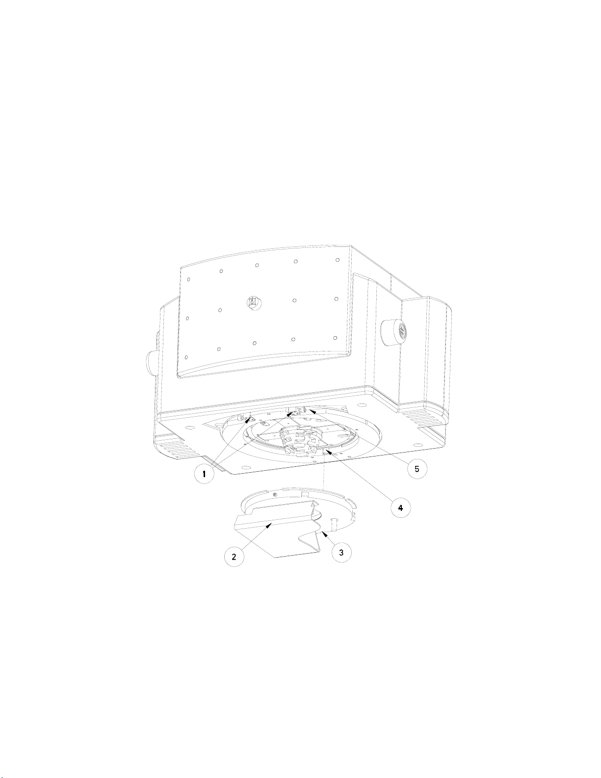
Carefully mount the BLD to the coupling flange, in order not to DAMAGE the near focus shutters!
OUNTING THE
• Slide the two locking plates (item 1, Figure 3) outwards as far as possible.
• Mount the BLD on the coupling flange assembly, with the 0° locking mechanism (item 4, Figure
3) to slide into the notch (item 3) of the coupling flange
• Slide the two locking plates inwards to their end stop
• Secure the two locking plates to the coupling plate with the two screws (item 5)
• Check whether the BLD is properly secured
BLD
ON THE
AY TUBE HOUSING
X-R
NOTE
________________
Figure 3: Mounting the BLD to the coupling flange
NOTE
It is strongly advised, to mount the BLD on the X-Ray tube housing without removing the aesthetic
covers first. This allows a better grip of the heavy BLD, and prevents damage to the ruler, when lifting
the BLD by holding the ruler by accident.
________________
(04.0) 19
9896 010
ALL RIGHTS RESERVED
2216.
2217.
2223.
2224.
Copyright © 2004 Philips Medical Systems Nederland B.V.
 Loading...