

Page 1

Philips C3 Patient Monitor
C3 Service Guide
Models: 862474, 862478
989803129451
Part Number 989803129451
Printed in the U.S.A. March 2003
Edition 1
Page 2

About this Manual
Proprietary Information
This document contains proprietary information, which is protected by copyright. All Rights
Reserved. Reproduction, adaptation, or translation without prior written permission is
prohibited, except as allowed under the copyright laws.
Philips Medical Systems
3000 Minuteman Road
Andover, MA 01810-1085
(978) 687-1501
Publication number
989803129451
Printed in USA
Warranty The information contained in this document is subject to change without notice.
Philips Medical Systems makes no warranty of any kind with regard to this material,
including, but not limited to, the implied warranties or merchantability and fitness for Philips
Medical Systems shall not be liable for errors contained herein or for incidental or
consequential damages in connection with the furnishing, performance, or use of this material.
Copyright Copyright © 2003 Philips Electronics North America Corporation
Microstream
®
is a registered trademark of Oridion Medical Inc.
Printing History
Additional Documents
New editions of this document incorporate all material updated since the previous edition.
Update packages may be issued between editions and contain replacement and additional
pages to be merged by a revision date at the bottom of the page. Pages that are rearranged due
to changes on a previous page are not considered revised.
The documentation printing date and part number indicate its current edition. The printing
date changes when a new edition is printed. (Minor corrections and updates that are
incorporated at reprint do not cause the date to change.) The document part number changes
when extensive technical changes are incorporated.
First Edition............................................................... March 2003
Use this document in conjunction with the C3 Instructions for Use guide (pn
989803228691).
ii
Page 3

Safety
All warnings, precautions and notes are located in the chapters that follow. You must read all
of this safety information before you begin monitoring with your C3 patient monitor.
Safety Standards
CE Marking
Europe The following products and accessories from Philips Medical Systems carry the CE mark
The C3 Patient Monitor is compliant with the following safety standards:
• UL 2601-1
• CAN/CSA C22.2 No. 601.1-M90
• EN60601-1
• EN60601-2-27
• EN60601-2-30
• EN60601-2-49
•EN865
to Council Directive 93/42/EEC.
0123
C3 Products: - 862474 - 862478
Accessories: - 21075A - 21076A - 21078A - 21090A
- M1837A - M4820A - M4818A
The following accessories from Philips Medical Systems carry one of the following CE
marks: or to Council Directive 93/42/EEC.
Accessories: - M1191A - M1192A - M1194A - M1941A
- 40493D - 40493E - M1980A - M1981A
- M1510A - M1550C - M1611A - M1613A
- M1615A - M1879A - M1878A - M1877A
- M1876A - M1875A - M1874A - M1576A
- M1575A - M1574A - M1573A - M1572A
- M1571A - M1577A - M1578A - M1579A
- 40401E - 40401D - 40401C - 40401B
- 40401A - M1598B - M1599B - M2526A
- M2525A - M2524A - M2528A - M2522A
- M2521A - M2520A - M1920A - M1922A
- M1921A - M4816A - M4817A
0366
Accessories from companies other than Philips Medical Systems carry CE markings
appropriate to the accessory.
Additional accessories not identified above fall outside the definition of a medical device.
The Former Agilent Technologies’ Healthcare Solutions Group is now a part of Philips
Medical Systems. Some accessories may still be branded with the Agilent name.
iii
Page 4

Authorized EU-representative: Philips Medizinsystems Böblingen GmbH, Hewlett Packard
Str., 71034, Böblingen Germany
Note
United States
Canada This ISM device complies with Canadian ICES-001.
United States Federal Law restricts this device to sale by or on the order of a physician.
Cet appareil ISM est conforme a la norme NMB-001 du Canada.
Philips Software License Terms
ATTENTION: USE OF THE SOFTWARE IS SUBJECT TO THE PHILIPS SOFTWARE LICENSE
TERMS SET FORTH BELOW. USING THE SOFTWARE INDICATES YOUR
ACCEPTANCE OF THESE LICENSE TERMS. IF YOU DO NOT ACCEPT THESE
LICENSE TERMS, YOU MAY RETURN THE SOFTWARE FOR A FULL REFUND. IF
THE SOFTWARE IS BUNDLED WITH ANOTHER PRODUCT, YOU MAY RETURN
THE ENTIRE UNUSED PRODUCT FOR A FULL REFUND.
PHILIPS SOFTWARE LICENSE TERMS
The following License Terms govern your use of the accompanying Software unless you have
a separate signed agreement with Philips Medical Systems.
License Grant. Philips Medical Systems grants you a license to Use one copy of the
Software. "Use" means storing, loading, installing, executing or displaying the Software. You
may not modify the Software or disable any licensing or control features of the Software. If
the Software is licensed for "concurrent use", you may not allow more than the maximum
number of authorized users to Use the Software concurrently.
Ownership. The Software is owned and copyrighted by Philips or its third party suppliers.
Your license confers no title to, or ownership in, the Software and is not a sale of any rights in
the Software. Philips’ third party suppliers may protect their rights in the event of any
violation of these License Terms.
Copies and Adaptations. You may only make copies or adaptations of the Software for
archival purposes or when copying or adaptation is an essential step in the authorized Use of
the Software. You must reproduce all copyright notices in the original Software on all copies
or adaptations. You may not copy the Software onto any public network.
No Disassembly or Decryption. You may not disassemble or decompile the Software unless
Philips prior written consent is obtained. In some jurisdictions, Philips consent may not be
required for limited disassembly or decompilation. Upon request, you will provide Philips
with reasonably detailed information regarding any disassembly or decompilation. You may
not decrypt the Software unless decryption is a necessary part of the operation of the
Software.
iv
Page 5

Transfer. Your license will automatically terminate upon any transfer of the Software. Upon
transfer, you must deliver the Software, including any copies and related documentation, to
the transferee. The transferee must accept these License Terms as a condition to the transfer.
Termination. Philips Medical Systems may terminate your license upon notice for failure to
comply with any of these License Terms. Upon termination, you must immediately destroy
the Software, together with all copies, adaptations and merged portions in any form.
Export Requirements. You may not export or re-export the Software or any copy or
adaptation in violation of any applicable laws or regulations.
U.S. Government Restricted Rights. The Software and any accompanying documentation
have been developed entirely at private expense. They are delivered and licensed as
"commercial computer software" as defined in DFARS 252.227-7013 (Oct. 1988), DFARS
252.211-7015 (May 1991) or DFARS 252.227-7014 (Jun. 1995), as a "commercial item" as
defined in FAR 2.101(a), or as "Restricted computer software" as defined in FAR 52.227-19
(Jun. 1987)(or any equivalent agency regulation or contract clause), whichever is applicable.
You have only those rights provided for such Software and any accompanying documentation
by the applicable FAR or DFARS clause or the Philips standard software agreement for the
product involved.
v
Page 6

Text
Conventions
The following conventions for Notes, Cautions, and Warnings are used in this manual.
WarningWarning
A Warning calls attention to a condition or possible situation that could cause injury to
the user and/or patient.
Caution
A Caution calls attention to a condition or possible situation that could damage or destroy the
product or the user’s work.
Note
A Note calls attention to an important point in the text.
Explanation of Symbols
Symbols on products and packaging mean the following. All symbols found in this section are
used this Instructions For Use guide.
Reference Number
Serial Number
0123
5% to 95% RH
CE Marking
Humidity
vi
Temperature Limits
Page 7
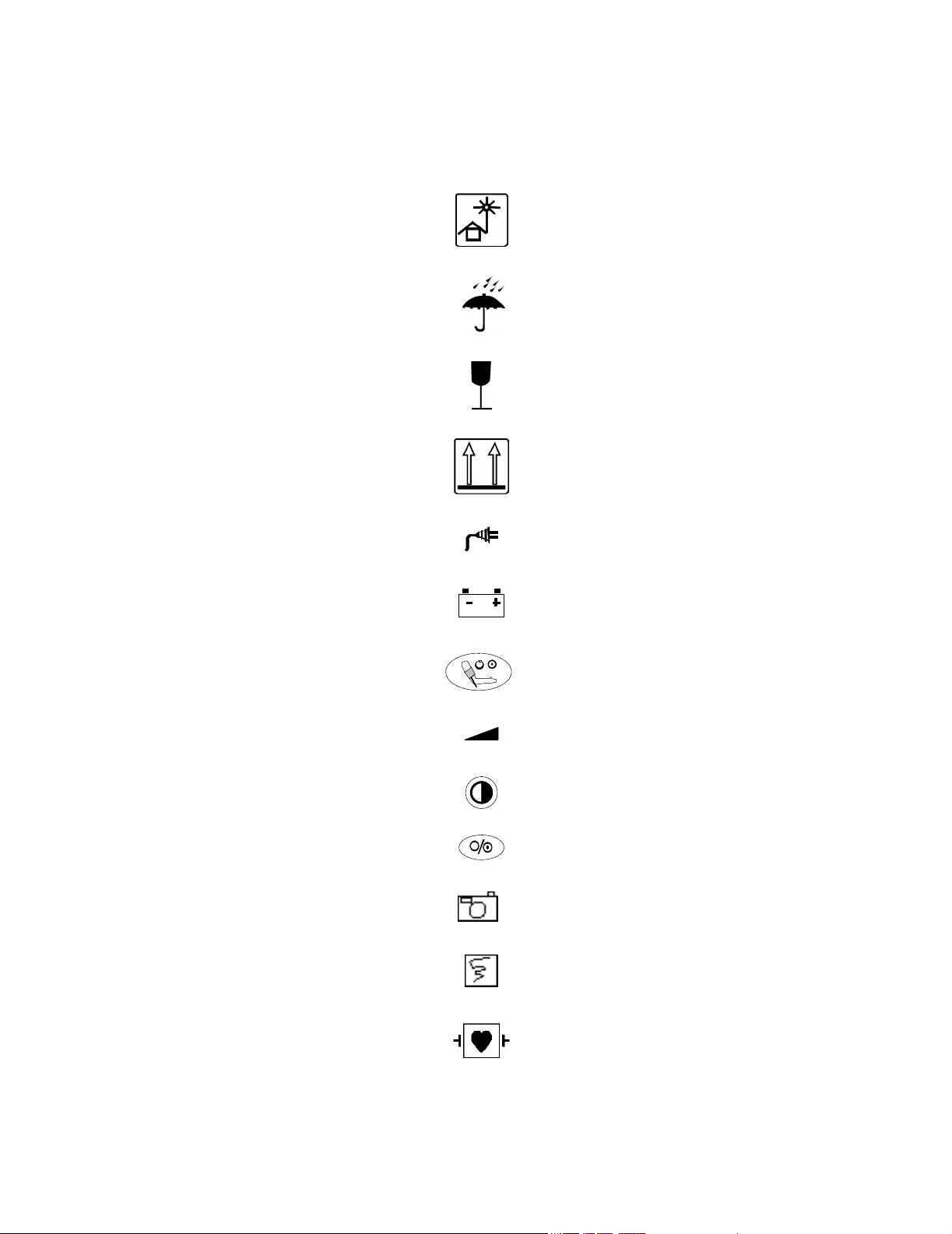
Keep out of Sun
Keep Dry
Fragile
Keep Upright
AC LED
Battery LED
NBP
Volume
Contrast
On/Standby
Snapshot
Continuous
Defibrillator-proof type CF equipment
vii
Page 8
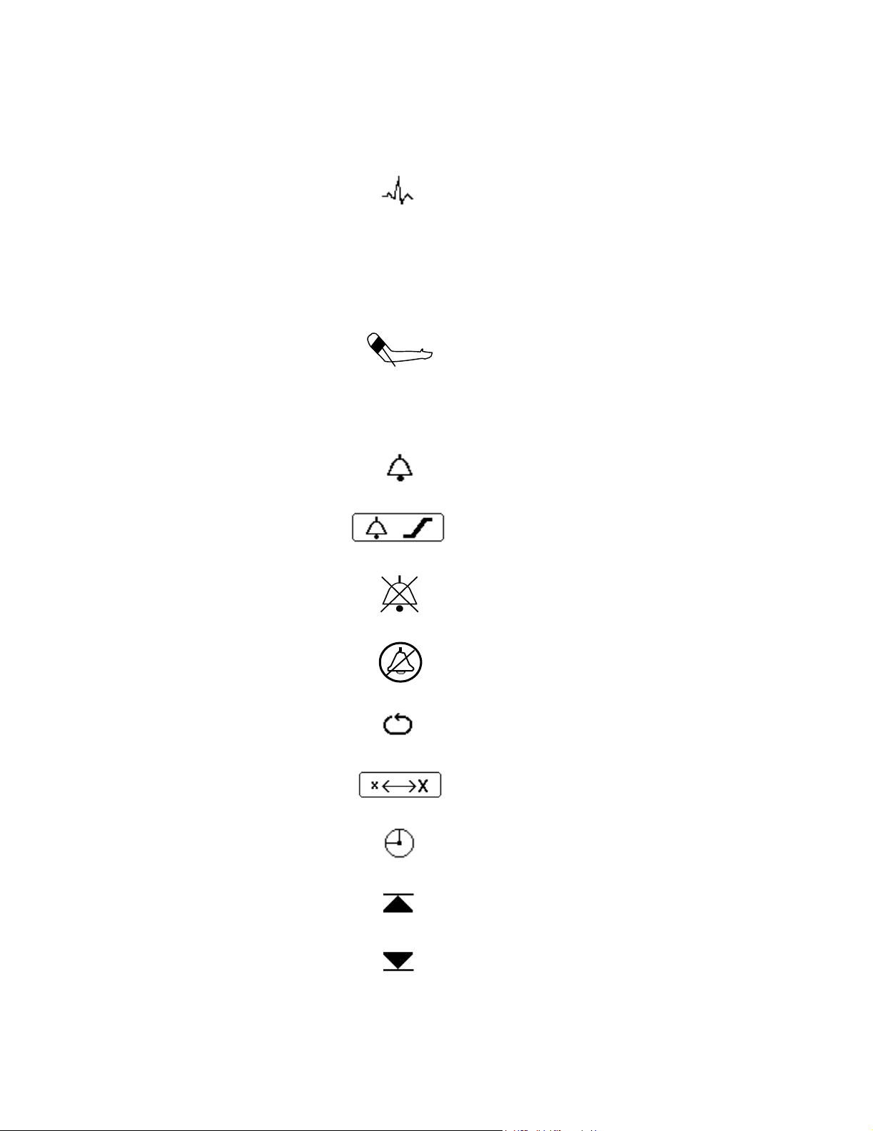
ECG
T
SpO
CO
2
2
Temperature
SpO
2
NBP
Carbon Dioxide
Alarm
Alarm Limits Menu
Audio Off
Silence/Reset
viii
NBP Automatic Interval Mode
Big Numbers
Clock
Up Alarm Arrow Limit
Down Alarm Arrow Limit
Page 9

Empty Battery
Perfusion Indicator Bar
Heart Rate
Powering Down
Heart Rate taken from ECG
Heart Rate taken from NBP
Heart Rate taken from SpO
Respiration
Stat Mode
Audio Pause
Setup Menu
ECG Size Bar
RF Interference
2
ix
Page 10
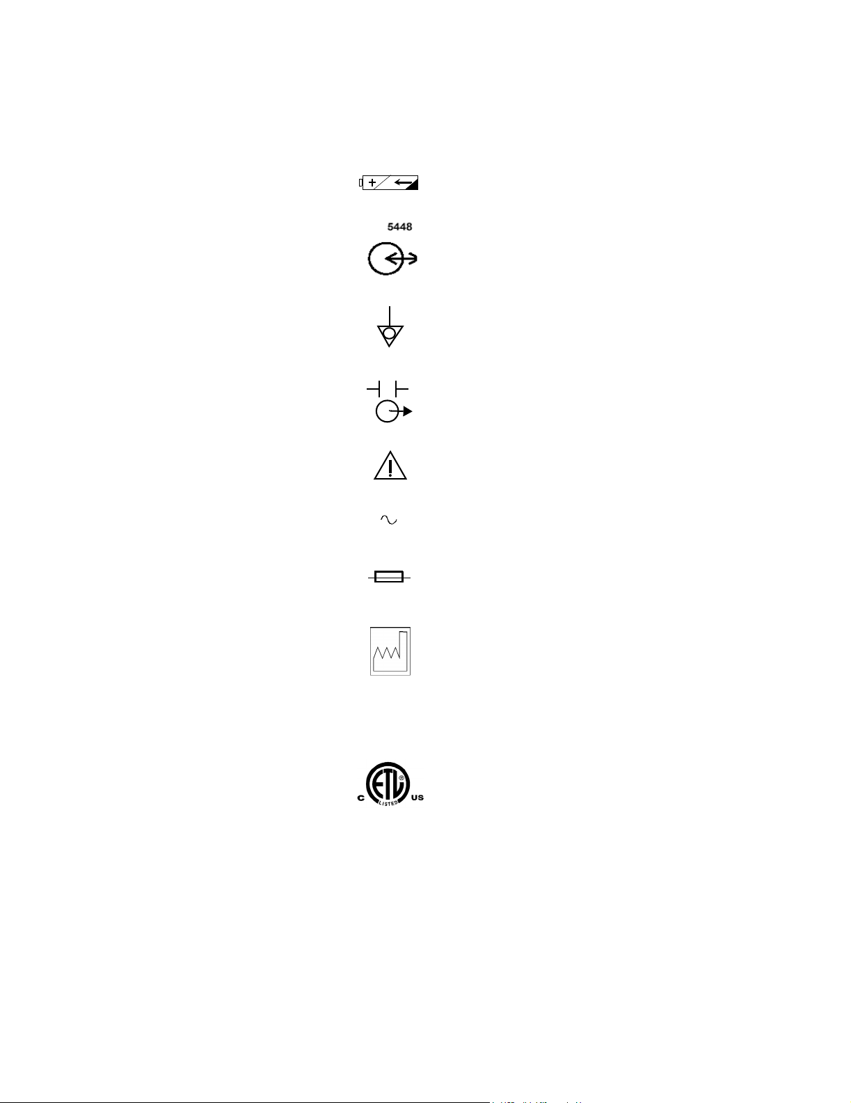
T1AL 250V
Battery Compartment
RS-232 I/O
Equipotential Grounding Post
Defib Sync
Attention, consult accompanying documents
Alternating Current
Fuse Type
x
YYYY-XX
IPX1
Date of Manufacture (Y= year; X = Month)
Drip-proof
ETL Mark
Page 11

Sales and Support Offices
Please call your local Philips Medical Systems sales office listed in your telephone directory,
or a Philips Medical Systems regional office listed below for the location of your nearest sales
office or for information on how to contact the Philips Response Center.
CORPORATE HEADQUARTERS:
Philips Medical Systems
Netherlands B.V.
Postbus 10.000
5680 DA Best
Netherlands
CORPORATE HEADQUARTERS:
Philips Medical Systems
3000 Minuteman Road
Andover, MA 01810
United States
(800) 934-7372
CANADA:
Philips Medical Systems Canada
281 Hillmount Road
Markham, ON
L6C 2S3
(800) 291-6743
EUROPE, MIDDLE EAST AND AFRICA:
Philips Medizinsysteme Böblingen GmbH
Cardiac and Monitoring Systems
Hewlett-Packard Str. 2
71034 Böblingen
Germany
Fax: (+49) 7031 463 1552
xi
Page 12

LATIN AMERICA HEADQUARTERS:
Philips Medical Systems
1550 Sawgrass Corporate Parkway #300
Sunrise, FL 33323
Telephone: 954-835 2600
Fax: 954-835-2626
ASIA PACIFIC HEADQUARTERS:
Philips Medical Systems
30/F Hopewell Centre
17 Kennedy Road
Wanchai
Hong Kong
Tel: (852) 2821 5888
Fax: (852) 2527 6727
xii
Page 13

Contents
1. Overview . . . . . . . . . . . . . . . . . . . . . . . . . . . . . . . . . . . . . . . . . . . . . . . . . . . . . . . 1-1
General Safety Information . . . . . . . . . . . . . . . . . . . . . . . . . . . . . . . . . . . . . . . . . . . . . . . . . . . . . .1-2
Introduction . . . . . . . . . . . . . . . . . . . . . . . . . . . . . . . . . . . . . . . . . . . . . . . . . . . . . . . . . . . . . . . . . .1-3
C3 Patient Monitor Description . . . . . . . . . . . . . . . . . . . . . . . . . . . . . . . . . . . . . . . . . . . . . . . . . . .1-3
Features and Options . . . . . . . . . . . . . . . . . . . . . . . . . . . . . . . . . . . . . . . . . . . . . . . . . . . . . . . . . . .1-4
Front Panel Description . . . . . . . . . . . . . . . . . . . . . . . . . . . . . . . . . . . . . . . . . . . . . . . . . . . . .1-4
Front of Monitor . . . . . . . . . . . . . . . . . . . . . . . . . . . . . . . . . . . . . . . . . . . . . . . . . . . . . . . . . . .1-5
Rear of Monitor . . . . . . . . . . . . . . . . . . . . . . . . . . . . . . . . . . . . . . . . . . . . . . . . . . . . . . . . . . .1-6
Screen Display . . . . . . . . . . . . . . . . . . . . . . . . . . . . . . . . . . . . . . . . . . . . . . . . . . . . . . . . . . . .1-7
Additional Documentation . . . . . . . . . . . . . . . . . . . . . . . . . . . . . . . . . . . . . . . . . . . . . . . . . . . . . .1-8
2. Site Preparations. . . . . . . . . . . . . . . . . . . . . . . . . . . . . . . . . . . . . . . . . . . . . . . . . 2-1
General Site Preparation Safety Information . . . . . . . . . . . . . . . . . . . . . . . . . . . . . . . . . . . . . . . . .2-2
Site Preparation Guidelines . . . . . . . . . . . . . . . . . . . . . . . . . . . . . . . . . . . . . . . . . . . . . . . . . . . . . .2-3
Warning, Cautions and Safety Precautions . . . . . . . . . . . . . . . . . . . . . . . . . . . . . . . . . . . . . . . . . .2-3
Patient Safety . . . . . . . . . . . . . . . . . . . . . . . . . . . . . . . . . . . . . . . . . . . . . . . . . . . . . . . . . . . . .2-3
Patient Leakage Current . . . . . . . . . . . . . . . . . . . . . . . . . . . . . . . . . . . . . . . . . . . . . . . . . . . . .2-3
Preparing to Use the Monitor. . . . . . . . . . . . . . . . . . . . . . . . . . . . . . . . . . . . . . . . . . . . . . . . . . . . .2-4
Power Source Requirements. . . . . . . . . . . . . . . . . . . . . . . . . . . . . . . . . . . . . . . . . . . . . . . . . .2-4
Protecting Against Electrical Shock . . . . . . . . . . . . . . . . . . . . . . . . . . . . . . . . . . . . . . . . . . . .2-4
Equipotential Grounding. . . . . . . . . . . . . . . . . . . . . . . . . . . . . . . . . . . . . . . . . . . . . . . . . . . . .2-4
Combining Equipment . . . . . . . . . . . . . . . . . . . . . . . . . . . . . . . . . . . . . . . . . . . . . . . . . . . . . .2-4
Disposing of the Monitor . . . . . . . . . . . . . . . . . . . . . . . . . . . . . . . . . . . . . . . . . . . . . . . . . . . .2-5
Unpacking the Monitor . . . . . . . . . . . . . . . . . . . . . . . . . . . . . . . . . . . . . . . . . . . . . . . . . . . . . . . . .2-5
Checking the Shipment . . . . . . . . . . . . . . . . . . . . . . . . . . . . . . . . . . . . . . . . . . . . . . . . . . . . . . . . .2-5
Returning System Components . . . . . . . . . . . . . . . . . . . . . . . . . . . . . . . . . . . . . . . . . . . . . . . . . . .2-6
Mounting . . . . . . . . . . . . . . . . . . . . . . . . . . . . . . . . . . . . . . . . . . . . . . . . . . . . . . . . . . . . . . . . . . . .2-7
Warnings, Cautions, and Safety Precautions Relating to Wall Mount Installation . . . . . . . . . . . .2-8
Mounting the GCX Wall Channel . . . . . . . . . . . . . . . . . . . . . . . . . . . . . . . . . . . . . . . . . . . . . . . . .2-9
Attaching the Mounting Plate to the Monitor . . . . . . . . . . . . . . . . . . . . . . . . . . . . . . . . . . . . . . . .2-9
Attaching the Monitor to the Wall Channel. . . . . . . . . . . . . . . . . . . . . . . . . . . . . . . . . . . . . . . . .2-10
Contents-1
Page 14

3. Maintaining the Monitor . . . . . . . . . . . . . . . . . . . . . . . . . . . . . . . . . . . . . . . . . . 3-1
Maintenance Safety Information. . . . . . . . . . . . . . . . . . . . . . . . . . . . . . . . . . . . . . . . . . . . . . . . . .3-2
Objectives . . . . . . . . . . . . . . . . . . . . . . . . . . . . . . . . . . . . . . . . . . . . . . . . . . . . . . . . . . . . . . . . . . . 3-3
Concepts . . . . . . . . . . . . . . . . . . . . . . . . . . . . . . . . . . . . . . . . . . . . . . . . . . . . . . . . . . . . . . . . . . . . 3-3
Light Maintenance . . . . . . . . . . . . . . . . . . . . . . . . . . . . . . . . . . . . . . . . . . . . . . . . . . . . . . . . . 3-3
Battery Conditioning . . . . . . . . . . . . . . . . . . . . . . . . . . . . . . . . . . . . . . . . . . . . . . . . . . . . . . . 3-3
Recommendations for Maintenance Frequency . . . . . . . . . . . . . . . . . . . . . . . . . . . . . . . . . . . . . . 3-4
Maintenance Checklist . . . . . . . . . . . . . . . . . . . . . . . . . . . . . . . . . . . . . . . . . . . . . . . . . . . . . . . . . 3-5
Inspecting the Monitor . . . . . . . . . . . . . . . . . . . . . . . . . . . . . . . . . . . . . . . . . . . . . . . . . . . . . . . . . 3-6
Inspecting the Cables and Cords . . . . . . . . . . . . . . . . . . . . . . . . . . . . . . . . . . . . . . . . . . . . . . . . . . 3-6
Cleaning . . . . . . . . . . . . . . . . . . . . . . . . . . . . . . . . . . . . . . . . . . . . . . . . . . . . . . . . . . . . . . . . . . . . 3-7
Battery Maintenance . . . . . . . . . . . . . . . . . . . . . . . . . . . . . . . . . . . . . . . . . . . . . . . . . . . . . . . . . . . 3-7
About the Battery . . . . . . . . . . . . . . . . . . . . . . . . . . . . . . . . . . . . . . . . . . . . . . . . . . . . . . . . . . 3-7
Battery Guidelines . . . . . . . . . . . . . . . . . . . . . . . . . . . . . . . . . . . . . . . . . . . . . . . . . . . . . . . . . 3-8
Checking the Battery Status. . . . . . . . . . . . . . . . . . . . . . . . . . . . . . . . . . . . . . . . . . . . . . . . . . 3-8
Identifying Battery Strength. . . . . . . . . . . . . . . . . . . . . . . . . . . . . . . . . . . . . . . . . . . . . . . . . . 3-9
Charging the Battery . . . . . . . . . . . . . . . . . . . . . . . . . . . . . . . . . . . . . . . . . . . . . . . . . . . . . . . 3-9
Conditioning a Battery . . . . . . . . . . . . . . . . . . . . . . . . . . . . . . . . . . . . . . . . . . . . . . . . . . . . . 3-10
Why is Battery Conditioning Necessary?. . . . . . . . . . . . . . . . . . . . . . . . . . . . . . . . . . . 3-10
When Should Battery Conditioning be Performed? . . . . . . . . . . . . . . . . . . . . . . . . . . . 3-10
How to Condition a Battery . . . . . . . . . . . . . . . . . . . . . . . . . . . . . . . . . . . . . . . . . . . . . 3-10
Battery INOP Messages . . . . . . . . . . . . . . . . . . . . . . . . . . . . . . . . . . . . . . . . . . . . . . . . . . . . 3-11
4. Testing the Monitor . . . . . . . . . . . . . . . . . . . . . . . . . . . . . . . . . . . . . . . . . . . . . . 4-1
Testing Safety Information . . . . . . . . . . . . . . . . . . . . . . . . . . . . . . . . . . . . . . . . . . . . . . . . . . . . . . 4-2
Objectives . . . . . . . . . . . . . . . . . . . . . . . . . . . . . . . . . . . . . . . . . . . . . . . . . . . . . . . . . . . . . . . . . . . 4-3
Concepts . . . . . . . . . . . . . . . . . . . . . . . . . . . . . . . . . . . . . . . . . . . . . . . . . . . . . . . . . . . . . . . . . . . . 4-3
Functionality Assurance. . . . . . . . . . . . . . . . . . . . . . . . . . . . . . . . . . . . . . . . . . . . . . . . . . . . .4-3
Preventative Maintenance . . . . . . . . . . . . . . . . . . . . . . . . . . . . . . . . . . . . . . . . . . . . . . . . . . . 4-3
Performance and Safety Tests . . . . . . . . . . . . . . . . . . . . . . . . . . . . . . . . . . . . . . . . . . . . . . . . 4-3
Testing Checklist. . . . . . . . . . . . . . . . . . . . . . . . . . . . . . . . . . . . . . . . . . . . . . . . . . . . . . . . . . . . . . 4-4
Test Reporting. . . . . . . . . . . . . . . . . . . . . . . . . . . . . . . . . . . . . . . . . . . . . . . . . . . . . . . . . . . . . . . . 4-5
Recommendations for Testing Frequency. . . . . . . . . . . . . . . . . . . . . . . . . . . . . . . . . . . . . . . . . . . 4-6
Test Map . . . . . . . . . . . . . . . . . . . . . . . . . . . . . . . . . . . . . . . . . . . . . . . . . . . . . . . . . . . . . . . . . . . . 4-7
Equipment . . . . . . . . . . . . . . . . . . . . . . . . . . . . . . . . . . . . . . . . . . . . . . . . . . . . . . . . . . . . . . . . . . . 4-8
Serial Numbers . . . . . . . . . . . . . . . . . . . . . . . . . . . . . . . . . . . . . . . . . . . . . . . . . . . . . . . . . . . . . . . 4-9
Passwords . . . . . . . . . . . . . . . . . . . . . . . . . . . . . . . . . . . . . . . . . . . . . . . . . . . . . . . . . . . . . . . . . . . 4-9
Visual Test. . . . . . . . . . . . . . . . . . . . . . . . . . . . . . . . . . . . . . . . . . . . . . . . . . . . . . . . . . . . . . . . . . 4-10
Power On Test. . . . . . . . . . . . . . . . . . . . . . . . . . . . . . . . . . . . . . . . . . . . . . . . . . . . . . . . . . . . . . . 4-10
Functionality Assurance Tests . . . . . . . . . . . . . . . . . . . . . . . . . . . . . . . . . . . . . . . . . . . . . . . . . .4-11
Contents-2
Page 15

Performance Assurance Test . . . . . . . . . . . . . . . . . . . . . . . . . . . . . . . . . . . . . . . . . . . . . . . .4-11
Power-On Self-Test . . . . . . . . . . . . . . . . . . . . . . . . . . . . . . . . . . . . . . . . . . . . . . . . . . . . . . .4-11
Alarm Test . . . . . . . . . . . . . . . . . . . . . . . . . . . . . . . . . . . . . . . . . . . . . . . . . . . . . . . . . . . . . .4-12
Volume Control Test . . . . . . . . . . . . . . . . . . . . . . . . . . . . . . . . . . . . . . . . . . . . . . . . . . . . . .4-12
Preventative Maintenance Tests. . . . . . . . . . . . . . . . . . . . . . . . . . . . . . . . . . . . . . . . . . . . . . . . . .4-14
Documenting NBP Test Results . . . . . . . . . . . . . . . . . . . . . . . . . . . . . . . . . . . . . . . . . . . . . .4-15
Pneumatic System Functionality . . . . . . . . . . . . . . . . . . . . . . . . . . . . . . . . . . . . . . . . . . . . .4-16
To Zero the Simulator . . . . . . . . . . . . . . . . . . . . . . . . . . . . . . . . . . . . . . . . . . . . . . . . . .4-16
Pressure Transducer Accuracy Test . . . . . . . . . . . . . . . . . . . . . . . . . . . . . . . . . . . . . . . .4-17
Pneumatic Leakage Test . . . . . . . . . . . . . . . . . . . . . . . . . . . . . . . . . . . . . . . . . . . . . . . .4-17
Inflation Rate Test . . . . . . . . . . . . . . . . . . . . . . . . . . . . . . . . . . . . . . . . . . . . . . . . . . . . .4-18
Over-Pressure Test . . . . . . . . . . . . . . . . . . . . . . . . . . . . . . . . . . . . . . . . . . . . . . . . . . . . .4-19
Deflation Rate Test . . . . . . . . . . . . . . . . . . . . . . . . . . . . . . . . . . . . . . . . . . . . . . . . . . . .4-20
Basic Pneumatic Leakage (BPL) Test . . . . . . . . . . . . . . . . . . . . . . . . . . . . . . . . . . . . . . . . .4-21
Performance Procedures . . . . . . . . . . . . . . . . . . . . . . . . . . . . . . . . . . . . . . . . . . . . . . . . . . . . . . .4-22
Battery Performance Test . . . . . . . . . . . . . . . . . . . . . . . . . . . . . . . . . . . . . . . . . . . . . . . . . . .4-22
Temperature Test . . . . . . . . . . . . . . . . . . . . . . . . . . . . . . . . . . . . . . . . . . . . . . . . . . . . . . . . .4-23
ECG/Respiration Performance . . . . . . . . . . . . . . . . . . . . . . . . . . . . . . . . . . . . . . . . . . . . . . .4-25
ECG Test. . . . . . . . . . . . . . . . . . . . . . . . . . . . . . . . . . . . . . . . . . . . . . . . . . . . . . . . . . . .4-25
Respiration Test . . . . . . . . . . . . . . . . . . . . . . . . . . . . . . . . . . . . . . . . . . . . . . . . . . . . . .4-26
SpO2 Performance . . . . . . . . . . . . . . . . . . . . . . . . . . . . . . . . . . . . . . . . . . . . . . . . . . . . . . . .4-27
Dynamic Operating Range Test . . . . . . . . . . . . . . . . . . . . . . . . . . . . . . . . . . . . . . . . . . .4-27
LED Excitation Test . . . . . . . . . . . . . . . . . . . . . . . . . . . . . . . . . . . . . . . . . . . . . . . . . . .4-28
CO2 Performance . . . . . . . . . . . . . . . . . . . . . . . . . . . . . . . . . . . . . . . . . . . . . . . . . . . . . . . . .4-29
Documenting CO2 Test Results . . . . . . . . . . . . . . . . . . . . . . . . . . . . . . . . . . . . . . . . . . . . . .4-30
Barometric Pressure Check and Calibration . . . . . . . . . . . . . . . . . . . . . . . . . . . . . . . . .4-31
Leakage Check. . . . . . . . . . . . . . . . . . . . . . . . . . . . . . . . . . . . . . . . . . . . . . . . . . . . . . . .4-32
Pump Check. . . . . . . . . . . . . . . . . . . . . . . . . . . . . . . . . . . . . . . . . . . . . . . . . . . . . . . . . .4-33
Flow Rate Check and Calibration . . . . . . . . . . . . . . . . . . . . . . . . . . . . . . . . . . . . . . . . .4-33
CO2 Gas Measurement Calibration Check. . . . . . . . . . . . . . . . . . . . . . . . . . . . . . . . . .4-34
Calibration Verification . . . . . . . . . . . . . . . . . . . . . . . . . . . . . . . . . . . . . . . . . . . . . . . . .4-35
Reset Pump Operating Time Counters . . . . . . . . . . . . . . . . . . . . . . . . . . . . . . . . . . . . .4-35
Serial Interface and Nurse Call Signal Test . . . . . . . . . . . . . . . . . . . . . . . . . . . . . . . . . . . . .4-36
ECG Sync Test . . . . . . . . . . . . . . . . . . . . . . . . . . . . . . . . . . . . . . . . . . . . . . . . . . . . . . . . . . .4-38
Patient Safety Tests . . . . . . . . . . . . . . . . . . . . . . . . . . . . . . . . . . . . . . . . . . . . . . . . . . . . . . . . . . .4-39
Ground Integrity . . . . . . . . . . . . . . . . . . . . . . . . . . . . . . . . . . . . . . . . . . . . . . . . . . . . . . . . . .4-39
Electrical Leakage. . . . . . . . . . . . . . . . . . . . . . . . . . . . . . . . . . . . . . . . . . . . . . . . . . . . . . . . .4-41
Earth Leakage Current . . . . . . . . . . . . . . . . . . . . . . . . . . . . . . . . . . . . . . . . . . . . . . . . .4-41
Enclosure Leakage Current . . . . . . . . . . . . . . . . . . . . . . . . . . . . . . . . . . . . . . . . . . . . . .4-42
Patient Leakage Current . . . . . . . . . . . . . . . . . . . . . . . . . . . . . . . . . . . . . . . . . . . . . . . 4-43
Contents-3
Page 16

Patient Leakage Current, with Mains Voltage on the Applied Part . . . . . . . . . . . . . . . 4-44
5. Configuring the Power-up Defaults Menu . . . . . . . . . . . . . . . . . . . . . . . . . . . . 5-1
General Safety Information. . . . . . . . . . . . . . . . . . . . . . . . . . . . . . . . . . . . . . . . . . . . . . . . . . . . . . 5-2
Power-Up Defaults Menu . . . . . . . . . . . . . . . . . . . . . . . . . . . . . . . . . . . . . . . . . . . . . . . . . . . . . . . 5-3
Menu Options. . . . . . . . . . . . . . . . . . . . . . . . . . . . . . . . . . . . . . . . . . . . . . . . . . . . . . . . . . . . . 5-4
Diagnostic Mode . . . . . . . . . . . . . . . . . . . . . . . . . . . . . . . . . . . . . . . . . . . . . . . . . . . . . . . . . . . . . . 5-5
Error Codes . . . . . . . . . . . . . . . . . . . . . . . . . . . . . . . . . . . . . . . . . . . . . . . . . . . . . . . . . . . . . . 5-6
System Information . . . . . . . . . . . . . . . . . . . . . . . . . . . . . . . . . . . . . . . . . . . . . . . . . . . . . . . . 5-6
System A/D Values . . . . . . . . . . . . . . . . . . . . . . . . . . . . . . . . . . . . . . . . . . . . . . . . . . . . . . . .5-8
NBP Test . . . . . . . . . . . . . . . . . . . . . . . . . . . . . . . . . . . . . . . . . . . . . . . . . . . . . . . . . . . . . . . 5-10
CO2 Test . . . . . . . . . . . . . . . . . . . . . . . . . . . . . . . . . . . . . . . . . . . . . . . . . . . . . . . . . . . . . . . 5-12
Restoring Factory Settings . . . . . . . . . . . . . . . . . . . . . . . . . . . . . . . . . . . . . . . . . . . . . . . . . . . . . 5-14
6. Troubleshooting . . . . . . . . . . . . . . . . . . . . . . . . . . . . . . . . . . . . . . . . . . . . . . . . . 6-1
General Troubleshooting Safety Information . . . . . . . . . . . . . . . . . . . . . . . . . . . . . . . . . . . . . . . . 6-2
Objectives . . . . . . . . . . . . . . . . . . . . . . . . . . . . . . . . . . . . . . . . . . . . . . . . . . . . . . . . . . . . . . . . . . . 6-3
Concepts . . . . . . . . . . . . . . . . . . . . . . . . . . . . . . . . . . . . . . . . . . . . . . . . . . . . . . . . . . . . . . . . . . . . 6-3
Trouble-shooting . . . . . . . . . . . . . . . . . . . . . . . . . . . . . . . . . . . . . . . . . . . . . . . . . . . . . . . . . . 6-3
Error Codes . . . . . . . . . . . . . . . . . . . . . . . . . . . . . . . . . . . . . . . . . . . . . . . . . . . . . . . . . . . . . . 6-3
Part 1 Troubleshooting Checklist . . . . . . . . . . . . . . . . . . . . . . . . . . . . . . . . . . . . . . . . . . . . . . . . . 6-4
Checks for Obvious Problems . . . . . . . . . . . . . . . . . . . . . . . . . . . . . . . . . . . . . . . . . . . . . . . . 6-4
Checks Before Opening the Monitor . . . . . . . . . . . . . . . . . . . . . . . . . . . . . . . . . . . . . . . . . . 6-4
Part 2 Isolating and Solving Monitor Problems . . . . . . . . . . . . . . . . . . . . . . . . . . . . . . . . . . . . . . 6-6
INOP Messages . . . . . . . . . . . . . . . . . . . . . . . . . . . . . . . . . . . . . . . . . . . . . . . . . . . . . . . . . . . 6-6
Isolating the Defective Component . . . . . . . . . . . . . . . . . . . . . . . . . . . . . . . . . . . . . . . . . . . . 6-8
Part 3 Using Support Functions . . . . . . . . . . . . . . . . . . . . . . . . . . . . . . . . . . . . . . . . . . . . . . . . .6-11
Serviceable Hardware Error Codes . . . . . . . . . . . . . . . . . . . . . . . . . . . . . . . . . . . . . . . . . . . 6-11
Error Code Categories . . . . . . . . . . . . . . . . . . . . . . . . . . . . . . . . . . . . . . . . . . . . . . . . . . . . . 6-12
Other Error Codes . . . . . . . . . . . . . . . . . . . . . . . . . . . . . . . . . . . . . . . . . . . . . . . . . . . . . . . .6-13
7. Disassembly . . . . . . . . . . . . . . . . . . . . . . . . . . . . . . . . . . . . . . . . . . . . . . . . . . . . . 7-1
Introduction . . . . . . . . . . . . . . . . . . . . . . . . . . . . . . . . . . . . . . . . . . . . . . . . . . . . . . . . . . . . . . . . . . 7-2
Tools Required . . . . . . . . . . . . . . . . . . . . . . . . . . . . . . . . . . . . . . . . . . . . . . . . . . . . . . . . . . . . . . . 7-2
Disassembly Safety Information . . . . . . . . . . . . . . . . . . . . . . . . . . . . . . . . . . . . . . . . . . . . . . . . . .7-3
Disassembly Procedures . . . . . . . . . . . . . . . . . . . . . . . . . . . . . . . . . . . . . . . . . . . . . . . . . . . . . . . . 7-4
Closed Case Disassembly Procedures . . . . . . . . . . . . . . . . . . . . . . . . . . . . . . . . . . . . . . . . . . 7-4
Removing the Battery . . . . . . . . . . . . . . . . . . . . . . . . . . . . . . . . . . . . . . . . . . . . . . . . . . . 7-4
Removing the Navigation Wheel. . . . . . . . . . . . . . . . . . . . . . . . . . . . . . . . . . . . . . . . . . 7-5
Removing the Keypad on the Front Panel . . . . . . . . . . . . . . . . . . . . . . . . . . . . . . . . . . . 7-6
Contents-4
Page 17

Removing the Optional, External Recorder . . . . . . . . . . . . . . . . . . . . . . . . . . . . . . . . . .7-6
Separating the Front from the Rear Case . . . . . . . . . . . . . . . . . . . . . . . . . . . . . . . . . . . . . . . .7-7
Front Case Disassembly . . . . . . . . . . . . . . . . . . . . . . . . . . . . . . . . . . . . . . . . . . . . . . . . . . . . .7-8
Replacing the Speaker . . . . . . . . . . . . . . . . . . . . . . . . . . . . . . . . . . . . . . . . . . . . . . . . . . .7-9
Replacing the Backlight Tube . . . . . . . . . . . . . . . . . . . . . . . . . . . . . . . . . . . . . . . . . . . . .7-9
Rear Case Disassembly . . . . . . . . . . . . . . . . . . . . . . . . . . . . . . . . . . . . . . . . . . . . . . . . . . . .7-10
Removing the Main PCB Module . . . . . . . . . . . . . . . . . . . . . . . . . . . . . . . . . . . . . . . .7-12
Removing the Patient Monitoring I/O Module . . . . . . . . . . . . . . . . . . . . . . . . . . . . . . .7-13
Removing the SpO2 Module . . . . . . . . . . . . . . . . . . . . . . . . . . . . . . . . . . . . . . . . . . . .7-14
Removing the CO2 Module . . . . . . . . . . . . . . . . . . . . . . . . . . . . . . . . . . . . . . . . . . . . .7-15
Removing the NBP Pump . . . . . . . . . . . . . . . . . . . . . . . . . . . . . . . . . . . . . . . . . . . . . . .7-16
Removing the Power Supply Module . . . . . . . . . . . . . . . . . . . . . . . . . . . . . . . . . . . . . .7-17
8. Spare Parts . . . . . . . . . . . . . . . . . . . . . . . . . . . . . . . . . . . . . . . . . . . . . . . . . . . . . 8-1
Small Parts Kit . . . . . . . . . . . . . . . . . . . . . . . . . . . . . . . . . . . . . . . . . . . . . . . . . . . . . . . . . . . . . . .8-2
C3 Top Level Assembly . . . . . . . . . . . . . . . . . . . . . . . . . . . . . . . . . . . . . . . . . . . . . . . . . . . . . . . .8-3
Front Panel Assembly . . . . . . . . . . . . . . . . . . . . . . . . . . . . . . . . . . . . . . . . . . . . . . . . . . . . . . . . . .8-4
Rear Panel Assembly . . . . . . . . . . . . . . . . . . . . . . . . . . . . . . . . . . . . . . . . . . . . . . . . . . . . . . . . . .8-6
Power Cords . . . . . . . . . . . . . . . . . . . . . . . . . . . . . . . . . . . . . . . . . . . . . . . . . . . . . . . . . . . . . . . . .8-9
Exchange Unit Part Numbers . . . . . . . . . . . . . . . . . . . . . . . . . . . . . . . . . . . . . . . . . . . . . . . . . . .8-10
9. Packing for Shipment . . . . . . . . . . . . . . . . . . . . . . . . . . . . . . . . . . . . . . . . . . . . . 9-1
General Instructions . . . . . . . . . . . . . . . . . . . . . . . . . . . . . . . . . . . . . . . . . . . . . . . . . . . . . . . . . . .9-2
Repacking the Original Carton . . . . . . . . . . . . . . . . . . . . . . . . . . . . . . . . . . . . . . . . . . . . . . . . . . .9-2
Repacking in a Different Carton . . . . . . . . . . . . . . . . . . . . . . . . . . . . . . . . . . . . . . . . . . . . . . . . . .9-2
10. RS-232 Interface . . . . . . . . . . . . . . . . . . . . . . . . . . . . . . . . . . . . . . . . . . . . . . . 10-1
General RS-232 Safety Information . . . . . . . . . . . . . . . . . . . . . . . . . . . . . . . . . . . . . . . . . . . . . .10-2
About the RS-232 Interface . . . . . . . . . . . . . . . . . . . . . . . . . . . . . . . . . . . . . . . . . . . . . . . . . . . .10-3
Cable Connections . . . . . . . . . . . . . . . . . . . . . . . . . . . . . . . . . . . . . . . . . . . . . . . . . . . . . . . .10-3
Nurse-Call . . . . . . . . . . . . . . . . . . . . . . . . . . . . . . . . . . . . . . . . . . . . . . . . . . . . . . . . . . . . . .10-4
Contents-5
Page 18

11. Training . . . . . . . . . . . . . . . . . . . . . . . . . . . . . . . . . . . . . . . . . . . . . . . . . . . . . . 11-1
Introduction . . . . . . . . . . . . . . . . . . . . . . . . . . . . . . . . . . . . . . . . . . . . . . . . . . . . . . . . . . . . . . . . 11-2
Levels of Involvement . . . . . . . . . . . . . . . . . . . . . . . . . . . . . . . . . . . . . . . . . . . . . . . . . . . . . . . . 11-2
Preventative Maintenance Only . . . . . . . . . . . . . . . . . . . . . . . . . . . . . . . . . . . . . . . . . . . . . 11-2
Phone Support or Service . . . . . . . . . . . . . . . . . . . . . . . . . . . . . . . . . . . . . . . . . . . . . . . . . . 11-2
Training Materials . . . . . . . . . . . . . . . . . . . . . . . . . . . . . . . . . . . . . . . . . . . . . . . . . . . . . . . . . . . 11-3
Essential Materials . . . . . . . . . . . . . . . . . . . . . . . . . . . . . . . . . . . . . . . . . . . . . . . . . . . . . . . 11-3
Optional Materials . . . . . . . . . . . . . . . . . . . . . . . . . . . . . . . . . . . . . . . . . . . . . . . . . . . . . . . . 11-3
Overview . . . . . . . . . . . . . . . . . . . . . . . . . . . . . . . . . . . . . . . . . . . . . . . . . . . . . . . . . . . . . . . . . . 11-3
Support Strategies . . . . . . . . . . . . . . . . . . . . . . . . . . . . . . . . . . . . . . . . . . . . . . . . . . . . . . . . . . . 11-4
Unit Exchange . . . . . . . . . . . . . . . . . . . . . . . . . . . . . . . . . . . . . . . . . . . . . . . . . . . . . . . . . . . 11-4
Bench Repair . . . . . . . . . . . . . . . . . . . . . . . . . . . . . . . . . . . . . . . . . . . . . . . . . . . . . . . . . . . . 11-4
Theory of Operation and System Architecture . . . . . . . . . . . . . . . . . . . . . . . . . . . . . . . . . . . . . 11-5
System Overview . . . . . . . . . . . . . . . . . . . . . . . . . . . . . . . . . . . . . . . . . . . . . . . . . . . . . . . . 11-5
Block Diagram . . . . . . . . . . . . . . . . . . . . . . . . . . . . . . . . . . . . . . . . . . . . . . . . . . . . . . . . . . 11-5
Isolated Front End . . . . . . . . . . . . . . . . . . . . . . . . . . . . . . . . . . . . . . . . . . . . . . . . . . . . . . . . 11-7
NBP Front End . . . . . . . . . . . . . . . . . . . . . . . . . . . . . . . . . . . . . . . . . . . . . . . . . . . . . . . . . . 11-7
Power System . . . . . . . . . . . . . . . . . . . . . . . . . . . . . . . . . . . . . . . . . . . . . . . . . . . . . . . . . . . 11-7
Micro-processor, Memory and Control . . . . . . . . . . . . . . . . . . . . . . . . . . . . . . . . . . . . . . . 11-7
Display . . . . . . . . . . . . . . . . . . . . . . . . . . . . . . . . . . . . . . . . . . . . . . . . . . . . . . . . . . . . . . . . 11-7
Keypad . . . . . . . . . . . . . . . . . . . . . . . . . . . . . . . . . . . . . . . . . . . . . . . . . . . . . . . . . . . . . . . . 11-7
Navigation Wheel . . . . . . . . . . . . . . . . . . . . . . . . . . . . . . . . . . . . . . . . . . . . . . . . . . . . . . . . 11-8
RS-232 I/O . . . . . . . . . . . . . . . . . . . . . . . . . . . . . . . . . . . . . . . . . . . . . . . . . . . . . . . . . . . . . 11-8
Defib Sync Pulse . . . . . . . . . . . . . . . . . . . . . . . . . . . . . . . . . . . . . . . . . . . . . . . . . . . . . . . . . 11-8
Speaker . . . . . . . . . . . . . . . . . . . . . . . . . . . . . . . . . . . . . . . . . . . . . . . . . . . . . . . . . . . . . . . . 11-8
Recorder . . . . . . . . . . . . . . . . . . . . . . . . . . . . . . . . . . . . . . . . . . . . . . . . . . . . . . . . . . . . . . . 11-9
ECG Processing . . . . . . . . . . . . . . . . . . . . . . . . . . . . . . . . . . . . . . . . . . . . . . . . . . . . . . . . . 11-9
Respiration Processing . . . . . . . . . . . . . . . . . . . . . . . . . . . . . . . . . . . . . . . . . . . . . . . . . . . . 11-9
NBP Processing . . . . . . . . . . . . . . . . . . . . . . . . . . . . . . . . . . . . . . . . . . . . . . . . . . . . . . . . .11-10
SpO2 Processing . . . . . . . . . . . . . . . . . . . . . . . . . . . . . . . . . . . . . . . . . . . . . . . . . . . . . . . . 11-10
CO2 Processing . . . . . . . . . . . . . . . . . . . . . . . . . . . . . . . . . . . . . . . . . . . . . . . . . . . . . . . . .11-10
Temperature Processing . . . . . . . . . . . . . . . . . . . . . . . . . . . . . . . . . . . . . . . . . . . . . . . . . . 11-10
Troubleshooting . . . . . . . . . . . . . . . . . . . . . . . . . . . . . . . . . . . . . . . . . . . . . . . . . . . . . . . . . . . . 11-11
Disassembly . . . . . . . . . . . . . . . . . . . . . . . . . . . . . . . . . . . . . . . . . . . . . . . . . . . . . . . . . . . . . . . 11-12
Monitor Applications and Algorithms . . . . . . . . . . . . . . . . . . . . . . . . . . . . . . . . . . . . . . . . . . . 11-13
Contents-6
Page 19

12. Specifications. . . . . . . . . . . . . . . . . . . . . . . . . . . . . . . . . . . . . . . . . . . . . . . . . . 12-1
Hardware Specifications . . . . . . . . . . . . . . . . . . . . . . . . . . . . . . . . . . . . . . . . . . . . . . . . . . . . . . .12-2
Safety Standards . . . . . . . . . . . . . . . . . . . . . . . . . . . . . . . . . . . . . . . . . . . . . . . . . . . . . . . . . . . . .12-2
Electrical . . . . . . . . . . . . . . . . . . . . . . . . . . . . . . . . . . . . . . . . . . . . . . . . . . . . . . . . . . . . . . . . . . .12-3
Environmental . . . . . . . . . . . . . . . . . . . . . . . . . . . . . . . . . . . . . . . . . . . . . . . . . . . . . . . . . . . . . . .12-3
Measuring and Displaying Parameters . . . . . . . . . . . . . . . . . . . . . . . . . . . . . . . . . . . . . . . . . . . .12-4
ECG . . . . . . . . . . . . . . . . . . . . . . . . . . . . . . . . . . . . . . . . . . . . . . . . . . . . . . . . . . . . . . . . . . .12-4
ECG Standards . . . . . . . . . . . . . . . . . . . . . . . . . . . . . . . . . . . . . . . . . . . . . . . . . . . . . . .12-5
Respiration . . . . . . . . . . . . . . . . . . . . . . . . . . . . . . . . . . . . . . . . . . . . . . . . . . . . . . . . . . . . . .12-6
NBP (Non-Invasive Blood Pressure) . . . . . . . . . . . . . . . . . . . . . . . . . . . . . . . . . . . . . . . . . .12-7
Temperature . . . . . . . . . . . . . . . . . . . . . . . . . . . . . . . . . . . . . . . . . . . . . . . . . . . . . . . . . . . . .12-7
SpO2 . . . . . . . . . . . . . . . . . . . . . . . . . . . . . . . . . . . . . . . . . . . . . . . . . . . . . . . . . . . . . . . . . .12-8
CO2 . . . . . . . . . . . . . . . . . . . . . . . . . . . . . . . . . . . . . . . . . . . . . . . . . . . . . . . . . . . . . . . . . . .12-9
Trends . . . . . . . . . . . . . . . . . . . . . . . . . . . . . . . . . . . . . . . . . . . . . . . . . . . . . . . . . . . . . . . .12-10
Contents-7
Page 20

Contents-8
Page 21

1
Overview
This chapter provides a brief overview of the C3 patient monitor. It also provides a list of the
monitor’s features and parameters.
Overview 1-1
Page 22

General Safety Information
General Safety Information
WarningWarning
This monitor is not intended for neonates.
If you connect the monitor to any instrument, verify proper operation before clinical
use. Refer to that instrument’s Instructions for Use guide for full
instructions.
Accessory equipment connected to the monitor’s data interface must be certified
according to IEC Standard 60950 for data-processing equipment or
IEC Standard 60601-1 for electromedical equipment. All combinations
of equipment must be in compliance with IEC Standard 60601-1-1
systems requirements.
Anyone who connects additional equipment to the signal input port or signal output port
configures a medical system and is therefore responsible to ensure that
the system complies with the requirements of system standard IEC
Standard 60601-1-1. If in doubt, contact the Philips’ Response Center
or your local Philips representative.
Note
The monitor and its accessories must be tested by qualified service personnel at regular
intervals to verify proper operation, according to the procedures of the user’s institution.
Other important safety information is located in this Service Guide where appropriate.
1-2 Overview
Page 23
Introduction
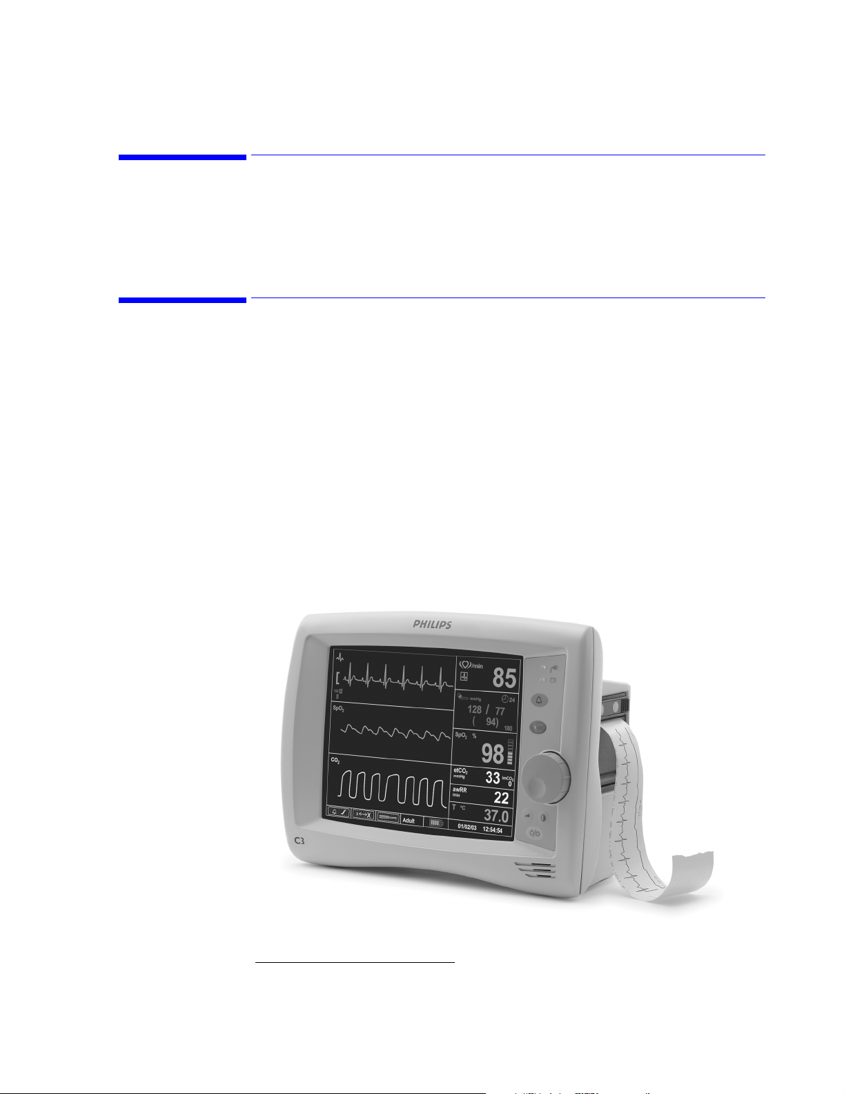
This manual contains information for servicing the C3 patient monitor, subsequently referred
to as "the monitor" throughout this manual. Only qualified service personnel should service
this product. Before servicing the monitor, carefully read the C3 Instructions for Use guide
for a thorough understanding of operation.
C3 Patient Monitor Description
The purpose and function of the C3 family of patient monitors is to monitor ECG, heart rate,
non-invasive blood pressure (NBP), functional arterial oxygen saturation (SpO
rate, temperature and carbon dioxide
and hospital-type facilities, such as clinics.The monitors may be used by clinical users during
hospital transport.
The intended users of the C3 patient monitors are clinicians and nursing staffs within hospital,
out-patient, and ambulatory settings. This monitor is not intended for helicopter transport or
home use.
Introduction
), respiration
1
(CO2) for adult and pediatric patients in hospital areas
2
The physical and operational characteristics of the monitor are described in the C3
Instructions for Use guide.
1. Carbon Dioxide monitoring is available within the C3 Sedation monitors only.
Overview
1-3
Page 24

Features and Options
Features and Options
The measurement parameters and features for each model are indicated below.
Front Panel Description
Order
Number
Description Display Measurements Printout
Color ECG NBP Temp SpO2CO2Recorder
862474 Standard Color ••••• (optional)
862478 Sedation Color ••••••(optional)
The following diagram illustrates the controls located on the front panel of your C3.
A
B
C
D
1-4 Overview
E
Callout Button/LED
A. AC LED
B. Battery LED
C. Audio Alarm Control button
D. NBP button
E. Volume button
F. Contrast button
G. On/Standby button
F
G
Page 25
Features and Options
Front of Monitor
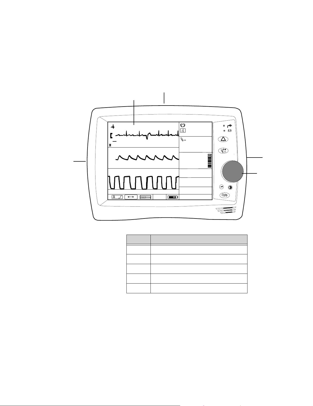
Use the following diagram to familiarize yourself with the main features of your C3 monitor.
The recorder module and all patient input connectors are located on the monitor’s side panels.
C
B
/min
85
mV
1.0
cm
SpO
2
A
CO
2
x
X
Adult
mmHg
183/ 107
(149 )
SpO
%
2
93
etCO
2
mmHg
33
awRR
/min
23
°
T °C
37.8
01/06/03 01:09:17
180
imCO
1
D
2
E
Callout Description
A. Patient Monitoring Input Connectors
B. Main Monitoring Screen
C. Handle
D. Recorder (optional. Not available in all models)
E. Navigation Wheel
Overview
1-5
Page 26
Features and Options
Rear of Monitor
100-230V~
50-60 Hz. 1.0A
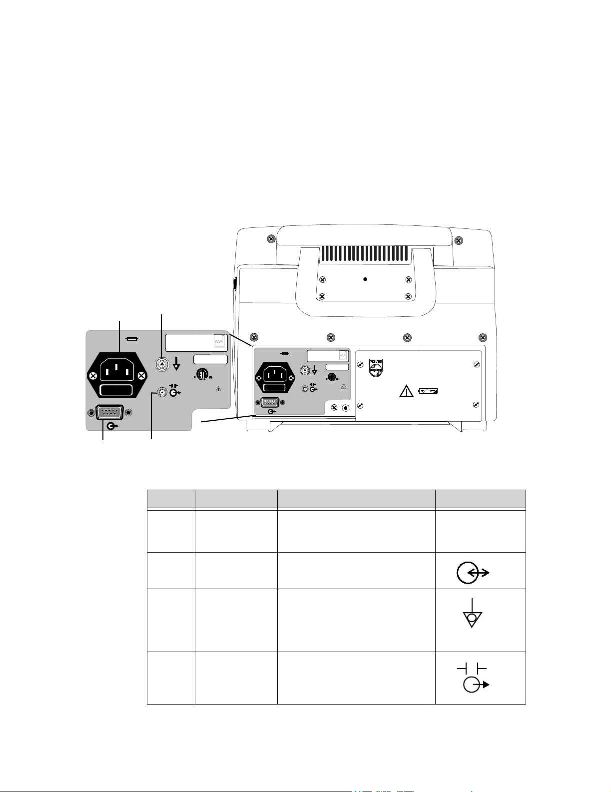
The following diagram is of the rear panel. For an explanation of the symbols located on this
panel, see “Explanation of Symbols” on page vi.
The C3 has four connections on its rear panel. The diagram below is of the rear panel. It
shows you how to make the four possible connections (Defib Sync, Equipotential, AC Input,
and RS-232 I/O).
A
T1AL 250VT1AL 250V
C
9700859
IPX1
YYYY-XX
CE
0123
100-230V~
50-60 Hz. 1.0A
T1AL 250VT1AL 250V
970085
YYYY-XX
CE
0123
IPX1
PHILIPS C3 PATIENT MONITOR
Manufactured for Philips for
Philips Medical Systems
3000 Minuteman Road
Andover, MA 01810
Made in U.S.A.
B
D
Callout Connector Connector Type Label
A. AC Input 3-line connector IEC 320 receptacle
100 - 240V ~
50 - 60Hz
1A
B. RS-232 I/O DB-9 (male)
C. Equipotential
Equipotential
Grounding Post
The equipotential grounding post
may be used by facilities as required
by their procedures.
D. Defib Sync 2.5mm subminiature phone jack
1-6 Overview
Page 27
Features and Options
Screen Display
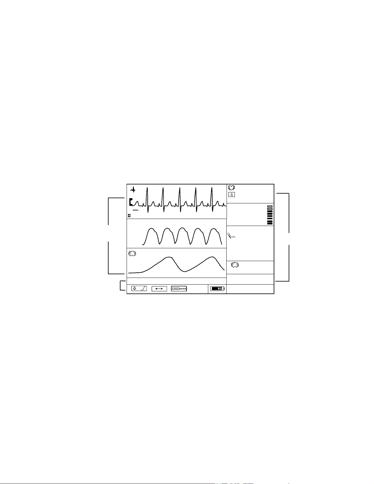
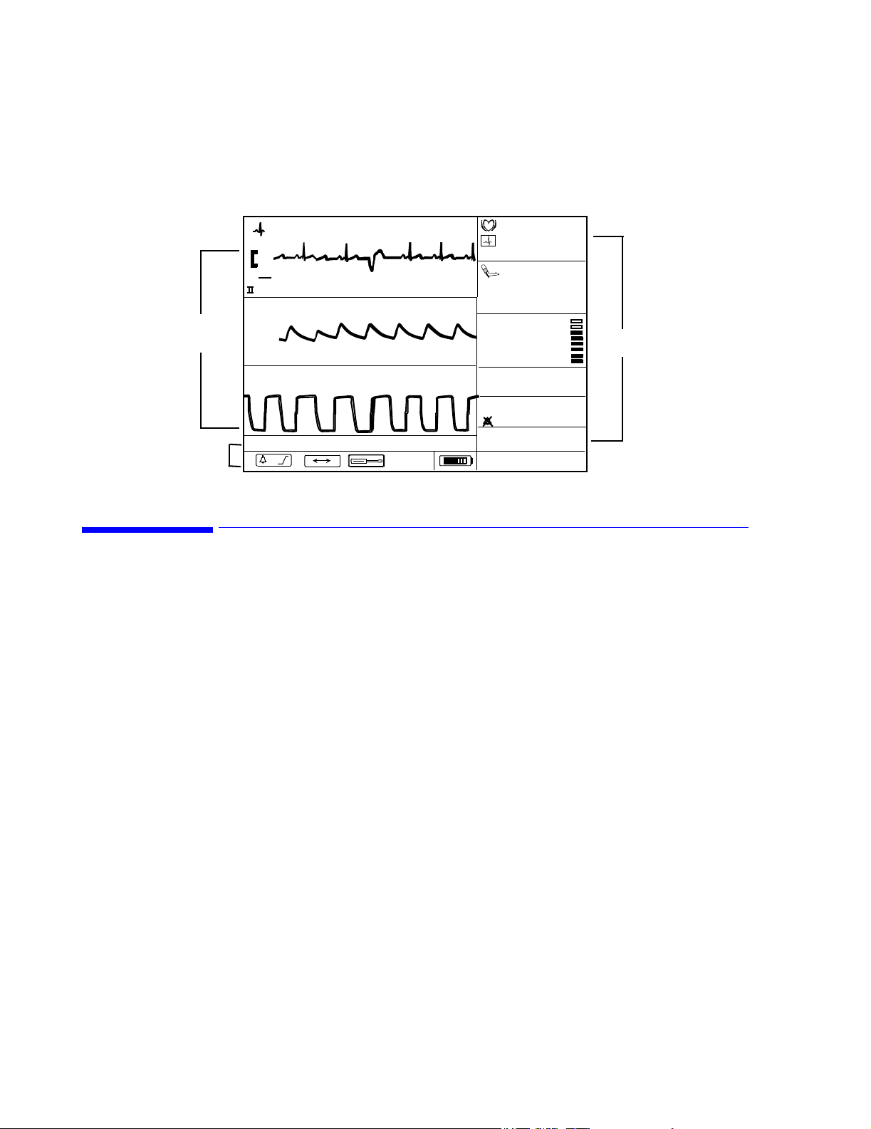
The LCD displays parameter values, real-time waveforms, alarm messages and screen
selection icons.
• Numeric frames displays icons and numeric values of
real-time physiologic parameter.
• Waveform frames displays real-time waveforms, graphical
trend, or tabular trend data.
• Message and Icon frames displays alarm messages and screen
selection icons.
Standard Model
/min
85
%
SpO
2
93
mmHg
183 / 107
(149 )
/min
14
Numeric
Frames
180
Waveform
Frames
1.0
SpO
mV
cm
2
Message
and Icon
Frames
T °C
37.8
x
X
Adult
01/06/03 01:09:17
Overview
1-7
Page 28
Additional Documentation
Frames
Message
and Icon
Frames
1.0
SpO
CO
mV
Sedation Model
/min
85
cm
2
2
x
X
Adult
mmHg
183/107
SpO
(149 )
%
2
180
93
etCO
2
mmHg
33
awRR
/min
T °C
01/06/03 01:09:17
23
37.8
imCO
1
Numeric
Frames
2
Additional Documentation
To perform test and troubleshooting procedures and to understand the principles of operation
and circuit analysis sections of this manual, you must know how to operate the monitor. Refer
to the C3 Instructions For Use guide to understand the various sensors, ECG leads, blood
pressure cuffs, CO
monitor. Instructions for cleaning and caring for the accessories can also be found in the
individual Directions for Use that accompany these accessories.
2
parameters and accessories and temperature probes that work with the
1-8 Overview
Page 29

Site Preparations
This chapter describes how to perform site preparation and how to comply with safety
guidelines and requirements.
2
Site Preparations 2-1
Page 30

General Site Preparation Safety Information
General Site Preparation Safety Information
WarningWarning
To avoid contaminating or infecting personnel, the service environment or other
equipment, make sure that equipment which has been used before has
been appropriately disinfected and decontaminated.
Disconnect the monitor from the AC source by unplugging the power cable from the AC
power connector located on the rear of the monitor. The On/Standby
button does not disconnect the monitor from the AC mains supply
Accessory equipment connected to the monitor’s data interface must be certified
according to IEC Standard 60950 for data-processing equipment or
IEC Standard 60601-1 for electromedical equipment. All combinations
of equipment must be in compliance with IEC Standard 60601-1-1
systems requirements.
Explosion Hazard. Equipment not suitable for use in the presence of a flammable
anaesthetic mixture with air, or with oxygen or nitrous oxide.
Make sure that you have read all applicable instructions before attempting to install the
wall mount.
Wall mounts that are intended to support monitors must be capable of supporting 4
times the weight of the monitor when properly installed.
Do not mount any portion of a monitoring instrument over a patient’s bed.
Do not exceed the maximum rated load specified for each wall mount.
Ensure that no electrical wiring, utilities, or piping interfere with the selected wall
mounting location.
Note
Do not return sensors, patient cables, NBP tubing and cuff, or the power cord.
2-2 Site Preparations
Page 31

Site Preparation Guidelines
• Check that the environment is reasonably free from dust, vibration, corrosive or
explosive gases and is within specified temperature and humidity ranges. See
Chapter 12, “Specifications”
• Position the monitor so that the display is clearly visible and the controls are easy to
reach.
Warning, Cautions and Safety Precautions
Site Preparation Guidelines
Patient Safety
Patient Leakage Current
To better secure patient safety, become familiar with the details in
Chapter 12, “Specifications.”
The patient leakage current is <= 50µA @ 250 V. The monitor has patient input connectors
(Type CF) that are protected against the effects of defibrillation and electrosurgery.
You will find the following heart symbol on the side of the monitor where the patient
monitoring input connectors are located. The symbol indicates that the monitor is Type CF
and is designed to have special protection against electric shocks (particularly regarding
allowable leakage currents, having a F-Type applied part, according to the standards IEC
60601-1/EN60601-1/CSAC22.2 601.1/UL 2601-1), and is defibrillator proof.
Site Preparations
2-3
Page 32

Preparing to Use the Monitor
Preparing to Use the Monitor
WarningWarning
To avoid contaminating or infecting personnel, the service environment or other
equipment, make sure that equipment which has been used before has
been appropriately disinfected and decontaminated.
Power
Source
Requirements
Protecting Against Electrical Shock
Equipotential
Grounding
See the section titled, “Electrical” on page 12- 3 for all electrical specifications.
The C3 patient monitor is classified as Class I Equipment with an internal power source
according to IEC 60601-1/CSAC22.2 601.1/UL 2601-1, which means that it is a monitor
included in the protective grounding (protective earth) system of the room by way of
grounding contacts in the power plug.
WarningWarning
Disconnect the monitor from the AC source by unplugging the power cable from the AC
power connector located on the rear of the monitor. The On/Standby
button does not disconnect the monitor from the AC mains supply.
To eliminate potential differences between difference pieces of equipment, the monitor must
have a separate connection to the equipotential grounding system.
One end of the equipotential grounding cable (potential equalization conductor) is connected
to the equipotential grounding post on the rear of the monitor, and the other end is connected
to one point of the equipotential grounding system.
Combining Equipment
2-4 Site Preparations
All combinations of medical equipment with non-medical equipment must comply with IEC
60601-1-1.
WarningWarning
Accessory equipment connected to the monitor’s data interface must be certified
according to IEC Standard 60950 for data-processing equipment or
IEC Standard 60601-1 for electromedical equipment. All combinations
of equipment must be in compliance with IEC Standard 60601-1-1
systems requirements.
Page 33

Unpacking the Monitor
Disposing of the Monitor
To avoid contaminating or infecting personnel, the environment or other equipment, make
sure you disinfect and decontaminate the monitor appropriately before disposing of it in
accordance with your country’s law for equipment containing electrical and electronic parts.
For disposal of parts and accessories, such as ECG and SpO
follow local regulations regarding disposal of hospital waste.
For disposal of the lead-acid battery, follow local regulations for safe disposal of lead.
WarningWarning
Explosion Hazard. Equipment not suitable for use in the presence of a flammable
Unpacking the Monitor
The box comes with the following:
• the C3 Instructions for Use guide
• the C3 patient monitor
• an AC power cord
In addition, you should receive all of the accessories and options that you have ordered.
, where not otherwise specified,
2
anaesthetic mixture with air, or with oxygen or nitrous oxide.
If there is anything missing, contact your Philips Medical Systems representative
immediately.
Checking the Shipment
Examine the carton carefully for evidence of damage in transit. If you discover any damage,
contact the carrier immediately. Retain all packing material.
If you have to return the monitor, contact the Philips Response Center or your local Philips
representative for shipping instructions.
To pack the monitor for return, disconnect all cables. Pack the monitor in its original shipping
carton. If this is unavailable, use a suitable carton with appropriate packing material to protect
the monitor during shipping.
Note
Do not return sensors, patient cables, NBP tubing and cuff, or the power cord.
Site Preparations
2-5
Page 34

Returning System Components
Returning System Components
If it is necessary to return the monitor for service, call the Philips Response Center or your
local Philips representative for shipping instructions. Have all equipment serial numbers
available when calling.
To pack the monitor for return, disconnect all cables. It is not necessary to return sensors,
patient cables, NBP tubing and cuff or power cord. Pack the monitor to be returned in its
original shipping carton if available. If not, use a suitable carton with appropriate packing
material to protect the monitor during shipping.
2-6 Site Preparations
Page 35
Mounting
Mounting
WarningWarning
Make sure that you have read all applicable instructions before attempting to install the
wall mount.
Wall mounts that are intended to support monitors must be capable of supporting 4
times the weight of the monitor when properly installed.
Do not mount any portion of a monitoring instrument over a patient’s bed.
Do not exceed the maximum rated load specified for each wall mount.
Ensure that no electrical wiring, utilities, or piping interfere with the selected wall
mounting location.
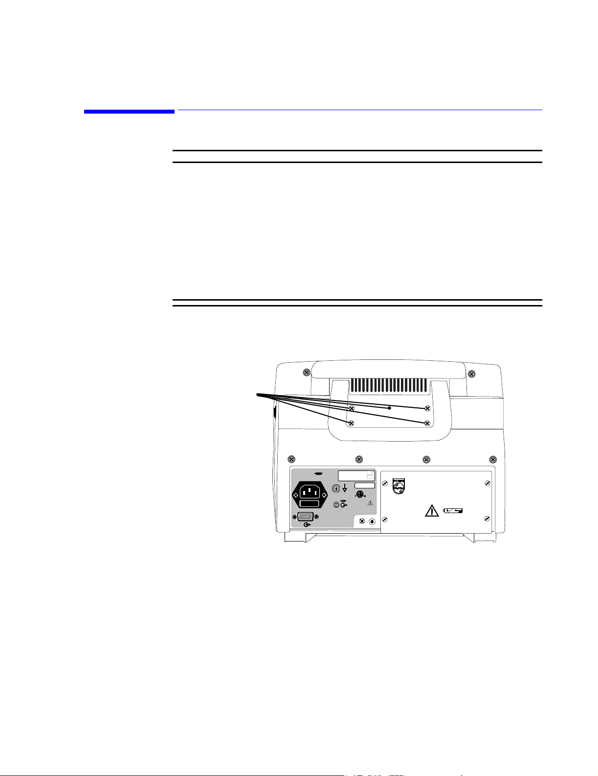
The rear panel includes threaded standoffs for attaching a mounting system accessory.
Mounting
Standoffs
100-230V~
50-60 Hz.
T1AL 250VT1AL 250V
97008
YYYY-XX
CE
0123
IPX1
PHILIPS C3 PATIENT MONITOR
Manufactured for Philips for
Philips Medical Systems
3000 Minuteman Road
Andover, MA 01810
Site Preparations
2-7
Page 36

Warnings, Cautions, and Safety Precautions Relating to Wall Mount Installation
Warnings, Cautions, and Safety Precautions Relating to Wall Mount
Installation
• Make sure that you have read all applicable instructions before attempting to install the
wall mount.
• Wall mounts that are intended to support monitors must be capable of supporting four
times the weight of the monitor when properly installed.
• If wall mounts are to be installed on plaster board walls, we recommend that the mounts
be installed using steel or plywood plates sufficient to distribute the load over a large
section of the wall. Lead expansion bolts are neither adequate nor safe for this
purpose.
• It is the responsibility of the hospital, institution, or its designated representatives to
determine that the wall is adequate to safely mount monitoring instrumentation. This
includes the selection of and proper installation of the appropriate fasteners and mounts.
In a new construction, or in a remodelled construction where the wall can be completely
or partially removed, a 16-gauge steel stud should be mounted for the purpose of
attaching the wall channel. This design safety factor is based on four times (4x) the
maximum rated load.
• GCX Wall Channel: Always reposition the adjustable channel safety stop under the
adapter plate when the height of the monitor is changed.
• The channel safety stop prevents the mounting device from inadvertently falling or
being pulled out of the wall channel. Do not remove this stop while the mount is
supporting a monitor.
• Do not mount any portion of the monitor over a patient’s bed.
• Do not exceed the maximum rated load specified for each wall mount.
• Ensure that no electrical wiring, utilities, or piping interface with the selected wall
mounting location.
• Do not install wall channel onto solid brick or brick veneer walls. Do not attempt to
install wall mounts onto crumbly wall material.
• Check the mounting hardware holding the wall channel or bracket to the wall every 12
months. Tighten if necessary.
2-8 Site Preparations
Page 37
Mounting the GCX Wall Channel
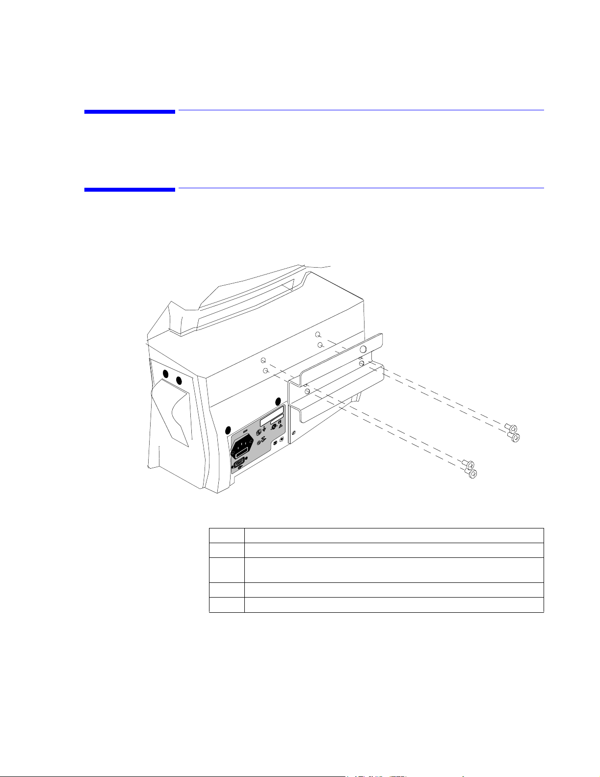
To install the GCX Wall Channel and Tilt/Swivel mount, follow the documentation packaged
with the channel.
Attaching the Mounting Plate to the Monitor
Mounting the GCX Wall Channel
Step Action
1 Unpack the mounting plate and check all parts are present.
2 Unscrew the 5 screws from the mounting standoffs located on the rear of the
monitor.
3 Place the Wall Plate over the mounting standoffs.
4 Re-insert and tighten the screws to secure the wallplate to the monitor.
Site Preparations
2-9
Page 38
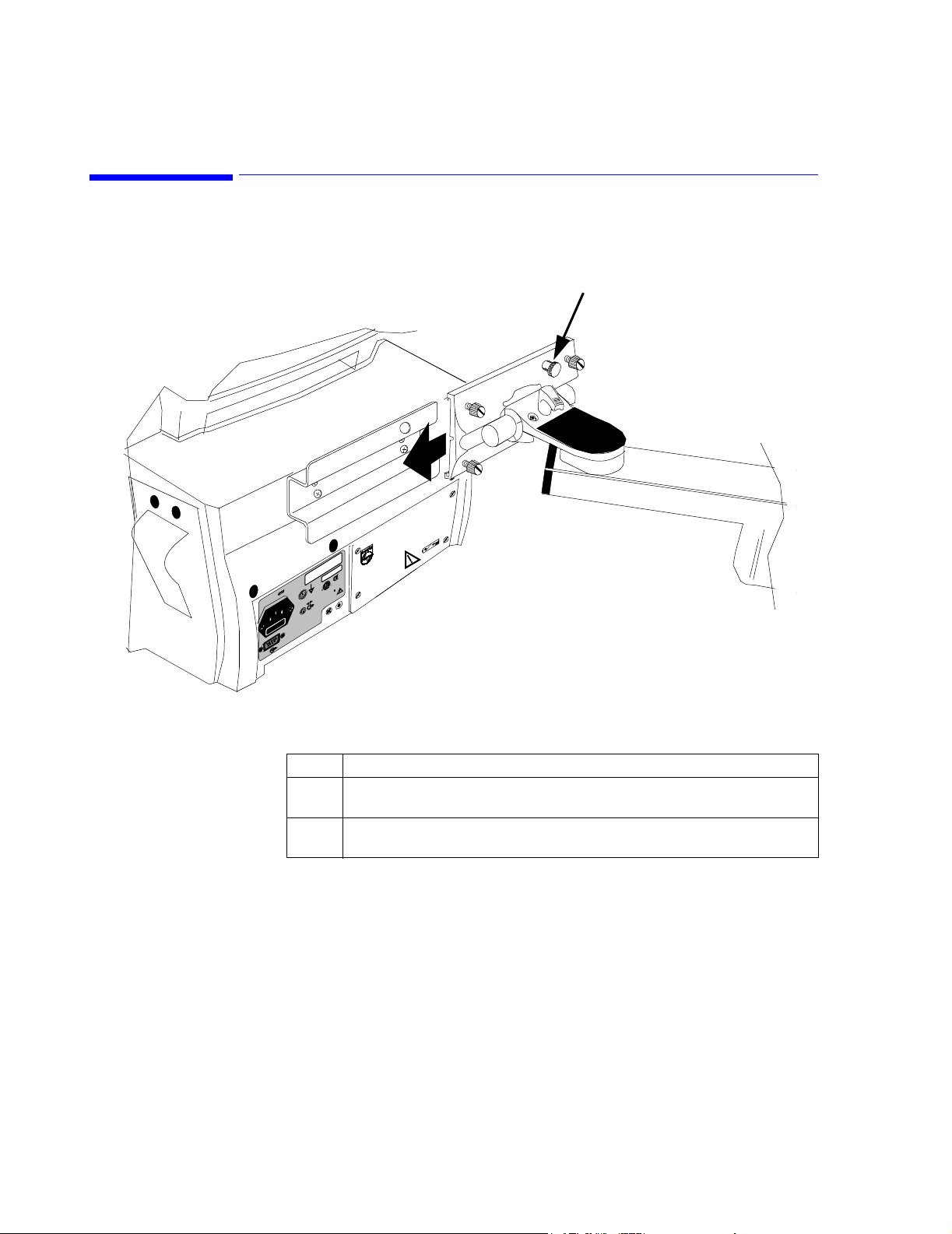
Attaching the Monitor to the Wall Channel
Attaching the Monitor to the Wall Channel
r
o
t
r
i
o
n
f
o
s
M
p
i
t
l
i
n
h
s
e
i
P
t
m
r
a
e
t
o
P
f
s
3
y
d
d
S
a
C
e
l
r
o
s
a
u
R
t
p
c
i
i
l
c
n
i
d
a
0
a
f
h
e
1
u
P
m
8
M
n
e
1
t
a
s
0
u
p
M
i
n
l
A
i
i
.
M
h
M
,
A
P
.
r
0
e
0
S
.
v
0
U
o
3
d
n
i
n
e
A
d
a
M
Latch
3
2
1
0
9
5
8
0
0
7
9
1
X
P
I
Step Action
1 Slide the Tilt/Swivel mount into the Wall Plate as illustrated by the above
diagram.
2 Make sure the latch snaps into the hole on the upper right-hand corner of the
wallplate.
2-10 Site Preparations
Page 39

Maintaining the Monitor
This chapter describes how to clean your monitor and how to keep your monitor in the best
working condition.
3
Maintaining the Monitor 3-1
Page 40

Maintenance Safety Information
Maintenance Safety Information
WarningWarning
Follow local governing ordinances and recycling plans regarding disposal or recycling
batteries and other device components.
If the battery shows signs of damage or signs of leakage, replace it immediately. Do not
use a faulty battery in the monitor.
Never use a monitor that is monitoring a patient to perform battery conditioning.
Caution
Do not immerse the monitor in liquid or use caustic or abrasive cleaners.
Do not spray or pour any liquid on the monitor or its accessories.
Do not allow any liquid to penetrate connectors or openings in the monitor’s chassis.
3-2 Maintaining the Monitor
Page 41

Objectives
Concepts
Objectives
In order to meet this chapter’s objectives, you should be able to perform light maintenance
and preventative maintenance for the monitor through the following tasks:
• Inspection of the monitor
• Cleaning the monitor
• Battery Maintenance
Light
Maintenance
Battery
Conditioning
Light maintenance tasks can be defined as those tasks required to maintain the monitor in
clean, functional working order. These include inspection, cleaning practice and battery
maintenance as well as the continuous observation of replaceable parts for wear.
A rechargeable battery must be conditioned at regular intervals to prepare it for further
charge/discharge cycles. Conditioning a battery refers to the complete discharge of a charged
battery by allowing it to die out while in non-critical use. The empty battery may then be
recharged and put back into use.
Maintaining the Monitor
3-3
Page 42

Recommendations for Maintenance Frequency
Recommendations for Maintenance Frequency
The following table is the recommended maintenance schedule for your C3 monitor. The
maintenance checklist appears in the next section of this chapter. The checklist may be
photocopied and should be completed by the maintainer. It should be filed for future
reference. The owner of the equipment is responsible for the performance of the maintenance
activities with the schedule below.
Maintenance Frequency Procedure
Inspect the monitor, cables
and cords
Cleaning As needed “Cleaning”on page 3-7
Safety checks according to
IEC 60601-1
Functional testing
procedures
Performance Assurance At least once every year, or
Replace backlight 20,000 hours (about 4
NBP Maintenance Every year, or as needed, if
Battery Maintenance Every two years “Battery Maintenance”on page 3-7
Battery Conditioning Approximately every 200
Daily “Inspecting the Monitor”on page 3-6
At least once every 2 years,
after any repairs, if the
monitor has been dropped
or as needed.
When functional defects in
the measurements are
suspected.
as needed (if you suspect
defects in the
measurements).
years) of continuous use, or
as needed.
the monitor has been
opened, or you suspect
defects in the measurement.
deep discharges.
and “Inspecting the Cables and
Cords”on page 3-6
“Patient Safety Tests”on page 4-39
“Functionality Assurance”on page 4-3
“Performance Assurance Test”on page
4-11
“Replacing the Backlight Tube”on
page 7-9
“Preventative Maintenance Tests”on
page 4-14
“Conditioning a Battery”on page 3-10
3-4 Maintaining the Monitor
Page 43

Maintenance Checklist
Maintenance Checklist
Topics See Page....
Inspect Cables, Cords and Housing 3-6
Replacing the Backlight Tube
Assembly
NBP Preventative Maintenance 4-14
Cleaning Guidelines 3-7
Checking the Battery Status 3-8
Charging the Battery 3-9
Conditioning the Battery 3-10
Testing the Monitor 4-1
7-9
Check Here if
Completed
Date
Completed
Maintaining the Monitor
3-5
Page 44

Inspecting the Monitor
Inspecting the Monitor
If you discover a problem while inspecting monitor, contact your biomedical department or
Philips Medical Systems.
With the monitor turned Off:
Step Action
Examine the exterior of the monitor for cleanliness and general physical
1
condition. Verify that the housing is not cracked or broken, that
everything is present, that there are no spilled liquids and that there are
no signs of abuse.
2 Inspect all accessories (cables and sensors) external to the monitor,
referring to the accessories’ documentation.
3 Switch the monitor On and verify that the backlight is bright enough.
Check that screen is at its full brightness. If the brightness is not
adequate, contact your biomedical department. Philips Medical Systems
recommends replacing the backlight about every 4 years.
4 If you are operating the monitor from battery, verify that the battery is
adequately charged before you begin use.
Inspecting the Cables and Cords
If you discover a problem while inspecting the cables and cords, replace the cable, or contact
your biomedical department.
Step Action
Examine the power plug and cord for damage. Make sure that the prongs
1
of the plug do not move in the casing. If damaged, replace the entire cord
with the appropriate Philips power cord.
2 Inspect the patient cables and leads and their strain reliefs for general
condition. Make sure there are no breaks in the insulation. Make sure
that the connectors are properly engaged at each end to prevent rotation
or other strain.
3 With the sensor or electrodes applied to the patient, and the monitor
turned On, flex the patient cables near each end to make sure that there
are no intermittent faults.
3-6 Maintaining the Monitor
Page 45

Cleaning
Cleaning
Caution
Do not immerse the monitor in liquid or use caustic or abrasive cleaners.
Do not spray or pour any liquid on the monitor or its accessories.
Do not allow any liquid to penetrate connectors or openings in the monitor’s chassis.
To clean the monitor, dampen a cloth with a commercial, nonabrasive cleaner and wipe the
top, bottom, and front surfaces lightly. For cables, sensors and cuffs, follow the cleaning
instructions in the Directions for Use shipped with those components.
If liquid is accidentally spilled on the monitor, clean and dry it thoroughly before reuse.
If in doubt about monitor safety, refer the unit to qualified service personnel.
Battery Maintenance
This section provides some information on how to handle and maintain the battery.
WarningWarning
Follow local governing ordinances and recycling plans regarding disposal or recycling
About the Battery
Storing the monitor for a long period of time without charging the battery can degrade the
battery capacity. A complete battery recharge (>90%) requires 8 hours in standby mode or 14
hours in operational mode. If the battery needs charging, connect the monitor to the AC outlet
as described “Charging the Battery”on page 3-9
If the monitor operates for less than one hour on battery power before the low battery alarm
occurs, the battery should be conditioned. See “Electrical”on page 12-3 for typical battery
operating times and conditions.
If the same symptom persists after the battery is conditioned and indicating a full charge, the
battery should be replaced (see “Removing the Battery”on page 7-4 for more information).
batteries and other device components.
Maintaining the Monitor
3-7
Page 46

Battery Maintenance
Battery Guidelines
Checking the Battery Status
To get the most out of the battery, observe the following guidelines:
• The shelf-life of a fully charged battery is about 6 months.
• After a battery has been activated, keep it charged. If it is not in use, recharge it every 3
to 4 months.
• Condition the battery approximately every 200 deep discharges.
• Remove the battery from the monitor if it is not being used regularly. (Leaving the
battery in a monitor that is not in regular use using the battery will shorten the life of
the battery).
• Battery Disposal - We recommend replacing the monitor’s sealed, lead-acid battery at 2
year intervals. Follow local governing ordinances and recycling plans regarding
disposal or recycling of batteries and other device components.
• Do not dispose of the battery in normal waste containers.
WarningWarning
If the battery shows signs of damage or signs of leakage, replace it immediately. Do not
use a faulty battery in the monitor.
When the monitor is connected to the AC (mains) power supply, the battery charges
automatically.
Battery status is indicated several ways:
• LEDs on the front panel of the monitor.
• Battery gauge on the monitor’s main monitoring screen.
• INOP messages
The AC LED is only on when the power cord is connected and the AC power is available to
the monitor. In this case, the battery can be either charging or fully charged.
3-8 Maintaining the Monitor
Page 47
Battery Maintenance
Identifying Battery Strength
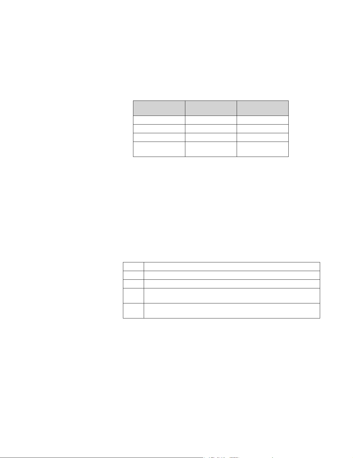
You can determine the monitor’s battery strength by the color of the battery icon, or by the
number of illuminated bars on the battery icon. The following table describes the battery icon
behavior:
Number of Bars
Illuminated
3, 4, or 5 Green Constant display
2 Yellow Constant display
1 Red Constant display
0 Red Battery icon flashes
Color Used Behavior
and message displays
• If the battery operating time is less than 30 minutes, the battery icon flashes. A low
priority audio alarm sounds (1 beep every 4 seconds).
• When the battery is empty, a "Low Battery" INOP message displays in the Message
frame and the audible alarm sounds. Pressing any front panel button clears the INOP
and silences the audible alarm. The battery icon continues to flash until the monitor is
powered down or automatically switches off.
If the new battery is partly or fully charged, the monitor starts operating.
Charging the Battery
A complete battery recharge (>90%) requires 8 hours in standby mode or 14 hours in
operational mode.
To charge the battery:
Step Action
1 Connect the monitor to the AC power source using the proper power cord.
2 Verify that the AC Input Indicator LED is lit.
3 Charge the battery for at least 8 hours. The battery may require a full discharge/
charge cycle to restore it to its normal capacity.
4 To check for a full charge, perform the procedure described in “Battery
Performance Test”on page 4-22.
Maintaining the Monitor
3-9
Page 48

Battery Maintenance
Conditioning
a Battery
Why is Battery
Conditioning
Necessary?
When Should
Battery
Conditioning
be Performed?
How to
Condition a
Battery
Battery conditioning re-calibrates the battery to ensure that it has accurate information on the
actual battery capacity.
WarningWarning
Never use a monitor that is monitoring a patient to perform battery conditioning.
The capacity of a battery decreases gradually over the lifetime of the battery. Each time a
battery is charged its capacity decreases slightly. Therefore, the operating time of a monitor
running off the battery also decreases with each charge cycle.
Battery conditioning ensures that the value storied in the battery for its fully capacity takes
account of this decrease, so that the remaining battery charge can be calculated accurately,
and the low battery warning given at the right time.
Battery conditioning should be performed:
• Every 200 deep discharge cycles.
We recommend two full charge and discharge cycles to ensure proper conditioning,
independent of the initial condition of the battery.
If you need to continue battery powered monitoring, replace the battery in the monitor with a
different charged and conditioned battery. You cannot condition a battery in a monitor that is
being used.
3-10 Maintaining the Monitor
Step Action
1 Insert the battery that is to be conditioned into a monitor that is not currently
being used.
2 Disconnect the monitor from the AC power supply.
3 Turn on the monitor, and leave it on until it switches off automatically.
4 Turn the monitor Off using the On/Standby button located on the front panel.
5 Reconnect the monitor the AC power supply.
6 Charge the battery until it is full. (When you turn the monitor On, the 5 bars in
the battery gauge on the main monitoring screen will be illuminated).
7 Repeat steps 2 to 6.
Page 49

Battery Maintenance
Battery INOP Messages
The following battery-related INOP messages are issued by the monitor. All Battery INOPs
continue until the monitor is plugged into the AC power or the INOP condition is fixed.
• "Low Battery" - This is an INOP which indicates that the remaining battery-operating
time is less than approximately 30 minutes.
Maintaining the Monitor
3-11
Page 50

Battery Maintenance
3-12 Maintaining the Monitor
Page 51

Testing the Monitor
This chapter provides a checklist of testing procedures used to verify performance following
repairs or during routine maintenance. All tests can be performed without removing the
monitor’s covers.
If the monitor fails to perform as specified in any test, repairs must be done to correct the
problem before the monitor is returned to the user.
4
Testing the Monitor 4-1
Page 52

Testing Safety Information
Testing Safety Information
WarningWarning
Perform all leakage tests any time the unit is opened.
AC mains voltage is present on the applied part terminals during this test. Exercise
caution to avoid electrical shock hazard.
Note
The monitor must be placed in Diagnostic Mode, with the NBP test screen active for each of
the NBP tests.
If the test fails, ensure the integrity of the cuff and tubing, then test again. If the test fails
again, verify the integrity of all the pneumatic tubing inside the monitor.
Before beginning the Battery Performance test, ensure that the monitor is disconnected from
the AC power source.
4-2 Testing the Monitor
Page 53

Objectives
Concepts
Objectives
In order to meet this chapter’s objectives, you should be able to test the monitor through the
following types of tests:
• Performance Assurance Check List
• Accuracy, Calibration and Performance Procedures
• Patient Safety Checks
For inspection procedures; preventative maintenance procedures; cleaning procedures; and
battery maintenance, refer to this chapter and Chapter 2, “Site Preparations”.
Functionality
Assurance
Preventative
Maintenance
Performance
and Safety
Tests
This refers to the combined Performance Assurance Test and Functionality Testing
Procedures found in this chapter. These tests verify correct monitor functionality in general
terms.
Preventative Maintenance refers specifically to the service calibration tests required to ensure
the monitor measurement results are accurate. When authorized Philips personnel service the
monitor, they report these results back to Philips. The collected data forms a database to be
used in product development. These specific tests are required for the NBP parameter. It is not
necessary for hospital personnel to report results.
This concept refers to all the remaining accuracy and performance tests available on the
monitor, including safety tests and checks for the monitor.
Testing the Monitor
4-3
Page 54

Testing Checklist
Testing Checklist
The tests described in this chapter are listed in the table below. Use this table
as a checklist.
Topics See...
Functionality Assurance Tests
Performance Assurance Test page 4-11
Power-On Self-Test page 4-11
Alarm Test page 4-12
Volume Control Test page 4-12
Preventive Maintenance Tests
NBP page 4-14
Performance Procedures
Battery Performance Test page 4-22
Temperature Test page 4-23
ECG Performance page 4-25
Respiration Performance page 4-25
SpO
Performance page 4-27
2
CO2 Performance page 4-29
Serial Interface and Nurse Call Signal Test page 4-36
ECG Sync Performance Test page 4-38
Patient Safety Tests
S(1) Ground Integrity page 4-39
S(2) Electrical Leakage page 4-41
S(3) Earth Leakage Current page 4-41
S(4) Enclosure Leakage Current page 4-42
S(5) Patient Leakage Current page 4-43
S(6) Patient Leakage Current with Mains page 4-44
Check Here
if Completed
Date
Completed
4-4 Testing the Monitor
Page 55

Test Reporting
Test Reporting
The following table shows what must be recorded on the Service Record after completing the
tests in this chapter.
Test What to Record
Functionality Assurance Tests
Visual V:P or V:F
Power On PO:P or PO:F
Preventive Maintenance Tests
P NBP
Performance Procedures
Performance PCO2: P/X1/X2/X3/X4/X5/X6/X7 or
CO
2
Patient Safety Tests
Safety(1) Ground Integrity S(1):P or S(1):F
Safety(2) Earth Leakage Current S(2):P or S(2):F
Safety(3) Enclosure Leakage Current S(3):P or S(3):F
Safety(4) Patient Leakage Current S(4):P or S(4):F
Safety(5) Patient Leakage Current with Mains S(5):P or S(5):F
PN:P/X1/X2/X3/X4/X5 or
PN:F/X1/X2/X3/X4/X5
See page 4-15 for details
PCO2: F/X1/X2/X3/X4/X5/X6/X7
See page 4-30 for details
Where P = Pass, F = Fail and X is the measured value as defined in the tests described in this
chapter.
Testing the Monitor
4-5
Page 56

Recommendations for Testing Frequency
Recommendations for Testing Frequency
The testing checklist appears in the next section of this chapter. Perform the procedure as
indicated in the suggested testing timetable. These timetable recommendations do not
supersede local requirements.
Suggested Testing Frequency
Functionality Assurance
• Performance Assurance Test
• System Self-Test
Preventative Maintenance Tests (NBP) Every year, or as needed.
Performance Tests
• Battery Performance
• Temperature Accuracy
• ECG Performance
• Resp Performance
•SpO
•CO2 Performance
Performance
2
When functional defects in the measurements are
suspected, after any repairs, if the monitor has been
dropped or opened.
The battery performance test must be performed every
two years, before monitor repairs, or whenever the
battery is suspected as being the source of the problems.
All other test must be performed at least once every
year, if the monitor has been opened, or if you suspect
defects in the measurements.
• Serial Interface and Nurse Call
Signal Test
• ECG Sync Performance
Safety Checks (in accordance with IEC
60601-1)
• Ground Integrity
• Electrical Leakage
• Earth Leakage Current
• Enclosure Leakage Current
• Patient Leakage Current
• Patient Leakage Current with Mains
Voltage on the Applied Part
a. Only when in use as part of hospital protocol safety checks.
a
At least once every 2 years, after any repairs, if the
monitor has been dropped or opened.
4-6 Testing the Monitor
Page 57

Test Map
Test Map
The Test Map shows which tests are required in which situations.
Service Event
(When performing...)
Test Block Required
(...complete these test)
Installation • Visual
• Power On
Monitor exchange • Visual
•Power On
Monitor opened • Power On
• Pneumatic Leakage Test
• All Safety tests
Battery replacement • Power On
• Battery Performance
• All Safety tests
Speaker replacement • Power On
• Pneumatic Leakage Test
• All Safety tests
Backlight tube replacement • Power On
• Pneumatic Leakage Test
• All Safety tests
NBP pump replacement • Power On
• Pneumatic Leakage Test
• All Safety tests
• Preventative Maintenance Tests
module replacement • Power On
SpO
2
• Pneumatic Leakage Test
• All Safety tests
•SpO
module replacement • Power On
CO
2
Tests
2
• Pneumatic Leakage Test
• All Safety tests
Tests
•CO
2
Power supply module replacement • Power On
• Pneumatic Leakage Test
• Safety Tests
Patient monitoring I/O module
replacement
•Power On
• Pneumatic Leakage Test
• All Safety tests
• All Performance tests
Communications module replacement • Power On
• Pneumatic Leakage Test
• All Safety tests
Testing the Monitor
4-7
Page 58

Equipment
Equipment
The following table lists the equipment required for performance verification.
Equipment Description
Digital multimeter (DMM) Fluke model 87 or equivalent
Defib Sync Cable and
Switchcraft 3.5 mm phone plug
SpO
adapter cable M1943A
2
SpO
reusable sensor, adult finger M1191A
2
ECG trunk cable M1540C (ICU, AAMI) or M1550C (ICU, IEC)
ECG electrodes Standard
ECG lead sets M1605A (AAMI) or M1615A (IEC)
NBP tubing M1599B
NBP reusable cuff, adult 40401C
Pulse oximeter tester Clinical Dynamics Corp - SmartSat simulator with
ECG simulator Dynatech Nevada medSim 300 or equivalent
NBP simulator Bio-Tek BP Pump 2 or equivalent
Temperature simulator MedSim 300 or equivalent
Respiration simulator MedSim 300 or equivalent
Safety analyzer Bio-Tek 601 Pro or equivalent
Stopwatch Manual or electronic
Screwdriver flathead and philips
Tweezers any model
Electronic flowmeter M1026-60144
Cal 1 gas (5% CO
Cal 2 gas (10% CO
) 15210-64010
2
) 15210-64020
2
Cal gas flow regulator M2267A
Cal tube 13907A
M4820A (see page 4-38 to use a substitute cable)
Switchcraft 750 or equivalent
Nellcor simulator cable
4-8 Testing the Monitor
Page 59
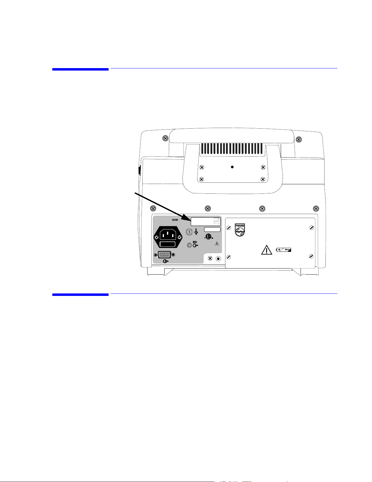
Serial Numbers
When recording test results, these are always associated with a particular monitor by means of
the serial number. The serial number is 10 characters and is located on the back of the
monitor.
Serial Numbers
Serial
Number
Passwords
100-230V~
50-60 Hz. 1.0A
T1AL 250VT1AL 250V
USC3xxxxxx
9700859
IPX1
YYYY-XX
CE
0123
PHILIPS C3 PATIENT MONITOR
Manufactured for Philips for
Philips Medical Systems
3000 Minuteman Road
Andover, MA 01810
Made in U.S.A.
Some of the test may require that you enter the Power-Up Default Menu located in the
Setup Menu. To access Power-Up Default Menu you must enter a password. The password
is:
2 - 1 - 5
Testing the Monitor
4-9
Page 60

Visual Test
Visual Test
Power On Test
Inspect the system for obvious signs of damage. Also check external leads and accessories.
What to record on the service record:
V:P or V:F
Step Action
1 Switch the monitor On.
2 Observe whether the system boots up successfully without displaying any error
codes. The main monitoring screen should display.
What to record on the service record:
PO:P or PO:F
.
4-10 Testing the Monitor
Page 61

Functionality Assurance Tests
The following assurance checks are recommended to verify proper operation daily before the
monitor is used to monitor a patient.
During functionality assurance checks, verify the overall operation by completing the
following Performance Assurance Tests.
Functionality Assurance Tests
Performance
Assurance
Test
Power-On Self-Test
To verify your monitor works properly, perform the following test:
Step Action
1 Using the supplied AC power cord, connect the monitor to the AC power source.
2 Verify that the AC LED is lit.
3 Do not connect any patient monitoring input connectors or cables to the monitor.
If there are any such connections, disconnect them.
4 If the monitor is Off, press the On/Standby button. The monitor must perform
the following sequence:
a. The screen backlight illuminates.
b. Three consecutively higher pitched "chimes" sound while the version
numbers of the boot and operational software display.
c. After successful completion, the main monitoring screen displays. No vital
sign numeric values or waveforms display.
5 If any error codes display, or the screen remains blank, refer to
Chapter 6, “Troubleshooting”.
After you first press the On/Standby button, the monitor displays a startup screen and
conducts a set of self-diagnostic test routines.
Testing the Monitor
4-11
Page 62

Functionality Assurance Tests
Alarm Test Tools Needed:
•SpO
adapter cable (M1943A)
2
• Clinical Dynamics Corp - SmartSat simulator (with Nellcor simulator cable)
Step Action
1 Connect SpO
the SpO
2 Set the simulator as follows:
3Press the On/Standby button to turn the monitor On.
4 After the normal power-up sequence, verify that the SpO
indicates zero, or is blank.
5 Verify that the following monitor reaction occurs:
a. After approximately 45 seconds, the monitor displays saturation and heart rate
as specified by the tester. Verify that the values are within the following
tolerances:
– Oxygen Saturation Range 79% to 83%
– Heart Rate Range 33 to 39 bpm
simulator cable to the SpO2 adapter cable. Connect the cable to
2
patient monitoring input connector.
2
Item Setting
Oximeter Nellcor
SpO2%
BPM 36
Pulse Mod 0.50%
81
% display initially
2
Volu me Control Test
b. The audible alarm sounds and both the SpO
flash, indicating both parameters have violated the default alarm limits.
c. The HR tone is heard. For this test, the HR tone source must be set to SpO2
from the Heart Rate Menu.
6Press the Alarm Silence button to temporarily silence the audible alarm.
7 Verify the following:
a. The audible alarm remains silenced.
b. The crossed-out bell icon displays in each numeric frame on the screen.
c. The SpO
d. The HR tone remains audible.
e. The audible alarm returns in approximately 120 seconds.
% and HR displays continue flashing.
2
% and Heart Rate (HR) displays
2
Tools Needed:
•SpO
adapter cable (M1943A)
2
• Clinical Dynamics Corp - SmartSat simulator (with Nellcor simulator cable)
4-12 Testing the Monitor
Page 63

Functionality Assurance Tests
Step Action
1 Connect SpO
simulator cable to the SpO2 adapter cable. Connect the cable to
2
the SpO2 patient monitoring input connector.
2 Set the simulator as follows:
Item Setting
Oximeter Nellcor
SpO2%
81
BPM 70
Pulse Mod 5.00%
3 a. Power the monitor On. Verify that the values are within the following
tolerances:
– Oxygen Saturation Range 79% to 83%
– Heart Rate Range 67 to 73 bpm
4Press the Alarm Silence button to temporarily silence the audible alarm.
5 Verify that the heart rate tone source, found in the Heart Rate Menu, is set to
.
SpO
2
6Press the Volume button on the monitor’s front panel. Within 3 seconds of
having pressed the button, rotate the navigation wheel clockwise to verify that
the beeping heart rate tone sound level increases.
7 Wait 3 seconds. Press the Volume button and rotate the wheel counter-clockwise
and verify that the beeping heart rate tone decreases until it is no longer audible.
Rotate the wheel clockwise to return the beep volume to a comfortable level.
After 3 seconds with no wheel activity, the volume adjust function terminates.
Testing the Monitor
4-13
Page 64

Preventative Maintenance Tests
Preventative Maintenance Tests
Preventative maintenance refers specifically to the service tests required to make sure the
monitor measurement results accurate. In cases where the performance of NBP is in question
or could have been configured during repair, the complete set of NBP tests described in this
service manual should be used.
The tests in this section verify the functionality of the monitor’s pneumatic system. All of
these tests, which the exception of the Basic Pneumatic Leakage (BPL) Test, require the use
of an NBP simulator.
Note
The monitor must be placed in Diagnostic Mode, with the NBP test screen active for each of
the NBP tests. To place your monitor into this mode see page 4-9.
Tools Needed for NBP Testing:
• NBP cuff (40401C)
• NBP tubing (M1599B)
• Bio-Tek BP Pump 2 simulator or equivalent, with an internal test volume of 310 ml.
4-14 Testing the Monitor
Page 65

Documenting
NBP Test
Results
Preventative Maintenance Tests
The following table lists the tests that should be documented and summarizes how to
document the NBP test results.
Test Expected Test Results
Pressure Transducer Accuracy Test X1 = difference between the pressure on
the monitor and on the simulator
Difference less than or equal to 5
mmHg (0.7 kPa)
Pneumatic Leakage Test X2 = difference between the pressure at
the start (P1) and after one minute (P2)
Difference less than or equal to 6
mmHg (0.8 kPa)
Inflation Rate Test X3 = number of seconds for the monitor
to inflate
Rate between 1 and 6 seconds
Over-Pressure Test X4 = peak value
Peak value between 270 and 330 mmHg
(36 kPa and 44 kPa)
Deflation Rate Test X5 = mmHg (kPa) per second to deflate
1.8 mmHg/s to 4.8 mmhg/s
What to record on
service record
PN:P/X1/X2/X3/X4/X5
or
PN:F/X1/X2/X3/X4/X5
P = passed, F = failed
Testing the Monitor
4-15
Page 66

Preventative Maintenance Tests
Pneumatic
System
Functionality
To Z e ro the
Simulator
The following tests must be performed to verify pneumatic system functionality. Perform
these tests in the following order:
1. Pressure Transducer Accuracy
2. Pneumatic Leakage
3. Inflation Rate
4. Over-Pressure
5. Deflation Rate
Note
The pneumatic system includes an over-pressure safety limit function and a safety period
time-out function. These safety functions may interfere with NBP tests described in this
section. In order to avoid activating these safety functions, do not pressurize the system
above 270 mmHg (36 kPa) and do not pressurize the system for time periods that exceed 150
seconds.
If the simulator does not display a "0" before starting a test, use the following procedure to
zero the simulator:
1. Disconnect the hose from the simulator.
2. Press Home.
3. Press SETUP.
4. Press MORE.
5. Press MORE again
6. Press ZERO PRESSURE.
7. Press ZERO.
8. Press Home to return to main menu.
9. Reconnect the hose.
Before beginning the above test sequence, perform the following three steps:
4-16 Testing the Monitor
Step Action
1 Turn the NBP simulator On.
2 Perform the following sequence:
a. Press the Home button.
b. Press the Pressure Tests button.
c. Press the Pressure Leak Test button.
d. Press the Setup button.
e. Press 2, 5, 0, then Enter.
f. Set the Cuff to Internal.
3 Connect the simulator tubing to the NBP patient monitoring input connector.
4 Place the monitor in Diagnostic Mode with the NBP test screen active.
Page 67

Preventative Maintenance Tests
Pressure
Transducer
Accuracy Test
This test verifies the pressure accuracy of the monitor’s pressure transducer.
Step Action
1 Confirm that the simulator displays "Leak Test" (see steps 1 and 2, in the
previous table).
2Press the Volume button to ensure that both valves are closed.
3 Perform an offset adjustment so that the simulator and monitor both display a
pressure of 0 mmHg or kPa by doing the following:
a. Press the Contrast button on the monitor’s front panel.
b. If needed, zero the simulator (see “To Zero the Simulator” on page 4-16).
4Press Start on the simulator.
5 Allow 15-20 seconds for the pressure to stabilize. The pressure displayed on the
monitor and on the simulator should be within 5 mmHg (0.7 kPa) of one another.
Document the difference between the simulator value and the monitor value
(X1).
6Press the Stop button on the simulator to stop the test.
7 Press and hold the Volume button until the monitor displays a pressure of 0
mmHg or kPa.
8 If no further NBP tests are to be conducted, turn the monitor Off. Normal
monitoring operation returns the next time the monitor is turned On.
Pneumatic
Leakage Test
This test verifies the integrity of the pneumatic system.
Step Action
1 Turn the simulator on.
2 Perform the following sequence:
a. Press the Home button.
b. Press the Pressure Tests button.
c. Press the Pressure Leak Test button.
d. Press the Setup button.
e. Press 3, 0, 0, then Enter.
f. Set the Cuff to Internal.
3 Confirm that the simulator test screen is active and displays "Leak Test".
4Press the Volume button to ensure that both valves are closed.
5 Perform an offset adjustment so that the simulator and monitor both display a
pressure of 0 mmHg or kPa by doing the following:
a. Press the Contrast button on the monitor’s front panel.
b. If needed, zero the simulator (see “To Zero the Simulator” on page 4-16).
6Press the NBP button on the monitor’s front panel to activate the pump. Hold the
button until the monitor displays a pressure of approximately 250 mmHg
(33.3 kPa).
7 Allow 15-20 seconds for the pressure to stabilize. Record the pressure displayed
on the monitor (P1).
Testing the Monitor
4-17
Page 68

Preventative Maintenance Tests
Step Action
8 Start a one minute timer. After one minute, record the pressure displayed again
(P2). The pressure should drop by no more than 6 mmHg (0.8 kPa) during the
one minute period. Calculate (P1 - P2) and document the leakage test value (X2).
9 Press and hold the Volume button until the monitor displays a pressure of 0
mmHg or kPa.
10 If no further NBP tests are to be conducted, turn the monitor Off. Normal
monitoring operation returns the next time the monitor is turned On.
Inflation Rate
Test
This test verifies the inflation rate of the monitor.
Step Action
1 Turn the simulator on.
2 Perform the following sequence:
a. Press the Home button.
b. Press the Pressure Tests button.
c. Press the Pressure Leak Test button.
d. Press the Setup button.
e. Press 3, 0, 0, then Enter.
f. Set the Cuff to Internal.
3Press the Volume button to ensure that both valves are closed.
4 Perform an offset adjustment so that the simulator and monitor both display a
pressure of 0 mmHg or kPa by doing the following:
a. Press the Contrast button on the monitor’s front panel.
b. If needed, zero the simulator (see “To Zero the Simulator” on page 4-16).
5Press the NBP button on the monitor’s front panel to activate the pump, and
simultaneously start the timer. Hold the button until the monitor displays a
pressure of 250 mmHg (33.3 kPa), then stop the timer. The inflation rate should
be between 1 and 6 seconds. Document the number of seconds (X3).
6 Press and hold the Volume button until the monitor displays a pressure of 0
mmHg or kPa.
7 If no further NBP tests are to be conducted, turn the monitor Off. Normal
monitoring operation returns the next time the monitor is turned On.
Note
The over-pressure relief may activate and automatically deflate the cuff. For more information
on the NBP safety functions, see page 4-16.
4-18 Testing the Monitor
Page 69

Preventative Maintenance Tests
Over-Pressure
Test
This test verifies the functionality of the over-pressure relief system of the monitor.
Step Action
1 Turn the simulator on.
2 Perform the following sequence:
a. Press the Home button.
b. Press the Pressure Tests button.
c. Press the Pressure Relief button.
d. Press the Setup button.
e. Press 3, 3, 5, then Enter.
3 Confirm that the simulator is active and displays "Relief Valve Test".
4Press the Volume button to ensure that both valves are closed.
5 Perform an offset adjustment so that the simulator and monitor both display a
pressure of 0 mmHg or kPa by doing the following:
a. Press the Contrast button on the monitor’s front panel.
b. If needed, zero the simulator (see “To Zero the Simulator” on page 4-16).
6Press the Start button on the simulator. The peak value (X4) shown on the
simulator should be between 270 mmHg and 330 mmHg (35.9 kPa and 43.9
kPa). The pressure should return to 0 automatically on the monitor and
simulator). Both conditions should be true for the monitor to pass this test.
7 If no further NBP tests are to be conducted, turn the monitor Off. Normal
monitoring operation returns the next time the monitor is turned On.
Testing the Monitor
4-19
Page 70

Preventative Maintenance Tests
Deflation Rate
Test
This test verifies the deflation rate of the monitor.
Step Action
1 Turn the simulator on.
2 Perform the following sequence:
a. Press the Home button.
b. Press the Pressure Tests button.
c. Press the Pressure Leak Test button.
d. Set the Cuff to Internal.
3 Confirm that the simulator is active and displays "Leak Test".
4Press the Volume button to ensure that both valves are closed.
5 Perform an offset adjustment so that the simulator and monitor both display a
pressure of 0 mmHg or kPa by doing the following:
a. Press the Contrast button on the monitor’s front panel.
b. If needed, zero the simulator (see “To Zero the Simulator” on page 4-16).
6 Note—Complete steps 6-9 within 150 seconds.
Press and hold the NBP button on the monitor’s front panel and inflate to 250
±10. Don’t go over 270, or safety deflation may occur. (Slow the inflation rate by
pulsing the button when the pressure is over 200).
7 Allow 15-20 seconds for the pressure to stabilize. Record the pressure displayed
on the monitor (P1).
8 Press and hold the "Alarm off" button on the monitor to release the pressure in
steps of 3 mmHg (.4 kPa). Simultaneously, start the timer.
9 Stop the timer when the pressure drops below 150 mmHg (20 kPa). Calculate the
deflation rate (X5): (starting pressure - 150)/# of seconds. The deflation rate
should be 3.3 mmHg/s ±1.5 mmHg/s (0.44 kPa/s ± 0.2 kPa/s).
10 Press and hold the Volume button until the monitor displays a pressure of 0
mmHg or kPa.
11 If no further NBP tests are to be conducted, turn the monitor Off. Normal
monitoring operation returns the next time the monitor is turned On.
4-20 Testing the Monitor
Page 71

Preventative Maintenance Tests
Basic Pneumatic Leakage (BPL) Test
The purpose of this test is to verify the integrity of the NBP pneumatic system after the
monitor has been opened. This includes all external and internal tubing connections.
No simulator is required for this test, and results are not required to be reported.
Step Action
1 Attach the NBP cuff to the NBP tubing and the tubing to the NBP patient
monitoring input connector.
2 Wrap the cuff around itself and place it on a table for the test. DO NOT place the
cuff on your arm.
3 Turn the monitor On and enter the NBP test screen located within Diagnostic
Mode.
4Press the Volume button to close valves.
5 a. Press and hold the NBP Start/Stop switch until the monitor’s screen reads
"250 mmHg" or "33.3 kPa".
b. Wait 15-20 seconds to allow the pressure to stabilize.
6 a. Note the value on the screen (P1), then start a timer.
b. After one minute, note the value on the screen (P2).
c. Calculate the difference between the two values (P1 - P2). The value should
be less than or equal to 6 mmHg (0.8 kPa).
7 Press and hold the Volume button until the screen shows the pressure has
released and the value is 0 mmHg or kPa.
8 Turn the monitor Off.
Note
If the test fails, ensure the integrity of the cuff and tubing, then test again. If the test fails
again, verify the integrity of all the pneumatic tubing inside the monitor.
Testing the Monitor
4-21
Page 72

Performance Procedures
Performance Procedures
The following accuracy and performance procedures are designed to be completed to verify
the accuracy and performance of the monitor. They must be performed, according to the
frequency specified in the section titled, “Recommendations for Testing Frequency” on
page 4-6.
Battery
Performance
Test
The battery performance test should be performed every two years, before monitor repairs, or
whenever the battery is suspected as being a source of the problems. Before performing the
battery performance test, verify that the battery is fully charged (see “Charging the Battery”
on page 3-9).
Note
Before beginning this test, ensure that the monitor is disconnected from the AC power source.
Tools Needed:
•SpO
adapter cable (M1943A)
2
• Clinical Dynamics Corp - SmartSat simulator (with Nellcor simulator cable)
• NBP tubing (M1599B)
• Bio-Tek BP Pump 2 simulator or equivalent, with an internal test volume of 310 ml
Note
The instructions below apply to the Bio-Tek BP Pump 2 simulator.
4-22 Testing the Monitor
Step Action
1 Connect SpO
the SpO
2 Connect the NBP simulator to the monitor via the NBP tubing.
3 Set the SpO
4 Set the NBP simulator to a pressure setting of 120/80 mmHg (16/11 kPa), and a
heart rate of 80 bpm.
simulator cable to the SpO2 adapter cable. Connect the cable to
2
patient monitoring input connector.
2
simulator switches as follows:
2
Item Setting
Oximeter Nellcor
SpO2%
BPM 36
Pulse Mod 0.50%
81
Page 73

Performance Procedures
Step Action
5 With the monitor Off, press the On/Standby button. (When the monitor is turned
on, the battery icon may initially indicate a higher charge then it actually holds wait 5 minutes or until after an NBP measurement for an accurate battery
reading.)
6 Verify that the monitor is responding to the SpO
audible alarm is sounding. Use the navigation wheel to select the SpO2 Menu
and permanently silence the SpO2 audible alarm. Select the Heart Rate Menu
and silence the Heart Rate alarm.
7 Use the navigation wheel to select the NBP Menu and set the Automatic
Interval Mode option to 15 minutes. Select Return to exit the menu.
8Press the NBP button on the monitor’s front panel to start the first NBP
measurement. Subsequent NBP measurements are taken automatically every 15
minutes.
9 Verify that the battery icon displays at the bottom of the display. Note the time.
(At least one segment of the battery icon should be filled.)
10 Keep the monitor On until the low battery warning alarm occurs. Note the time.
Verify that alarm sounds 15-30 minutes before the battery fully discharges.
11 Keep the monitor On until it automatically powers down due to low battery
condition. Verify that the audible alarm sounds when the monitor automatically
shuts down. Note the time.
simulator signal and that the
2
Temperature
Test
Press any front panel button, on the monitor, to terminate this audible
alarm.
12 If the monitor passes this test, immediately recharge the battery. If it fails the
test, replace the battery. (See “Removing the Battery” on page 7-4 for more
information).
The accuracy of the monitor’s temperature measurements is ±0.1°C (±0.2°F). In the procedure
below, add the tolerance of the simulator to the acceptable range o
f readings.
Tools Needed:
•
Dynatech Nevada MedSim 300 or equivalent simulator
• Temperature cable (supplied with the temperature simulator)
Note
The instructions below apply to the Dynatech Nevada MedSim 300.
Step Action
1 Verify the monitor is turned Off. Connect the temperature cable to the
appropriate connector on the temperature simulator.
2 Connect the temperature cable to the Temperature patient monitoring input
connector.
Testing the Monitor
4-23
Page 74

Performance Procedures
Step Action
3 Set the temperature simulator as follows:
a. Temperature: 37
b. Probe Type: YSI 400 Series
4Press the On/Standby button to turn the monitor On.
5 After the power-up sequence, verify the temperature reads 37°C ±0.1°C (98.6°F
±0.2°F if Fahrenheit is selected as the temperature unit).
6 Turn the monitor Off.
°C (98.6°F).
4-24 Testing the Monitor
Page 75

Performance Procedures
ECG/
This section includes tests for both ECG and Respiration.
Respiration
Performance
ECG Test The accuracy of the monitor’s ECG measurements is ±5 bpm. In the following procedure, add
Tools Needed for both ECG and Respiration testing:
• ECG leads - M1605A (AAMI) or M1615A (IEC)
• ECG trunk cables - M1540C (ICU, AAMI) or M1550C (ICU, IEC)
• Dynatech Nevada MedSim 300 or equivalent simulator
the tolerance of the simulator to the acceptable range of readings.
Step Action
1 Verify that the monitor is turned Off. Connect the ECG leads to the appropriate
jacks on the ECG simulator.
2 Connect the leads to the ECG trunk cable. Connect the cable to the ECG patient
monitoring input connector.
3 Set the ECG simulator as follows:
Set... To...
Heart Rate (HR) 30 bpm
Lead select II
4Press the On/Standby button to turn the monitor On.
5 After the power-up sequence, verify the following monitor reactions:
a. After at least five heartbeats, the monitor displays a heart rate of 30 ±5 bpm
b. The audible alarm sounds and the Heart Rate frame flashes, indicating heart
rate is below the default lower alarm limit.
6Press the Alarm Silence button twice (on the monitor’s front panel) to invoke
the Silence/Reset mode.
7 Increase the heart rate setting on the ECG simulator to 240 bpm. After at least
five heartbeats, verify that the monitor displays a heart rate of 240
8 Verify that the audible alarm sounds and the Heart Rate frame flashes, indicating
that the heart rate is above the default upper alarm limit.
9Press the Alarm Silence button twice (on the monitor’s front panel) to invoke
the Silence/Reset mode.
10 Decrease the heart rate setting on the ECG simulator to 120 bpm. After at least
five heartbeats, verify that the monitor displays a heart rate of 120
11 Disconnect the LL lead from the ECG simulator. Verify that the Leads Off alarm
message displays. -?- displays in the Heart Rate frame, and the low priority
"Leads Off" INOP sounds.
12 Reconnect the LL lead to the ECG simulator. Verify that the Leads Off alarm
message no longer displays and the audible alarm is silenced.
13 Repeat steps 11 and 12 for LA and RA leads, then turn your monitor Off.
±5 bpm.
±5 bpm.
.
Testing the Monitor
4-25
Page 76

Performance Procedures
Respiration
Test
The accuracy of the monitor’s respiration measurements is ±3 breaths per minute. In the
procedure below, add the tolerance of the simulator to the acceptable range of readings.
Step Action
1 Verify that the monitor is turned Off. Connect the ECG leads to the appropriate
jacks on the ECG simulator.
2 Connect the ECG leads to the ECG trunk cable.
3 Connect the cable to the ECG patient monitoring input connector.
4 Set the simulator for a respiration rate of 120 breaths per minute.
5Press the On/Standby button to turn the monitor On.
6 After the power-up sequence, verify the following monitor reactions:
a. The monitor displays a respiration rate of 120 ±3 breaths per minute.
b. The audible alarm sounds and the Respiration Rate frame flashes, indicating
the respiration rate is above the default upper alarm limit.
7Press the Alarm Silence button to silence the alarm.
8 Decrease the respiration rate setting on the respiration simulator to 20 breaths per
minute. Verify that the monitor displays a respiration rate of 20
minute.
±3 breaths per
4-26 Testing the Monitor
Page 77
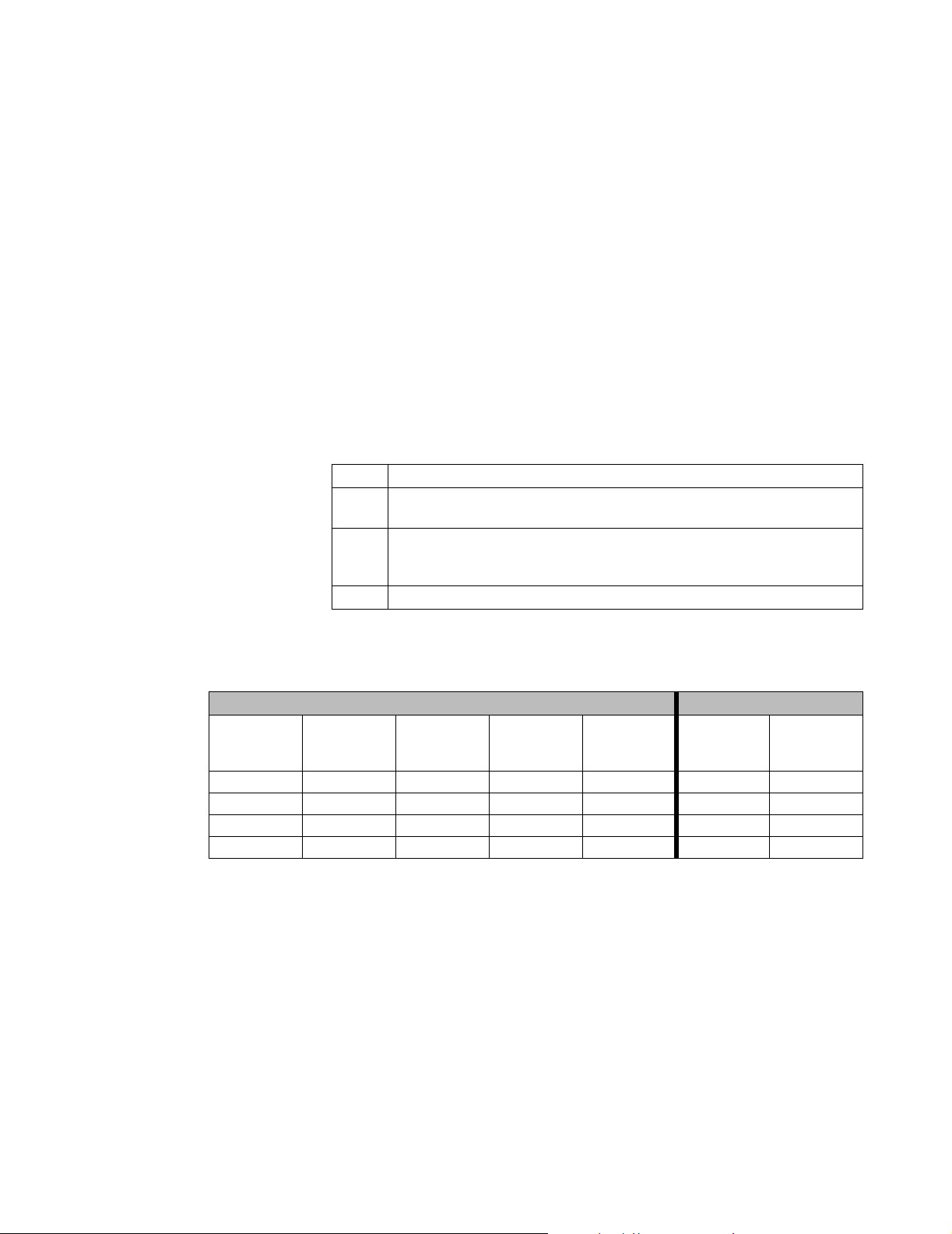
Performance Procedures
SpO2
Performance
Dynamic
Operating
Range Test
SpO2 testing includes the following tests:
• Dynamic Operating Range
• LED Excitation Test
Tools Needed for SpO
Tests:
2
• Clinical Dynamics Corp - SmartSat simulator (with Nellcor simulator cable)
•SpO
•SpO
adapter cable (M1943A)
2
reusable sensor, adult finger (M1191A)
2
The following test sequence verifies proper monitor operation over a range of input signals.
Step Action
1 Connect SpO
the SpO2 patient monitoring input connector.
2 Set the simulator as indicated in the table below. Verify that the monitor readings
are within the indicated tolerances. Allow the monitor several seconds to
stabilize the readings.
3 Turn the monitor Off.
simulator cable to the SpO2 adapter cable. Connect the cable to
2
Table 4-1. Settings and Monitor Indications
Simulator Settings Monitor Indications
SpO2% Pulse Rate
81 36 120 200 0.50% 79-83* 33-39*
81 112 120 200 5.00% 79-83* 109-115
81 201
81 201
a
a
Ambient
Light Freq
120 10 0.50% 79-83* 195-207*
120 200 5.00% 79-83* 195-207*
Ambient
Light Ac
Level
Modulation SpO
2
Pulse Rate
An * indicates values that produce an alarm. Press the Alarm Silence button to temporarily
silence the audible alarm.
a. For the pulse rate setting of 201 bpm, the pulse rate tolerance of 195 to 207 bpm is greater than ±3 bpm accuracy
specification on the monitor, due to the performance characteristics of the simulator.
Testing the Monitor
4-27
Page 78

Performance Procedures
LED Excitation
Test
This procedure uses normal system components to test circuit operation. A SpO2, adult
finger, reusable sensor is used to examine LED intensity control. The red LED is used to
verify intensity modulation caused by the LED intensity control circuit.
Step Action
1 Connect an SpO
2Press the On/Standby button to turn the monitor On.
3 After the monitor completes its normal power-up sequence, verify that the sensor
LED is brightly lit.
4 Slowly move the sensor LED in proximity to the photo detector element of the
sensor. Verify, as the LED approaches the optical sensor, that the LED intensity
decreases.
5 Open the sensor and take note that the LED intensity increases.
6 Repeat Step 5 and the intensity again decreases. This variation is an indication
that the micro-processor is in proper control of LED intensity.
7 Turn the monitor Off.
sensor to the monitor.
2
4-28 Testing the Monitor
Page 79

Performance Procedures
CO2
Performance
This test checks the performance of your CO
calibration equipment that can be ordered (contact your Philips representative). Refer to the
documentation accompanying the equipment for detailed instructions. The procedure is summarized in
the following steps:
measurement for the monitor. This test uses
2
• Barometric Pressure Check and Calibration, if required
• Leakage Check
• Pump Check
• Flow Check and Calibration, if required
•CO
•CO
Cal Check and Calibration, if required
2
Cal Verification using Cal 2 gas
2
Note
Allow 5 seconds between individual service procedures in order to ensure stable equipment
conditions.
Tools Needed for CO
Tests:
2
• Screwdriver
• Tweezers
• Cal 1 gas (5% CO
• Cal 2 gas (10% CO
)
2
)
2
• Cal gas flow regulator
•Cal tube
You also need a local barometric pressure rating received from a reliable local source, such as
an airport, regional weather station, or hospital weather station. The pressure rating must be
located at the same altitude as the hospital.
Note
All steps must be performed in the same session.
Testing the Monitor
4-29
Page 80

Performance Procedures
Documenting
The following table lists the CO2 tests and summarizes how to document the test results.
CO2 Test
Results
Test Expected Test Results What to record on service record
Barometric Pressure Check X1 = difference between the reference
pressure and the measured ambient
pressure displayed on the monitor
(-12 mmHg < X1 < +12 mmHg)
Leakage Check parts 1 and 2 X2 = value of part 1 leakage check on
flowmeter (X2 </= 4.0 ml/min)
X3 = value of part 2 leakage check on
flowmeter (X3</= 4.0 ml/min)
Pump Check X4 > 120 mmHg below the ambient
pressure
Flow Rate Check X5 = CO
<65 ml/min).
Gas Measurement Calibration
CO
2
Check
Calibration Verification X7 = difference between measured
X6 = difference between measured
CO
on 5% CO2 cal. gas (X7<2.6 mmHg,
or 0.35 kPa)
CO
on 10% CO2 cal. gas.
flow rate (42.5 ml/min <X5
2
value and calculated value, based
2
value and calculated value, based
2
: P/X1/X2/X3/X4/X5/X6/X7
PCO
2
or
PCO2: F/X1/X2/X3/X4/X5/X6/X7
P = passed, F = failed
X1: xx (two digits)
X2: x.x
X3: x.x
X4: xxx
X5: x.x
X6: x.x
X7: x.x
(X7±{0.07 x value calculated})
4-30 Testing the Monitor
Page 81

Performance Procedures
Barometric
Pressure
Check and
Calibration
Check the barometric pressure value in the CO
Step Action
1Enter the Power-Up Defaults Menu (see ““Power-Up Defaults Menu” on
page 5-3“for instructions on accessing this menu).
2 Select the Enter Diagnostic Mode? option.
3 From the popup menu, select Yes. The Diagnostic Menu displays.
4 Select the CO
5 Connect a FilterLine to the CO
activates the pump in the CO
6 Check the status line at the top of the screen. It will display "CO
mmHg (ambient/cell) xxx/yyy" where xxx is the ambient pressure and yyy is the
measured cell pressure. The values are displayed with a resolution of 2 mmHg
(0.3 kPa) up to 475 mmHg (63.2 kPa) and a resolution of 1 mmHg (0.1 kPa)
from 475 mmHg (63.2 kPa) to 825 mmHg (109.7 kPa). Check whether the
ambient pressure (X1) matches (within the acceptable tolerance of ±12 mmHg)
the reference value you have received. If so, proceed to the “Leakage Check”. If
the value is not correct, calibrate as follows.
7 Select Set Barometric Pressure (mmHg). An adjustable value in mmHg is
activated.
8 Select the value that matches the reference value received from a reliable local
source, such as an airport, regional weather station or hospital weather station.
9 If the selected value is not with ±12mmHg (1.6 kPa) of the current measured
ambient pressure, verify the reference value by getting another reading from a
different source. If the ambient pressure displayed also differs from the new
reference by more than ±12mmHg (1.6 kPa), the CO
replaced.
10 Confirm the barometric pressure setting by clicking on the adjusted value so that
it is no longer highlighted.
11 Check that the ambient pressure displayed in the CO
the screen is the same as the value that you selected from the list in Step 8.
Test option.
2
module as follows:
2
patient monitoring input connector. This
2
module.
2
pressure in
2
module should be
2
Pressure line at the top of
2
Testing the Monitor
4-31
Page 82

Performance Procedures
Leakage
Check
The Leakage Check consists of two parts:
• Part 1 - Checking the tubing between the pump outlet and the
CO
module outlet.
2
• Part 2 - Checking the tubing between the pump inlet and the FilterLine inlet.
Note
Check the flowmeter’s user guide for details on how to make a correct flow reading.
Part 1
Step Action
1 Check the ambient and cell pressure shown in the status line on the screen. The
cell pressure should be approximately 20 mmHg (2.7 kPa) lower than the
ambient pressure.
2 Connect the flowmeter outlet to the FilterLine inlet using a flexible connecting
tube.
3Block the CO
display. The value on the flowmeter (X2) should decrease to between 0 and 4 ml/
minute. If the value is not within the tolerance limits, there is a leakage between
the pump outlet and the CO
4 If a leakage is found in Step 3, open the CO
connections at the pump outlet and the module CO2 gas outlet. If the connections
are good, then there is leakage in the module and the CO2 module must be
exchanged.
module outlet using your fingertip and observe the flowmeter
2
module gas outlet.
2
module and check the tubing
2
Part 2
4-32 Testing the Monitor
Step Action
1 Disconnect the flowmeter from the Part 1 setup and connect the flowmeter inlet
to the CO
2 Leave the FilterLine connected to the CO
module gas outlet.
2
module inlet.
2
3 Block the inlet of the FilterLine using your fingertip and observe the flowmeter
display. The value on the flowmeter (X3) should decrease to between 0 and 4 ml/
minute. If the value is within the tolerance limits, there are no leakages and the
leakage check is completed. You can proceed to the “Pump Check”.
4 If the value is not within the tolerance limits, there is a leakage between the
FilterLine inlet and the pump inlet.
5 Check the FilterLine connections and open the monitor to check the tubing
connections at the pump inlet and the CO
module gas inlet. If the connections
2
are good, try replacing the FilterLine and repeating the leakage check. If the
situation remains, there is a leakage in the tubing and the CO
module must be
2
exchanged.
Page 83

Pump Check
Flow Rate
Check and
Calibration
Performance Procedures
Step Action
1 Connect the flowmeter inlet to the CO
2 Connect the FilterLine to the CO
module gas outlet.
2
module inlet.
2
3 Block the inlet of the FilterLine using your fingertip and observe the cell
pressure to the right of the slash symbol on the top row of the CO
Test display
2
screen.
The cell pressure (X4) should be more than 120 mmHg below the ambient
pressure shown. If the pressure difference is less than 120 mmHg, the pump is
not strong enough and should be replaced (regardless of the Pump Op Time).
Step Action
1 Connect the flowmeter to the CO
2 On the flowmeter, check the flow that the CO
FilterLine.
2
Pump draws (X5). The nominal
2
value is 50; the acceptable limits are 42.5 and 65 ml/minute. If the value is
within these limits, proceed to the CO
Gas calibration check. If not within the
2
limits, calibrate as follows.
3 Select Flow Rate Check and Calibration. Adjust the flow in the monitor by
selecting Increase Flow or Decrease Flow until it is as close as possible to 50
ml per minute as indicated on the flowmeter gauge. The pump voltage displayed
on the second row of the CO
Test screen will vary as the flow is changed.
2
4 When you are satisfied that the flow is set as close as possible to 50 ml per
minute, select Store Flow to confirm the setting
Note
If the adjusted flow is not stored within 60 seconds of the adjustment, the old flow setting is
restored. If the flow cannot be adjusted to within tolerance, the pump should be replaced. If
the flow adjustment still cannot be made, this indicates a fault in the
CO
module, which must
2
be replaced.
Testing the Monitor
4-33
Page 84

Performance Procedures
CO2 Gas
Measurement
Calibration
Check
After switching the monitor on, or after turning on the etCO2 On/Off setting in the etCO2
frame, wait at least 20 minutes before checking the calibration.
Step Action
1 Check that the 5% calibration gas and flow regulator are connected.
2 Calculate the expected measurement value in mmHg as follows:
0.05 x (ambient pressure) / 1.03 = value mmHg
i.e. 0.05 x 736 mmHg / 1.03 = 35.7 mmHg (with an ambient pressure of 736
mmHg)
Note: Dividing by 1.03 compensates for the dry calibration gas at room
temperature, relative to breath gases containing water vapor and at body
temperature.
3 Select CO
progress" to disappear. Open the valve on the flow regulator to allow 5% CO2
gas to flow into the monitor. Allow the displayed CO
Test menu) to stabilize.
4 Check that the CO
±2.6 mmHg. If the value is outside the tolerance, calibrate as described in Step 9
to 13.
5 Disconnect the 5% calibration gas and connect the 10% calibration gas.
6 Calculate the expected measurement value and tolerance in mmHg as follows:
Calibration. Wait for the status message "CO2 module reset in
2
value (third row of CO2
2
value on the monitor matches the calculated mmHg value
2
0.1 x (ambient pressure) / 1.03 = value mmHg
±0.07 x (value mmHg) = tolerance
i.e. 0.1 x 737 mmHg / 1.03 = 71.6 mmHg (with an ambient pressure of 737
mmHg)
±0.07 x 71.6 mmHg = ±5.01 mmHg tolerance
7 Open the valve on the flow regulator to allow 10% CO
gas to flow into the
2
monitor. Allow the value to stabilize.
8 Check that the value on the monitor (X6) matches the calculated mmHg value
within the calculated tolerance. If so, the CO
module is correctly calibrated. If
2
the value is outside the tolerance, calibrate as follows.
9 If not already connected, connect the 5% calibration gas.
10 Select CO
message "CO
Calibration to enter the Calibration sub-menu. Wait for the status
2
module reset in progress" to disappear.
2
11 Select the value for the calibration gas (The default value is 5%).
12 Select Start Calibration and open the valve on the calibration gas to allow CO
gas to flow into the monitor. Allow the value to stabilize before the start of the
calibration. Leave the valve open until the monitor gives a prompt that the gas
can be removed.
13 The CO
module calibrates and prompts when calibration is successful.
2
2
4-34 Testing the Monitor
Page 85

Calibration
Verification
Performance Procedures
Step Action
1 Reopen the 5% gas valve and allow the value to stabilize.
2 Check that the value displayed on the monitor is correct and within the tolerance
(see Step 2 in above section).
3 Disconnect the 5% calibration gas and connect the 10% calibration gas.
4 Open the valve on the flow regulator to allow 10% CO
monitor. Allow the value to stabilize.
5 Check that the value displayed on the monitor (X7) is correct and within the
tolerance (see Step 6 above). If one or both values are not within tolerances, the
module must be exchanged.
CO
2
gas to flow into the
2
Reset Pump
Operating
Time Counters
If the pump in the CO2 module is replaced, the Pump Operating Time counter should be reset
to start counting operating time for the new pump.
Step Action
1 In the CO2 Test menu, select Pump Op Time.
2 Select Reset to Zero.
Note
When the Pump Op Time has been reset a "CO2 Equipment Malfunction" INOP will be
generated on restarting the monitor. To clear this INOP you must perform a flow check and
store the flow in Diagnostic Mode (select Store Flow).
Testing the Monitor
4-35
Page 86
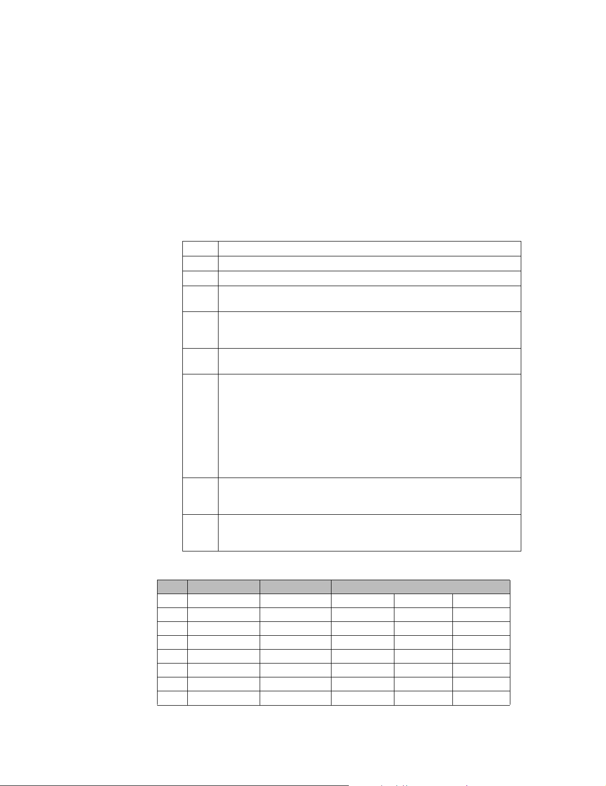
Performance Procedures
Serial Interface and Nurse Call Signal Test
Perform the following procedure to test the serial port voltages. The test is qualitative and
only verifies that the serial interface port is powered correctly, and that the Nurse Call signal
is operational. The serial connector is a male DB-9 located on the monitor’s rear panel,
identified by the RS-232 symbol.
Tools Needed:
• Clinical Dynamics Corp - SmartSat simulator (with Nellcor simulator cable)
•SpO
adapter cable (M1943A)
2
Step Action
1 Turn the monitor On.
2 Set up the DMM with the function set to VDC at a range of 10 volts.
3 Connect the DMM negative lead to connector pin 5 (GND), or the shell of the
RS-232 connector.
4 Referring to Table 4-2, Serial Interface Voltages, connect the DMM positive
lead to each pin in turn, and verify the voltage values listed. Voltage for pin 9 is
that listed from the No Alarm condition.
5 Connect SpO
the SpO
6 Set the simulator switches as follows:
simulator cable to the SpO2 adapter cable. Connect the cable to
2
patient monitoring input connector.
2
Item Setting
Oximeter Nellcor
SpO2%
BPM 36
Pulse Mod 0.50%
7 Verify that the monitor is responding to the SpO
audible alarm is sounding. If desired, press the Alarm Silence button to
temporarily silence the audible alarm.
8 Connect the DMM positive lead to pin 9 and verify the voltage value listed in
Table 4-2, Serial Interface Voltages. The voltage for pin 9 is that listed for the
Alarm Underway condition.
81
simulator signal and the
2
Table 4-2. Serial Interface Voltages
Pin Signal Direction Measurement (V)
Min. Typical Max.
1 not used -0.4 0.0 0.4
2 RXD <<< input -0.4 0.0 0.4
3 TXD<<< output -5.0 -7.0 -15.0
4 DTR<<< output 5.0 7.0 15.0
5 GND -0.4 0.0 0.4
6 DSR<<< input -0.4 0.0 4.0
7 RTS>>> output 5.0 7.0 15.0
4-36 Testing the Monitor
Page 87

Performance Procedures
Pin Signal Direction Measurement (V)
8 CTS<<< input -0.4 0.0 0.4
9 Alarm Out>>>
(no alarm)
9 Alarm Out>>>
(alarm underway)
output -5.0 -7.0 -15.0
output 5.0 7.0 15.0
Testing the Monitor
4-37
Page 88

Performance Procedures
ECG Sync Test
This test checks the performance of ECG synchronization between the monitor and a
defibrillator. The ECG sync performance test is required once every year and when the
monitor is repaired or when the monitor’s parts are replaced.
Tools Needed:
• Dynatech Nevada MedSim 300 or equivalent simulator
• Defib Sync Cable (M4820A) or Switchcraft 850
• Switchcraft 750
Two sections are needed to complete the connection from the monitor to the simulator.
1. If a Defib Sync Cable is available, connect it the ECG Sync output on the monitor, then
to the Switchcraft 750.
or
If a Switchcraft 850 is available, connect it the ECG Sync output on the monitor, then
to the Switchcraft 750.
2. Connect the Switchcraft 750 to the SYNC/A PACE input on the simulator
Connect to the monitor Connect to the simulator
Defib Sync Cable Switchcraft 750
Switchcraft 850 Switchcraft 750
Step Action
1 Connect the ECG leads and trunk cables between the monitor and the simulator
(as described above).
2 Turn on the monitor and the simulator
3 On the simulator main menu select DEFB, then CARD to set the simulator to
Defibrillator Tests/Cardioversion.
4Press Start to begin the test. If the monitor is working properly, the following
sequence of text messages will appear on the simulator over a period of
approximately 3 seconds: "cardioversion: afib", "cardioversion: sync ok", and
"cardioversion: converted" (this message will persist on the simulator)
5 If the monitor isn’t working properly, messages such as the following may
appear: "cardioversion: vfib", "cardioversion: late".
4-38 Testing the Monitor
Page 89

Patient Safety Tests
Philips safety tests meet the standards of, and are performed in accordance with IEC 60601-1,
Clause 19 (EN60601-1, Second Edition, 1988; Amendment 1, 1991-11, Amendment 2, 1995-
03).
The C3 patient monitor is a Class I device. It requires a protective earth (ground) wire. Keep
this in mind when performing the following test procedures.
There are two categories of safety tests:
• Ground Integrity
• Electrical Leakage
Patient Safety Tests
Ground Integrity
Table 4-3. Ground Integrity
Test or “Inspection” to Perform Expected Test Results
Protective Earth
See “Safety Test Diagram - Protective
Earth” on page 4-40.
With mains cable:
Maximum impedance = x <= 100 mOhms
Testing the Monitor
4-39
Page 90
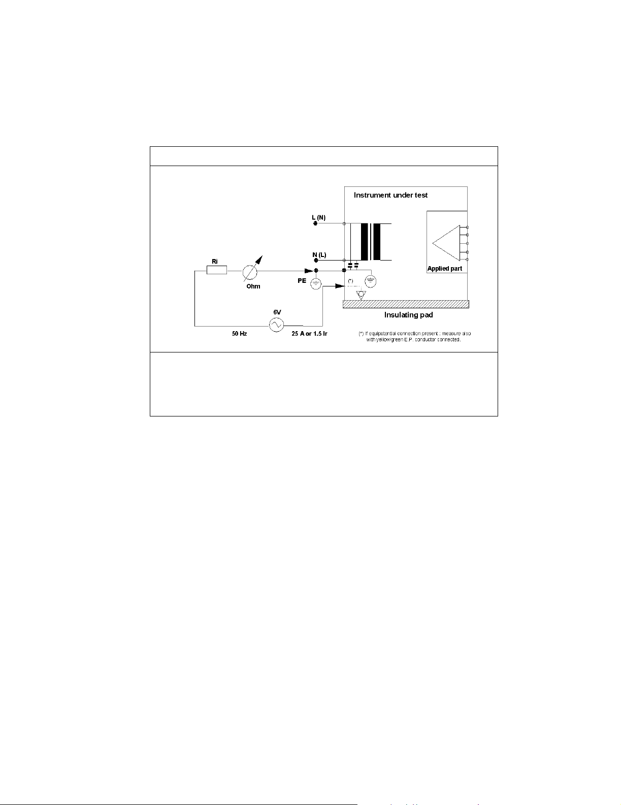
Patient Safety Tests
Figure 4-1 Safety Test Diagram - Protective Earth
Test or Inspection to Perform
Measures impedance of Protective Earth (PE) terminal to all exposed metal parts of IUT,
which are for safety reasons connected to the Protective Earth (PE). Max. 100 mOhm. Test
current 25 Amps applied for 5 to 10 seconds. We recommend to flex the main cable during
the test in order to identify potential bad contact or damage of the earth wire. Safety test
according to EN60601-1 (Clause 18). Report largest value.
What to record on this service record:
S(1): P or S(1): F
4-40 Testing the Monitor
Page 91

Patient Safety Tests
Electrical Leakage
Earth Leakage
Current
The following tests verify the electrical leakage of the monitor:
• Earth Leakage Current
• Enclosure Leakage Current
• Patient Leakage Current
• Patient Source Current, with Mains Voltage on the Applied Part
WarningWarning
Perform all leakage tests any time the unit is opened.
This test is in compliance with IEC 60601-1 (Earth Leakage Current). In locations where
mains voltage is 100-120 volts, the applied voltage is 132 volts. In locations where mains
voltage is 220-240 volts, the applied voltage is 264 volts. The applied AC frequency should
be the same as the local mains (50 or 60 Hz).
All measurements shall be made with the power switch in both On and Off positions.
1. Connect the monitor AC plug to the electrical safety analyzer as recommended by the
analyzer operating instructions.
2. Perform test as recommended by analyzer operating instructions.
Earth leakage current is measured under various conditions of the AC mains and protective
earth conductor. For each condition, the measured leakage current must not exceed that
indicated below.
Table 4-4. Earth Leakage Current Values
Test Condition Polarity Allowable Leakage Current
Normal Normal 300 µA
Reversed 300 µA
a
S.F.C
Open Supply
a. S.F.C = Single Fault Condition
Normal 1000 µA
Reversed 1000 µA
What to record on the service record:
S(2): P or S(2): F
Testing the Monitor
4-41
Page 92

Patient Safety Tests
Enclosure
Leakage
Current
This test is compliance with EN60601-1 (Enclosure Leakage Current). Test at 110% of the
nominal line voltage.
Step Action
1 Connect the AC mains power cord to the analyzer as recommended by the
analyzer operating instructions.
2 Using the appropriate test cable, connect the analyzer to either of the screws on
the back of the monitor, next to the handle.
3 Turn the monitor on.
4 Perform the test as recommended by the analyzer operating instructions.
The analyzer leakage current indication must not exceed the values listed below.
Table 4-5. Enclosure Leakage Current
EN60601-1 (1990 + A1, A2, A11, A12, A13) and UL2601 (2
Test Condition Polarity Allowable Leakage Current
Normal Normal 100 µA
Reversed 100 µA
1
S.F.C
Open
Normal 300 µA
nd
Ed. 1997) US Deviations
Protective Earth
Reversed 300 µA
What to record on your service record:
S(3): P or S(3): F
4-42 Testing the Monitor
Page 93

Patient Safety Tests
Patient
Leakage
Current
This test measures patient leakage current in accordance with EN60601-1, Clause 19, for
Class I, type CF equipment. Patient leakage current in this test is measured from any
individual patient connection to earth (power ground).
This test requires a sample patient cable for each device parameter. These must be configured
as recommended by the safety analyzer operating instructions.
Step Action
1 Configure the electrical safety analyzer as recommended by the analyzer
operating instructions.
2 Connect the monitor’s AC mains power cord to the analyzer as recommended by
analyzer operating instructions.
3 Connect the ECG test cable between the ECG connector on the monitor and the
appropriate input connector on the analyzer.
4 Turn the monitor On.
5 Perform the test as recommended by the analyzer operating instructions.
Patient leakage current is measured under various conditions of the AC mains
and protective earth conductor. For each condition, the measured leakage current
must not exceed that indicated below.
Repeat the test for SpO2 and temperature patient connections, using
6
appropriate test cables.
Table 4-6. Patient Leakage Current Values
Allowable Leakage
Test Condition Polarity
Normal Normal 10 µA
Reversed 10 µA
S.F.C.(Open Earth/Ground) Normal 50 µA
Reversed 50 µA
Current (Max.)
Type CF
What to record on the service record:
S(4): P or S(4): F
Testing the Monitor
4-43
Page 94
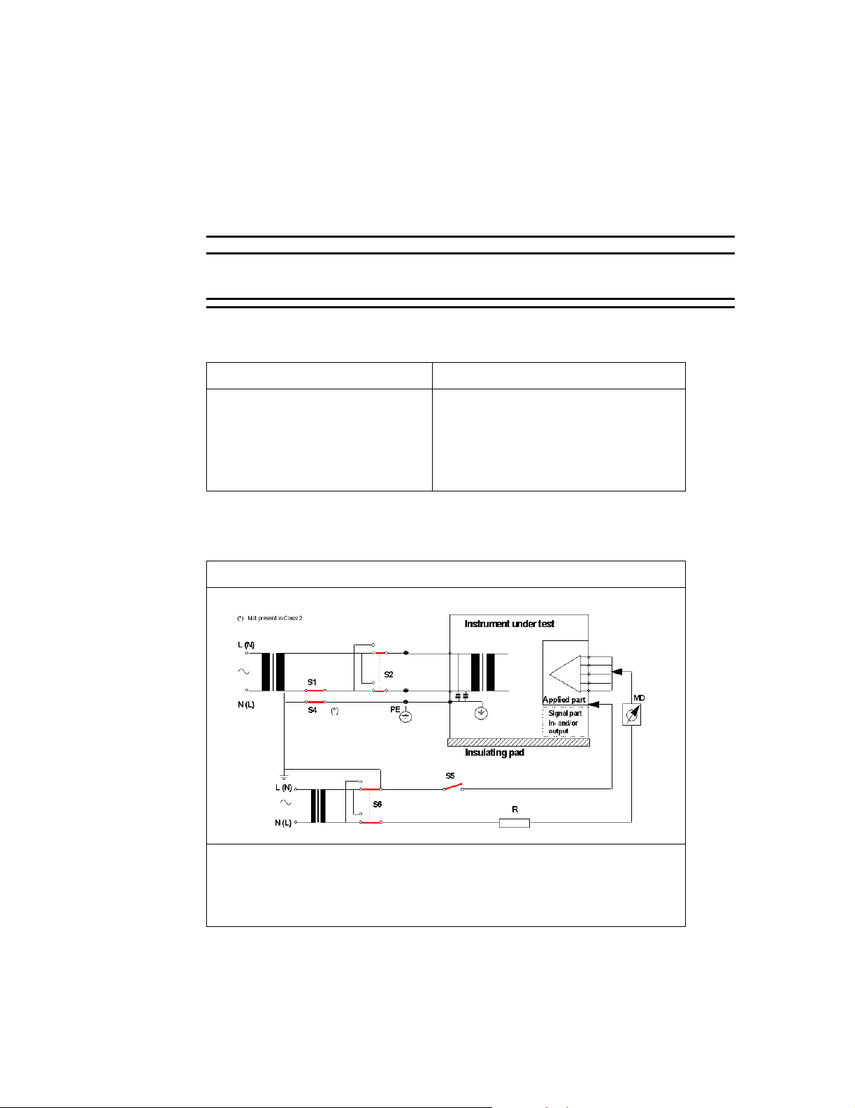
Patient Safety Tests
Patient
Leakage
Current, with
Mains Voltage
on the Applied
Part
This test measures patient leakage current in accordance with EN60601-1, Clause 19, for
Class I, type CF equipment. In this test, 110% of mains voltage is applied between each
patient connection and earth (power ground). Patient leakage current is then measured from
any individual patient connection to earth.
WarningWarning
AC mains voltage is present on the applied part terminals during this test. Exercise
caution to avoid electrical shock hazard.
Table 4-7. Safety Tests - Patient Leakage Current, with Mains Voltage on the
Applied Part
Test or “Inspection” to Perform Expected Test Results
Patient Leakage Current - AC
See “Safety Test Diagram - Patient
Leakage Current - AC” on page 4-44
Maximum leakage current = x
<= 50 µA @ 250V (IEC601-1 or UL2601-1)
Test at 110% of the nominal line voltage.
Figure 4-2 Safety Test Diagram - Patient Leakage Current - AC
Test or Inspection to Perform
Measures patient leakage current from Applied Part to earth caused by external mains
voltage on Applied Part with switch S5 open and closed. Each polarity combination
possible is tested using S2 and S6.
Safety test according to EN60601-1 (Clause 19.4.h). Report largest value.
What to record on the service record:
S(5): P or S(5): F
4-44 Testing the Monitor
Page 95

Patient Safety Tests
Testing the Monitor
4-45
Page 96

Patient Safety Tests
4-46 Testing the Monitor
Page 97

5
Configuring the Power-up Defaults Menu
This chapter discusses the use of the Power-up Defaults Menu to configure power-on default
settings. It also explains how to use Diagnostic Mode to obtain service-related information
about the monitor.
Configuring the Power-up Defaults Menu 5-1
Page 98

General Safety Information
General Safety Information
WarningWarning
A blood pressure cuff, connected to the monitor, should never be applied to a human
being while the monitor is in Diagnostic Mode. Injury could result.
A FilterLine, connected to the monitor, should never be applied to a human being while
the monitor is in Diagnostic Mode. Injury could result.
Caution
In addition to restoring factory defaults, this procedure clears the contents of trend memory.
Note
Before performing the first step, read this procedure COMPLETELY.
5-2 Configuring the Power-up Defaults Menu
Page 99

Power-Up Defaults Menu
The purpose of the Power-up Defaults Menu is to allow the authorized user to create a
power-up default for each setting in the monitor. Power-up defaults are the settings in effect
each time the monitor is power on. After you enter the Power-up Defaults Menu,
physiological monitoring is terminated. The screen layouts do not display any information
associated with normal monitoring operation.
After configuring the main monitoring screen and connecting the appropriate accessories, as
not in the C3 Information for Use guide, use the following procedure to configure the
power-up default settings for the monitor:
Step Action
1 From the main monitoring screen, use the navigation wheel to highlight the
2 From the Set-Up Menu, select Enter Power -up Default Menu. A popup box
3 Use the wheel to enter the passcode. The passcode is: 2 1 5.
Power-Up Defaults Menu
Setup icon. Press the wheel to select the icon.
displays.
Note: This passcode is configured at the factory and CANNOT be changed.
4 The Power-Up Defaults Menu displays.
POWER-UP DEFAULT MENU
Accept Current Settings?
Selected Audio Off (Make Available)
Audio Off (Make Available)
Auto-Set Limits (Make Available)
Audio Pause Period (180s)
Enter Diagnostic Mode?
Language
Enter Demo Mode?
Return
The available menu items are described in the next section. You can configure
these menu items as desired.
5 After making the desired change, highlight Access Current Settings? Press the
wheel to select this option.
6 From the popup menu, select Yes.
7 Select Return.
After selecting Return, a notice displays instructing you to power down the
monitor. Next time you power on, the changes you made to the defaults are
implemented.
Configuring the Power-up Defaults Menu
5-3
Page 100

Power-Up Defaults Menu
Menu Options
Below are the menu options you can configure from the Power-up Defaults Menu.
Menu Item Choices Explanation
Accept Current Settings Yes
No
Selected Audio Off Make Available (default)
Deny Access
Audio Off Make Available (default)
Deny Access
Auto-Set Limits Make Available (default)
Deny Access
If Yes is chosen, the current monitor
settings become the power-up defaults.
If Make Available is chosen, audible
alarms are permanently silenced for a
particular parameter via the Alarm
Limits Menu.
Some institutions may want to prevent
audible alarms from being permanently
silenced. If so, select Deny Access.
If Make Available is chosen, Alarm
Suspend Mode can be invoked by
pressing and holding the Alarm Silence
button for 2 seconds.
Some institutions may wish to prevent
Alarm Suspend from being invoked. If so,
select Deny Access.
If Make Available is chosen, Auto-Set
Limits are invoked via the Alarm/Limits
Menu.
Some institutions may wish to prevent
Auto-Set Limits from being invoked. Is
so, select Deny Access.
Silence Period 30, 60, 90, 120, 180 s (default) Time is indicated in seconds. Pressing the
front panel Alarm Silence button
temporarily silences audible alarms for
the time indicated
Enter Diagnostic Mode Yes
No
Language
Return When selected, the Power-Up Defaults
a
a. Although the language choices are shown here in English, they display on the screen in their
English, French, German,
Italian, Japanese, Portuguese,
Spanish, Russian, Chinese,
Dutch, Turkish, Arabic,
Norwegian, Swedish, Finnish,
Polish, Czech
respective language and script on the Boot Up screen and in the Power-Up Defaults Menu.
If Yes is chosen, the Power-Up Defaults
Menu is existed and the Diagnostic
Menu displays. For more information see
“Diagnostic Mode” on page 5-5.
All text shown on the screen is in the
selected language. The selected language
is effective the next time the monitor is
powered up.
Menu is immediately exited and you are
instructed to power down the monitor.
5-4 Configuring the Power-up Defaults Menu
 Loading...