

Philips 820, 825 Service Manual
Départ. Techni cal support- CM640 PROCEDURE COMPANY RESTRICT E D
PHILIPS Con sumer
Communications
Centre du Mans
Service Repair Support
SERVICE MANUAL
Repair for Cellular Telephone
Fisio 820 - Fisio 825
LEVEL 2
VY-V-640-82x
Page : 1 of 71
Langue : EN
Date : 25/02/03
PHILIPS ELECTRONICS N.V. 1999 VY-V-640-82x
All rights reserved. Reproduction in whole
or in part is prohibited without the written
consent of the copyright owner.

Départ. Technic al s uppo rt- CM640 PROCEDURE COMPANY RESTRICTED
PHILIPS Con sumer
Communications
Centre du Mans
Last updates :
Service Repair Support
VY-V-640-82x
Page : 2 of 71
Langue : EN
Date : 25/02/03
SERVICE Manual
DATE MODIFICATION PAGE
08/04/02 CREATION
26/08/02 Window assembl y i nstr uc tions Page 64-65
14/02/03
- Add Fisio 825 picture
- Add Fisio 825 test consumption
- Part list chapter
Page 1
Page 42
Page 70
25/02/03 Cradle 12NC code corr ec tion Page 5
PHILIPS ELECTRONICS N.V. 1999 VY-V-640-82x
All rights reserved. Reproduction in whole
or in part is prohibited without the written
consent of the copyright owner.

Départ. Technic al s uppo rt- CM640 PROCEDURE COMPANY RESTRICTED
PHILIPS Con sumer
Communications
Centre du Mans
Service Repair Support
VY-V-640-82x
Page : 3 of 71
Langue : EN
Date : 25/02/03
CONTENTS
1.0 PURPOSE.................................................................................................................................................................5
2.0 SCOPE ......................................................................................................................................................................5
3.0 REFERENCE............................................................................................................................................................5
4.0 GLOSSARY/ACRONYM LIST...............................................................................................................................5
5.0 T EST EQUIPME NT AND TOOLS..........................................................................................................................5
6.0 T EST AND INSPECTION PLAN............................................................................................................................6
6.1 User Interface Test..................................................................................................................................................6
6.2 RF Test...................................................................................................................................................................6
7.0 BEFORE STARTING...............................................................................................................................................8
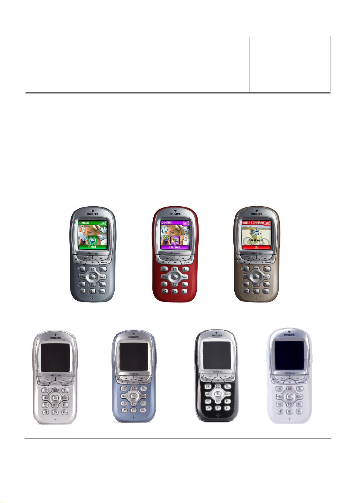
7.1 Description Of The Transceiver...............................................................................................................................8
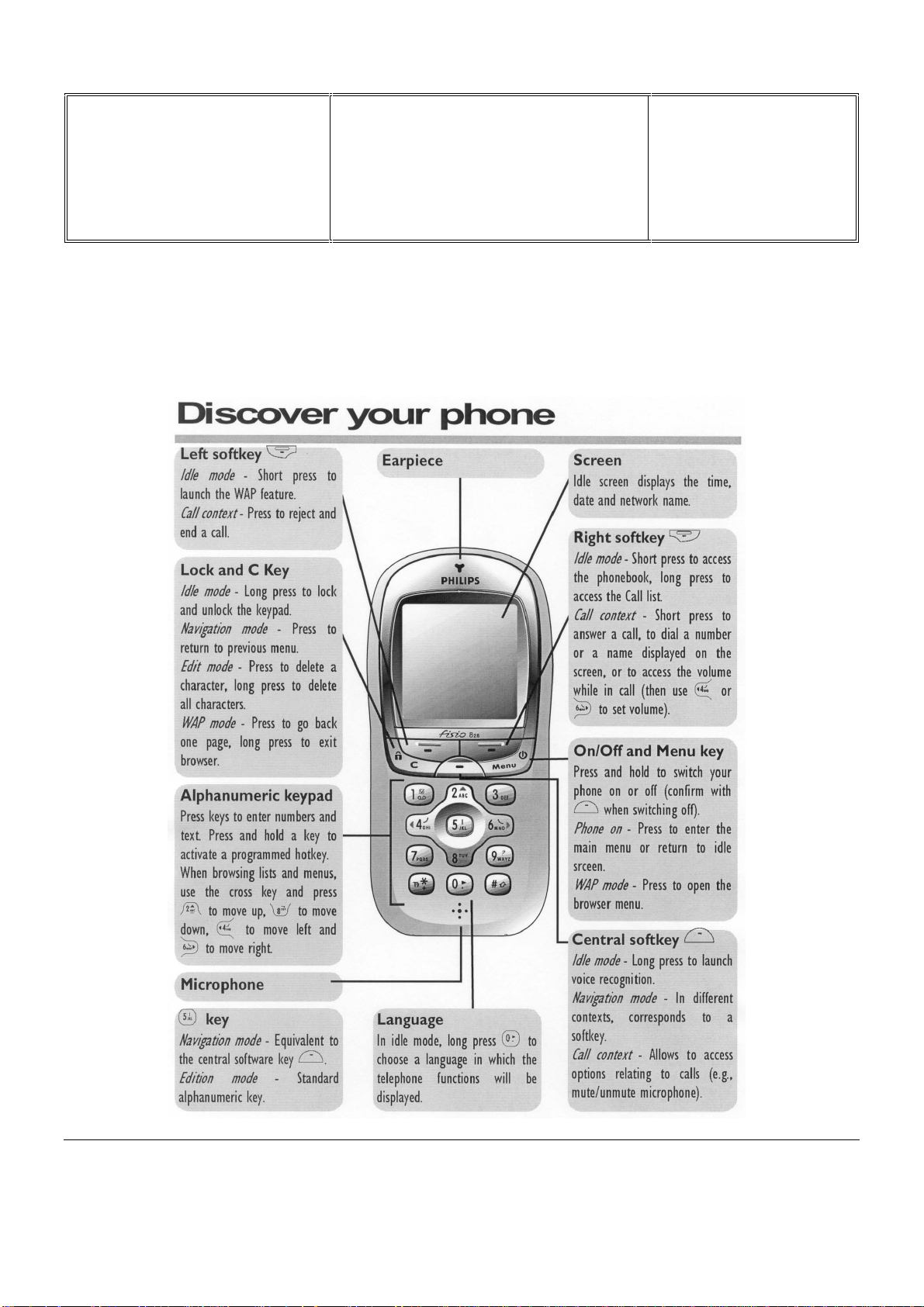
7.2 Description Of The Display.....................................................................................................................................9
7.3 Usi ng The Caro u sel...............................................................................................................................................10
7.4 Inserting The MICRO-SIM Card...........................................................................................................................11
7.5 Inse rt ing The Battery.............................................................................................................................................11
7.6 Removing The B attery ........................................................................................................ ...................................12
7.7 Charging The Battery............................................................................................................................................12
7.8 W@P Introduction............................................................................................................ .................................... 13
7.9 GPRS Introduction................................................................................................................................................15
7.10 BLUETOOTH Introduction...................................................................................................................................22
7.11 E-MAIL Introduction............................................................................................................................................30
8.0 TE ST PROCE DURE S ............................................................................................................................................31
8.1 Initial Functional Check for Fisio 820 & Fisio 825.................................................................................................31
8.2 RF Test.................................................................................................................................................................35
8.3 Battery Charging (IGN : Ignition) / Current Consumption......................................................................................41
8.4 W@P Test Procedure............................................................................................................................................43
8.5 Blue t o oth Test Procedu re......................................................................................................................................49
8.6 E-MAIL Test Procedure........................................................................................................................................50
9.0 ASSE MBLY / DISMANTLEMENT PROCEDURES............................................................................................54
9.1 Dismantlement......................................................................................................................................................54
9.2 Assembly..............................................................................................................................................................60
Exploded view of the transceiver ......................................................................................................................................66
10.0 SOLUTIONS IN CASE OF PROBLEMS DURING THE TESTS ........................................................................68
11.0 RECOMENDED PART LIST CT9888 FISIO820................................................................................................70
PHILIPS ELECTRONICS N.V. 1999 VY-V-640-82x
All rights reserved. Reproduction in whole
or in part is prohibited without the written
consent of the copyright owner.

Départ. Technic al s uppo rt- CM640 PROCEDURE COMPANY RESTRICTED
PHILIPS Con sumer
Communications
Centre du Mans
Service Repair Support
VY-V-640-82x
Page : 4 of 71
Langue : EN
Date : 25/02/03
12.0 RECOMENDED PART LIST CT9889 FISIO825................................................................................................70
ANNEX 1............................................................................................................................................................................71
PHILIPS ELECTRONICS N.V. 1999 VY-V-640-82x
All rights reserved. Reproduction in whole
or in part is prohibited without the written
consent of the copyright owner.

Départ. Technic al s uppo rt- CM640 PROCEDURE COMPANY RESTRICTED
PHILIPS Con sumer
Communications
Centre du Mans
Service Repair Support
VY-V-640-82x
Page : 5 of 71
Langue : EN
Date : 25/02/03
1.0 PURPOSE
This document establishes the functional t est and inspect ion procedures for the first level service repair of the
FISIO 820 transceiver (CT9888) and FISIO 825 transceiver (CT9889).
2.0 SCOPE
The test plan is appli c able to all levels of service repair of t he FISIO 820 transceiver (CT9888) and FISIO 825
transceiv er (CT9889).
3.0 REFERENCE
None.
4.0 GLOSSARY/ACRONYM LIST
Window or Bezzel Protective pl astic ov er the LCD display
SW Sof tware
PN Hardware Configur ation of the Mobile
CN Matrix for Types of SW used on the different hardware
HW Hardware
ASC Authorized Service Center
NSC National Servic e Center
Test SIM Card Used for functionality of PHILIPS Mobile Phones
Test SIM Card « SP » SIM Card used to simulate t he user int erface and enable radio tests
5.0 TEST EQUIPMENT AND TOOLS
Equipment / Tools
- Production T est SIM Card - Part No. : 4311 255 00781
- Test SIM Card « SP » - Part No. : 4311 255 00782
- W@b dismantling t ool - Part No. : 4311 255 21325
- Digital Multimeter - Recommended Model : Fl uk e (
- Digital Radiocommunication Tester.
Specific ation: with c urr e nt r e ad in g in mA .)
- Coupling system with shielded chamber.
Or
- Product cradle Ref:
CKFR82/P - Part No.: 9911 240 34509
PHILIPS ELECTRONICS N.V. 1999 VY-V-640-82x
All rights reserved. Reproduction in whole
or in part is prohibited without the written
consent of the copyright owner.

Départ. Technic al s uppo rt- CM640 PROCEDURE COMPANY RESTRICTED
PHILIPS Con sumer
Service Repair Support
Communications
Centre du Mans
6.0 TEST AND INSPECTION PLAN
The test plan is derived from the Product Test Reference of FISIO 820 and FI SIO 825.
6.1 User Interface Test
Use the Test SIM Card to test the transceivers as follows :
• On/Off button
• LCD Backlight
• Keyboard Test
• Buzzer Test
• Vibrator Test
• Audio Test
• Antenna
• LCD
• IMEI
• Tester Status/ E epr om Status
Test ( to measure the radiated power level. Not necessary when using an antenna coupler)
VY-V-640-82x
Page : 6 of 71
Langue : EN
Date : 25/02/03
With a fast Charger connected with the PRODUCT’s bottom connect or , check the full scrolling from one mode to
the next when charging IG N (Ignition) – Battery.
6.2 RF Test
The purpose of the radio test is to prove that the tested phone is compliant to the Standard.
The radio test must be performed with a
Digital Radio Test Set. The mobile has to
be set on the antenna coupler inside the
shielded chamber.
Or It can be tested using the pr oduc t
cradle (in this case a measurement of
the power radiated by the antenna has
to be performed)
PHILIPS ELECTRONICS N.V. 1999 VY-V-640-82x
All rights reserved. Reproduction in whole
or in part is prohibited without the written
consent of the copyright owner.

Départ. Technic al s uppo rt- CM640 PROCEDURE COMPANY RESTRICTED
PHILIPS Con sumer
Communications
Centre du Mans
Service Repair Support
VY-V-640-82x
Page : 7 of 71
Langue : EN
Date : 25/02/03
Use the Test SIM Card « SP »to test the following RF items
• GSM 900 / DCS 1800 band
• GPRS capability
• Bluetooth connectivity
In case the RF tester i s not suitable for GPRS tests, GSM900/DCS1800 test may be consider ed as suf ficient
provided that the sensiv ity tests are strengthened by reducing the RF level down to -104dBm.
RLC / MAC
BLER CS1 to CS4
This reasoning i s based on the fact that all
the protocol steps (GP RS att ac h, GPRS
detach, …) are achieved on the GSM/DCS
bands and validated by Philips Approval
department.
RRM
L1
[Sequencer]
The new parameter to chec k , int r oduc ed by
GPRS, would be BLER (Blocks Error Rate).
HARDWARE LAYER
Function book for DSP control]
[
As shown on the drawing, it inv olves more
modules than BER
DSP
Signals paths
BLER comp a r ed to BER
BER
Bluetooth tests consists only in a pairing test with another Bluetooth devic e (e.g. Bluetooth headset)
PHILIPS ELECTRONICS N.V. 1999 VY-V-640-82x
All rights reserved. Reproduction in whole
or in part is prohibited without the written
consent of the copyright owner.
Départ. Technic al s uppo rt- CM640 PROCEDURE COMPANY RESTRICTED
PHILIPS Con sumer
Communications
Centre du Mans
7.0 BEFORE STARTING
7.1 Description Of The Transceiver
Service Repair Support
VY-V-640-82x
Page : 8 of 71
Langue : EN
Date : 25/02/03
PHILIPS ELECTRONICS N.V. 1999 VY-V-640-82x
All rights reserved. Reproduction in whole
or in part is prohibited without the written
consent of the copyright owner.

Départ. Technic al s uppo rt- CM640 PROCEDURE COMPANY RESTRICTED
PHILIPS Con sumer
Communications
Centre du Mans
7.2 Description Of The Display
Service Repair Support
OPERATOR
ICONS BAR
CLOCK
DATE
VY-V-640-82x
Page : 9 of 71
Langue : EN
Date : 25/02/03
WAP
Names
PHILIPS ELECTRONICS N.V. 1999 VY-V-640-82x
All rights reserved. Reproduction in whole
or in part is prohibited without the written
consent of the copyright owner.
Départ. Technic al s uppo rt- CM640 PROCEDURE COMPANY RESTRICTED
PHILIPS Con sumer
Communications
Centre du Mans
Service Repair Support
VY-V-640-82x
Page : 10 of 71
Langue : EN
Date : 25/02/03
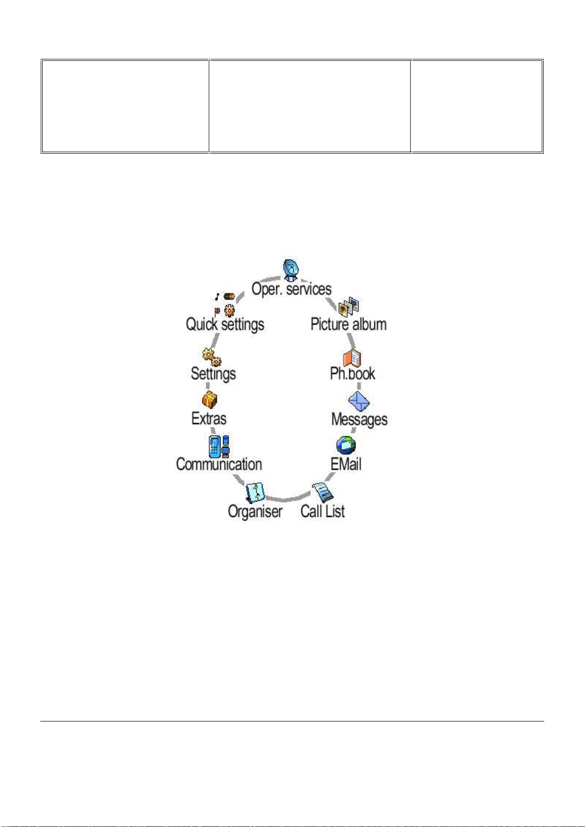
7.3 Using The Carousel
The carousel i s a circ ular loop of icons displayed on the screen. These i c ons provide access to the different m enus
and sub menus used to operate your phone.
PHILIPS ELECTRONICS N.V. 1999 VY-V-640-82x
All rights reserved. Reproduction in whole
or in part is prohibited without the written
consent of the copyright owner.
Départ. Technic al s uppo rt- CM640 PROCEDURE COMPANY RESTRICTED
PHILIPS Con sumer
Communications
Centre du Mans
7.4 Inserting The MICRO-SIM Card
First remove t he SIM card from its card holder.
Slide it into its slot, microchip facing
connectors, until its stops. Be careful that t he
clipped corner is in the identical position as on
the drawing.
Service Repair Support
VY-V-640-82x
Page : 11 of 71
Langue : EN
Date : 25/02/03
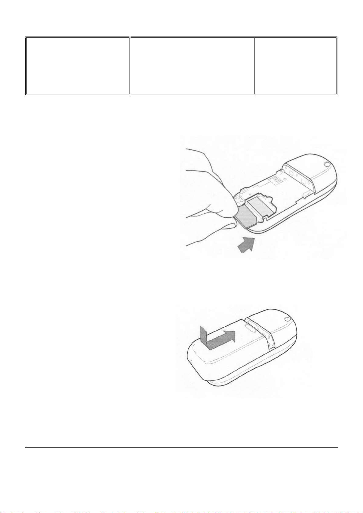
7.5 Inserting The Battery
Place the battery on the back of the phone
(battery c onnec tors downwards), then push it
into place until the latch catches
PHILIPS ELECTRONICS N.V. 1999 VY-V-640-82x
All rights reserved. Reproduction in whole
or in part is prohibited without the written
consent of the copyright owner.
Départ. Technic al s uppo rt- CM640 PROCEDURE COMPANY RESTRICTED
PHILIPS Con sumer
Communications
Centre du Mans
7.6 Removing The Battery
Press below the rubber (Philips logo)
and slide the batter y downwards
Service Repair Support
VY-V-640-82x
Page : 12 of 71
Langue : EN
Date : 25/02/03
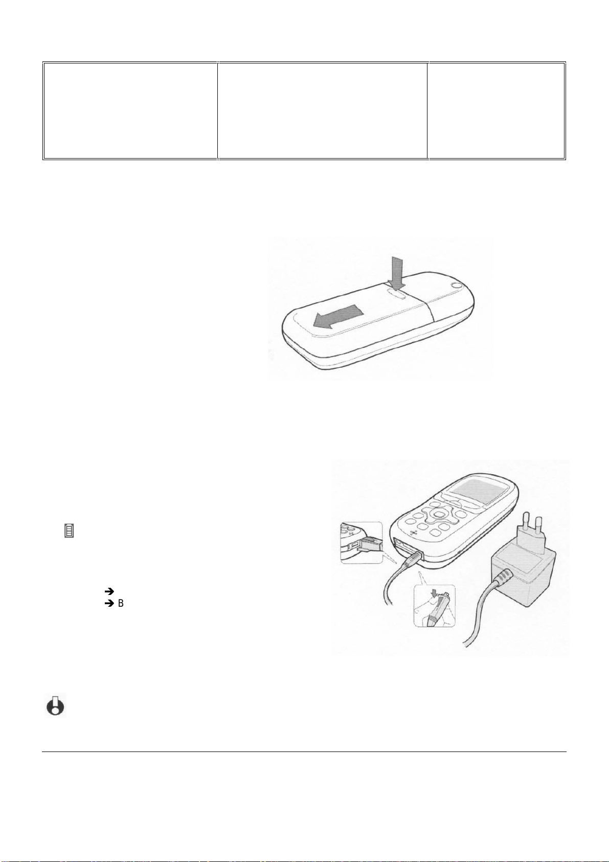
7.7 Charging The Battery
Once the battery i s clipped on the phone, plug the charger into the ri ght hand socket at the base of the phone as
shown on the drawing.
Then plug the transformer unit into a main AC power
socket with easy access.
The symbol indicates the state of char ge :
During charging the 4 charge indicators change; each bar
represents around 25% of charge.
Í
Bars moving
Bars steady
Battery outline flashing (see chapter 9)
When the battery is charged, remove the connector by
pressing the release button on top of the connector
If the battery is completely flat, the battery icon will only reappear after 2 or 3 minutes of char ging.
Battery is charging
Í
Battery is fully charged
PHILIPS ELECTRONICS N.V. 1999 VY-V-640-82x
All rights reserved. Reproduction in whole
or in part is prohibited without the written
consent of the copyright owner.

Départ. Technic al s uppo rt- CM640 PROCEDURE COMPANY RESTRICTED
PHILIPS Con sumer
Communications
Centre du Mans
Service Repair Support
VY-V-640-82x
Page : 13 of 71
Langue : EN
Date : 25/02/03
7.8 W@P Introduction
The purpose of W@p (Wirel ess Application Protocol) is to enable easy and fast delivery of relevant informati on and
services to m obile users. However, mobile Internet does not mean navigating on the Internet wit h a wireless devic e
but rather to access to some services in a mobile context.
The W@P architect ure was designed to enable standard Internet servers to provide servi ces to wireless dev ices.
The W@P wireless protocol is based on Internet standards such as HTTP and TLS but has been optimized
according to the c onstr aints of the wireless terminals: low memory capacity, small screen size
and of the network: limited bandwidth.
The W@P architect ur e is made up of 4 tec hnological parts which are necessary for accessing W@P services on a
mobile phone. These are:
W@P navigator or br owser
Mobile operator network
W@P gateway / W@P server
Web server
Customer Gateway Server
1.0 Encoded
Request
Encoder/
Decoder
4.0 Encoded
Answer
* Subscription
The customer has to contact his Network Operator to inquire about his subscription and the options he can
subscribe to. Generally the customer just have to request his W@P access to his provider and he will not be
charged for that.
PHILIPS ELECTRONICS N.V. 1999 VY-V-640-82x
All rights reserved. Reproduction in whole
or in part is prohibited without the written
consent of the copyright owner.
2.0 Request
Content
Generation
3.0 Answer

Départ. Technic al s uppo rt- CM640 PROCEDURE COMPANY RESTRICTED
PHILIPS Con sumer
Communications
Centre du Mans
Service Repair Support
VY-V-640-82x
Page : 14 of 71
Langue : EN
Date : 25/02/03
* W@P parameters
Parameters hav e to be set in t he m obile phone in order to access W@P services . Howev er, there ar e two
cases depending on the commercial offer:
* Transceiv er sold v ia an oper ator package
- Parameters cannot be ac c essed f r om the W@P settings menu of the mobile phone:
The transceiver is W@P locked. The W@P connections will always be made from the
operator W@P homepage and search engines will be available. The customer will have to
ask for a password fr om hi s/her oper ator to unlock the W@P settings.
- Parameters can be acc essed f r om the W@P settings menu of the mobile
phone:
The customer changes the W @P par am eters according to his/her own convenience.
* Retail transceiver
- Phones are configur ed by the manufacturer with no W@P parameter. The end user has
to ensure that the W@P f unctionality and a data/fax options hav e been subscribed.
The end user has also to set the W@P param eters by asking for them from
his/her operator or by usi ng par am eters of another company (available on
Internet, newspaper etc.)
(without subscription included):
(with subscription included):
Detailed parameters
Phone Number
(or User Name) : if requested by your IS P
Login
The password : if requested by your IS P
IP address for the Gateway : for communications between Inter net Service Provider and Gateway
& Port Number (for a secure or non secure connection)
Home page address
Please note that it is important to respect small and capital letters according to your oper ator instructions.
It is also possible that your provider does not require the Login and/or Password.
(or dial-up number) : to establish a connection with the Internet Service Provider
(or URL address): for communications between Gateway and Web server
PHILIPS ELECTRONICS N.V. 1999 VY-V-640-82x
All rights reserved. Reproduction in whole
or in part is prohibited without the written
consent of the copyright owner.

Départ. Technic al s uppo rt- CM640 PROCEDURE COMPANY RESTRICTED
PHILIPS Con sumer
Communications
Centre du Mans
Service Repair Support
VY-V-640-82x
Page : 15 of 71
Langue : EN
Date : 25/02/03
7.9 GPRS Introduction
7.9.1 Presentation
The GPRS does not constitute to him alone a separate mobile network, but a supplementary layer added to a
existing GSM network.
It can be thus settled without any supplementary license. This means that all the operators who have a GSM
license can develop their network towards it.
Furthermor e, the GPRS uses wavebands att ri buted to t he GSM. that means a band i n the 900 MHz , t he other one
in the 1800 MHz and finally the third for the USA, in the 1900 MHz
The GPRS, also called GSM 2+, rests on the transmission of data packets. This pri ncipl e, already hel d for exam ple
for the protocol X.25, allows to allocate to the other communic ations, t he time- outs of a first c ommunicati on (wait of
an answer to an Internet r equest for example).
Conceived to reuse at most the existing GSM infrastructures, the expansion of the GPRS requires the
implementation of a network infrastructure based on the data packets routi ng and the int r oduc tion of bridges to lean
on existing GSM networks.
This technol ogy, capabl e of supplying transf er rates rising up to 115 kb/s (against 9,6 kb/ s for the GSM), offers
interesting features:
• Several channels can be allocated to a single user;
• Several users can share a single c hannel;
• The transmission rate is independent from rising and downward links.
7.9.2 S ervices / Possibiliti es / Limitations
Domains of application
While the WAP stops in the consultation of the Internet pages, the GPRS allows to widen the servi ce offer . Besides
the access to Internet (or Intranet), from the traditional mobiles phones, it allows a better access to e-mails
containing joined files.
A rate higher than the wired public network
Today, the transmi ssion rate of a standard GSM network in "connect ed" mode does not overtake 9, 6 kbit/s, ev en
14,4 kbit/s by establi shment of specifi c software. It is five tim es less fast compared t o the standard wired network,
which authorises 56 kbit/s with a V90 modem.
PHILIPS ELECTRONICS N.V. 1999 VY-V-640-82x
All rights reserved. Reproduction in whole
or in part is prohibited without the written
consent of the copyright owner.

Départ. Technic al s uppo rt- CM640 PROCEDURE COMPANY RESTRICTED
PHILIPS Con sumer
Communications
Centre du Mans
Service Repair Support
VY-V-640-82x
Page : 16 of 71
Langue : EN
Date : 25/02/03
With the GPRS, a transmi ssion rate included between 40 and 115 kbit/ s is availabl e. Everything depends on the
number of virtual canals or " time slots " used, and on coding scheme (CS1 to CS4). GPRS acts on the
compression of t he data as a multiplier of transmission rat e. In 3+1 multislots mode (three slots for the network
towards mobil e, and one slot for the mobile towards network), it allows a transmi ssion rate of 40 k bit/s with a CS2
coding scheme.
With (8+1)multi sl ots using the CS4 coding scheme, one achieves i n pr actic e 115 k bit/s (in theory 175 kbit/s).
GPRS re-uses the exi sting GSM infrastr ucture, notably by keeping the current network of base stat ions ( BTS),
upgrading the BTS software.
Average time t o send an E-m ail with a 10 pages attached document :
Standard Rate Time elapsed
Current GSM 9,6 kbit/s 7 min.
Standard Modems (V90) 57,6 kbit/s 70 sec.
RNIS 128 kbit/s 31 sec.
GPRS 144 bit/s * 28 sec.
EDGE 384 kbit/ s * 10 sec.
UMTS 2 Mbit/s 2 sec.
* : in optimal conditions
Three types of air terminals
Three types of air terminals were defined to meet the needs of the GPRS: the basic model (cl ass B) is foreseen for
the voice and the data i n not simultaneous m ode. The prof essional or industri al model (cl ass C) i s dat a exclusi v ely
(the air termi nal is used as a m odem ). Finally the up-market (class A ) is compati ble voice/data simultaneously. This
class A terminal is problematic. The power of calculation required at the moment has a strong incidence on its
production cost and makes it dissuasive.
In the GPRS standard, thr ee new types of mobile terminal have been defined:
Class A terminal, which support s simultaneous cir c uit-switched and packed-switched t r aff ic;
Class B terminal, which supports either circuit-switched or packed-switched traffic (simultaneous network
attachment) but does not support both kinds of traffic simultaneously;
Class C terminal, whic h is attached either as a packed-switched or c ir c uit-switched terminal.
The terminal types are further differentiated by their ability to handle multislot operations. The terminal can use
from 1 up to 8 time slots on the uplink and on t he downlink channel . 18 service classes are defi ned depending on
the number for support time slots.
PHILIPS ELECTRONICS N.V. 1999 VY-V-640-82x
All rights reserved. Reproduction in whole
or in part is prohibited without the written
consent of the copyright owner.

Départ. Technic al s uppo rt- CM640 PROCEDURE COMPANY RESTRICTED
PHILIPS Con sumer
Communications
Centre du Mans
Service Repair Support
Servic
e Class
1 112 1
2 213 1
3 223 1
4 314 1
5 224 1
6 324 1
7 334 1
8 415 1
9 325 1
10 425 1
11 435 1
12 445 1
13 336 2
14 448 2
15 5510 2
16 6612 2
17 7714 2
18 8816 2
Max Number of Slots
MaxRxMaxTxTotal
available
Multislot
type
Fig. 1 Service Classes - Multislot operations
VY-V-640-82x
Page : 17 of 71
Langue : EN
Date : 25/02/03
Four different channel-coding schemes have been defined for GPRS to make optimum use of varying radio
conditions. Usage of higher coding schemes all ows to send mor e data in the same number of time slots.
Channel Coding
CS-1 CS-2 CS-3 CS-4
Scheme
Data rate per
9.05 13.4 15.6 21.4
timeslot (kbps)
Fig. 2 GPRS Coding Schemes
Philips Fisio820 features GP RS Class B. With GPRS Class B, if you receiv e incoming call s whil e in the middle of a
data session, you receive a notification; and v ic e versa.
Philips Fisio820 is enabled to support GPRS up to Class10 (4Rx, 2Tx) [depending on networks developments].
GPRS Class10 enables to rec eiv e information at l east 4 times faster t han a standard G SM connection and to send
them 2 times faster. That is why GPRS Class 10 is particul arly suitable f or surfing on the WAP pages, exchangi ng
emails or using y our phone as a modem for Int er net surfing, Intranet br owsing or fi le transfer.
Philips Fisi o820 is SMG31bis - Coding schemes 1, 2, 3 et 4.
PHILIPS ELECTRONICS N.V. 1999 VY-V-640-82x
All rights reserved. Reproduction in whole
or in part is prohibited without the written
consent of the copyright owner.

Départ. Technic al s uppo rt- CM640 PROCEDURE COMPANY RESTRICTED
PHILIPS Con sumer
Communications
Centre du Mans
Service Repair Support
VY-V-640-82x
Page : 18 of 71
Langue : EN
Date : 25/02/03
7.9.3 Technical characteristics
Circuit switched mode or virtual access
The first advant age of the GPRS is to allow a better use of the radio and technic al resources. While the GSM works
in "connected" mode, called also "circuit-switched" mode, the GPRS uses f or its part the virtual connection m ode.
In "virtual" mode, the resources are shared. The transmission channel is never allocated to a unique user, but
shared between sev eral users. Every user has it when he needs it and only in that case. The r est of the time they
are availabl e. The circ uit switched mode cor responds to t he f uncti oning of a GSM li ne or still a standard t elephone
line. It consists in establishing a physical link between two points or two correspondents. Once the number is
dialled, a circ uit is permanent ly all ocated to the comm unicati on, wit hout any sharing wit h the other c ustomers. T his
mode of functioning which does not take into account periods of silence, when no data is passed on, does not
optimise at its best t he r adio resources.
The GPRS puts in evidenc e the more important role of t he network administrat or. In a GSM infrastruc ture t he role
of the administ r ator amounts to affect physical resources at t he beginning of every c ommunication. With the GPRS,
its role is more im portant. It consists i n assigning, in real time, t he physical resources (memories and electroni c
circuit s), in m anaging the radio resources, and in affecting them according to the demand.
The GPRS settles down on the existing GSM network
The GPRS-system is built upon the existing GSM-infrastructure. Basic stations undergo no modification with
exception of the specific software, that can be installed by downloading.
Next, the Basic Stati ons Controller (BSC) should be doubl ed by a Packet Cont r oller Unit (PCU).
Then comes the path int ended for data packets, its composed of :
- The Serving GPRS Specific Node (SGSN) , equivalent of the Mobile Switch Controller ( MSC), which aims to
check subscribers register ing , to authenti cate them and to authorise the communications,
- The Access module (GGSN) to t he IP worl d (I nternet or Intranet).
GGSN and SGSN are described later.
PHILIPS ELECTRONICS N.V. 1999 VY-V-640-82x
All rights reserved. Reproduction in whole
or in part is prohibited without the written
consent of the copyright owner.
Départ. Technic al s uppo rt- CM640 PROCEDURE COMPANY RESTRICTED
PHILIPS Con sumer
Communications
Centre du Mans
7.9.4 Network Architecture
BTS
(Base Stations)
BSC
(Base Stations
Controller)
PCU
(Packets Control
Unit)
Service Repair Support
GMSC
Circuit-switched traffic mode
(voice)
MSC
SGSN
(GPRS Specific
Switch)
Packe t s traffic
(data)
GGSN
(IP access Module)
VY-V-640-82x
Page : 19 of 71
Langue : EN
Date : 25/02/03
RTC
GPRS
Register
H/VL R
PUBLIC INTERNET
NETWORK
GPRS network archit ec ture
The constituents of the GPRS network
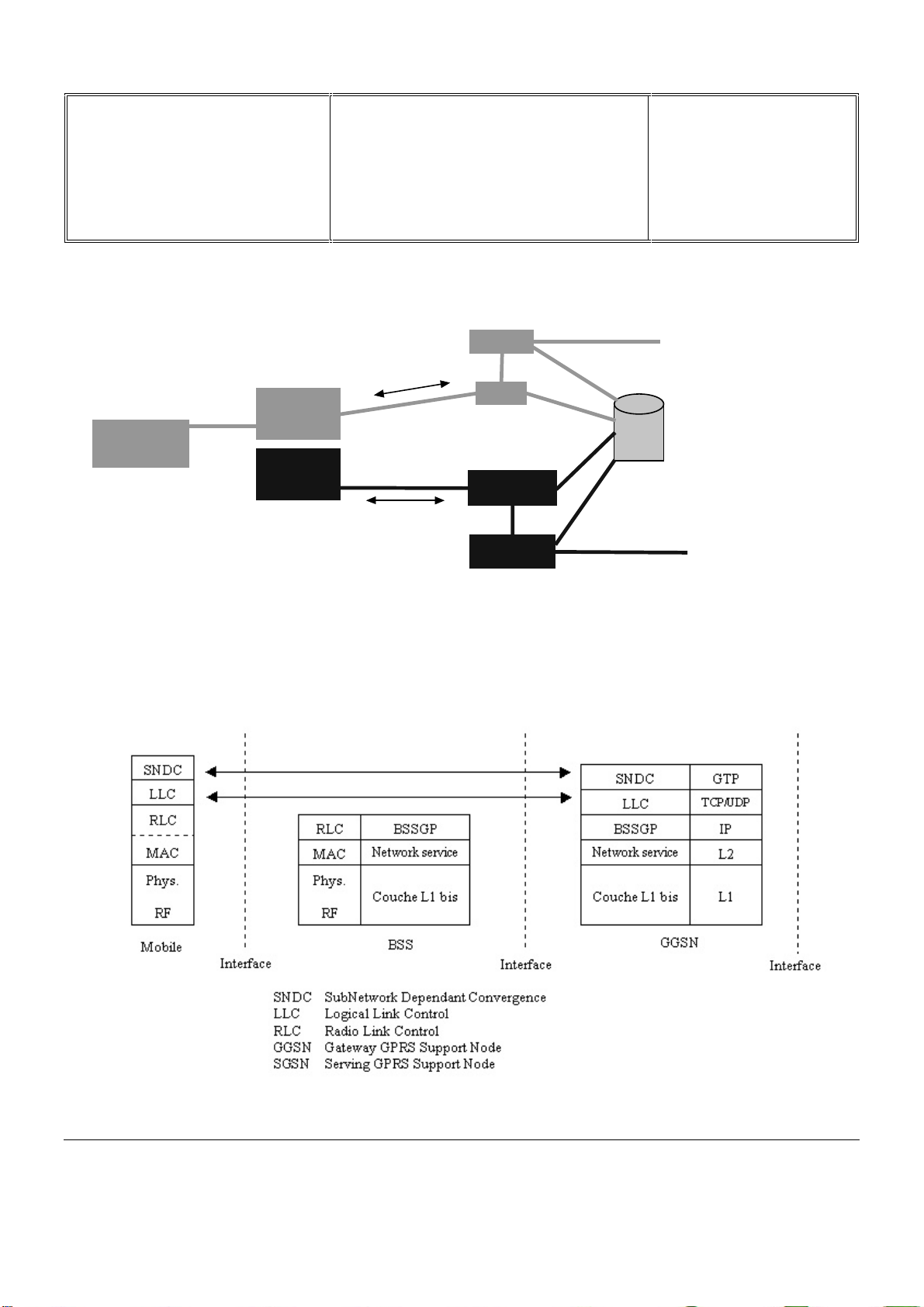
There is the soft ware l ay er s architecture for every consti tuent of a GPRS network.
Software layers of a GPRS network
PHILIPS ELECTRONICS N.V. 1999 VY-V-640-82x
All rights reserved. Reproduction in whole
or in part is prohibited without the written
consent of the copyright owner.

Départ. Technic al s uppo rt- CM640 PROCEDURE COMPANY RESTRICTED
PHILIPS Con sumer
Communications
Centre du Mans
Service Repair Support
VY-V-640-82x
Page : 20 of 71
Langue : EN
Date : 25/02/03
In the mobile terminal, appears from the bottom to the top the following layers :
n
The physical layer, constituted of two functional sub-layers;
• The RF sub-layer, whic h m anage the radio operations of the terminal. It emits the data received fr om
the physical lay er. It dec odes the data coming from the base station (BTS) and transmits it to the
physical layer for inte r p r etation
• The physical layer produces the frames, those ones will be emi tt ed by the RF layer; about the frames
received from the network, it detects and corrects tr ansmission errors.
n
The MAC layer (or RLC for Radio Link Control) manages the radi o link between the terminal and the Base
Station (BTS) , t hat means re-em ission mechanisms in case of err or , the function of access controll er for
the radio resources when several air terminals are i n competition. The RLC can request the re- emi ssion of
a data packet ;
n
The higher layer SNDC (Sub-Network Dependant Conv er genc e) manages the mobility, t he ci pheri ng and
data compression.
GGSN : Gateway GPRS Support Node ,
The GGSN provides the int erface towards the external IP packet net works. Ac tually, from the external IP network’s
point of view, the GGS N acts as a router for the IP-addresses of all subscribers served by the GPRS-networks. T o
make this possible the GGSN exchanges routing information with the external net works and sets up connections
towards external networks. Similar to the SGSN, t he GGSN deals with session management, specifically the
connection t owards the external networks. Al so, as many SGS N can connect to one GGSN, it has to associate
subscribers to the r ight SGSN.
SGSN : Serving GPRS Support Node
The SGSN forwards incoming and outgoing IP packets addressed to and f r om a mobile station. It serves all GPRS-
subscribers that ar e located and attached within the geographic SGSN service area.. A subscriber may be served
by any SGSN in the GPRS network depending on location. The traffic is rooted from the SGSN to the BSC, via the
BTS to the mobile stati on. To make this packet traffic possible, signalling with several other nodes is necessary, for
instance the Home Location Register (HLR) , the Mobil e Switc hing Centre (MSC), the BSC and the GGSN, as well
Short Message Service-nodes (SMS). From these signalling connections the SGS N handles important GPRS
functions such as cipher ing and authentication, session management, mobility management and the logical link
management towards the mobile station.
Packets routing
The routing of ev er y packet is independent from the one who precedes it or by t he one who follows it. During the
connection phase of a GSM termi nal in a network, the signalling exc hanges are multiple, and to face the
constraints of the packet mode, the informati on of routing obtained to forward the first pac k et to a GSM terminal is
stored in the GGSN. So, the routing of following packets i s selec ted according the context stored in the GGSN ( the
Temporary Logical Link Identity or TLLI).
PHILIPS ELECTRONICS N.V. 1999 VY-V-640-82x
All rights reserved. Reproduction in whole
or in part is prohibited without the written
consent of the copyright owner.
Départ. Technic al s uppo rt- CM640 PROCEDURE COMPANY RESTRICTED
PHILIPS Con sumer
Communications
Centre du Mans
Service Repair Support
VY-V-640-82x
Page : 21 of 71
Langue : EN
Date : 25/02/03
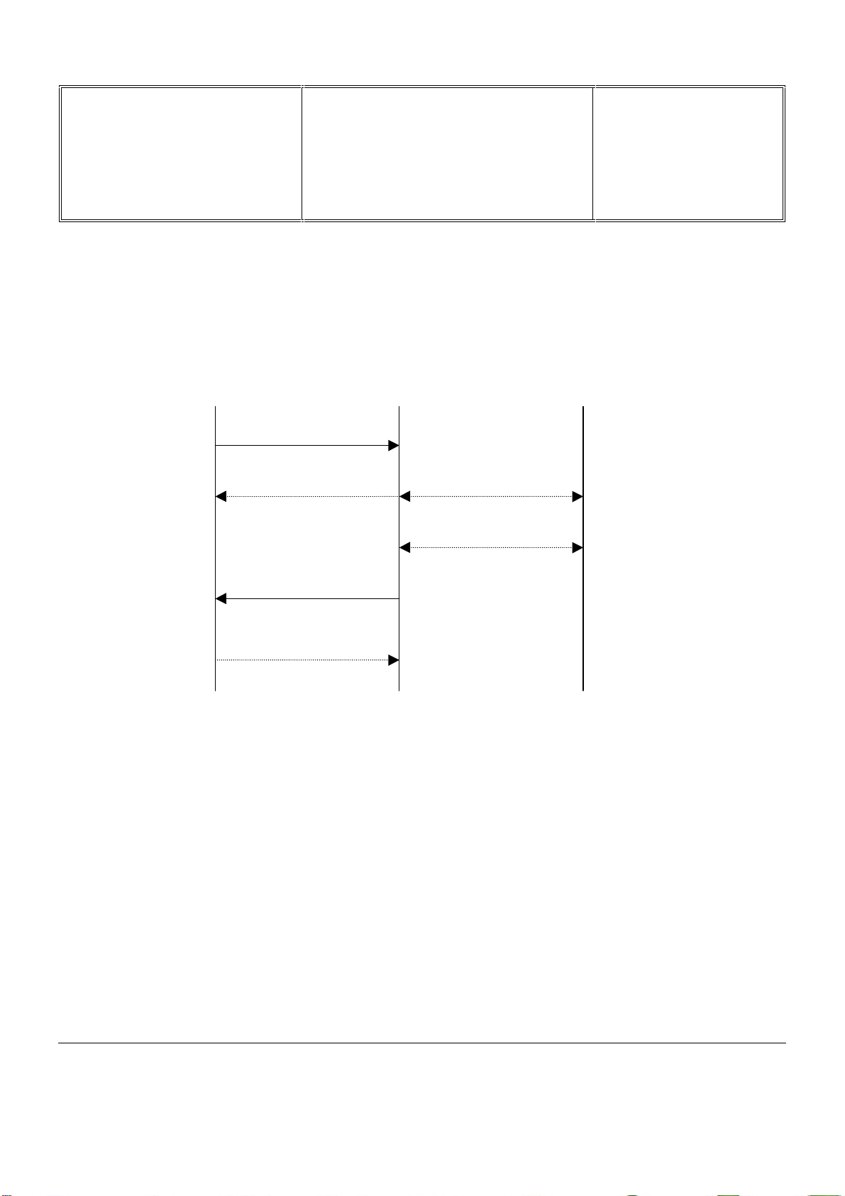
7.9.5 GPRS Attach and GPRS Detach procedur es
The procedure for a GPRS attach is made by the MS to the SGSN. After Havi ng executed a successful GPRS
attach, mobility management contexts are establi shed in the MS and the SGSN, setting the MS in the READY
state. The MS is then abl e to activate PDP-contexts. The procedur e of GPRS attach is illustrated below.
MS SGSN HLR
1. Attach Request
2. Authentication
3. Location Update
4. Attach Accept
Response
5. Attach Complete
GPRS attach procedure
1. The MS sends a GPRS attach request which includes the GPRS mobile cl ass and the multislot class.
2. Authentication is carried out in the same manner as with GSM, but instead of the MSC, it’s the SGSN that
sends the IMSI of the MS to the HLR, initiating the encryption al gori thm.
3. A location update procedur e stor es the c ur r ent SGSN of the MS in the HLR.
4. The attach accept response as si gns a Temporary Logical Link Ident ity (TLLI) to the MS.
5. A GPRS attach complete response from the MS to the SGSN confirms the attach.
After the authentication within the GPRS att ac h procedure, no additional authentication is r equired during the entire
GPRS-session. A GPRS detach will terminate the ongoing GPRS-session. This detach could be initi ated explicitly
by the MS or the SGSN, or implicitly when the STANDBY-timer runs out.
PHILIPS ELECTRONICS N.V. 1999 VY-V-640-82x
All rights reserved. Reproduction in whole
or in part is prohibited without the written
consent of the copyright owner.

Départ. Technic al s uppo rt- CM640 PROCEDURE COMPANY RESTRICTED
PHILIPS Con sumer
Communications
Centre du Mans
Service Repair Support
VY-V-640-82x
Page : 22 of 71
Langue : EN
Date : 25/02/03
7.10 BLUETOOTH Introduction
7.10.1 Presentation
The Bluetooth t echnology eliminates the need f or wires, c ables and the corresponding connect or s betwee n
cordless or mobile phones, modems, headsets, PDAs, computers, printers, projec tors, and so on and paves the
way for new and complet ely diff er ent devices and applications.
The majority of radio systems in commercial use today are based on a cell ular radio Architectur e. A mobil e network
established on a wired backbone infrastructur e uses one or more base stations placed at str ategic positions to
provide local cell coverage; users apply portable phones, or more generic mobile terminals, to access the mobile
network; the terminals maintain a connection to the network via a radio link to the base stations. There is a strict
separation between t he base stations and the terminals. Once registered to the network, the terminals remain
locked to the control c hannels in the network, and connections can be established and released according to the
control channel pr otocols. Channel access, channel allocation, traffic c ontrol, and interference mi nimi z ation are
neatly controlled by the base stations.
PHILIPS ELECTRONICS N.V. 1999 VY-V-640-82x
All rights reserved. Reproduction in whole
or in part is prohibited without the written
consent of the copyright owner.
 Loading...