


32BDL3110Q
43BDL3110Q
50BDL3110Q
55BDL3110Q
65BDL3110Q
V1.00
www.philips.com/welcome
User Manual (English)

Safety Instructions
Safety precautions and maintenance
WARNING: Use of controls, adjustments or procedures other than those specied in this documentation may result in exposure to
shock, electrical hazards and/or mechanical hazards.
Read and follow these instructions when connecting and using your display:
Operation:
• Keep the display out of direct sunlight and away from stoves or any other heat sources.
• Remove any object that could fall into ventilation holes or prevent proper cooling of the display’s electronics.
• Do not block the ventilation holes on the cabinet.
• When positioning the display, make sure the power plug and outlet are easily accessible.
• When turning off the display by detaching the power cord, wait 6 seconds before re-attaching the power cord for normal operation.
• Ensure the use of an approved power cord provided by Philips at all times. If your power cord is missing, please contact your local service center.
• Do not subject the display to severe vibration or high impact conditions during operation.
• Do not knock or drop the display during operation or transportation.
• The eye bolt is for usage in short-time maintenance and installation. We suggest not to use the eye bolt for more than 1 hour. Prolong usage is
prohibited. Please keep a clear safety area under the display while using the eye bolt.
Maintenance:
• To protect your display from possible damage, do not put excessive pressure on the LCD panel. When moving your display, grasp the frame to lift; do
not lift the display by placing your hand or ngers on the LCD panel.
• Unplug the display if you are not going to use it for an extensive period of time.
• Unplug the display if you need to clean it with a slightly damp cloth. The screen may be wiped with a dry cloth when the power is off. However, never
use organic solvent, such as, alcohol, or ammonia-based liquids to clean your display.
• To avoid the risk of shock or permanent damage to the set, do not expose the display to dust, rain, water or an excessively moist environment.
• If your display becomes wet, wipe it with dry cloth as soon as possible.
• If a foreign substance or water gets in your display, turn the power off immediately and disconnect the power cord. Then remove the foreign substance
or water, and send the unit to the maintenance center.
• Do not store or use the display in locations exposed to heat, direct sunlight or extreme cold.
• In order to maintain the best performance of your display and ensure a longer lifetime, we strongly recommend using the display in a location that falls
within the following temperature and humidity ranges.
- Temperature: 0-40°C 32-104°F
- Humidity: 20-80% RH
• LCD panel temperature need to be 25 degrees Celsius at all time for better luminance performance.
IMPORTANT: Always activate a moving screen saver program when you leave your display unattended. Always activate a periodic screen refresh
application if the unit will display unchanging static content. Uninterrupted display of still or static images over an extended period may cause “burn in”,
also known as “after-imaging” or “ghost imaging”, on your screen. This is a well-known phenomenon in LCD panel technology. In most cases, the “burned
in” or “after-imaging” or “ghost imaging” will disappear gradually over a period of time after the power has been switched off.
WARNING: Severe “burn-in” or “after-image” or “ghost image” symptoms will not disappear and cannot be repaired. This is also not covered under the
terms of your warranty.
Service:
• The casing cover should be opened only by qualied service personnel.
• If there is any need for repair or integration, please contact your local service center.
• Do not leave your display under direct sunlight.
If your display does not operate normally, having followed the instructions set out in this document, please contact a technician or your
local service center.
ii

Read and follow these instructions when connecting and using your display:
• Unplug the display if you are not going to use it for an extensive period of time.
• Unplug the display if you need to clean it with a slightly damp cloth. The screen many be wiped with a dry cloth when the power is
off. However, never use alcohol, solvents or ammonia-based liquids.
• Consult a service technician if the display does not operate normally when you have followed the instructions in this manual.
• The casing cover should be opened only by qualied service personnel.
• Keep the display out of direct sunlight and away from stoves or any other heat sources.
• Remove any object that could fall into the vents or prevent proper cooling of the display’s electronics.
• Do not block the ventilation holes on the cabinet.
• Keep the display dry. To avoid electric shock, do not expose it to rain or excessive moisture.
• When turning off the display by detaching the power cable or DC power cord, wait for 6 seconds before re-attaching the power
cable or DC power cord for normal operation..
• To avoid the risk of shock or permanent damage to the set do not expose the display to rain or excessive moisture.
• When positioning the display, make sure the power plug and outlet are easily accessible.
• IMPORTANT: Always activate a screen saver program during your application. If a still image in high contrast remains on the
screen for an extended period of time, it may leave an ‘after-image’ or ‘ghost image’ on the front of the screen. This is a well-known
phenomenon that is caused by the shortcomings inherent in LCD technology. In most cases the afterimage will disappear gradually
over a period of time after the power has been switched off. Be aware that the after-image symptom cannot be repaired and is not
covered under warranty.
iii
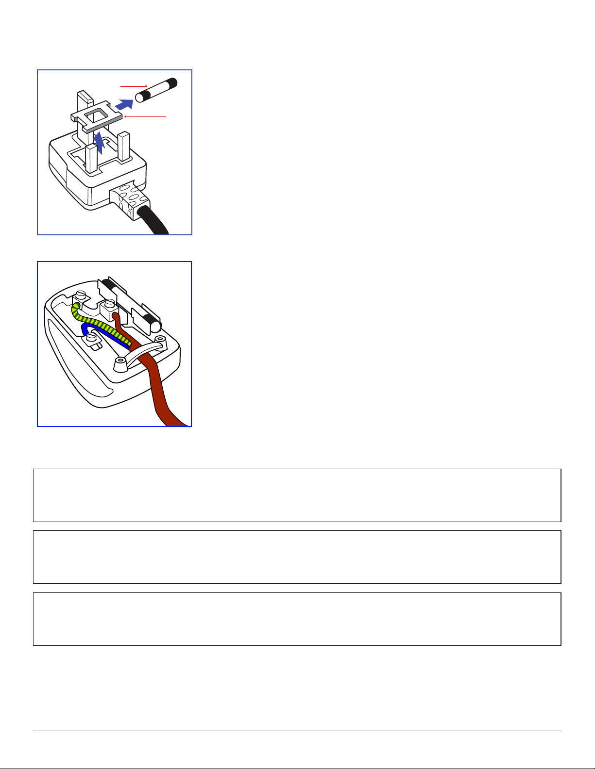
Information for U.K. only
(B)
(A)
WARNING - THIS APPLIANCE MUST BE EARTHED.
Important:
This apparatus is supplied with an approved moulded 13A plug. To change a fuse in this type of plug
proceed as follows:+
1. Remove fuse cover and fuse.
2. Fit new fuse which should be a BS 1362 5A,A.S.T.A. or BSI approved type.
3. Ret the fuse cover.
If the tted plug is not suitable for your socket outlets, it should be cut off and an appropriate 3-pin
plug tted in its place.
If the mains plug contains a fuse, this should have a value of 5A. If a plug without a fuse is used, the fuse
at the distribution board should not be greater than 5A.
NOTE: The severed plug must be destroyed to avoid a possible shock hazard should it be inserted
into a 13A socket elsewhere.
How to connect a plug
The wires in the mains lead are coloured in accordance with the following code:
BLUE - “NEUTRAL” (“N”)
BROWN - “LIVE” (“L”)
GREEN & YELLOW - “EARTH” (“E”)
1. The GREEN & YELLOW wire must be connected to the terminal in the plug which is marked with
the letter “E” or by the Earth symbol or coloured GREEN or GREEN & YELLOW.
2. The BLUE wire must be connected to the terminal which is marked with the letter “N” or coloured
BLACK.
3. The BROWN wire must be connected to the terminal which marked with the letter “L” or
coloured RED.
Before replacing the plug cover, make certain that the cord grip is clamped over the sheath of the lead
- not simply over the three wires.
North Europe (Nordic Countries) Information
Placering/Ventilation
VARNING:
FÖRSÄKRA DIG OM ATT HUVUDBRYTARE OCH UTTAG ÄR LÄTÅTKOMLIGA, NÄR DU STÄLLER DIN UTRUSTNING PÅPLATS.
Placering/Ventilation
ADVARSEL:
SØRG VED PLACERINGEN FOR, AT NETLEDNINGENS STIK OG STIKKONTAKT ER NEMT TILGÆNGELIGE.
Paikka/Ilmankierto
VAROITUS:
SIJOITA LAITE SITEN, ETTÄ VERKKOJOHTO VOIDAAN TARVITTAESSA HELPOSTI IRROTTAA PISTORASIASTA.
iv
Plassering/Ventilasjon
ADVARSEL:
NÅR DETTE UTSTYRET PLASSERES, MÅ DU PASSE PÅ AT KONTAKTENE FOR STØMTILFØRSEL ER LETTE Å NÅ.
End-of-Life Disposal
Your new Public Information Display contains materials that can be recycled and reused. Specialized companies can recycle your product to increase the
amount of reusable materials and to minimize the amount to be disposed of.
Please nd out about the local regulations on how to dispose of your old display from your local Philips dealer.
(For customers in Canada and U.S.A.)
This product may contain lead and/or mercury. Dispose of in accordance to local-state and federal regulations. For additional information on recycling
contact www.eia.org (Consumer Education Initiative)
Waste Electrical and Electronic Equipment-WEEE
Attention users in European Union private households
This marking on the product or on its packaging illustrates that, under European Directive 2012/19/EU governing used electrical and
electronic appliances, this product may not be disposed of with normal household waste. You are responsible for disposal of this
equipment through a designated waste electrical and electronic equipment collection. To determine the locations for dropping off such
waste electrical and electronic, contact your local government ofce, the waste disposal organization that ser ves your household or the
store at which you purchased the product.
Attention users in United States:
Please dispose of according to all Local, State and Federal Laws. For the disposal or recycling information, contact: www.mygreenelectronics.com or www.
eiae.org.
End of Life Directives-Recycling
Your new Public Information Display contains several materials that can be recycled for new users.
Please dispose of according to all Local, State, and Federal laws.
Restriction on Hazardous Substances statement (India)
This product complies with the “E-Waste (Management) Rules, 2016” CHAPTER V, rule 16, sub-rule (1) . Whereas New Electrical and Electronic
Equipment and their components or consumables or parts or spares do not contain Lead, Mercury, Cadmium, Hexavalent Chromium, polybrominated
biphenyls and polybrominated diphenyl ethers beyond a maximum concentration value of 0.1% by weight in homogenous materials for lead, mercury,
hexavalent chromium, polybrominated biphenyls and polybrominated diphenyl ethers and of 0.01% by weight in homogenous materials for cadmium.
except of exemptions set in Schedule 2 of the Rule.
E-Waste Declaration for India
This symbol on the product or on its packaging indicates that this product must not be disposed of with your other household waste.
Instead it is your responsibility to dispose of your waste equipment by handing it over to a designated collection point for the recycling
of waste electrical and electronic equipment . The separate collection and recycling of your waste equipment at the time of disposal
will help to conserve natural resources and ensure that it is recycled in a manner that protects human health and the environment.
For more information about E -waste please visit http://www.india.philips.com/about/sustainability/recycling/index.page and to know
where you can drop off your waste equipment for recycling in India please contact on below given contact details.
Helpline number: 1800-425-6396 (Monday to Saturday, 9 a.m. to 5:30 pm)
E-mail: india.callcentre@tpv-tech.com
v
Batteries
Após o uso, as pilhas
deverão ser entregues ao
estabelecimento comercial
ou
e/ou baterias
rede de assistência técnica
autorizada.
For EU: The crossed-out wheeled bin implies that used batteries should not be put to the general household waste! There is a separate
collection system for used batteries, to allow proper treatment and recycling in accordance with legislation.
Please contact your local authority for details on the collection and recycling schemes.
For Switzerland: The used battery is to be returned to the selling point.
For other non-EU countries: Please contact your local authority for correct method of disposal of the used battery.
According to EU directive 2006/66/EC, the battery can’t be disposed improperly. The battery shall be separated
to collect by local service.
vi

Table Of Contents
1. Unpacking and Installation .......................................................1
1.1. Unpacking ......................................................................................... 1
1.2. Package Contents ........................................................................1
1.3. Installation Notes .........................................................................1
1.4. Mounting on a Wall ....................................................................2
2. Parts and Functions ...................................................................4
2.1. Control Panel .................................................................................4
2.2. Input/Output Ter minals .............................................................5
2.3. Remote Control ...........................................................................7
3. Connecting External Equipment.............................................8
3.1. Connecting External Equipment (DVD/VCR/VCD) 8
3.2. Connecting a PC ..........................................................................8
3.3. Connecting Audio Equipment .............................................. 9
3.4. Connecting USB ...........................................................................9
4. Operation ................................................................................. 10
4.1. Overview.......................................................................................10
4.2. Media Player introduction: ................................................... 10
4.3. PDF reader play ......................................................................... 12
4.4. Application page ........................................................................14
4.5. Setting page .................................................................................. 14
4.6. Using CMS 3.1 ............................................................................ 16
5. OSD Menu ............................................................................... 17
5.1. Navigating the OSD Menu ................................................17
5.2. OSD Menu Overview ........................................................... 18
6. Compatibility of the USB device ......................................... 20
7. Input mode ............................................................................... 22
8. Cleaning and Troubleshooting .............................................. 24
8.1. Cleaning ..........................................................................................24
8.2. Troubleshooting ......................................................................... 25
9. Technical Specications ......................................................... 26
vii
1. Unpacking and Installation
1.1. Unpacking
• This product is packed in a carton, together with the standard accessories.
• Any other optional accessories will be packed separately.
• Due to the size and weight of this display it is recommended for two people to move it.
• After opening the carton, ensure that the contents are complete and in good condition.
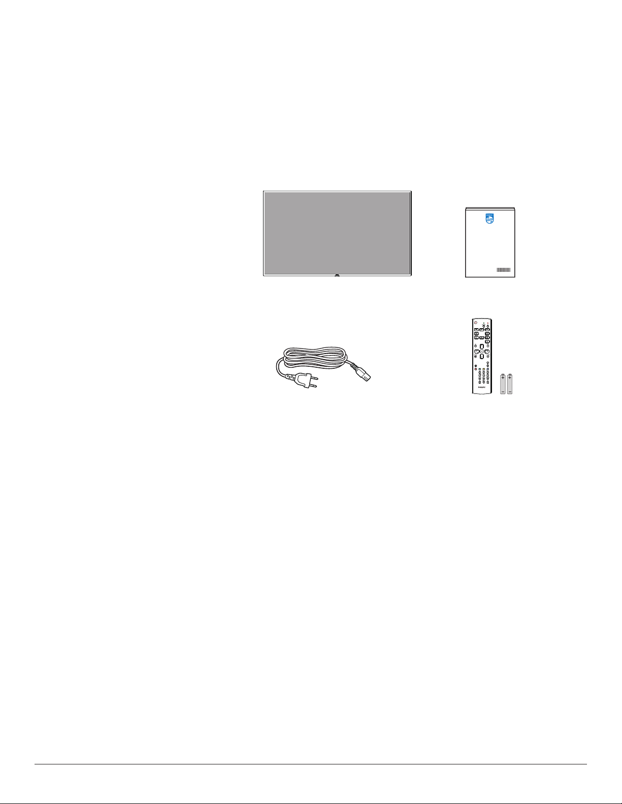
1.2. Package Contents
Please verify that you received the following items with your package content:
• LCD display
• Quick start guide
• Remote control with AAA batteries
• Power cord
* The supplied power cord varies depending on destination.
* Differences according to regions
Display design and accessories may differ from those illustrated above.
NOTES:
• For all other regions, apply a power cord that conforms to the AC voltage of the power socket and has been approved by and complies with the
safety regulations of the particular country (Type H05W-F, 2G or 3G, 0.75 or 1 mm2 should be used).
• You might like to save the package box and packing material for shipping the display.
Quick start guide
Remote Control Power Cord
and AAA Batteries
1.3. Installation Notes
• Due to the high power consumption, always use the plug exclusively designed for this product. If an extended line is required, please consult your
service agent.
• The product should be installed on a at surface to avoid tipping. The distance between the back of the product and the wall should be maintained
for proper ventilation. Avoid installing the product in the kitchen, bathroom or any other places with high humidity so as not to shorten the service life
of the electronic components.
• The product can normally operate only under 3000m in altitude. In installations at altitudes above 3000m, some abnormalities may be experienced.
1

1.4. Mounting on a Wall
To mount this display to a wall, you will have to obtain a standard wall-mounting kit (commercially available). We recommend using a mounting interface
that complies with TUV-GS and/or UL1678 standard in North America.
32BDL3110Q 43BDL3110Q
Protective Sheet
Protective Sheet
VESA Grid
Table
VESA Grid
Table
50BDL3110Q/55BDL3110Q/65BDL3110Q
Protective Sheet
VESA Grid
Table
1. Lay a protective sheet on a table, which was wrapped around the display when it was packaged, beneath the screen surface so as not to scratch the
screen face.
2. Ensure you have all accessories for mounting this display (wall mount, ceiling mount, table stand, etc).
3. Follow the instructions that come with the base mounting kit. Failure to follow correct mounting procedures could result in damage to the equipment
or injury to the user or installer. Product warranty does not cover damage caused by improper installation.
4. For the wall-mounting kit, use M6 mounting screws (having a length 10 mm longer than the thickness of the mounting bracket) and tighten them
securely. (Please use M4 screws for 32BDL3110Q.)
5. The equipment and its associated mounting means still remain secure during the test. For use only with UL Listed Wall Mount Bracket with minimum
weight/load of the weight of the unit.
1.4.1. VESA Grid
32BDL3110Q 100(H) x 100(V) mm
43BDL3110Q 200(H) x 200(V) mm
50BDL3110Q 200(H) x 200(V) mm
55BDL3110Q 200(H) x 200(V) mm
65BDL3110Q 300(H) x 200(V) mm
1.4.2. Weight of the unit
32BDL3110Q 5.1 kg
43BDL3110Q 8.4 kg
50BDL3110Q 12.0 kg
55BDL3110Q 14.0 kg
65BDL3110Q 21.0 kg
2
Caution:
To prevent the display from falling:
• For wall or ceiling installation, we recommend installing the display with metal brackets which are commercially available. For detailed installation
instructions, refer to the guide received with the respective bracket.
• To lessen the probability of injury and damage resulting from fall of the display in case of earthquake or other natural disaster, be sure to consult the
bracket manufacturer for installation location.
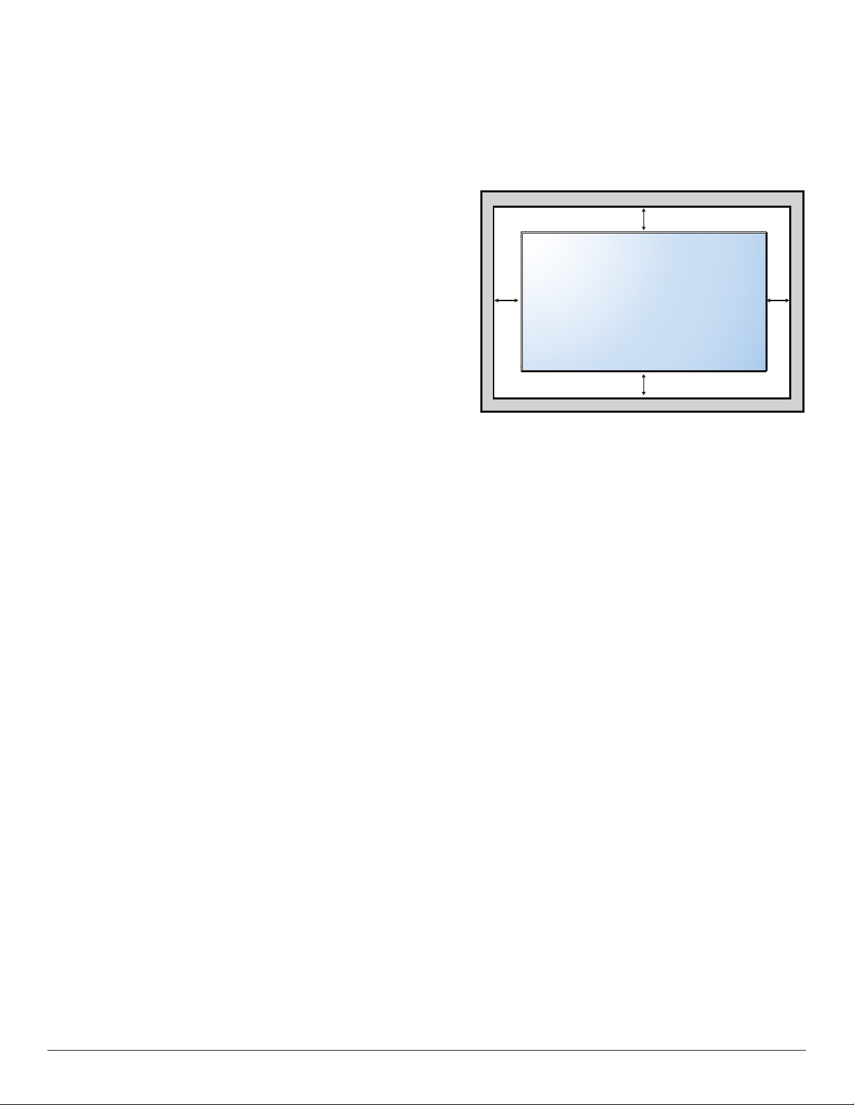
Ventilation Requirements for enclosure locating
To allow heat to disperse, leave space between surrounding objects as shown in the
diagram below.
100 mm
100 mm 100 mm
100 mm
3
2. Parts and Functions
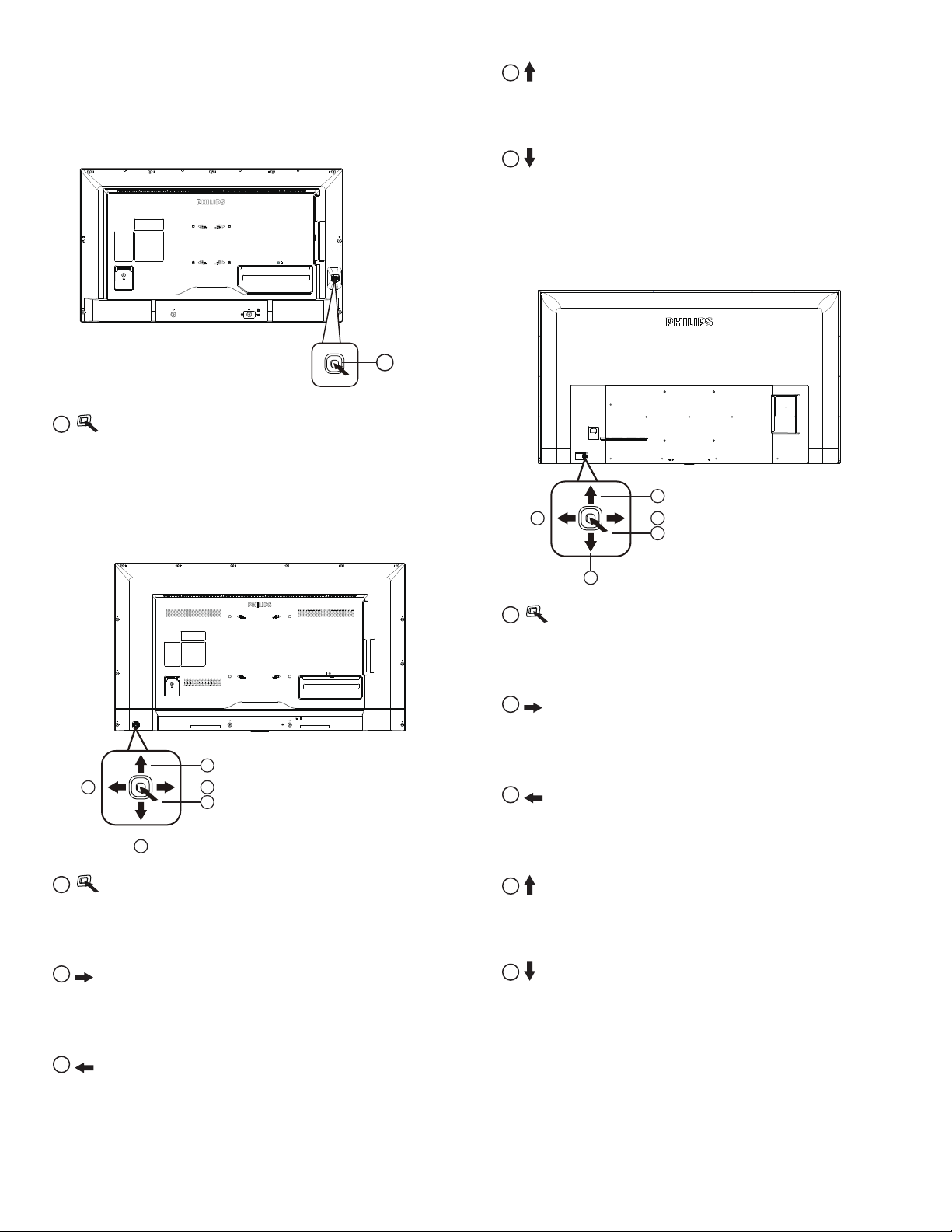
2.1. Control Panel
32BDL3110Q
1
• Press to switch power on.
• Press more than 5 seconds to switch power off.
• Conrm the OSD adjustment.
43BDL3110Q
4
• Android interface: move up.
• Main Menu: move the highlight bar up to adjust the selected
item while OSD menu is on
5
• Android interface: move down.
• Main Menu: move the highlight bar down to adjust the selected
item while OSD menu is on.
50BDL3110Q/55BDL3110Q/65BDL3110Q
1
4
2
3
1
4
2
5
1
3
1
• Press to switch power on.
• Press more than 5 seconds to switch power off.
• Conrm the OSD adjustment.
2
• Increase the volume.
• Android interface: move to the right.
• Main Menu: enter into submenu while OSD menu is on.
5
1
• Press to switch power on.
• Press more than 5 seconds to switch power off.
• Conrm the OSD adjustment.
2
• Increase the volume.
• Android interface: move to the right.
• Main Menu: enter into submenu while OSD menu is on.
3
• Decrease the volume
• Android interface: move to the left.
• Main Menu: back to previous menu while OSD menu is on
4
• Android interface: move up.
• Main Menu: move the highlight bar up to adjust the selected
item while OSD menu is on
5
• Android interface: move down.
• Main Menu: move the highlight bar down to adjust the selected
item while OSD menu is on.
3
• Decrease the volume
• Android interface: move to the left.
• Main Menu: back to previous menu while OSD menu is on
4

2.2. Input/Output Terminals
32BDL3110Q/43BDL3110Q
USB 2.0
5.0V 500mA
USB 3.0
5.0V 900mA
2
AUDIO
AUDIO
OUT
IN
D-SUB
LAN
314 5 6 7 8 9
1
AC IN
AC power input from the wall outlet.
2
SECURITY LOCK
Used for security and theft prevention.
3
AUDIO IN
Audio input for HDMI source.
4
AUDIO OUT (3.5mm headphone)
Audio output to external AV device.
5
RJ-45
LAN control function for the use of remote control signal from
control center.
6
VGA IN (D-Sub)
VGA video input.
7
HDMI2 IN / 8 HDMI1 IN
HDMI video/audio input.
9
RS232
RS232 LAN input.
10
USB PORT
Connect your USB storage device.
11
USB PORT
Connect your USB storage device.
RS232
HDMI 1HDMI 2
11
10
50BDL3110Q/55BDL3110Q/65BDL3110Q
2
1
1
AC IN
AC power input from the wall outlet.
2
SECURITY LOCK
Used for security and theft prevention.
3
AUDIO IN
Audio input for HDMI source.
4
AUDIO OUT (3.5mm headphone)
Audio output to external AV device.
5
RJ-45
LAN control function for the use of remote control signal from
control center.
6
HDMI1 IN / 7 HDMI2 IN
HDMI video/audio input.
8
RS232
RS232 LAN input.
9
USB PORT
Connect your USB storage device
USB 3.0 5.0V 900mA
USB 2.0 5.0V 500mA
RS232
HDMI 1
HDMI 2
RJ45
AUDIO-LINE OUT
AUDIO LINE-IN
9
8
7
6
5
4
3
5

2.2.1. Inserting the batteries in the remote control
The remote control is powered by two 1.5V AAA batteries.
To install or replace batteries:
1. Press and then slide the cover to open it.
2. Align the batteries according to the (+) and (–) indications inside the
battery compar tment.
3. Replace the cover.
Caution:
The incorrect use of batteries can result in leaks or bursting. Be sure to follow these instructions:
• Place “AAA” batteries matching the (+) and (–) signs on each battery to the (+) and (–) signs of the battery compartment.
• Do not mix battery types.
• Do not combine new batteries with used ones. It causes shorter life or leakage of batteries.
• Remove the dead batteries immediately to prevent them from liquid leaking in the battery compartment. Don’t touch exposed battery acid, as it can
damage your skin.
NOTE: If you do not intend to use the remote control for a long period, remove the batteries.
2.2.2. Handling the remote control
• Do not subject to strong shock.
• Do not allow water or other liquid to splash the remote control. If the remote control gets wet, wipe it dry immediately.
• Avoid exposure to heat and steam.
• Other than to install the batteries, do not open the remote control.
2.2.3. Operating range of the remote control
Point the top of the remote control toward the display’s remote control sensor when pressing a
button.
Use the remote control within a distance of less than 5m/16ft from the display’s sensor, and a
horizontal and vertical angle of less than 30 degrees.
NOTE: The remote control may not function properly when the remote control sensor on the
display is under direct sunlight or strong illumination, or when there is an obstacle in the
path of signal transmission.
3030
6

2.3. Remote Control
2.3.1. General functions
1
2
3
4
5
6
7
8
9
10
11
1
[ ] POWER button
Power ON/OFF.
2
[PLAY] buttons
Control playback of media les.(for Media Input only)
Freeze feature
Pause: Freeze hot key for all inputs content.
Play: Unfreeze hot key for all input content.
3
[ ] SOURCE button
Root Menu: Go to Video source OSD.
Press to turn on the display when standby.
4
[ ] HOME button
Access the OSD main menu.
12
13
14
15
16
5
[ ] LIST button
No function.
6
NAVIGATION buttons
[ ]
Android interface: move up.
Main Menu: Move the highlight bar up to adjust the selected item.
[ ]
Android interface: move down.
Main Menu: Move the highlight bar down to adjust the selected
item.
[ ]
Android interface: move to the left.
Main Menu: go to previous level menu.
Source Menu: move to select the left item.
Volume Menu: decrease Audio Volume.
When playing multimedia, long press to fast backward.
[ ]
Android interface: move to the right.
Main Menu: go to next level menu or set selected option.
Source Menu: move to select the right item.
Volume Menu: increase Audio Volume.
When playing multimedia, long press to fast forward.
7
[ ] button
Conrm an entry or selection.
8
[ ] ADJUST button
No function.
9
[ ] MUTE button
Toggle Audio Mute/Unmute.
10
[ ] [ ] [ ] [ ] COLOR buttons
No function.
11
[Number/ ID SET/ ENTER] button
Enter text for network setting.
12
[ ] FORMAT button
No function.
13
[ ] BACK button
Return to the previous menu page or exit from the previous
function.
14
[ ] INFO button
Show Information OSD
15
[ ] OPTIONS button
Access currently available options, picture and sound menus.
Rename the playlist. (for Media Input/All App/PDF Player/
FileManager).
16
[ ] [ ] VOLUME button
Adjust volume.
7

3. Connecting External Equipment
RS232
USB
HDMI 2
HDMI 1
INTERNET
网口
LAN
AUDIO
IN
RS232
HDMI 1HDMI 2
D-SUB
AUDIO
OUT
3.1. Connecting External Equipment (DVD/VCR/VCD)
3.1.1. Using HDMI video input
DVD / VCR / VCD
3.1.2. Wire-connecting to Network
[HDMI IN]
HDMI OUT
3.2. Connecting a PC
3.2.1. Using VGA input (32BDL3110Q/43BDL3110Q)
[VGA AUDIO IN]
PC
AUDIO OUT
VGA Out
D-Sub 15 pin
[VGA IN]
8

3.2.2. Using HDMI input
RS232
HDMI 2
HDMI 1
USB 3.0 5.0V 900mA
USB 2.0 5.0V 500mA
AUDIO LINE-IN
AUDIO-LINE OUT
RJ45
LAN
AUDIO
IN
D-SUB
AUDIO
OUT
USB 3.0
5.0V 900mA
USB 2.0
5.0V 500mA
PC
[VGA AUDIO IN]
3.3. Connecting Audio Equipment
3.3.1. Connecting an external audio device
[AUDIO OUT]
[HDMI IN]
HDMI OUT
Audio In
AUDIO OUT
Stereo Amplifier
3.4. Connecting USB
3.4.1. Using USB device
9

4. Operation
NOTE: The control button described in this section is mainly on the
remote control unless specied otherwise.
4.1. Overview
1. Android PD launcher:
• Press “Home + 1888” to enter the Admin mode. Please
make sure that you see the Home OSD menu after “Home”
is pressed, and then press 1888 in sequence. Two continuous
“Home” keys will not be a valid hotkey.
• The Admin mode consists of the following Apps: “Source”, “Apps”
and “Settings”.
• When leaving from the Admin mode, the system will return to
last source.
4.2. Media Player introduction:
1. Home page of Media Player, this page has three items: “Play”,
“Compose” and “Settings”.
Play: select playlist to play.
Compose: edit playlist.
Settings: setting play properties.
2. Select “Play” on home page, rst you should choose one playlist to
play between FILE 1 and FILE 7.
The pencil icon means the playlist is non-empty.
2.) Application page:
3) Settings page:
Settings: go to Settings page.
3. Select “Compose” on home page, rst you should choose one
playlist to edit between FILE 1 and FILE 7.
The pencil icon means the playlist is non-empty.
4. If an empty playlist is chosen, the app will guide you to select the
media source.
All media les should be placed in the root directory.
For example,
videos: {root dir of storage}/video/
photos: {root dir of storage}/photo/
music : {root dir of storage}/music/
10

5. You could edit or delete a non-empty playlist, just choose the
desired playlist which is with pencil icon.
7. If you choose “Sort” in the slide bar, you can change the order of
les one by one.
8. Press info key after you choose desired le, you will get the detail
information.
6. Once you start to edit a playlist, you will see below screen.
Source - les in storage.
Playlist – les in playlist.
There are 4 icons which map to the keys of remote controller.
Option key – launch slide bar
Play key – play media le.
Info key – show media info.
Ok key – select/unselect le.
6-1 In the slide bar, it helps you to do the following:
- select all : select all storage les.
- delete all : delete all playlist les.
- add/remove : update playlist from source.
- sort : sort playlist.
- save/abort : save or abort playlist.
- back : return.
9. Press play key after you choose desired le, you will play the media
le directly.
10. If you make a playlist with all images les, before saving, the app
will ask you if you want to have background music while playing
slideshow.
11

11. Select “Settings” on home page, this page has three parts, “Repeat
Mode”, “Slideshow Effect” and “Effect Duration”.
Repeat Mode : play mode.
Slideshow Effect : photo slideshow effect.
Effect Duration : photo effect duration.
12. Media Hotkey
Play : Playback le.
Pause: Pause le.
Fast forward: forward 10 second.
Rewind: back 10 second.
Stop: Stop le and return to star t. If the gif le, it like the pause.
4.3. PDF reader play
1. Home page of PDF Player, this page has three items: “Play”,
“Compose” and “Settings”.
Play : select playlist to play.
Compose: edit playlist.
Settings: setting play properties.
3. Select “Compose” on home page, rst you should choose one
playlist to edit between FILE 1 and FILE 7.
The pencil icon means the playlist is non-empty.
4. If an empty playlist is chosen, the app will guide you to select the
media source.
All media les should be placed in the root directory.
For example,
pdfs : {root dir of storage}/pdf/
2. Select “Play” on home page, rst you should choose one playlist to
play between FILE 1 and FILE 7.
The pencil icon means the playlist is non-empty.
5. You could edit or delete a non-empty playlist, just choose the
desired playlist which is with pencil icon.
6. Once you start to edit a playlist, you will see below screen.
Source - les in storage.
Playlist – les in playlist.
There are 4 icons which map to the keys of remote controller.
Option key – launch slide bar
Play key – play media le.
Info key – show media info.
Ok key – select/unselect le.
12

6-1. In the slide bar, it helps you to do the following:
- select all : select all storage les.
- delete all : delete all playlist les.
- add/remove : update playlist from source.
- sort : sort playlist.
- save/abort : save or abort playlist.
- back : return.
7. If you choose “Sort” in the slide bar, you can change the order of
les one by one.
8. Select “Settings” on home page, this page has two parts, “Repeat
Mode” and “Effect Duration”.
Repeat Mode : play mode.
Effect Duration : photo effect duration.
13

4.4. Application page
4.5. Setting page
1. All App: show the all the application
When select the application, press the option key to manage the
application.
2. File manager
There are setting for network, picture, sound, advanced, reset and show
the information about the display.
4.5.1. How to Install Android app?
There is the way to install your own Android App.
Via File Manager in Admin Mode
1. If you have apk already
1.1 Copy your APK to the USB disk, and plug the storage device
into the Display.
1.2 Go to Admin Mode > Setting > Advanced, Unknown Source
set to On.
1.3 Then go to Admin Mode > App > File Manager
1.4 Use File Manager to nd your APK to be installed. Simply press
“OK” on the selected APK.
2. Download an APK using the Chromium browser, then go to
<internal storage path>/Download/ by File Manager.
2.1 The next steps are the same as described above. Please note,
each model may have different <internal storage path>.
14

4.5.2. How to uninstall Android app?
Go to Admin Mode > App > All App, then show the all the application
Select the application that you want to uninstall, press the option
key to show the menu, and select Uninstall. Follow the sreen menu to
uninstall the app.
2. Go to Admin Mode > Setting > Advanced, Custom Bootanimation
set to On.
4.5.3. How to boot the Custom animation?
1. Copy your le bootanimation.zip to the USB disk, and plug the
storage device into the Display.
{root dir of storage}/bootanimation.zip
Note:
a. The number of pictures is less than or equal to 30, named
sequentially, such as part0_01.png, part0_02.png, part0_03.png.
b. The image size is 1920X1080 pixels, the single le should be less
than or equal to 2M.
c. Put the images in the same folder, while the folder is named: part0.
d. The document is packaged and compressed into a zip le, and the
engineer congures other les to create a bootanimation.zip le.
4.5.4. How to boot the Custom logo?
1. Copy your le logo.jpg to the USB disk, and plug the storage device
into Philips Android Signage Display.
{root dir of storage}/logo.jpg (le size 1920x1080 pixel)
1.2 Go to Admin Mode > Setting > Advanced, Custom Bootlogo set
to On.
15

4.6. Using CMS 3.1
1. System Requirement
System Requirement
Operating Systems Windows 7,8,10 (32/64 bit)
CPU 2.5GHz CPU or faster
RAM 4GB
Hard Disk 100GB
Network card 10/100/1000 Ethernet card
2. Application
- Installation wizard
- Auto detect system language
- 32/64 bit auto detection
- Install with PC Administrator
5. Functions
• CONTENT: design your layout of advertisement (AD)
• SCHEDULE: give your AD with schedule
• PUBLISH: publish AD with schedule to devices
• DEVICE: device management
• ADVANCED: instant message backup/restore
3. Login
Login with account/password
Account:admin
Password (Default):admin
4. Account
• Admin can create new normal users.
• Admin or a normal user can change his ownpassword
• If a normal user forgot his password, admin can help to reset
password to Ab123456
16

5. OSD Menu
An overall view of the On-Screen Display (OSD) structure is shown
below. You can use it as a reference for further adjustment of your display.
5.1. Navigating the OSD Menu
5.1.1. Navigating the OSD menu using the
remote control
SOURCE
1. Press [ ] button on the remote control to display the OSD menu.
FORMAT
INFOLIST
OPTIONSADJUST
2. Press [ ] or [ ] button to choose the item you want to adjust.
3. Press [OK] or [ ] button to enter the submenu.
4. In the submenu, press [ ] or [ ] button to toggle among items, press
[ ] or [ ] button to adjust settings. If there is a submenu, press [OK]
or [ ] button to enter the submenu.
5. Press [ ] button to return to the previous menu, or press [ ]
button to exit the OSD menu.
17

5.2. OSD Menu Overview
Column 1 Column 2 Column 1, 3 Column 2, 3 or Column 2, 2 Remarks
Standard
Vivid
Soft
User
Auto
H Position [ 0 … 100 ]
V Position [ 0 … 100 ]
Clock [ 0 … 100 ]
Phase [ 0 … 100 ]
Standard
Cool
Warm
You can use this function to change the PC timing
or video timing.
Available only in the HDMI Source
Picture
Sound
Mode
Picture Mode
Advanced
Screen Orientation Screen Orientation 0, 90, 180, 270
Audio Source
Sound Device
Advanced
Brightness [ 0 … 100 ]
Contrast [ 0 … 100 ]
Backlight [ 0 … 100 ]
Dynamic Backlight On/Off
VGA Setting
Color temp
Over scan On/Off
PC Mode PC / Video/Auto
Standard
News
Music
Movie
HDMI
Line in
Balance [-50 … +50]
Volume [0 … 100]
Key Lock
Lock
Change Password
Time Time Setup
Off
[type password]
Current Password
New Password
Conrm Password
Cancel/OK
Time Setting Date Picker Set Year/Month/Date Time: Minute
“OFF/10 min /20 min /30 min /60
Sleep Time
Auto Sleep Off/5 s /10 s /30 s /60 s
Time Sync network Time/OFF
Time Zone
min /90 min /120 min /180 min /240
min ”
Calcutta/Beijing/Harare/Karachi/
Brazzaville/Beirut/Jerusalem/Tehran/
Baghdad/Ulaanbaatar/Damascus/
Sydney/Paris/Rome/London/Dubai/
Tokyo
Default password: 0000
Switch Key Lock On:
Step 1: After 5 seconds, there is no operation to
lock the functions of the remote control, buttons,
and mouse operation.
Step 2: After the functions are locked, press the
button “
control, and then enter the correct password in
the password dialog box to unlock the functions.
At this time, the mouse and keyboard are still
locked, and the mouse and keyboard only work
when <lock key> is set to <off>.
Step 3: Repeat step 1 after operation.
home)+1998” on the remote
(
18

Language
HDMI Version
Power On Mode
Boot On Source
Advanced
Notes: To wake up PD in the HDMI source, you can set HDMI wakeup “On”.
This product supports timed shutdown and timed startup functions. Refer to the “Shutdown time/Startup time” in the upper table for details.
Boot Wake
RS322 Control On/Off
Pixel Shift On/Off
Uplayer Setting
Restore Restore Default Cancel/OK System Reset
English
Chinese
HDMI1.4
HDMI2.0
Power On
Standby
Last Status
Switch On/Off
Last Status/
Source
UART Wake On/Off
HDMI Wake On/Off
Switch On/Off
Repeat Time 8s/16s/24s/32s
VGA(32BDL3110Q/43BDL3110X)
/HDMI1/HDMI2/CMS/PDF/MEDIA/
CUSTOMER
Available only
50BDL311Q/55BDL3110Q/65BDL3110Q
1. When SCHEDULE is set with startup time, but
the startup time has not arrived yet, boot the
device according to the signal source set in the
“Boot On Source”.
2. If the source is set in USB, the booting page is
the “U disc homepage”.
When UART wake = On,RC off or power
saving can both be waken up by UART wake.
When HDMI Wake = On, and the current source
is HDMI1/2, power saving and the current HDMI
source are waken up with signals.
1.When Uplayer Setting switch on, Boot On
Source is grayed, the setting is unavailable.
2.Supported le name:Philips_UPlay
3. To play content in Philips_UPlay, the system will
cut the signal source to USB, and stay at the USB
source when plugging and unplugging the USB
ash drive.
4. Pivot jump to Philips_UPlay when booting, the
priority is higher than the source specied by the
schedule boot
Supported le type
1、Photo: ".png", ".jpg"
2、Video: ".dat", ".vob", ".ts", ".mkv", ".mov", ".3gp",
".v", ".webm", ".wmv", ".asf", ".mp4", ".avi", ".mpg".
:
19

6. Compatibility of the USB device
Format of the USB multi-media coder-decoder
Video decoding
Type
MPEG1/2 MPEG1/2 File format: VOB V
MPEG-4 MPEG4 File format: MKV, MP4, 3GP V
Video coder-
decoder
Container Decoding Coding Channel Remarks
Supported size in a range from 48x48
pixels to
1920X1080 pixels
Max. frame rate:30fps
Max. bit rate: 80Mbps
Audio coder-decoder: MP2, MP3
Supported picture size in a range
From 48x48 pixels 1920x1080 pixels
Max. frame rate:30fps
Max. bit rate: 38.4Mbps
Audio coder-decoder: MP2, MP3, AAC,
(1) MS MPEG4 v1/v2/v3 is not
supported.
(2) GMC (global movement
compensation) is not supported.
H.263 H.263 File format: 3GP, MP4 V
H.264 H.264 File format: MKV, MP4, 3GP, V
VC-1 VC1 File format: MKV V
Supported picture size: SQCIF(128x96),
QCIF(176x144), CIF(352x288),
4CIF(704x576)
Max. frame rate: 30fps
Max. bit rate: 38.4Mbps
Audio coder-decoder: MP3
(1) Not support H.263+
Supported picture size: from 48x48
pixels to 1920x1080 pixels
Max. frame rate:30fps
Max. bit rate: 57.2Mbps
Audio coder-decoder: MP2, MP3, AAC,
(1) Not support MBAFF
Supported picture size: frame 48x48
pixels to 1920x1080 pixels
Max. frame rate:30fps
Max. bit rate: 45Mbps
Audio coder-decoder: MP2, MP3, AAC,
WMA
20

Audio decoding
Type
MPEG audio
Windows Media
Audio
AAC audio
Audio coder-
decoder
MPEG1/2/2.5 Audio
Layer1/2/3
WMA version 4,4.1,
7, 8, 9, wmapro
MAIN, ADIF, ATDS
Header AAC-LC
and AAC-HE
Container Decoding Coding Channel Remarks
Decode: MP1, MP2, MP3 V 2
Decode: WMA V 2
File format: AAC、M4A V 5.1
“Bit rate”: 8Kbps~320Kbps, CBR and VBR
Sampling rate: 8KHz~48KHz”
“Bit rate”: 8Kbps~320Kbps
Sampling rate: 8KHz~48KHz
Do not support WMA Pro nondestructive and MBR"
“Bit rate”: N/A
Sampling rate: 8KHz~48KHz”
Picture decoding
Type Picture coder-
Picture Decoding Coding Channel Remarks
decoder
JPEG JFIF le format 1.02 File format: JPG, JPEG V Decode: Resolution ratio 48X48 to
8176X8176
(1) Row-by-row scanning is not
supported.
(2) Software supports SRGB JPEG.
(3) Software supports Adobe RGB JPEG.
BMP BMP File format: BMP V Supported max. picture size: 4096x4096
pixels
GIF GIF File format: GIF V No limit in resolution ratio
PNG PNG File format: PNG V No limit in resolution ratio
Notes:
• If the standard bite rate/frame rate of the contents is higher than the compatible frames/second listed in the above table, audio or video may not
work.
• Video contents with a bit rate or frame rate higher than the designated rate in the above table may result in discontinuation of video during display.
21

7. Input mode
Computer mode (32BDL3110Q/43BDL3110Q)
Available resolution ratio
Standard resolution ratio
VGA 640 480
WVGA 720 400 70 Hz 28.32 MHz 16:9
SVGA 800 600 60 Hz 40 MHz 4:3
XGA 1024 768 60 Hz 65 MHz 4:3
WXGA 1280 720 60 Hz 74.5 MHz 16:9
SXGA 1280 1024 60 Hz 108 MHz 5:4
WXGA 1366 768 60 Hz 85.5 MHz 16:9
UXGA 1600 900 60 Hz 108 MHz 16:9
UXGA 1680 1050 60 Hz 146.25 MHz 16:10
HD1080 1920 1080 60 Hz 148.5 MHz 16:9
HDMI video mode (32BDL3110Q/43BDL3110Q)
Standard resolution ratio
480P 640 480 60 Hz 4:03
480I
480I 720 480 60 Hz 13.5 MHz 16:09
480P 720 480 60 Hz 27 MHz 4:03
480P 720 480 60 Hz 27 MHz 16:09
576I 720 576 50 Hz 13.5 MHz 16:09
576I 720 576 50 Hz 13.5 MHz 4:03
576P 720 576 50 Hz 27 MHz 16:09
576P 720 576 50 Hz 27 MHz 4:03
720P 1280 720 50 Hz 74.25 MHz 16:09
720P 1280 720 60 Hz 74.25 MHz 16:09
1080I 1920 1080 50 Hz 74.25 MHz 16:09
1080I 1920 1080 60 Hz 74.25 MHz 16:09
1080P 1920 1080 50 Hz 148.5 MHz 16:09
1080P 1920 1080 60 Hz 148.5 MHz 16:09
Horizontal
pixel
Available resolution ratio
Horizontal
pixel
Perpendicular
Perpendicular
720
Refresh rate Pixel rate Aspect ratio
line
60 Hz 25.175 MHz
75 Hz 31.5 MHz
Refresh rate Pixel rate Aspect ratio
line
480 60 Hz
4:3
13.5 MHz 4:03
22

Computer mode (50BDL3110Q/55BDL3110Q/65BDL3110Q)
Available resolution ratio
Standard resolution ratio
Horizontal
pixel
Perpendicular
line
VGA 640 480
WVGA 720 400 70 Hz 28.32 MHz 4:3
SVGA 800 600 60 Hz 40 MHz 4:3
SVGA 832 624 75 Hz 57.28 MHz 4:3
XGA 1024 768 60 Hz 65 MHz 4:3
WXGA 1152 870 75 Hz 100 MHz 4:3
WXGA 1280 720 60 Hz 74.5 MHz 5:3
SXGA 1280 1024 60 Hz 108 MHz 5:4
WXGA 1440 900 60 Hz 106.5 MHz 16:9
UXGA 1600 900 60 Hz 108 MHz 4:3
UXGA 1680 1050 60 Hz 146.25 MHz 16:10
HD1080 1920 1080 60 Hz 148.5 MHz 16:9
UHD 3840 2160 30 Hz 297 MHz 16:9
UHD 3840 2160 60 Hz 597 MHz 16:9
Recommended resolution ratio: 3840*2160@30Hz
HDMI video mode (50BDL3110Q/55BDL3110Q/65BDL3110Q)
Refresh rate Pixel rate Aspect ratio
60 Hz 25.175 MHz
4:367 Hz 30.24 MHz
75 Hz 31.5 MHz
Available resolution ratio
Standard resolution ratio
Horizontal
pixel
Perpendicular
line
Refresh rate Pixel rate Aspect ratio
3840 x 2160 P 60 Hz 3840 2160 60 Hz 594 MHz 16:9
3840 x 2160 P 30 Hz 3840 2160 30 Hz 297 MHz 16:9
3840 x 2160 P 25 Hz 3840 2160 25 Hz 297 MHz 16:9
3840 x 2160 P 24 Hz 3840 2160 24 Hz 297 MHz 16:9
1080 P 59.94/60 Hz 1920 1080 60 Hz 148.5 MHz 16:9
1080 P 50 Hz 1920 1080 50 Hz 148.5 MHz 16:9
1080 P 29.97/30 Hz 1920 1080 30 Hz 74.25 MHz 16:9
1080 P 25 Hz 1920 1080 25 Hz 74.25 MHz 16:9
1080 P 23.97/24 Hz 1920 1080 24 Hz 74.25 MHz 16:9
1080 I 59.94/60 Hz 1920 1080 60 Hz 74.25 MHz 16:9
1080 I 50 Hz 16:9 1920 1080 50 Hz 74.25 MHz 16:9
720 P 50 Hz 16:9 1280 720 50 Hz 74.25 MHz 16:9
720 P 59.94/60 Hz 1280 720 60 Hz 74.25 MHz 16:9
576 I 50 Hz 4:3 720 576 50 Hz 13.5 MHz 4:3
576 I 50 Hz 16:9 720 576 50 Hz 13.5 MHz 16:9
480 I 59.94/60 Hz 720 480 60 Hz 13.5 MHz 4:3
576 P 50 Hz 4:3 720 576 50 Hz 27 MHz 4:3
576 P 50 Hz 16:9 720 576 50 Hz 27 MHz 16:9
480 P 59.94/60 Hz 720 480 60 Hz 27 MHz 16:9
480 P 59.94/60 Hz 720 480 60 Hz 27 MHz 4:3
23

8. Cleaning and Troubleshooting
8.1. Cleaning
Caution When Using the Display
• Do not bring your hands, face or objects close to the ventilation holes of the display. The top of the display is usually very hot due to the high
temperature of exhaust air being released through the ventilation holes. Burns or personal injuries may occur if any body parts are brought too
close. Placing any object near the top of the display could also result in heat related damage to the object as well as the display itself.
• Be sure to disconnect all cables before moving the display. Moving the display with its cables attached may damage the cables and thus cause re
or electric shock.
• Disconnect the power plug from the wall outlet as a safety precaution before carrying out any type of cleaning or maintenance procedure.
Front Panel Cleaning Instructions
• The front of the display has been specially treated. Wipe the surface gently using only a cleaning cloth or a soft, lint-free cloth.
• If the surface becomes dirty, soak a soft, lint-free cloth in a mild detergent solution. Wring the cloth to remove excess liquid. Wipe the surface of
the display to remove dirt. Then use a dry cloth of the same type to dry.
• Do not scratch or hit the surface of the panel with ngers or hard objects of any kind.
• Do not use volatile substances such as insert sprays, solvents and thinners.
Cabinet Cleaning Instructions
• If the cabinet becomes dirty, wipe the cabinet with a soft, dr y cloth.
• If the cabinet is extremely dirty, soak a lint-free cloth in a mild detergent solution. Wring the cloth to remove as much moisture as possible. Wipe
the cabinet. Use another dry cloth to wipe over until the surface is dry.
• Do not allow any water or detergent to come into contact with the surface of the display. If water or moisture gets inside the unit, operating
problems, electrical and shock hazards may result.
• Do not scratch or hit the cabinet with ngers or hard objects of any kind.
• Do not use volatile substances such as insert sprays, solvents and thinners on the cabinet.
• Do not place anything made from rubber or PVC near the cabinet for any extended periods of time.
24

8.2. Troubleshooting
Symptom Possible Cause Remedy
No picture is displayed 1. The power cord is disconnected.
2. The main power switch on the back of the
display is not switched on.
3. The selected input has no connection.
4. The display is in standby mode.
Interference displayed on the display or audible
noise is heard
Color is abnormal The signal cable is not connected properly. Make sure that the signal cable is attached rmly
Picture is distorted with abnormal patterns 1. The signal cable is not connected properly.
Display image doesn’t ll up the full size of the
screen
Can hear sound, but no picture Improperly connected source signal cable. Make sure that both video inputs and sound
Caused by surrounding electrical appliances or
uorescent lights.
2. The input signal is beyond the capabilities of
the display.
1. The zoom mode is not set correctly.
2. Scan Mode may be set incorrectly to
underscan.
3. If the image exceeds the screen size, Scan
Mode may need to be set to Underscan.
1. Plug in the power cord.
2. Make sure the power switch is switched on.
3. Connect a signal connection to the display.
Move the display to another location to see is the
interference is reduced.
to the back of the display.
1. Make sure that the signal cable is attached
rmly.
2. Check the video signal source to see if it
is beyond the range of the display. Please
verify its specications with this display’s
specication section.
Use the Zoom mode or Custom zoom function
in the Screen menu to ne tune display geometry
and time frequency parameter.
inputs are correctly connected.
Can see picture but no sound is heard 1. Improperly connected source signal cable.
2. Volume is turned all the way down.
3. {Mute} is turned on.
4. No external speaker connected.
Some picture elements do not light up Some pixels of the display may not turn on. This display is manufactured using an extremely
After-Images can still be seen on the display
after the display is powered off. (Examples
of still pictures include logos, video games,
computer images, and images displayed in 4:3
normal mode)
A still picture is displayed for an over extended
period of time
1. Make sure that both video inputs and sound
inputs are correctly connected.
2. Press [ ] or [ ] button to hear sound.
3. Switch MUTE off by using the [ ] button.
4. Connect external speakers and adjust the
volume to a suitable level.
high level of precision technology: however,
sometimes some pixels of the display may not
display. This is not a malfunction.
Do not allow a still image to be displayed for
an extended period of time as this can cause a
permanent after-image to remain on the display.
25

9. Technical Specifications
Display:
Item Specications
Screen Size (Active Area) 80 cm / 31.5 inches
Aspect Ratio 16:9
Number of pixels 1920 (H) x 1080 (V)
Pixel pitch 0.364 (H) x 0.364 (V) [mm]
Displayable colors 8 bits, 16.7 M colors
Brightness (typical) 300 cd/m2
Contrast ratio (typical) 1200:1
Viewing angle 178 degrees
In/Out Terminals:
Item Specications
Speaker Output Internal Speakers 8W (L) + 8W (R) [RMS]/6Ω
Audio Output 3.5mm phone jack x 1 0.5V [rms] (Normal) / 2 Channel (L+R)
Audio Input 3.5mm phone jack x 1 0.5V [rms] (Normal) / 2 Channel (L+R)
VGA Input
HDMI Input HDMI Jack x 2
RS232 RJ-45 Jack x 1 (8 pin) RS232 in
USB
32BDL3110Q
78 dB/W/M/20 Hz ~ 20 KHz
D-SUB jack (15pin) Analog RGB: 0.7V [p-p] (75Ω), H/CS/V: TTL (2.2kΩ),
MAX: 1920 x 1080/60 Hz (WUXGA)
Digital RGB: TMDS (Video + Audio)
(Type A) (19 pin)
USB2.0 A Type x1
USB3.0 A Type x1
MAX: Video - 720p, 1080p, 1920 x 1080/60 Hz
Audio - 48 KHz/ 2 Channel (L+R)
Supports LPCM only
USB2.0
USB3.0
General:
Item Specications
Power Input 100-240V~, 50/60Hz
Power Consumption (Max) 75 W
Power Consumption (typ.) 50 W
Power Consumption (Standby & Off) <0.5 W
Dimensions (Without Stand) [W x H x D]
Weight (Without Stand) 5.1 Kg
Gross Weight (Without Stand) 6.5 Kg
726.5 x 424.3 x 79.8 mm
Environmental Condition:
Item Specications
Temperature Operational 0 ~ 40°C
Storage -20 ~ 60°C
Humidity Operational 20 ~ 80% RH (No condensation)
Storage 5 ~ 95% RH (No condensation)
Altitude Operational 0 ~ 3,000 m
Storage / Shipment 0 ~ 9,000 m
26

Display:
Item Specications
Screen Size (Active Area) 108 cm / 42.5 inches
Aspect Ratio 16:9
Number of pixels 1920 (H) x 1080 (V)
Pixel pitch 0.49 (H) x 0.49 (V) [mm]
Displayable colors 8 bits, 16.7 M colors
Brightness (typical) 360 cd/m2
Contrast ratio (typical) 1200:1
Viewing angle 178 degrees
43BDL3110Q
In/Out Terminals:
Item Specications
Speaker Output Internal Speakers 8W (L) + 8W (R) [RMS]/6Ω
78 dB/W/M/20 Hz ~ 20 KHz
Audio Output 3.5mm phone jack x 1 0.5V [rms] (Normal) / 2 Channel (L+R)
Audio Input 3.5mm phone jack x 1 0.5V [rms] (Normal) / 2 Channel (L+R)
VGA Input
HDMI Input HDMI Jack x 2
RS232 RJ-45 Jack x 1 (8 pin) RS232 in
USB
D-SUB jack (15pin) Analog RGB: 0.7V [p-p] (75Ω), H/CS/V: TTL (2.2kΩ),
MAX: 1920 x 1080/60 Hz (WUXGA)
Digital RGB: TMDS (Video + Audio)
(Type A) (19 pin)
USB2.0 A Type x1
USB3.0 A Type x1
MAX: Video - 720p, 1080p, 1920 x 1080/60 Hz
Audio - 48 KHz/ 2 Channel (L+R)
Supports LPCM only
USB2.0
USB3.0
General:
Item Specications
Power Input 100-240V~, 50/60Hz
Power Consumption (Max) 90 W
Power Consumption (typ.) 65 W
Power Consumption (Standby & Off) <0.5 W
Dimensions (Without Stand) [W x H x D]
Weight (Without Stand) 8.4 Kg
Gross Weight (Without Stand) 11.3 Kg
968.2 x 562.8 x 76.8 mm
Environmental Condition:
Item Specications
Temperature Operational 0 ~ 40°C
Storage -20 ~ 60°C
Humidity Operational 20 ~ 80% RH (No condensation)
Storage 5 ~ 95% RH (No condensation)
Altitude Operational 0 ~ 3,000 m
Storage / Shipment 0 ~ 9,000 m
27

Display:
Item Specications
Screen Size (Active Area) 127 cm / 50 inches
Aspect Ratio 16:9
Number of pixels 3840 (H) x 2160 (V)
Pixel pitch 0.2853 (H) x 0.2853 (V) [mm]
Displayable colors 10 bits(D), 1.07 Billion colors
Brightness (typical) 350 cd/m2
Contrast ratio (typical) 5000:1
Viewing angle 178 degrees
50BDL3110Q
In/Out Terminals:
Item Specications
Speaker Output Internal Speakers 8W (L) + 8W (R) [RMS]/6Ω
78 dB/W/M/20 Hz ~ 20 KHz
Audio Output 3.5mm phone jack x 1 0.5V [rms] (Normal) / 2 Channel (L+R)
Audio Input 3.5mm phone jack x 1 0.5V [rms] (Normal) / 2 Channel (L+R)
HDMI Input
RS232 RJ-45 Jack x 1 (8 pin) RS232 in
USB
HDMI Jack x 2
(Type A) (19 pin)
USB2.0 A Type x1
USB3.0 A Type x1
Digital RGB: TMDS (Video + Audio)
MAX: Video - 720p, 1080p, 3840 x 2160/60 Hz
Audio - 48 KHz/ 2 Channel (L+R)
Supports LPCM only
USB2.0
USB3.0
General:
Item Specications
Power Input 100-240V~, 50/60Hz
Power Consumption (Max) 170 W
Power Consumption (typ.) 130 W
Power Consumption (Standby & Off) <0.5 W
Dimensions (Without Stand) [W x H x D]
Weight (Without Stand) 12.0 Kg
Gross Weight (Without Stand) 15.2 Kg
1118.2 x 642.9 x 62.5 mm
Environmental Condition:
Item Specications
Temperature Operational 0 ~ 40°C
Storage -20 ~ 60°C
Humidity Operational 20 ~ 80% RH (No condensation)
Storage 5 ~ 95% RH (No condensation)
Altitude Operational 0 ~ 3,000 m
Storage / Shipment 0 ~ 9,000 m
28

Display:
Item Specications
Screen Size (Active Area) 138.7 cm / 54.6 inches
Aspect Ratio 16:9
Number of pixels 3840 (H) x 2160 (V)
Pixel pitch 0.315 (H) x 0.315 (V) [mm]
Displayable colors 8 bits+FRC, 1.07 Billion colors
Brightness (typical) 350 cd/m2
Contrast ratio (typical) 1200:1
Viewing angle 178 degrees
55BDL3110Q
In/Out Terminals:
Item Specications
Speaker Output Internal Speakers 8W (L) + 8W (R) [RMS]/6Ω
78 dB/W/M/20 Hz ~ 20 KHz
Audio Output 3.5mm phone jack x 1 0.5V [rms] (Normal) / 2 Channel (L+R)
Audio Input 3.5mm phone jack x 1 0.5V [rms] (Normal) / 2 Channel (L+R)
HDMI Input HDMI Jack x 2
(Type A) (19 pin)
RS232 RJ-45 Jack x 1 (8 pin) RS232 in
USB
USB2.0 A Type x1
USB3.0 A Type x1
Digital RGB: TMDS (Video + Audio)
MAX: Video - 720p, 1080p, 3840 x 2160/60 Hz
Audio - 48 KHz/ 2 Channel (L+R)
Supports LPCM only
USB2.0
USB3.0
General:
Item Specications
Power Input 100-240V~, 50/60Hz
Power Consumption (Max) 170 W
Power Consumption (typ.) 130 W
Power Consumption (Standby & Off) <0.5 W
Dimensions (Without Stand) [W x H x D]
Weight (Without Stand) 14.0 Kg
Gross Weight (Without Stand) 18.6 Kg
1231.6 x 707.7 x 62.5 mm
Environmental Condition:
Item Specications
Temperature Operational 0 ~ 40°C
Storage -20 ~ 60°C
Humidity Operational 20 ~ 80% RH (No condensation)
Storage 5 ~ 95% RH (No condensation)
Altitude Operational 0 ~ 3,000 m
Storage / Shipment 0 ~ 9,000 m
29

Display:
Item Specications
Screen Size (Active Area) 163.9 cm / 64.5 inches
Aspect Ratio 16:9
Number of pixels 3840 (H) x 2160 (V)
Pixel pitch 0.372 (H) x 0.372 (V) [mm]
Displayable colors 8 bits+FRC, 1.07 Billion colors
Brightness (typical) 350 cd/m2
Contrast ratio (typical) 1200:1
Viewing angle 178 degrees
65BDL3110Q
In/Out Terminals:
Item Specications
Speaker Output Internal Speakers 8W (L) + 8W (R) [RMS]/6Ω
78 dB/W/M/20 Hz ~ 20 KHz
Audio Output 3.5mm phone jack x 1 0.5V [rms] (Normal) / 2 Channel (L+R)
Audio Input 3.5mm phone jack x 1 0.5V [rms] (Normal) / 2 Channel (L+R)
HDMI Input
RS232 RJ-45 Jack x 1 (8 pin) RS232 in
USB
HDMI Jack x 2
(Type A) (19 pin)
USB2.0 A Type x1
USB3.0 A Type x1
Digital RGB: TMDS (Video + Audio)
MAX: Video - 720p, 1080p, 3840 x 2160/60 Hz
Audio - 48 KHz/ 2 Channel (L+R)
Supports LPCM only
USB2.0
USB3.0
General:
Item Specications
Power Input 100-240V~, 50/60Hz
Power Consumption (Max) 210 W
Power Consumption (typ.) 180 W
Power Consumption (Standby & Off) <0.5 W
Dimensions (Without Stand) [W x H x D]
Weight (Without Stand)
Gross Weight (Without Stand) 27.0 Kg
1451.7 x 829.0 x 63.3 mm
21.0 Kg
Environmental Condition:
Item Specications
Temperature Operational 0 ~ 40°C
Storage -20 ~ 60°C
Humidity Operational 20 ~ 80% RH (No condensation)
Storage 5 ~ 95% RH (No condensation)
Altitude Operational 0 ~ 3,000 m
Storage / Shipment 0 ~ 9,000 m
30

2019 © Koninklijke Philips N.V. All rights reserved.
Philips and the Philips Shield Emblem are registered trademarks of
Koninklijke Philips N.V. and are used under license from
Koninklijke Philips N.V.
Specications are subject to change without notice.
 Loading...