

• Maximum display resolution 1920x1080i
• Dual Tuner PIP
• APAC (automatic phosphor aging compensation)
• Display Format Conversion Modes
• PRONTO
TM
Programmable Remote Control
• GUIDE Plus+®(electronic program guide)
64” Digital WideScreen HDTV Monitor
Your T elevision's
Directions for Use
64
64PP9751
PP9751
Once your PHILIPS purchase is registered, you’re eligible to receive all the privileges of owning a
PHILIPS product. So complete and return the Warranty Registration Card enclosed with your
purchase at once. And take advantage of these important benefits.
Return your Warranty Registration card today to ensure you receive
all the benefits you’re entitled to.
Congratulations
on your
purchase,
and welcome to the
“family!”
Dear PHILIPS product owner:
Thank you for your confidence in PHILIPS. You’ve selected one of the best-built, best-backed
products available today. And we’ll do everything in our power to keep you happy with your purchase
for many years to come.
As a member of the PHILIPS “family,” you’re entitled to protection by one of the most comprehensive
warranties and outstanding service networks in the industry.
What’s more, your purchase guarantees you’ll receive all the information and special of fers for which
you qualify, plus easy access to accessories from our convenient home shopping network.
And most importantly you can count on our uncompromising commitment to your total satisfaction.
All of this is our way of saying welcome–and thanks for investing in a PHILIPS product.
Sincerely ,
Robert Minkhorst
President and Chief Executive Officer
Know these
safety
symbols
t This “bolt of lightning” indicates uninsulated material within your unit which may cause an
electrical shock. For the safety of everyone in your household, please do not remove product
covering.
s The “exclamation point” calls attention to features for which you should read the enclosed
literature closely to prevent operating and maintenance problems.
WARNING: TO PREVENT FIRE OR SHOCK HAZARD, DO NOT EXPOSE THIS EQUIPMENT
TO RAIN OR MOISTURE.
CAUTION: To prevent electric shock, match wide blade of plug to wide slot, and fully insert.
ATTENTION: Pour éviter les chocs électriques, introduire la lame la plus large de la fiche dans la
borne correspondante de la prise et pousser jusqu’au fond.
CAUTION
RISK OF ELECTRIC SHOCK
DO NOT OPEN
CAUTION: TO REDUCE THE RISK OF ELECTRIC SHOCK, DO NOT
REMOVE COVER (OR BACK). NO USER-SERVICEABLE PARTS
INSIDE. REFER SERVICING TO QUALIFIED SERVICE PERSONNEL.
Warranty
Verification
Registering your product within
10 days confirms your right to
maximum protection under the
terms and conditions of your
PHILIPS warranty.
Owner
Confirmation
Your completed Warranty
Registration Card serves as
verification of ownership in the
event of product theft or loss.
Model
Registration
Returning your Warranty
Registration Card right away
guarantees you’ll receive all
the information and special
offers which you qualify for as the
owner of your model.
P.S. Remember, to get the most from your PHILIPS
product, you must return your
Warranty Registration Card within 10 days. So
please mail it to us right now!
2
INTERNET ADDRESS: http://www.philipsusa.com
3
SAFETY INSTRUCTIONS - Read before operating equipment
This product was designed and manufactured to meet strict quality and
safety standards. There are, however, some installation and operation
precautions which you should be particularly aware of.
1. Read Instructions - All the safety and operating instructions should
be read before the appliance is operated.
2. Retain Instructions - The safety and operating instructions should
be retained for future reference.
3. Heed Warnings - All warnings on the appliance and in the operating
instructions should be adhered to.
4. Follow Instructions - All operating and use instructions should be
followed.
5. Water and Moisture - The appliance should not be used near water
- for example, near a bathtub, washbowl, kitchen sink, laundry tub,
in a wet basement or near a swimming pool, etc.
6. Carts and Stands - The appliance should be used only with a cart or
stand that is recommended by the manufacturer.
6A. An appliance and cart combination should be moved
with care. Quick stops, excessive force, and uneven
surfaces may cause the appliance and cart combination
to overturn.
6B. Tilt/Stability - All televisions must comply with recommended
international global safety standards for tilt and stability properties
of its cabinet design.
• Do not compromise these design standards by applying exces-
sive pull force to the front, or top, of the cabinet which could
ultimately overturn the product.
• Also, do not endanger yourself, or children, by placing elec-
tronic equipment/toys on the top of the cabinet. Such items
could unsuspectingly fall from the top of the set and cause
product damage and/or personal injury.
7. Wall or Ceiling Mounting - The appliance should be mounted to a
wall or ceiling only as recommended by the manufacturer.
8. Ventilation - The appliance should be situated so that its location or
position does not interfere with its proper ventilation. For example,
the appliance should not be situated on a bed, sofa, rug, or similar
surface that may block the ventilation openings; or, placed in a
built-in installation, such as a bookcase or cabinet that may impede
the flow of air through the ventilation openings.
9. Heat - The appliance should be situated away from heat sources
such as radiators, heat registers, stoves, or other appliances
(including amplifiers) that produce heat.
10. Power Sources - The appliance should be connected to a power
supply only of the type described in the operating instructions or as
marked on the appliance.
11. Power-Cord Protection - Power supply cords should be routed so
that they are not likely to be walked on or pinched by items placed
upon or against them, paying particular attention to cords and
plugs, convenience receptacles, and the point where they exit from
the appliance.
12. Cleaning - The appliance should be cleaned only as recommended
by the manufacturer.
13. Power Lines - An outdoor antenna should be located away from
power lines.
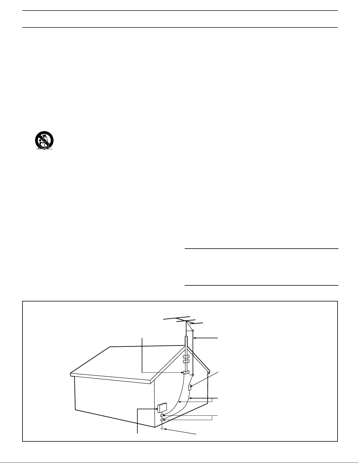
14. Outdoor Antenna Grounding - If an outside antenna is connected to
the receiver, be sure the antenna system is grounded so as to
provide some protection against voltage surges and built up static
charges.
Section 810 of the National Electric Code, ANSI/NFPA No. 70-1984,
provides information with respect to proper grounding of the mats
and supporting structure grounding of the lead-in wire to an
antenna discharge unit, size of grounding connectors, location of
antenna-discharge unit, connection to grounding electrodes and
requirements for the grounding electrode. See Fig. below.
15. Non-use Periods - The power cord of the appliance should be
unplugged from the outlet when left unused for a long period of
time.
16. Object and Liquid Entry - Care should be taken so that objects do
not fall and liquids are not spilled into the enclosure through
openings.
17. Damage Requiring Service - The appliance should be serviced by
qualified service personnel when:
A. The power supply cord or the plug has been damaged; or
B. Objects have fallen, or liquid has been spilled into the
appliance; or
C. The appliance has been exposed to rain; or
D. The appliance does not appear to operate normally or exhibits
a marked change in performance; or
E. The appliance has been dropped, or the enclosure damaged.
18. Servicing - The user should not attempt to service the appliance
beyond that described in the operating instructions. All other
servicing should be referred to qualified service personnel.
Note to the CATV system installer: This reminder is provided to call the
CATV system installer's attention to Article 820-40 of the NEC that
provides guidelines for proper grounding and, in particular, specifies that
the cable ground shall be connected to the grounding system of the
building, as close to the point of cable entry as practical.
Example of Antenna Grounding
as per NEC - National Electric Code
EXAMPLE OF ANTENNA GROUNDING AS PER NATIONAL ELECTRICAL CODE (NEC)
GROUND CLAMP
ELECTRIC SERVICE EQUIPMENT
ANTENNA LEAD IN WIRE
ANTENNA DISCHARGE UNIT
GROUNDING CONDUCTORS (NEC SECTION 810-21)
GROUND CLAMPS
POWER SERVICE GROUNDING ELECTRODE SYSTEM (NEC ART 250, PART H)
(NEC SECTION 810-20)
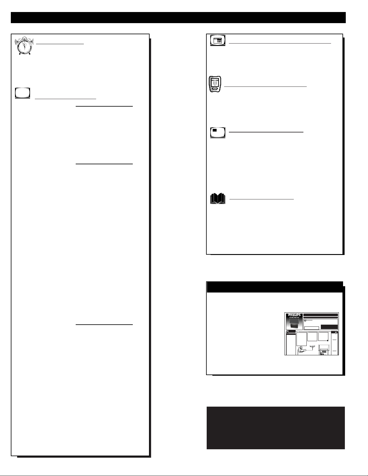
TABLE OF CONTENTS
Getting Started
Welcome/Product Registration...................2
Safety/Precautions .....................................................3
Table of Contents.......................................................4
Features, Model and Cabinet Information.................5
On-Screen Features
PICTURE MENU
✧Adjusting Color, Brightness, Sharpness,
Tint, Picture, and Color Temperature Controls ..6
✧Using Clearview and Video Enhance Controls...7
✧Adjusting the TV's Convergence Control...........8
✧Using the Flesh Correction Control ....................9
FEATURES MENU
✧Using the Analog Format Screen Control.........10
✧Setting the TV for Closed Captioning...............11
✧Setting the TV for Cable or Antenna Signals....12
✧Adding Channels in Memory (Automatically) .13
✧Adding Channels in Memory (Manually).........14
✧Setting the TV Clock.........................................15
✧Using the Sleep Timer Control .........................16
✧Adjusting the Channel Display Control............17
✧Using the Time/Channel Reminder Control......18
✧Using Parental Control/Content Advisory:
• Code Setup/Blocking Channels...............19-20
• Content Advisory - Movie Ratings .........21-22
• Parental Guidelines.......................................23
• Blocking Options/Review Settings...............24
✧Using the Channel Label Control......................25
✧Using the Language Selection Control..............26
SOUND MENU
✧Adjusting Bass, Treble, and Balance Sound
Controls.............................................................27
✧Setting the Bass Boost Control ........................27
✧Setting the TV for Stereo and SAP Programs ..28
✧Using the Incredible Surround Control.............29
✧Using the Volume Display Control...................29
✧Using the TV Speaker On/Off Control with
the Audio Output jacks .....................................30
✧Surround Sound Speaker Connections and
Variable Audio Output Control ........................31
✧Optional Surround Sound Connections ............32
✧Using the TV's Audio/Video Input and
Output Jacks ...............................................33-37
Monitor (HD) Control Operation
Connection of VGA and High Definition (HD)
Component Video Equipment .................................38
Adjusting of Monitor Display Controls...................39
Remote Control Operation
Setting the Auto Picture Control..............40-41
Using the Auto Sound Control.................................42
Using the Auto Surf Control....................................43
Picture-In-Picture (PIP)
How to Use PIP (Connections).............44-45
How to Use PIP with the TV Remote......................46
Selecting the Picture Source for PIP........................47
Adjusting PIP Color, Tint, and Size ........................48
More PIP Connections (Cable Converter)...............49
General Information
Tips if Something Isn’t Working...............50
Glossary of TV Terms .............................................51
Index ........................................................................52
Warranty ..................................................................53
Use the simple Set-Up Guide (supplied with
your TV information packet) for details on:
• Antenna Hook-ups
• First Time Set-Up
(Automatic Settings)
• Basic TV and Remote
Control Operation
• On-Screen Menu Use
SET-UP AND QUICK USE GUIDE
g
2
BEGIN
1
OR
3
STOP
4
Copyright © 2000 Philips Consumer Electronics Company. All rights reserved.
NOTE: This owner's manual is used with several
different television models. Not all features (and
drawings) discussed in this manual will necessarily
match those found with your television set. This is
normal and does not require you contacting your dealer
or requesting service.
12
1
11
2
10
3
9
4
8
5
7
6
BRIGHTNESS
PICTURE
SHARPNESS
SVM OFF
COLOR
TINT
VOLUME BAR ON
SET-U
Atypical ANT(enna)
Aand B connection (using a
common signal source and an
optional Signal Splitter):
If yourAntenna orCable TV
signal has a round cableconnector(75 ohm) on the end,
then you're ready to connect it
to the 75ohm Signal Splitter.
If yourantenna has flat twinlead wire (300 ohm), you first
need to attach the antenna wires
to the screws on a 300 to 75
ohm adapter before connecting
to the 75ohm Signal Splitter.
Round Cable
75ΩOhm
Getting Started
12
1
11
2
10
3
9
8
4
Warning/Precautions..................................1
5
7
6
Hooking Up Your TV................................1
How to Use the First Time Set-Up Control ..............2
Basic TVand Remote Control Operation.................3
How to Use the On-Screen Menu Controls...............4
WARNING: TO PREVENTFIRE OR SHOCK
HAZARD DO NOTEXPOSE THIS UNITTO
RAIN OR EXCESSIVE MOISTURE.
Connect yourAntenna or
Cable TVsignal to the single
75 ohm input plug on the twoway Signal Splitter (optional).
Then connect two lengths of RF
Coaxial Cable to the two Output
plugs on the two-way Signal
Splitter (F-type connector on
both ends).
Combination VHF/UHFAntenna
300 to 75ΩAdapter
(483521827003)
Twin Lead
Wire
- Outdoor or Indoor Antenna -
receives normal broadcast channels
2-13 (VHF) and 14-69 (UHF).
P ANDQUICKUSEGUIDE
TABLEOF CONTENTS
• For details on product registration, warranty,
and service refer to the other literature included
with your TVinformation packet.
Please retain all these materials and keep them
handy for future reference.
NOTE: This owner's manual is used with several different
television models. Not all features (and drawings) discussed in this manual will necessarily match those found
with yourtelevision set. This is normal and does not
require you contacting yourdealeror requesting service.
Connect the twin Output
plugs on the Signal Splitter to
the ANTAand ANT B inputs
on the rear of the TV. Push the
round connector end of the RF
Coaxial Cable onto the
ANT(enna) plug and screw it
down tight (if using threaded
cables).
Back of TV
SMART
HELP
Remember,
be sure to set the
TVfor the type signal you've connected (see "SETUP"
on page 2 of this
Guide.)
Your TVcan set
itself to select only
the channel numbers
on your Cable system (see “Setup"
page 2). If you use a
Cable Converter box,
set the TVto the
same channel as the
converter's CH 3/4
switch (on the rear of
the converter.)
To order any
optional accessory
contact your dealer
or call the toll-free
accessory orderin
HD Widescreen Television
ANTENNAOR
CABLETV
ANT(ENNA) A& B INPUTS
our TVhas two sepa-
Y
rate ANT(enna)/Cable
inputs on the rear of the
set. These two signal
inputs offer convenient
hook-up options for both
normal TVprogram viewing and Picture-In-Picture
(PIP) features.
The ANT(enna) Ainput is
intendedfor use and view-
ing on the TV’s main
screen. Your home’s primary Antenna, or Cable
TVsignal, should be connected to this input for
normal TVsetup, use and
feature operation.
The ANT(enna) B input is
a second, or auxiliary sig-
nal source, designed to
First Time Set Up - automatically sets the TV for
local channels, the correct picture signal (antenna or
cable), and assists in the setting of TV’s Guide Plus+
feature.
Pronto Remote Control - universal, learn remote
which controls virtually all IR devices, learns new
commands, and can be customized for personal
preferences. Features a large LCD backlit touchscreen.
Standard TV broadcast (VHF/UHF) or Cable TV
(CATV) channel capability as well as advanced
connectivity for high definition video and VGA.
Closed Captioning - allows the viewer to read TV
program dialogue or voice conversations as on-screen
text.
Automatic Programming of channels - for quick and
easy selection of favorite stations available in your
area.
Picture-In-Picture (PIP) - can show a TV program
and the direct video output from an accessory (VCR,
etc.) onto the TV screen at the same time.
Parental Control for “Censoring” - this feature can
block out channels to keep children from watching
undesirable programming. Parental Guideline and
Movie Rating settings can also be used as part of the
new Content Advisory Data system available with TV
programming.
Stereo TV - with a built-in audio amplifier and a twin
speaker system, reception of TV programs in both
broadcast stereo sound or (SAP) bilingual broadcast
are available.
Twin Antenna (A/B) Inputs - for easy displaying of
two separate signal sources on the TV. An A/B button
on the remote control switches the TV’s Main screen
between the two Antenna (A & B) Input options.
Audio/Video Jacks - for direct connections with
VCRs (and other accessories) for quality TV picture
and sound playback.Component Video Input
connectors are also available for high fidelity color
and picture resolution when using digital video source
material, such as DVD.
Surround Sound - this TV set contains external;
audio speaker connections for a more dynamic sound
effect capable within the today’s Home Cinema
environment.
Sleep-Timer - automatically turns the TV OFF at
preset time intervals.
Auto Button - for the control of TV Sound and
Picture levels. Use the Auto Button on the remote to
quickly select various audio modes matched to
specific types of TV programming; to select video
level adjustments for a variety of program sources;
and to make quick one button channel selection of up
to 10 of your favorite channels.
FEATURES
As you unpack your TV please note that the
following items have been included with your set:
• Owner's Manual
- Safety Tip Information
- Factory Service Center Locations
• Warranty Registration Card
• Remote Control Transmitter
• Batteries for Remote Control Use
Refer to the back of this manual for instructions
on the cleaning and care of the TV.
5
End-of-Life disposal
Your new projection television and its packaging
contain materials that can be recycled and reused.
Specialized companies can recycle your product
to increase the amount of reusable materials and
minimize the amounts which need to be properly
disposed.
Your product also uses batteries which should not
be thrown away when depleted, but should be
handed in and disposed of as small chemical
waste.
Please find out about the local regulations on how
to dispose of your old television, batteries, and
packaging materials whenever you replace
existing equipment.
High Definition Digital - Projection Television
capable of 1920 x 1080i interlaced imaging for
superior resolution and performance. Line doubling
circuitry and video processing technology able to
output progressive scan material with clean, stable
widescreen images. PixelMax optimum triple lens
system matched to first surface mirror and fine
pitched lenticular screen methods which amounts to
an incredible 1,620,000 pixels of display capability.
High Definition Component and RGB Inputs are
available as well for Y, Pb, Pr; horizontal/vertical
sync, and RGB/VGA monitor input operation modes.
Automatic Phosphor Aging Compensation (APAC)
- Automatic incremental shifting of TV screen
elements to prevent any onscreen image outline
retention or “screen burn” problems.
GUIDE Plus+®- Electronic TV Program guide which
provides for daily television channel listings,
descriptions of program content, sorting of shows by
subject themes, and a variety of other VCR
programming options. (See your separate GUIDE
Plus+
®
Owner’s Manual for further details.)
Because of continuous product improvements, the
information mentioned in the documents
accompanying your product are subject to change
without notice.
12
1
11
2
10
3
9
4
8
5
7
6
PICTURE MENU CONTROL ADJUSTMENTS
COLOR, BRIGHTNESS,
SHARPNESS, TINT, PICTURE
T
o adjust your TV color and
picture controls, select a TV
channel and follow the steps shown
below:
Select BRIGHTNESS,
PICTURE, COLOR, TINT, or
SHARPNESS picture control.
With the PICTURE MENU (1 of
3) onscreen, move the RED
highlight with the MENU
buttons. Then press the MENU (or
ok) button to select the feature.
Press the § or © arrow buttons
to adjust the selected control.
Press the Exit button to clear the
screen.
1
2
3
SMART HELP
Remember. When the
bar scale is centered, control
settings are at normal mid-range
levels.
BRIGHTNESS Press (-) or (+) until
dark parts of the picture show good
detail.
PICTURE Press (-) or (+) until
whitest parts of the picture are as
bright as you prefer.
COLOR Press (-) or (+) to add or
eliminate color.
TINT Press (-) or (+) to obtain
natural skin tones. (Also see Flesh
Correction on page 9 for more
information).
SHARPNESS Press (-) or (+) to
improve detail in the picture.
Select and then press MENU
(or ok) button to view
additional controls grouped
under same feature heading.
For Example: Tint,
Brightness, Picture, etc.
6
Note: A Color
Temperature control is
also available to set the
level or degree of color
intensity (especially on
white picture screen
elements). For example,
use the Color
Temperature (Picture Menu 3 of 3)
for the following settings:
COOL – makes whites, bluish
NORMAL – keeps whites, white.
WARM – makes whites, reddish.
PICTURE MENU
EXIT
3 OF 3
COLOR TEMPERATURE
MORE...
EXIT
NORMAL
WARM
COOL
COLOR TEMPERATURE
1
3
MAIN MENU
PICTURE
FEATURES
1ST TIME SETUP
Menu
ok
Exit
INFO
HDR PTV
Source
A/CH3/5
SOUND
EXIT
1
mute
channel
++
volume
++
PICTURE MENU
COLOR TINT
BRIGHT
SHARP
EXIT
COLOR
MIN
2
EXIT
PICTURE
CLEARVIEW
MORE...
1 OF 3
MAX
NEXT...
PICTURE MENU CONTROLS (CONTINUED)
C
learview is a sharpness feature
which smoothes out
background snow (or picture noise)
without losing picture image detail
or crispness.
Select CLEARVIEW control.
With the PICTURE MENU (1 of 3)
onscreen, move the RED highlight
with the MENU buttons. Then
press the MENU (or ok) button to
select the feature.
Press the MENU ▲▼ buttons to
move the RED highlight. Press the
center MENU button to select (
U)
the ENHANCED mode.
Press the Exit button to clear the
screen.
CLEARVIEW
1
2
3
7
Note: An additional
Picture Menu
“VIDEO
ENHANCEMENT”
control (similar in
function and use as
the Sharpness control)
is also available to
further improve picture intensity and
detail, particularly for the playback of
DVD player source material.
Selection and adjustment of the
Video Enhancement control (Picture
Menu 2 of 3) is the same as with other Color and Picture Menu
control options.
PICTURE MENU
FLESH CORRECTION
EXIT
2 OF 3
MORE...
CONVERGENCE
VIDEO ENHANCEMENT
EXIT
MIN
MAX
VIDEO ENHANCEMENT
1
3
MAIN MENU
PICTURE
FEATURES
1ST TIME SETUP
DN
Menu
ok
Exit
INFO
HDR PTV
Source
A/CH3/5
SOUND
EXIT
1
mute
channel
++
volume
++
PICTURE MENU
COLOR TINT
BRIGHT
SHARP
EXIT
CLEARVIEW
NORMAL
ENHANCED
2
EXIT
PICTURE
CLEARVIEW
MORE...
1 OF 3
NEXT...
PICTURE MENU CONTROLS (CONTINUED)
RED/BLUE CONVERGENCE
C
onvergence is the correct
lining up of the red and blue
light paths on the TV screen.
NOTE: If no color fringing (see
Smart Help) shows, then no
Convergence adjustments are
necessary for your TV.
Select CONVERGENCE
control.
With the PICTURE MENU (2 of
3) on screen, move the RED
highlight with the MENU
buttons. Then press the MENU (or
ok) button to select the feature.
If there is RED or BLUE color
fringing (see note below) on your
PTV, press the MENU ▲▼
buttons to move the highlight.
Press the MENU (or ok) button to
select the Align Red or Align Blue
Convergence control.
Press the MENU buttons
to move the red or blue cross
directly over the white cross on the
TV screen.
The red or blue cross is properly
adjusted when it is completely
merged with the white cross. (No
color appears around the edge of
the white cross).
Press the Exit button to clear
the screen when convergence
adjustments are complete.
1
2
3
SMART HELP
Remember. Convergence
has been set at the factory for
best viewing, but if one or more of
the (red or blue) colors appear
around the edges of objects (color
fringing) follow the steps given in
this section.
4
8
NOTE: Adjustments for
“Multi-Point” on-screen color
fringing can also be made as
part of the TV’s Convergence
control system. Follow the TV’s
on-screen menu directions to
select individual screen areas that can
be readjusted and set for varying
red/blue color fringing conditions.
These multi-point settings can then be
“Saved” to memory for the specific areas of the TV
screen (or Factory Settings for convergence can be
recalled and put back into place for use).
CONVERGENCE MULTI POINT
CONVERGE RED POINTS
CONVERGE BLUE POINTS
RESTORE FACTORY SETTINGS
SAVE ADJUSTMENTS
BACK
CONVERGE RED POINTS
USE TO ADJUST
DIGIT 2, 4, 6, 8 TO MOVE CURSOR
PRESS MENU TO RETURN
PRESS MENU NOW TO CONTINUE
MULTI-POINT
CONVERGENCE
MAIN MENU
PICTURE
FEATURES
1ST TIME SETUP
SOUND
EXIT
PICTURE MENU
COLOR TINT
BRIGHT
SHARP
PICTURE
CLEARVIEW
EXIT
PICTURE MENU
1
DN
Menu
Exit
INFO
HDR PTV
Source
ok
A/CH3/5
mute
channel
++
volume
++
CONVERGENCE
FLESH CORRECTION
VIDEO ENHANCEMENT
EXIT
MORE...
1 OF 3
MORE...
2 OF 3
1
4
2
3
CONVERGENCE MENU
ALIGN RED
ALIGN BLUE
CONVERGE MULTI POINT
BACK
PRESS TO ALIGN RED
PRESS MENU TO RETURN
U
se the Flesh Correction
control to keep skin tone hues
(or facial tint) from varying from
TV channel to TV channel.
Select FLESH
CORRECTION control.
With the PICTURE MENU (2 of
3) on screen, move the RED
highlight with the MENU
buttons. Then press the MENU (or
ok) button to select the feature.
Press the MENU ▲▼ buttons
to move the RED highlight. Press
the MENU (or ok) button to turn
(
U) the FLESH CORRECTION
control ON.
Press the Exit button to clear
the screen.
FLESH CORRECTION
1
2
3
PICTURE MENU CONTROLS (CONTINUED)
9
1
3
MAIN MENU
PICTURE
FEATURES
1ST TIME SETUP
DN
Menu
Exit
INFO
HDR PTV
ok
Source
A/CH3/5
SOUND
EXIT
1
mute
channel
++
volume
++
PICTURE MENU
COLOR TINT
BRIGHT
SHARP
EXIT
PICTURE MENU
CONVERGENCE
FLESH CORRECTION
VIDEO ENHANCEMENT
EXIT
PICTURE
CLEARVIEW
MORE...
1 OF 3
MORE...
2 OF 3
2
FLESH CORRECTION
ON
OFF
EXIT
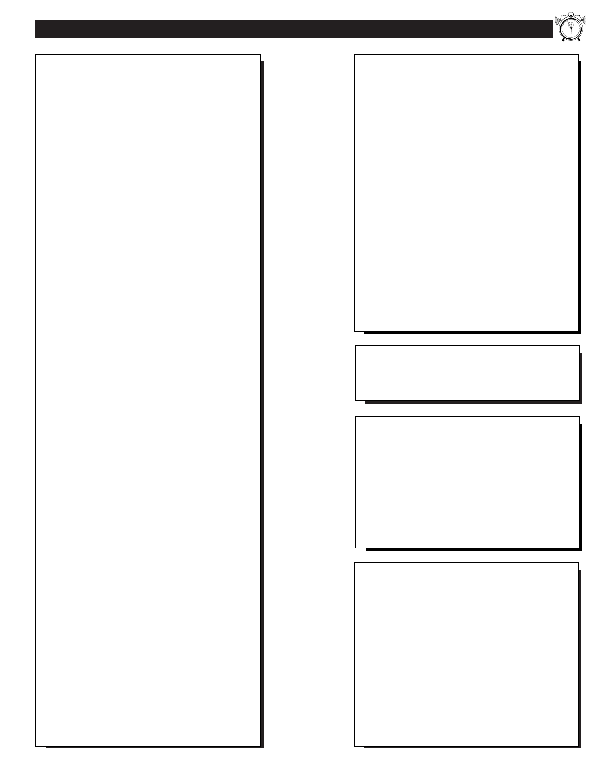
FEATURE MENU CONTROL ADJUSTMENTS
ANALOG FORMAT
Y
our TV is able to deliver
lifelike, widescreen picture (or
“home cinema” experience) that is
promised with High Definition TV
viewing. The Analog Format
control can be used to expand
conventional 4:3 aspect ratio
(width-to-height) broadcasts in
order to fit your TV’s widescreen
format; or to reset the screen to
best match the current
programming.
Select ANALOG FORMAT
control.
With the FEATURES MENU (1 of
5) on screen, move the RED
highlight with the MENU
buttons. Then press the MENU (or
ok) button to select the feature.
Press the MENU ▲▼ buttons
to move the RED highlight. Press
the MENU (or ok) button to select
(U) the desired screen aspect ratio
or screen display control.
Press the Exit button to clear
the screen.
1
2
3
10
SMART HELP
Note: In the past the
relationship between a TV
screen’s width to height, or aspect
ratio, has historically been 33%
wider than the picture screen
height (or a 4:3 aspect ratio). The
widescreen format of your TV
screen is nearly 80% greater than
its measure height (which
accounts for a 16:9 aspect ratio).
The reason for the 16:9 aspect
ratio screen is that it allows for the
dramatic and lifelike viewing of
original version movies and
cinemas (similar to the type found
in your local theaters). And the
16:9 aspect ratio widescreen is
also a good visual match for how
our eyes work in a horizontally
oriented field of view and action
plane.
Panoramic - Conventional
picture is expanded to fill the
full 16:9 aspect ratio screen
area. Most of the non-linear
picture expansion is performed
toward the outer edges so that
correct proportions are
retained in the center of the
screen.
4:3 (Standard) Conventional TV picture
format shows on the screen.
Black bar areas show on the
side margins of the screen.
16:9 (Expand) - Full
widescreen mode with linear
expansion to view HD
program broadcasts. Used for
material originally produced in
16:9 format.
Theater 1/2 - Expanded zoom
modes with picture images
increased in magnification.
Designed for use with
“letterbox” or cropped movie
images such as found with
Cinemascope or Cinerama
type program material.
Note: With the Theater modes
there can be some loss of
information at the edges as the
picture expands to fill the
screen.
Note: The Analog Format
button on the Pronto Remote
(touchscreen 1 of 5) can also
be used to quickly select the
various aspect ratio screen
control settings for PTV
viewing.
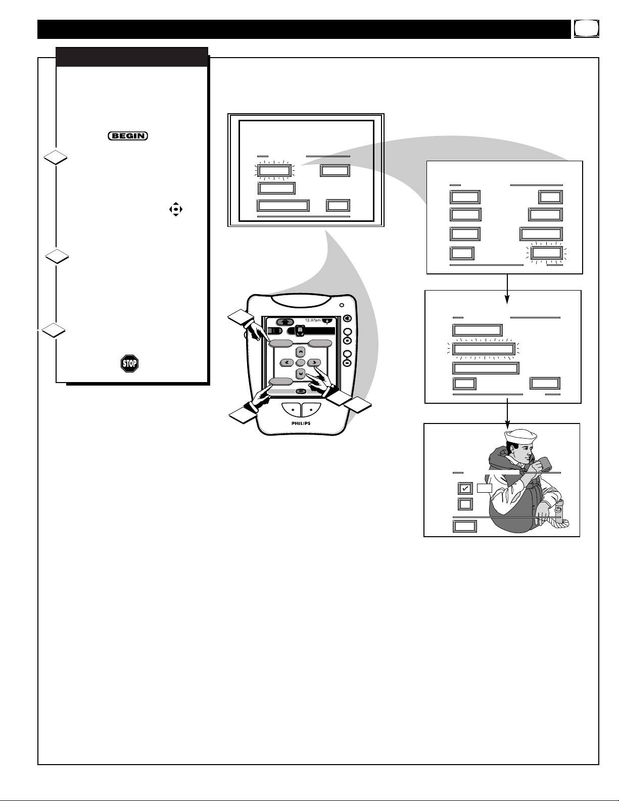
Building Trade News
Building Trade News
Building Trade News
Building Trade News
PANORAMIC
4 X 3
16 X 9
THEATER 1/2
MAIN MENU
PICTURE
FEATURES
1ST TIME SETUP
SOUND
EXIT
FEATURE MENU
ANALOG
FORMAT
CABLE
TUNING
DN
1
Menu
Exit
INFO
3
Auto
Analog Format
INFO
ok
Power
Sleep
HDR PTV
Source
A/CH3/5
HDR PTV
Status
A/CH1/5
channel
volume
CLOSED
CAPTIONS
EXIT
mute
channel
++
volume
++
1
2
mute
++
++
ANALOG FORMAT
PANORAMIC
4 X 3
16 X 9
THEATER 1
THEATER 2
EXIT
CHANNEL
MEMORY
MORE...
1 OF 5
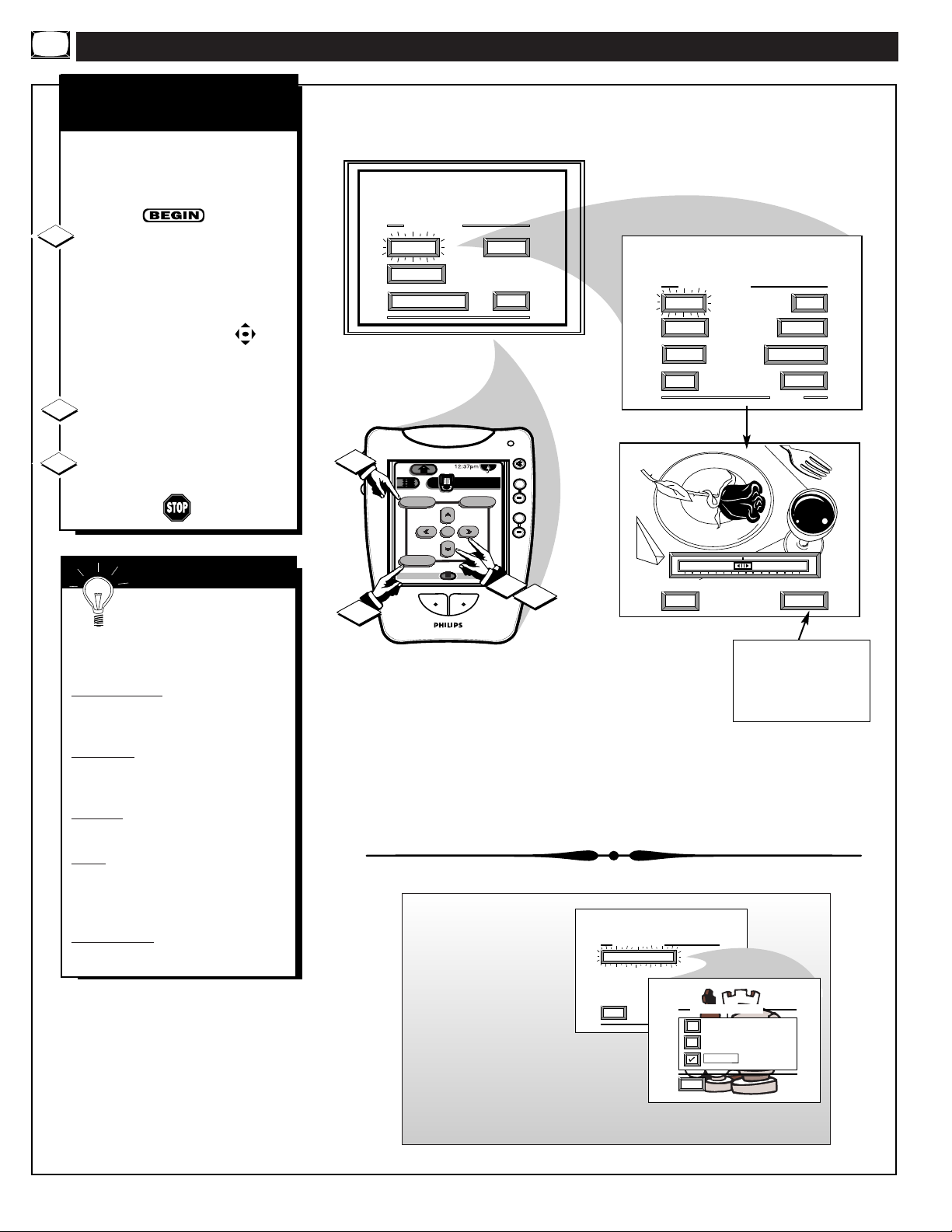
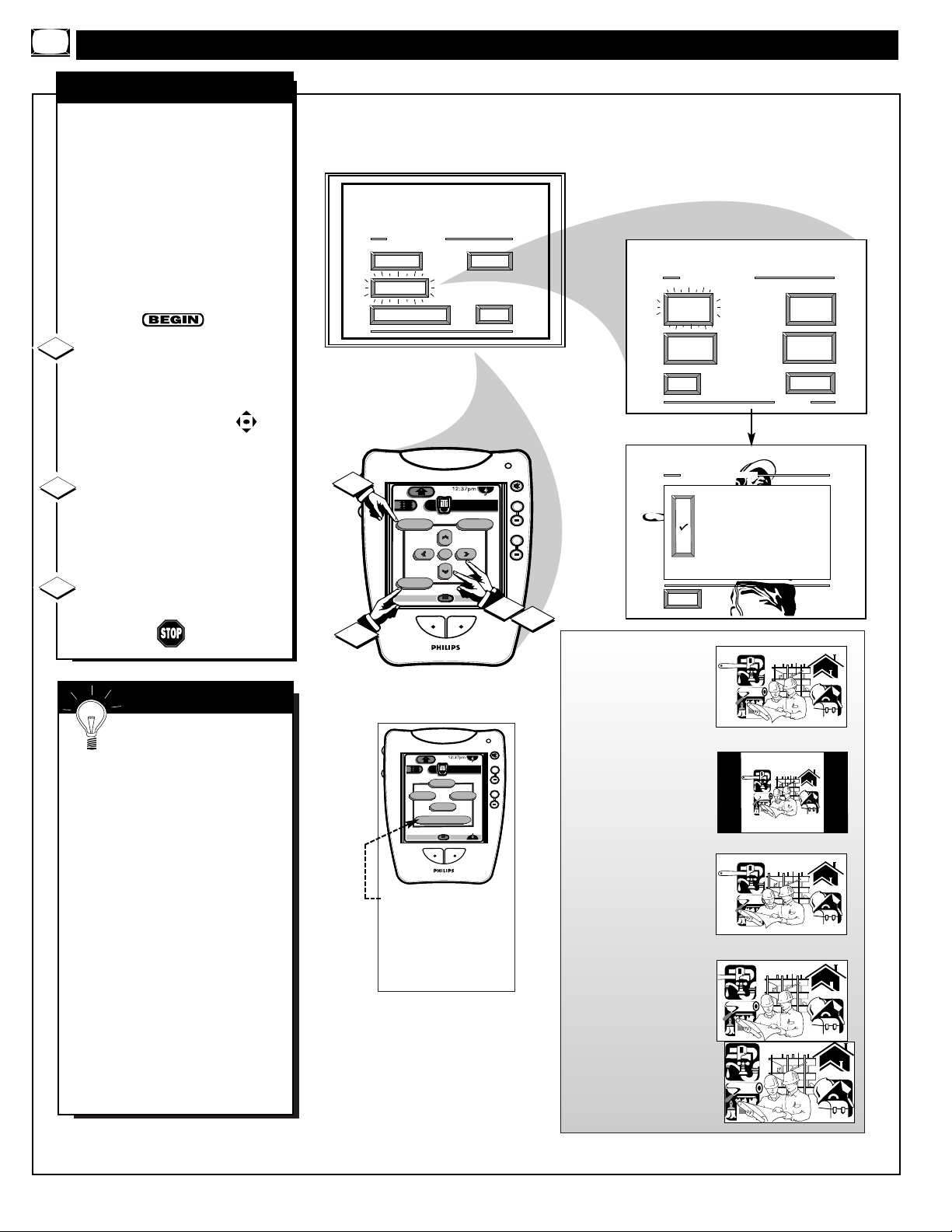
C
losed Captioning (CC) allows
you to read the voice content of
television programs on the TV
screen. Designed to help the hearing
impaired this feature uses on-screen
"text boxes" to show dialogue and
conversations while the TV program
is in progress.
Select CLOSED
CAPTIONING control.
With the FEATURES MENU (1 of
5) on screen, move the RED
highlight with the MENU
buttons. Then press the MENU (or
ok) button to select the feature.
Press the MENU ▲▼ buttons to
move the RED highlight. Press the
MENU (or ok) button to select (U)
the desired Closed Caption mode For Example: "ALWAYS ON" and
"CAPTION 1".
CAPTION 1, 2, 3, 4:
dialogue (and descriptions)
for the action on the captioned
TV program shows on-screen.
(See Important Note on this
page.)
TEXT 1, 2, 3, 4:
often used for channel guide,
schedules, or bulletin board
information for CC programs.
After making your Caption mode
selection, press the Exit button to
clear the TV screen. The selected
Closed Caption mode will be active.
To cancel, set the Closed Captioned
feature to OFF when finished.
1
2
FEATURE MENU CONTROLS (CONTINUED)
NOTE: Not all TV programs and product commercials are made for broadcast
with Closed Caption (CC) information included. Neither are all Closed Caption
modes (CAPTION 1-4; or TEXT 1-4) necessarily being used by a broadcast station
during the transmission of a closed caption program. Usually "CAPTION 1" is the
most used mode to view captioned material. Refer to your area's TV program
listings for the stations and times of Closed Caption shows.
3
CAPTION 1 mode
Example Screen Display
FULL SCREEN TEXT
will block TV screen from viewing
Closed Caption information will usually appear
in black and white (although some broadcasters
or networks may occasionally use color to
highlight or draw attention to certain areas.)
CLOSED CAPTION
NOTE: The ON DURING
MUTE ONLY control can be
used to set the TV to turn the
Closed Caption mode "ON"
whenever the MUTE button
on the remote is pressed.
SMART HELP
Remember. Broadcast
stations will often use
spelling abbreviations, symbols,
dropouts and other grammatical
shortcuts in order to keep pace
with the on-screen action. These
type factors vary upon the source
of the captioned text material and
do not indicate a need for service
on the part of the TV.
11
FEATURE MENU
ANALOG
FORMAT
CLOSED
CAPTIONS
EXIT
CLOSED CAPTION
ALWAYS ON
ALWAYS OFF
ON DURING MUTE ONLY
CAPTION 1
CAPTION 2
CAPTION 3
CAPTION 4
EXIT
CABLE
TUNING
CHANNEL
MEMORY
MORE...
1 OF 5
TEXT 1
TEXT 2
TEXT 3
TEXT 4
1
MAIN MENU
PICTURE
FEATURES
1ST TIME SETUP
DN
Menu
Exit
INFO
HDR PTV
ok
SOUND
EXIT
mute
channel
++
Source
A/CH3/5
volume
++
1
2
3
JOHN: Why did they move the
meeting up to this week?
MARSHA: I don't know, but they
are pushing to close the deal.
CLOSE CAPTION PROGRAMS ON WXYZ
ALL ITEMS ARE EASTERN STANDARD TIME (EST)
CHECK LOCAL LISTINGS
FOR TIMES IN YOUR AREA
6:00 TOP OF THE MORNING
10:00 THE BEST LITTLE CALL-IN SHOW EVER
12:00 NOONDAY NEWS
1:30 AS YOUR LIFE TURNS MY WORLD AROUND
6:00 WORLD NEWS FOR TODAY
9:00 PLAYHOUSE MOVIE OF THE WEEK
FEATURE MENU CONTROLS (CONTINUED)
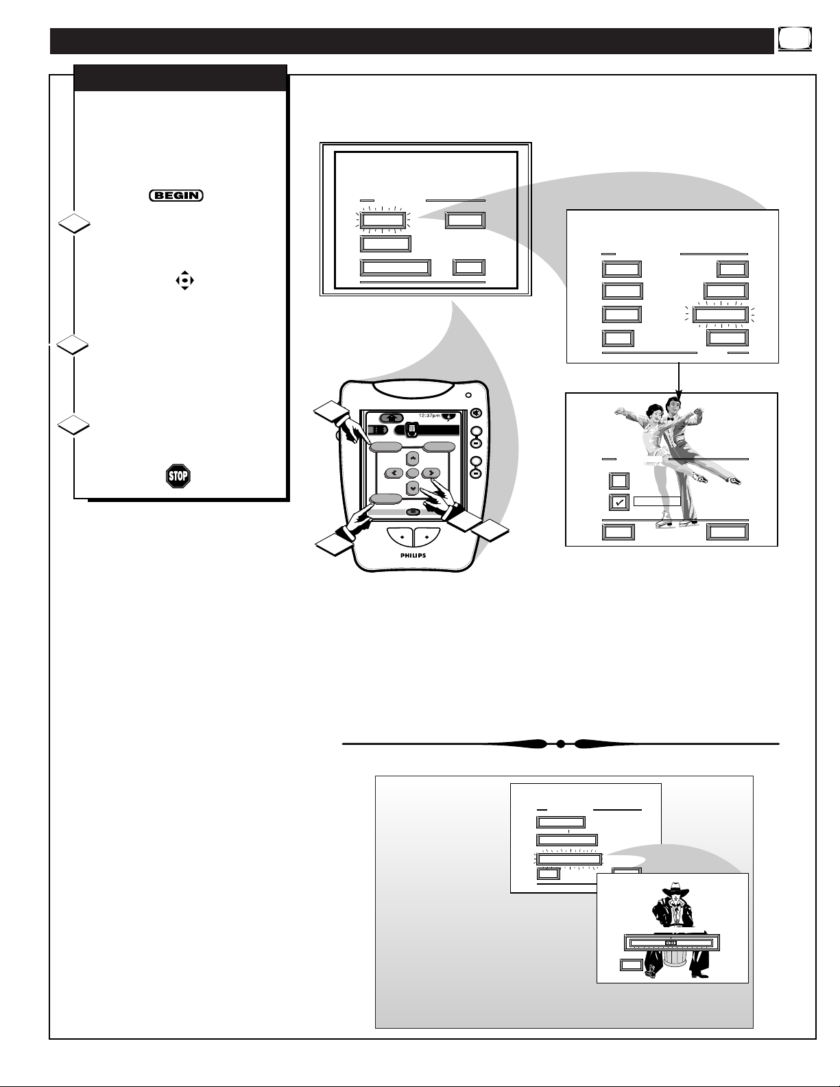
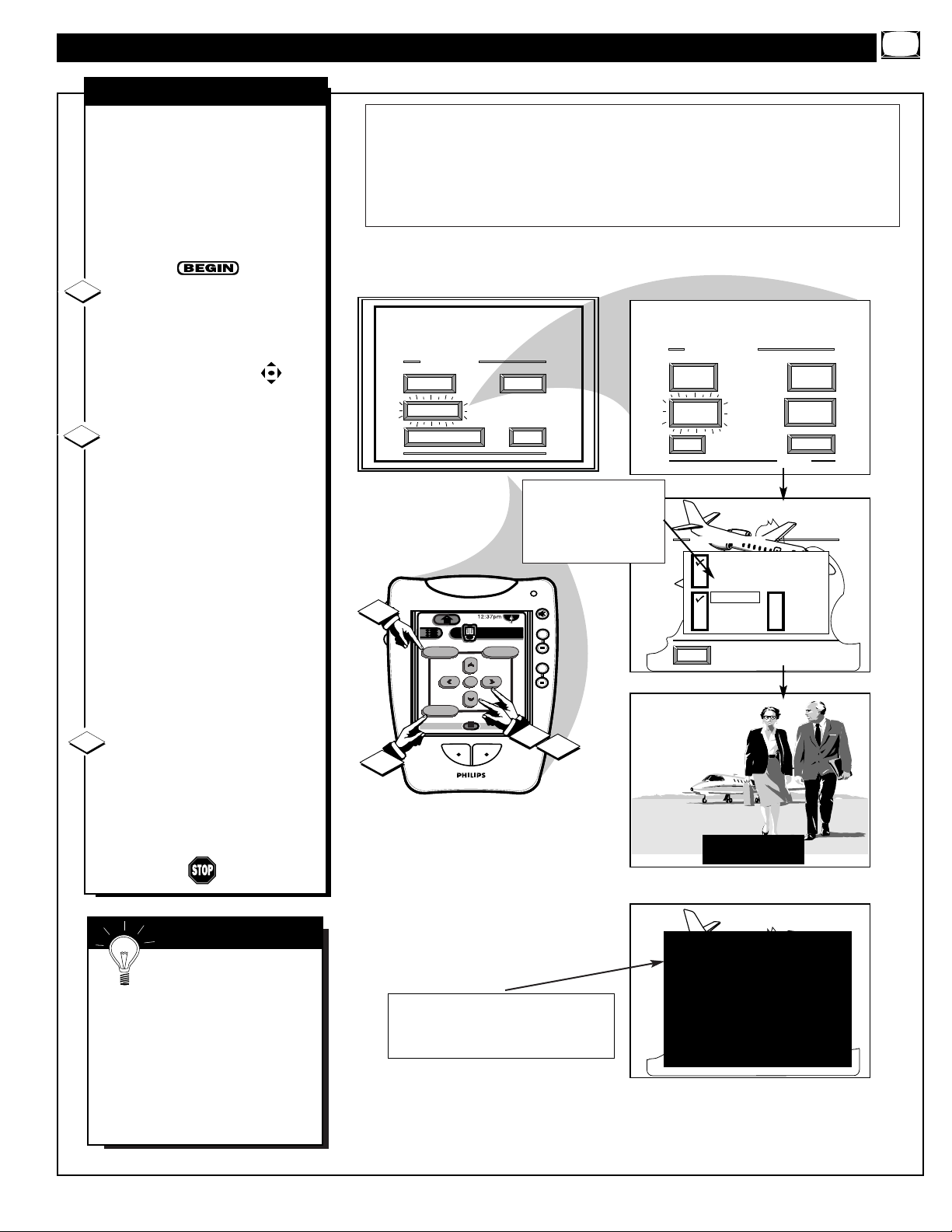
Y
ou need to make sure the TV is
set to pick up either Cable TV
or Antenna signals. In other words,
the TV needs to know if you
connected a Cable TV signal or a
normal antenna to its ANTENNA
plug.
NOTE: If you went through First
Time Setup (in your Quick Use
Guide), this task has already been
completed for you.
Select CABLE CHANNEL
TUNING control.
With the FEATURES MENU (1 of
5) on screen, move the RED
highlight with the MENU
buttons. Then press the MENU (or
ok) button to select the feature.
Press the MENU ▲▼ buttons
to move the RED highlight. Press
the center MENU button to select
(
U) the desired mode - For
Example: CABLE.
CABLE- If you DO have
Cable TV connected
to the TV. Channels
1-125 available.
NORMAL- If you have an
Antenna connected
to the TV. Channels
2-69 available.
Press the Exit button to clear
the screen.
CABLE TUNING
1
2
3
12
Note: Both ANT(enna) A and ANT B inputs
on the rear of the TV can be set for the correct
connected signal (either an Antenna or Cable
TV source).
1
3
MAIN MENU
PICTURE
FEATURES
1ST TIME SETUP
DN
Menu
ok
Exit
INFO
HDR PTV
Source
A/CH3/5
SOUND
EXIT
1
mute
channel
++
volume
++
FEATURE MENU
ANALOG
FORMAT
CLOSED
CAPTIONS
EXIT
CABLE TUNING
CABLE ANT A
NORMAL ANT A
CABLE ANT B
NORMAL ANT B
CABLE
TUNING
CHANNEL
MEMORY
MORE...
1 OF 5
2
EXIT
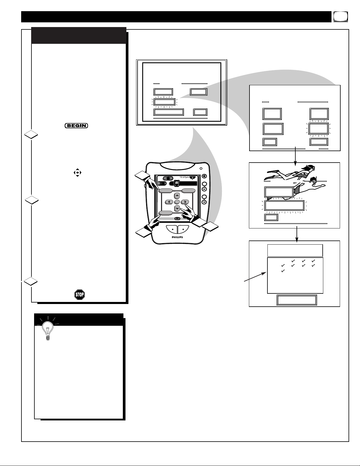
Y
our TV can automatically set itself
for local area (or Cable TV)
channels. This makes it easy for you
to select only the TV stations in your
area when the CHANNEL
▲▼
buttons are pressed.
NOTE: If you went through First
Time Setup (in your Quick Use
Guide), this task has already been
completed for you.
Select CHANNEL MEMORY
(START AUTO-PROGRAMMING)
control.
With the FEATURES MENU (1 of 5)
on screen, move the RED highlight
with the MENU buttons. Then
press the MENU (or ok) button to
select the feature.
Press the MENU ▲▼ buttons to
select AUTO-PROGRAMMING ON,
then press the Menu (or ok) button to
begin.
The TV shows which channel
numbers are "SAVED" (
U) as they
are added into memory.
"Auto-programming CHANNEL
MEMORY is finished" shows when
the TV is through adding channels.
Press the Exit button to clear the
screen.
CHANNEL MEMORY
AUTO-PROGRAMMING
1
2
3
FEATURE MENU CONTROLS (CONTINUED)
U Channel Numbers are
Saved in Memory
SMART HELP
Try it out. Press the
CHANNEL▲▼ buttons
and see which channels you can
select.
Remember, an Antenna or Cable
TV signal must first be connected
to your PTV so that channels can
be saved.
If you want to delete any
unwanted channels from the TV's
memory, see "ADD/DELETE
CHANNELS" on the next page.
13
MAIN MENU
PICTURE
FEATURES
1ST TIME SETUP
SOUND
EXIT
FEATURE MENU
ANALOG
FORMAT
CABLE
TUNING
CLOSED
CAPTIONS
EXIT
1
DN
Menu
Exit
INFO
HDR PTV
Source
ok
A/CH3/5
mute
channel
++
volume
++
1
2
CHANNEL MEMORY
ADD/DELETE
CHANNELS
START
AUTO-PROGRAMMING
EXIT
CHANNEL
MEMORY
MORE...
1 OF 5
3
AUTO-PROGRAMMING CHANNEL
MEMORY FOR ANT A
1 2 3 4
5 6 7 8
9 1O 11 12
13 14 15 16
17 18 19 20
21 22 23 24
Press "M" to
Stop Auto-Program
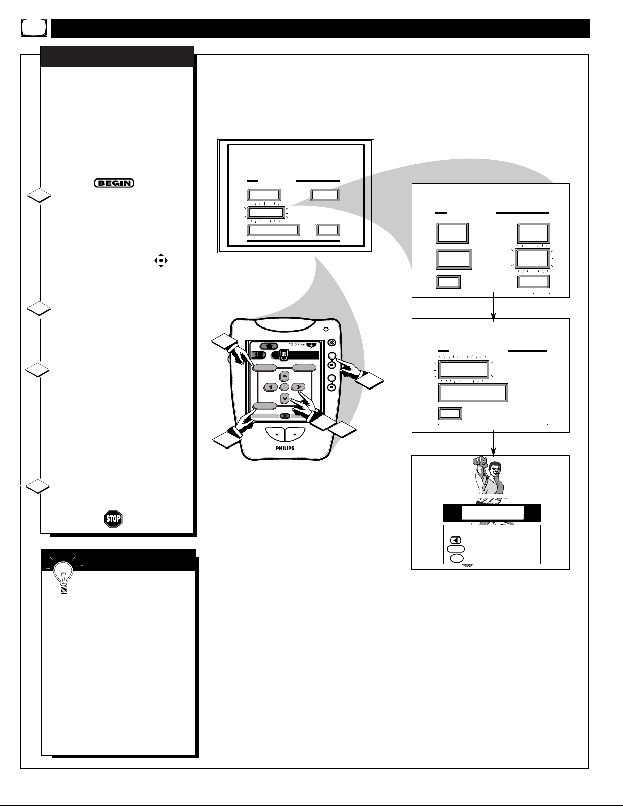
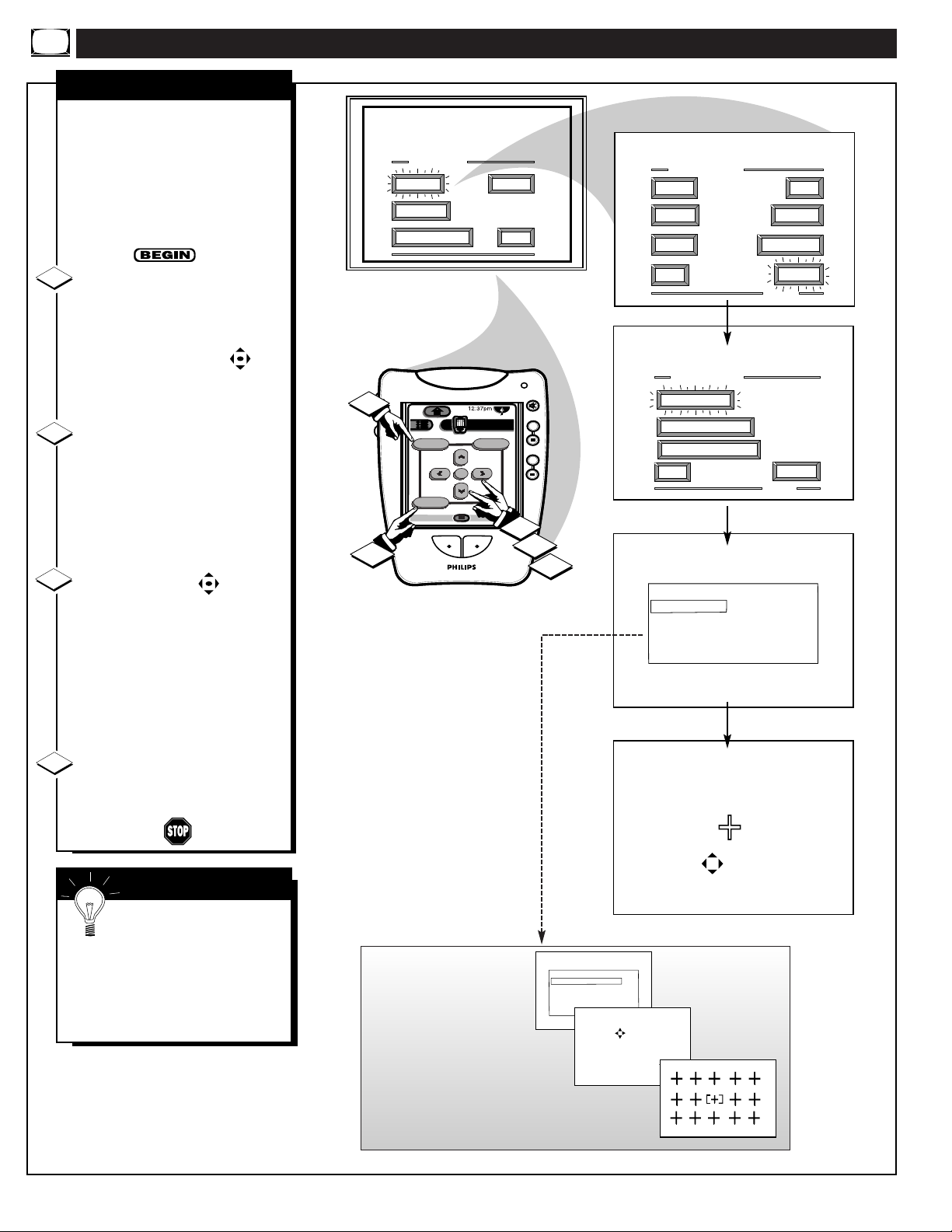
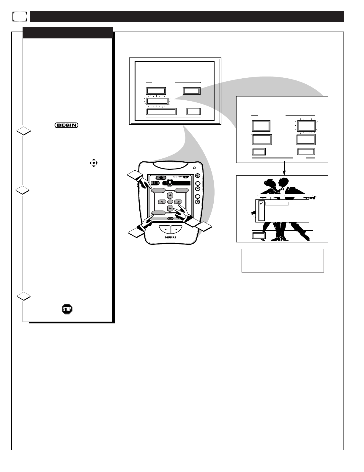
FEATURE MENU CONTROLS (CONTINUED)
A
uto-Programming (see
previous page) adds all the
channels it can find (on your
Antenna or Cable TV system) into
the TV's memory. Add/Delete
Channels makes it easy for you to
add other channels, or drop
unwanted channels, from the list of
channels in the TV's memory.
Select CHANNEL MEMORY
(ADD/DELETE CHANNELS)
control.
With the FEATURES MENU (1
of 5) on screen, move the RED
highlight with the MENU
buttons. Then press the MENU (or
ok) button to select the feature.
Press the CHANNEL (+)/(-)
(or number buttons on the Pronto’s
touchscreen 2 of 5) to select the
channel you want to add or delete.
Press the MENU © button to
ADD the channel into the TV's
memory.
Press the MENU
§ button to
DELETE the channel from
memory.
Repeat steps 2 and 3 for each
channel you wish to add or delete.
Press the Exit button to clear the
screen when through.
ADD/DELETE CHANNELS
1
2
3
4
SMART HELP
Remember. A separate
ADD/DELETE CHANNEL
memory may also be created for
the ANT(enna) B Input on the rear
of the set (if an Antenna or Cable
TV signal has been connected).
Press the “SOURCE” button on
the remote, while in the
ADD/DELETE CHANNEL
mode, to switch between the ANT
A and ANT B channel memory
lists. Then follow steps 2 and 3 as
shown above to add or delete the
desired channels.
14
1
4
MAIN MENU
PICTURE
FEATURES
1ST TIME SETUP
DN
Menu
ok
Exit
INFO
HDR PTV
Source
A/CH3/5
SOUND
EXIT
channel
volume
1
FEATURE MENU
ANALOG
FORMAT
CLOSED
CAPTIONS
EXIT
mute
++
++
2
CHANNEL MEMORY
ADD/DELETE
CHANNELS
START
AUTO-PROGRAMMING
EXIT
CABLE
TUNING
CHANNEL
MEMORY
MORE...
1 OF 5
3
ADD/DELETE CHANNEL
Channel 19 Added
for ANT A
SELECT CHANNEL
to DELETE CHANNEL
SOURCE
for ANT B
when FINISHED
M
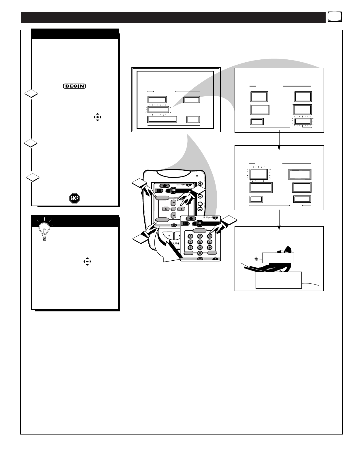
FEATURE MENU CONTROLS (CONTINUED)
SET CLOCK
Y
our TV comes with an on-
screen clock. During normal
operation the clock appears on the
screen with every channel change
(and when the STATUS button is
pressed).
Select SET CLOCK control.
With the FEATURES MENU (2 of
5) on screen, move the RED
highlight with the MENU
buttons. Then press the MENU (or
ok) button to select the feature.
Press the remote's number
buttons (on the Pronto’s
touchscreen 2 of 5) to set the time
clock.
Press the Exit button to set the
clock in operation and clear the
screen.
1
2
3
Remember, be sure to
press "0" first and then the
hour number for single digit
entries.
The remote's MENU buttons
can also be used to set the hours,
minutes and AM/PM portions of
the clock.
PTV Clock settings may be lost
when the TV is unplugged (or AC
power to the set is interrupted).
SMART HELP
15
1
3
MAIN MENU
PICTURE
FEATURES
1ST TIME SETUP
DN
Menu
Exit
INFO
HDR PTV
ok
Source
1
A/CH3/5
SOUND
+100
EXIT
INFO
mute
channel
++
1
volume
++
Status
HDR PTV
Surf
A/CH2/5
FEATURE MENU
ANALOG
FORMAT
CLOSED
CAPTIONS
EXIT
FEATURE MENU
SET
CLOCK
HALF HOUR
REMINDER
EXIT
CABLE
TUNING
CHANNEL
MEMORY
MORE...
1 OF 5
PARENTAL
CONTROL
CHANNEL
DISPLAY
MORE...
2 OF 5
2
SET CLOCK
9 : 19 AM
PLEASE ENTER THE
CURRENT HOUR
FEATURE MENU CONTROLS (CONTINUED)
H
ave you ever fallen asleep in
front of the TV only to have it
wake you up at two in the morning
with a test pattern screeching in
your ears? Well, your TV can save
you all that trouble by
automatically turning itself off.
Press the SLEEP button on the
Pronto remote control (touchscreen
1 of 5).
Press the Sleep button
repeatedly to pick the amount of
time (15 minutes to 2 hours ahead)
before the PTV will turn itself off.
Press the Status (or Exit) button
to clear the screen after you have
set the time for the TV to turn off.
1
2
3
Remember, to see how
many minutes are left before
the TV shuts itself off, reselect the
SLEEP TIMER control screen.
To stop a SLEEP TIMER setting,
reset the timer back to OFF.
(Turning the PTV off and on, or
pressing a button during the last
minute of a timer setting, will also
cancel a setting.)
A few seconds before the TV is to
shut off a message will come on the
screen telling you GOOD NIGHT.
SMART HELP
SLEEP TIMER
16
SET SLEEP TIMER
1 : 15
PRESS "SLEEP" TO CHANGE
DN
HDR PTV
Power
Auto
Analog Format
INFO
Status
Sleep
A/CH1/5
mute
channel
3
++
volume
++
1
2

FEATURE MENU CONTROLS (CONTINUED)
W
ith the Channel Display
control you can change the
size and location of the on screen
channel and clock information.
Select CHANNEL DISPLAY
control.
With the FEATURES MENU (2
of 5) on screen, move the RED
highlight with the MENU
buttons. Then press the MENU (or
ok) button to select the feature.
Press the MENU ▲▼ and
MENU (or ok)
buttons to
highlight and select (
U) the
LARGE or SMALL display
control.
Press the Exit button to clear
the screen.
CHANNEL DISPLAY
1
2
3
17
SMART HELP
Try it out. Press the
CHANNEL ▲▼ buttons
and you should see the Display
Size you selected.
Remember. The SMALL SIZE
display shows only the channel
number, not the time (or clock).
1
3
MAIN MENU
PICTURE
FEATURES
1ST TIME SETUP
DN
Menu
Exit
INFO
HDR PTV
ok
A/CH3/5
SOUND
Source
EXIT
FEATURE MENU
ANALOG
FORMAT
CLOSED
CAPTION
EXIT
FEATURE MENU
SET
mute
channel
++
volume
++
1
2
CLOCK
HALF HOUR
REMINDER
EXIT
CHANNEL DISPLAY
LARGE
SMALL - Channel/Label
CABLE
TUNING
CHANNEL
MEMORY
MORE...
1 OF 5
PARENTAL
CONTROL
CHANNEL
DISPLAY
MORE...
2 OF 5
EXIT

W
ith the Half Hour Reminder
control the TV automatically
shows you the current time and
channel every thirty minutes.
Select HALF HOUR
REMINDER control.
With the FEATURES MENU (2
of 5) on screen, move the RED
highlight with the MENU
buttons. Then press the MENU (or
ok) button to select the feature.
Press the MENU ▲▼ and
MENU (or ok)
buttons to
highlight and select (
U) the
EVERY HALF HOUR item.
Press the Exit button to clear
the screen.
HALF HOUR REMINDER
1
2
3
FEATURE MENU CONTROLS (CONTINUED)
18
SMART HELP
Remember. The Time
and Channel Reminders will
show on the hour and the halfhour for about five seconds.
1
3
MAIN MENU
PICTURE
FEATURES
1ST TIME SETUP
DN
Menu
ok
Exit
INFO
SOUND
HDR PTV
Source
A/CH3/5
EXIT
FEATURE MENU
ANALOG
FORMAT
CLOSED
CAPTIONS
EXIT
FEATURE MENU
SET
mute
channel
++
volume
++
1
2
CLOCK
HALF HOUR
REMINDER
EXIT
HALF HOUR REMINDER
OFF
EVERY HALF HOUR
CABLE
TUNING
CHANNEL
MEMORY
MORE...
1 OF 5
PARENTAL
CONTROL
CHANNEL
DISPLAY
MORE...
2 OF 5
EXIT

FEATURE MENU CONTROLS (CONTINUED)
P
arental Control allows parents
to block out, or "censor", any
channels they think children should
not watch. A channel placed under
Parental Control cannot be viewed
until a correct access code is used to
unlock the channel for viewing.
First let's set your Parental Code:
Select the PARENTAL
CONTROL.
With the FEATURES MENU (3 of
5) on screen, move the RED
highlight with the MENU
buttons. Then press the MENU (or
ok) button to select the feature.
"CHANNEL BLOCKING" and
"SETUP CODE" show on screen.
Press the MENU and MENU
(or ok) buttons to highlight and
select the SETUP CODE item.
Press 0, 7, 1, 1 on the remote
(touchscreen 2 of 5).
"XXXX" shows on the ACCESS
CODE SETUP screen as you press
the number buttons.
"INCORRECT ACCESS CODE TRY AGAIN" will also show on the
screen.
Press 0, 7, 1, 1 on the remote
again.
"Next Enter Your New Access
Code" shows on the screen.
Enter a new four digit number
code using the remote.
"Access Code Changed" shows on
the screen to let you know the new
code has been set.
Continue to the next page to find out how
to "BLOCK" channels from viewing.
1
2
3
4
5
SMART HELP
Parents - it isn't possible
to unlock or defeat your
Censor Code without changing to
a new code number. So if your
Code number changes, and you
didn't change it yourself, then you
will know that someone has
altered the code and the blanked
out channel has been viewed.
NOTE:Your TV left the factory with the Parental Code set to "0000". If you are using
your TV and the Parental Control for the first time, and don't want to SETUP a new
Access code number, you can use the "0000" number to block channels - see next page.
The "0711" Parental Code (shown on this page) is given as a default or way to reset the
Code when the current Access number is not known.
19
• Press MENU © to go on and start to
"block" channels.
• Press MENU § button (on to go to
"Content Advisory" (or TV and
Movie Ratings system of channel
blocking).
• Press the MENU (or ok) button to
return to the Parental Control Menu
screen.
• Press Exit to clear the screen.
PARENTAL CONTROL
SETUP CODE NUMBER
FEATURE MENU
2
1
MAIN MENU
PICTURE
FEATURES
1ST TIME SETUP
DN
Menu
Exit
INFO
HDR PTV
ok
Source
A/CH3/5
5
SOUND
+100
4
ANALOG
FORMAT
CLOSED
CAPTIONS
EXIT
mute
2
channel
++
1
volume
++
HDR PTV
Status
Surf
INFO
A/CH2/5
3
EXIT
FEATURE MENU
SET
CLOCK
HALF HOUR
REMINDER
EXIT
ACCESS CODE SETUP
X X X X
First Enter Your
Current Access Code.
to EXIT
M
ACCESS CODE SETUP
X X X X
Next Enter Your New
Access Code.
to EXIT
M
CABLE
TUNING
CHANNEL
MEMORY
MORE...
1 OF 5
PARENTAL
CONTROL
CHANNEL
DISPLAY
MORE...
2 OF 5
PARENTAL CONTROL
CONTENT
ADVISORY
CHANNEL
BLOCKING
EXIT
ACCESS CODE SETUP
X X X X
INCORRECT ACCESS CODE
TRY AGAIN. If You've
Forgotten Your Access
Code go to SETUP CODE
and see Owner's Manual.
to EXIT
M
ACCESS CODE SETUP
X X X X
Access Code Changed.
for CHANNEL BLOCKING
for CONTENT ADVISORY
to EXIT
M
SETUP
CODE

FEATURE MENU CONTROLS (CONTINUED)
A
fter your personal Parental
Code number has been set (see
previous page), you are now ready
to select the channels you want to
block out or censor.
Select the BLOCK
CHANNELS control.
With the FEATURES MENU (3 of
5) on screen, move the RED
highlight with the MENU
buttons. Then press the MENU (or
ok) button to select the feature.
Press the MENU and
MENU (or ok) buttons to
highlight and select the
CHANNEL BLOCKING item.
Enter the correct Parental
Code number.
Press Channel ▲▼ or Channel
Number buttons to select the
channel you want to block.
Press the MENU © button to
"BLOCK VIEWING" on the
selected channel.
Press the
MENU § button to
"ALLOW VIEWING" on a
blocked channel.
Repeat steps 3 and 4 for any other
channels you wish to block out.
1
2
3
4
5
SMART HELP
Remember, once set
Parental Control blocks out
the selected channel number on
both the ANT A and ANT B
channel rings. Also, to make TV
viewing easier all channels (for
both ANT A/B) will be
unblocked, once the correct
Parental Code number has been
entered.
When the TV is turned OFF and
then back ON again, is when
Parental Control is back in place
for all blocked out channels.
BLOCKED CHANNEL SCREEN MESSAGE
(Appears when an attempt to select a blocked
channel is made and Parental Control is ON.)
20
PARENTAL CONTROL
CHANNEL BLOCKING
1ST TIME SETUP
2
1
MAIN MENU
PICTURE
FEATURES
Menu
Exit
FEATURE MENU
ANALOG
FORMAT
SOUND
EXIT
5
mute
DN
HDR PTV
Source
ok
INFO
A/CH3/5
2
channel
++
1
volume
++
HDR PTV
Status
+100
3
PIP
4
Surf
INFO
A/CH2/5
CLOSED
CAPTIONS
EXIT
FEATURE MENU
SET
CLOCK
HALF HOUR
REMINDER
EXIT
CHANNEL BLOCKING MEMORY
X X X X
To Block or Un-Block
channels First Enter
your Access Code.
to EXIT
M
CHANNEL 19
CHANNEL BLOCKING ACTIVE
X X X X
CABLE
TUNING
CHANNEL
MEMORY
MORE...
1 OF 5
PARENTAL
CONTROL
CHANNEL
DISPLAY
MORE...
2 OF 5
PARENTAL CONTROL
CONTENT
ADVISORY
CHANNEL
BLOCKING
EXIT
CHANNEL BLOCKING MEMORY
Channel 19 blocked
CHOOSE CHANNEL
to ALLOW VIEWING
to EXIT
M
SETUP
CODE
Please enter Access Code
-ORSelect another Channel
for viewing.

FEATURE MENU CONTROLS (CONTINUED)
PARENTAL CONTROL
CONTENT ADVISORY
A
nother new area available to
parents for the censoring of
program material is through the
TV Guidelines and Movie Ratings
system. Program Content Advisory
data will soon be contained within
the broadcast signals of received
TV programs. When setup by the
parent or viewer, the TV can
respond to transmitted advisory
data by blocking out or denying
access to TV shows (based on
whether the program meets or
exceeds the limitations you select
as viewable). The TV program can
then only be viewed by entering the
correct and current Parental Code
Access number.
The Content Advisory system uses
both “Movie Ratings” and a
“Parental Guidelines” form of
censoring. Refer to the following
page sections for explanations on
the different Rating system levels
and their uses.
Select the CONTENT
ADVISORY Menu option
With PARENTAL CONTROL
Menu on screen, move the RED
highlight with the MENU
buttons. Then press the MENU (or
ok) button to select the feature.
A Parental Guideline/Movie Rating
status screen will appear with a
review of currently BLOCKED
Content Advisory categories.
Press the outer MENU ©
button to select the ENTER
ACCESS CODE Menu item.
Enter the correct Parental
Code number on the remote
(touchscreen 2 of 5). Also, see the
note at the top of this page).
“CONTENT ADVISORY” Menu
screen appears. Parental
Guidelines, Movie Ratings and
other blocking control items are
ready for selection and use.
21
Note: Please remember that a valid and current Access Code number will be
required in the setup and use of the TV’s “Content Advisory” system. Review the
previous SETUP CODE section on how to obtain a valid Parental Access Code
number before attempting to make adjustments within the Movie Ratings and
Parental Guidelines system.
1
2
3
NOTE: In normal Content Advisory system operation
the TV screen will display a message when
programming is blocked by a Movie Rating, Parental
Guideline, or Blocking Option control feature.
Entering the correct ACCESS CODE number will
unblock all the blocked Content Advisory Rated
channels until the TV is turned Off. The blocked
Advisory Ratings will be back in place when the TV
is turned back On again.
Please enter Access Code
-ORSelect another Channel
for viewing.
CHANNEL 8
BLOCKED BY CONTENT ADVISORY
TV GUIDELINES TV-14 D
X X X X
PARENTAL CONTROL
to EXIT
X X X X
DISABLED
MOVIE
RATINGS
BLOCKED
PG
PG-13
R
NC-17
X
MOVIE
RATINGS
BLOCKING
OPTIONS
CONTENT
ADVISORY
CHANNEL
BLOCKING
EXIT
1
Menu
Exit
INFO
SETUP
CODE
DN
HDR PTV
Source
ok
A/CH3/5
+100
INFO
mute
channel
++
1
volume
++
Status
2
HDR PTV
Surf
A/CH2/5
3
CONTENT ADVISORY
TV PARENTAL
GUIDELINES
BLOCKED
TV-Y
TV-Y7 FV
TV-G
TV-PG DLSV
TV-14 DLSV
TV-MA LSV
to ENTER ACCESS CODE
M
CONTENT ADVISORY ACCESS
To Block or Un-Block
Programs, First Enter
your Access Code.
to EXIT
M
CONTENT ADVISORY
PARENTAL
GUIDELINES
REVIEW
SETTINGS
EXIT

FEATURE MENU CONTROLS (CONTINUED)
22
CONTENT ADVISORY
MOVIE RATINGS
M
ovie Ratings set viewing
access levels for TV
programming according to current
Motion Picture Association of
America (MPAA) ratings. These
ratings are similar to the
categories used with the rated
movies appearing in cinema
theaters and with video rental
material.
Select the MOVIE RATINGS
Menu option.
With CONTENT ADVISORY
Menu on screen, move the RED
highlight with the MENU
buttons. Then press the MENU (or
ok) button to select the feature.
Press the MENU ▲▼ and
MENU (or ok)
buttons to
highlight and select (
U) the
desired MOVIE BLOCKING
level.
When in operation a “Blocked Movie Rating” TV screen appears
when movies are received which
include the same selected rating as
the Movie Blocking setting(s).
Only the correct Access Code
number, entered by the viewer,
will unblock or allow the viewing
of a block rated program.
• G - General Audience: Most parents would find this
program suitable for all ages. This type of programming
contains little or no violence, no strong language, and
little or no sexual dialogue or situations.
• PG - Parental Guidance:
This programming contains
material that parents may find unsuitable for younger
children. It may contain one or more of the following:
Moderate violence, some sexual situations, infrequent
coarse language, or some suggestive dialogue.
• PG-13:
This programming contains material that parents
may find unsuitable for children under the age of 13. It
contains one or more of the following: violence, sexual
situations, coarse language, or suggestive dialogue.
• R - Restricted:
This programming is specifically
designed for adults. Anyone under the age of 17 should
only view this programming with an accompanying parent
or adult guardian. It contains one or more of the following:
intense violence, intense sexual situations, strong coarse
language, or intensely suggestive dialogue.
• NC-17 - No one under 17 admitted:
This type of programming should be viewed by adults only. It contains
graphic violence, explicit sex, or crude indecent language.
• X - Mature audience only:
This type of programming
contains one or more of the following: very graphic
violence, very graphic and explicit or indecent sexual acts,
very coarse and intensely suggestive language.
1
2
SMART HELP
Note: When a Movie
Rating is selected (
U) all
higher level ratings are
automatically blocked (although
each individual Movie Rating can
be manually selected and turned
On or Off as desired). Programs
with lower than the selected rating
level are allowed for viewing or
unblocked.
3
1
PARENTAL
GUIDELINES
REVIEW
SETTINGS
EXIT
CONTENT ADVISORY
DN
Menu
ok
Exit
INFO
MOVIE
RATINGS
BLOCKING
OPTIONS
HDR PTV
Source
A/CH3/5
MOVIE BLOCKING
G
PG
PG-13
R
NC-17
X
EXIT
mute
channel
++
volume
++
1
2

FEATURE MENU CONTROLS (CONTINUED)
23
CONTENT ADVISORY
PARENTAL GUIDELINES
P
arental Guidelines can be
even more defined and specific
in the degree and extent of
material parents may allow for TV
program viewing. Sub-settings for
Language, Violence, and other
blocking factors can be manually
switched On or Off for use within
the major Parental Guideline
categories (TV-Y7, TV-PG, etc.).
Select the PARENTAL
GUIDELINES Menu option.
With CONTENT ADVISORY
Menu on screen, move the RED
highlight with the MENU
buttons. Then press the MENU (or
ok) button to select the feature.
Press the MENU § © (Left
and Right) buttons to highlight
and select the desired PARENTAL
GUIDELINE rating level (TV-Y,
TV-Y7, etc.).
Press the MENU ▲▼ and
MENU (or ok) buttons
to Block
(
U) the selected Parental
Guideline category (or to set other
individual blocking feature items
available within that Guideline
category (L, V. S, D, etc.) as
desired).
Note: Selecting “ALWAYS
BLOCKED” (or individually
adjusting the L, V, S, D settings)
for any one rating will set all other
higher level ratings to be
automatically blocked as well.
• TV-Y - Appropriate for all children:
Designed for a
very young audience, including children ages 2-6. This type of
programming is not expected to frighten younger children.
• TV-Y7 -Appropriate for children seven and older:
It
may be more appropriate for children who have acquired the
development skills needed to distinguish between make-believe
and reality. This programming may include mild fantasy and
comic violence (FV).
• TV-G - General Audience:
This type of programming
contains little or no violence, no strong language, and little or
no sexual dialogue or situations.
• TV-PG - Parental Guidance suggested:
This type of
programming contains one or more of the following: Moderate
violence (V), some sexual situations (S), infrequent coarse
language (L), or some suggestive dialogue (D).
• TV-14 - Unsuitable for children under 14:
This type of
programming contains one or more of the following: intense
violence (V), intense sexual situations (S), strong coarse
language (L), or intensely suggestive dialogue (D).
• TV-MA - Mature audience only:
This type of
programming contains one or more of the following: graphic
violence (V), explicit sexual situations (S), or crude indecent
language (L).
• (V) - Violence
• (S) - Sexual situations
• (L) - Language
• (D) - Inappropriate dialogue
• (FV) - Fantasy Violence may frighten children under
seven. Some cartoons may have this rating. Available in
the TV-Y7 category only.
1
2
SMART HELP
The TV-Y7; TV-PG;
TV-14; and TV-MA
guidelines also include
customized settings for various
additional items such as V
(violence), S (sexual situations), L
(coarse language), D (suggestive
dialogue), and FV (fantasy
violence). These additional
settings are category specific and
can be individually selected for
use as desired.
3
CONTENT ADVISORY
PARENTAL
GUIDELINES
REVIEW
SETTINGS
EXIT
MOVIE
RATINGS
BLOCKING
OPTIONS
PARENTAL GUIDELINES
To Select Rating
TVY7TV GTVPGTV14TV
TV
Y
To Select Blocking
NOT BLOCKED
ALWAYS BLOCKED
(FV) FANTASY VIOLENCE
MA
EXIT
3
1
Menu
Exit
INFO
DN
HDR PTV
Source
ok
A/CH3/5
mute
channel
++
volume
++
1
2
3
PARENTAL GUIDELINES
To Select Rating
TV
Y
NOT BLOCKED
ALWAYS BLOCKED
(L) LANGUAGE
(V) VIOLENCE
(S) SEXUAL CONTENT
(D) SUGGESTIVE DIALOG
EXIT
HELP
TVY7TV GTVPGTV14TV
To Select Blocking
MA

FEATURE MENU CONTROLS (CONTINUED)
24
CONTENT ADVISORY
REVIEW SETTINGS
U
se the Review Settings control
to quickly check the status for
Content Advisory system Parental
Guidelines and Movie Rating
“Blocked” program levels.
Select the REVIEW
SETTINGS Menu option.
With CONTENT ADVISORY
Menu on screen, move the RED
highlight with the MENU
buttons. Then press the MENU (or
ok) button to select the feature.
The TV screen will display the
current Parental Guideline and
Movie Ratings Blocked program
settings. Content Advisory system
status will also be shown (Enabled
-On, or Disabled - Off).
CONTENT ADVISORY
BLOCKING OPTIONS
T
he Content Advisory system
also has “Blocking
Option”controls which can be
used to deny viewing access for
channel programs and movies
even when they are “unrated”, or
contain “no rating” information
as broadcasted.
Select the BLOCKING
OPTIONS Menu control.
With CONTENT ADVISORY
Menu on screen, move the RED
highlight with the MENU
buttons. Then press the MENU (or
ok) button to select the feature.
Press the MENU ▲▼ and
MENU (or ok) buttons
to turn the
Blocking System On (highlight
and select
U ENABLED). Then
use the remote Menu buttons to
select the desired programming
and information blocking options.
Please refer to Note shown with
this page section for details on
“unrated” and “no rating” program
control options.
1
2
Note: Remember that Content Advisory data or encoded
information is not available with all received TV
programming (this also includes commercials, and other
program spot announcements). Broadcaster’s can decide
not to encode any kind of content advisory ratings with
their programming, or they can actually choose to encode
programs to be “unrated.”
The TV Blocking Options allow the viewer to block any
program without content advisory data with the use of its
“NO RATING INFORMATION” control. And to block
programs that are encoded as “unrated” with its
“UNRATED PROGRAMMING” control option.
Since the reception of Content Advisory data can take a
few seconds, you may want to use the “CHANNEL
CHANGE” option to be sure no viewing is allowed during
blocked program channel changes. This can eliminate the
display of a few seconds of undesirable video on the TV,
or receiving scenes from a Ratings blocked channel
source.
1
2
1
PARENTAL
GUIDELINES
REVIEW
SETTINGS
EXIT
CONTENT ADVISORY
DN
Menu
ok
Exit
INFO
MOVIE
RATINGS
BLOCKING
OPTIONS
HDR PTV
Source
A/CH3/5
BLOCKING OPTIONS
Blocking System:
DISABLED
ENABLED
Set To Block On:
CHANNEL CHANGE
UNRATED PROGRAMMING
NO RATING INFORMATION
EXIT
mute
channel
volume
++
++
1
2
CONTENT ADVISORY
PARENTAL
GUIDELINES
REVIEW
SETTINGS
EXIT
1
Menu
Exit
MOVIE
RATINGS
BLOCKING
OPTIONS
DN
HDR PTV
ok
INFO
Source
A/CH3/5
mute
channel
++
volume
++
1
CONTENT ADVISORY
TV PARENTAL
GUIDELINES
BLOCKED
TV-Y
TV-Y7 FV
TV-G
TV-PG DLSV
TV-14 DLSV
TV-MA LSV
ENABLED
MOVIE
RATINGS
BLOCKED
PG
PG-13
R
NC-17
X
M
to EXIT

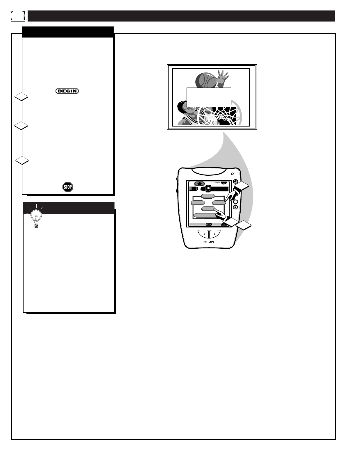
FEATURE MENU CONTROLS (CONTINUED)
D
o you ever have trouble
remembering on which
channel a particular station or
network is located? The Channel
Labels Control is a quick way to
view and select channels from a
list of Labeled channels.
A Label is a four letter callout you
can set to appear with the on
screen channel number. Example
Label: WXYZ - for a TV station's
call letters.
To select channels from the
Channel Labels Control:
With the FEATURES MENU
(3 of 5) on screen, move the RED
highlight with the MENU
buttons. Then press the MENU (or
ok) button to select CHANNEL
LABELS.
Press the MENU ▲▼ and
MENU (or ok) buttons
to
highlight and select either:
"MANUAL" to create your own
label for a channel.
"PRESETS" to choose from a list
of prewritten channel labels.
(See instruction details on this
page.)
Press the Exit button to clear
the screen.
CHANNEL LABELS
MANUAL- To create your
own Channel Label:
Press the Channel ▲▼ or
Number buttons to select
desired station.
A red highlight shows the
active letter space for the
channel label.
Press the outer MENU
▲▼ buttons on the remote
to pick any of the letters or
symbols that are given for
your use.
Press the outer MENU §
©
buttons on the remote to
move the red highlight to
the other letter spaces and
repeat.
Press the Exit button to
clear the screen when
finished.
1
2
3
PRESETS -To pick a Label
from the "LABEL" list:
Press the Channel ▲▼ or
Number buttons to select
desired station.
Press the outer MENU
▲▼ buttons to move up
and down the Channel
Label list.
Just stop on any label you
might want to use.
The selected label
automatically appears with
channel changes and when
the STATUS button is
pressed.
Press the Exit button to
clear the screen when
finished.
25
FEATURE MENU
CHANNEL
LABELS
LANGUAGE
SELECTION
EXIT
1
Menu
DN
ok
Exit
INFO
HDR PTV
Source
A/CH3/5
MORE...
3 OF 5
channel
1
mute
++
volume
++
CHANNEL LABELS
MANUAL
PRESETS
EXIT
Create Your Own
Choose From List
2
3
BRV
CHANNEL GUIDE LABEL
C H 1 0 C B S
ANTENNA A LABELS
or
to SELECT
or
to CHANGE
when FINISHED
M
Channel 1 0
CHOOSE ANTENNA A CHANNEL
M
CBN
CBS
CNBC
CMT
to SELECT LABEL
to EXIT

N
ote: If you went through First
Time Setup, This task has
already been completed for you.
For our Spanish and French
speaking TV owners an on-screen
LANGUAGE option is present.
With the LANGUAGE control you
can set the TV’s on-screen features
to be shown in either English,
Spanish or French.
Select the LANGUAGE
DISPLAY control.
With the FEATURES MENU (3
of 5) on screen, move the RED
highlight with the MENU
buttons. Then press the MENU (or
ok) button to select the feature.
Press the MENU▲▼ and
MENU (or ok) buttons to
highlight and select (U) English,
Español, or Francais on the display
control.
Text for the on-screen Menu will
change to the selected language.
Press the Exit button to clear
the screen.
LANGUAGE
1
2
3
Remember, the
Language control only
makes the TV’s on-screen
(MENU) items appear in English,
Spanish, or French text. It does not
change the other on-screen text
features such as Closed Captioned
(CC) TV shows.
SMART HELP
FEATURE MENU CONTROLS (CONTINUED)
26
1
3
MAIN MENU
PICTURE
FEATURES
1ST TIME SETUP
DN
Menu
Exit
INFO
HDR PTV
ok
Source
A/CH3/5
SOUND
EXIT
FEATURE MENU
ANALOG
FORMAT
CLOSED
CAPTIONS
EXIT
FEATURE MENU
SET
CLOCK
HALF HOUR
mute
channel
++
volume
++
1
2
REMINDER
EXIT
FEATURE MENU
CHANNEL
LABELS
LANGUAGE
SELECTION
CABLE
TUNING
CHANNEL
MEMORY
MORE...
1 OF 5
PARENTAL
CONTROL
CHANNEL
DISPLAY
MORE...
2 OF 5
EXIT
LANGUAGE SELECTION
ENGLISH
ESPANOL
FRANCAIS
EXIT
MORE...
MORE...
3 OF 5
HELP

T
he BASS BOOST control
increases the low frequency
audio range of the TV. This creates
a deeper, fuller playback sound
which can be heard through the
TV's speakers.
Select BASS BOOST sound
control.
With the SOUND MENU (1 of 3)
on screen, move the RED highlight
with the MENU buttons. Then
press the MENU (or ok) button to
select the feature.
Press the MENU ▲▼ and
MENU (or ok) buttons
to
highlight and turn ON (
U) the
BASS BOOST control.
Press the Exit button to clear
the screen.
BASS BOOST
1
2
3
SOUND MENU CONTROL ADJUSTMENTS
Y
our TV also has individual
sound adjustment controls. The
BASS (low frequency), TREBLE
(high frequency) , and Speaker
BALANCE may all be used to
adjust the sound playback of TV
programs.
Select BASS, or TREBLE, or
BALANCE sound control.
With the SOUND MENU (1 of 3)
on screen, move the RED highlight
with the MENU buttons. Then
press the MENU (or ok) button to
select the feature.
Press the MENU § © (Left
and Right) buttons to adjust the
sound control to levels you prefer.
Press the Exit button to clear
the screen.
BASS, TREBLE, BALANCE
1
2
3
Select “Next” and then press the MENU (M)
button to view and adjust additional Audio
controls. For Example: Treble, Balance, etc.
27
Note: Audio Menu controls can be set separately dependent upon the
current TV operating mode (NTSC/ANTENNA, AUX 4, AUX 5,
etc.). For instance, the TV Speaker On/Off control can be set to
“ON” for normal NTSC TV viewing playback operation; while the
same Audio control can also be set to “OFF” in a AUX 4 or AUX 5
Input Source mode.
1
3
MAIN MENU
PICTURE
FEATURES
1ST TIME SETUP
DN
Menu
Exit
INFO
HDR PTV
ok
A/CH3/5
Source
SOUND
EXIT
SOUND MENU
BASS TREBLE
BALANCE
INCREDIBLE SURROUND
EXIT
mute
channel
++
volume
++
1
2
MIN
EXIT
BASS BOOST
MORE...
1 OF 3
BASS
MAX
NEXT...
1
3
MAIN MENU
PICTURE
FEATURES
1ST TIME SETUP
DN
Menu
ok
Exit
INFO
HDR PTV
Source
A/CH3/5
SOUND
EXIT
1
mute
channel
volume
SOUND MENU
BASS TREBLE
BALANCE
INCREDIBLE SURROUND
EXIT
++
++
BASS BOOST
ON
OFF
EXIT
BASS BOOST
MORE...
1 OF 3
NEXT...
2

SOUND MENU CONTROLS (CONTINUED)
STEREO
Y
our TV is able to receive
broadcast stereo TV programs.
The TV is equipped with an
amplifier and twin speaker system
through which the stereo sound
can be heard.
Note: STEREO will appear on the
TV’s channel status screen to
indicate when a stereo broadcast
signal is available and received.
Select STEREO sound control.
With the SOUND MENU (2 of 3)
on screen, move the RED highlight
with the MENU buttons. Then
press the MENU (or ok) button to
select the feature.
Press the MENU ▲▼ and
MENU (or ok) buttons
to
highlight and turn ON (
U) the
STEREO mode.
Press the Exit button to clear
the screen.
t
o
d
a
y
'
s
a
n
d
f
o
r
n
e
w
s
a
n
d
t
o
d
a
y
'
s
a
n
d
f
o
r
n
e
w
s
a
n
d
SECOND AUDIO PROGRAM
EXIT
NORMAL SOUND
SECOND PROGRAM SOUND
SOUND MENU
SECOND AUDIO PROGRAM
EXIT
2 OF 3
TV SPEAKERS
MORE...
DISPLAY VOLUME
STEREO
SECOND PROGRAM SOUND CAN
ONLY BE SELECTED (
U) WHEN
SAP INFORMATION IS PRESENT
ON CURRENT CHANNEL.
1
2
3
Remember.
If a stereo signal is
not available and
the TV is placed in
the STEREO mode,
sound coming from
the TV will remain
monaural (mono).
SMART
HELP
Second Audio Program (SAP) is
part of the stereo broadcast
system. Sent as a additional
audio channel SAP can be heard
apart from the current TV
program sound. TV stations are
free to use SAP for any number
of purposes, but many experts
believe it will be used for foreign
language translations of TV
shows (or for weather and news
bulletins.)
NOTE: If a SAP signal is not
present with a selected program,
the SAP option can not be
selected. "This program does not
contain SAP information" will
show on the TV screen.
SECOND AUDIO PROGRAM
28
1ST TIME SETUP
1
3
MAIN MENU
PICTURE
FEATURES
DN
Menu
Exit
INFO
HDR PTV
ok
A/CH3/5
SOUND
Source
EXIT
SOUND MENU
BASS TREBLE
BALANCE
INCREDIBLE SURROUND
EXIT
mute
channel
++
volume
++
1
2
SOUND MENU
TV SPEAKERS
DISPLAY VOLUME
SECOND AUDIO PROGRAM
EXIT
BASS BOOST
MORE...
1 OF 3
STEREO
MORE...
2 OF 3
STEREO
MONO AT ALL TIMES
STEREO IF AVAILABLE
EXIT

SOUND MENU CONTROLS (CONTINUED)
T
he Incredible Surround control
can be used to add greater depth
and dimension to both monaural
(MONO) and STEREO TV sound.
Select the INCREDIBLE
SURROUND control.
With the SOUND MENU (2 of 3)
on screen, move the RED highlight
with the MENU buttons. Then
press the MENU (or ok) button to
select the feature.
Press the MENU ▲▼ and
MENU (or ok)
buttons to highlight
and turn ON (
U) the INCREDIBLE
SURROUND mode.
Press the Exit button to clear the
screen.
INCREDIBLE SURROUND
1
2
3
29
U
se the DISPLAY VOLUME
control to see the TV's volume
level settings on the TV screen.
Once set the Volume Display will
be seen each time the VOLUME
buttons (on the TV or remote) are
pressed.
Select DISPLAY VOLUME
control.
With the SOUND MENU (2 of 3)
on screen, move the RED highlight
with the MENU buttons. Then
press the MENU (or ok) button to
select the feature.
Press the MENU ▲▼ and
MENU (or ok)
buttons to
highlight and turn ON (
U) the
DISPLAY VOLUME control.
Press the Exit button to clear
the screen.
DISPLAY VOLUME
1
2
3
Remember,
"DURING
ADJUSTMENT"
means the volume
level will be on
screen whenever the
Volume buttons are
pressed.
SMART
HELP
1
3
MAIN MENU
PICTURE
FEATURES
1ST TIME SETUP
DN
Menu
ok
Exit
INFO
HDR PTV
Source
A/CH3/5
SOUND
EXIT
1
mute
channel
volume
SOUND MENU
BASS TREBLE
BALANCE
INCREDIBLE SURROUND
EXIT
++
++
INCREDIBLE SURROUND
ON
OFF
EXIT
BASS BOOST
MORE...
1 OF 3
NEXT...
2
1
3
MAIN MENU
PICTURE
FEATURES
1ST TIME SETUP
DN
Menu
Exit
INFO
HDR PTV
ok
Source
A/CH3/5
SOUND
EXIT
SOUND MENU
BASS TREBLE
BALANCE
INCREDIBLE SURROUND
EXIT
mute
channel
++
volume
++
1
2
SOUND MENU
TV SPEAKERS
DISPLAY VOLUME
SECOND AUDIO PROGRAM
EXIT
DISPLAY VOLUME
NEVER
DURING ADJUSTMENT
BASS BOOST
MORE...
1 OF 3
STEREO
MORE...
2 OF 3
EXIT

SOUND MENU CONTROLS (CONTINUED)
TV SPEAKERS
W
ould you like to hear TV
programs through your audio
hi-fi system? The PTV's Variable
Audio Output jacks and TV
Speaker On/Off control work
together to offer you this TV sound
option.
Connect the R(ight) and L(eft)
VARIABLE AUDIO OUT jacks
on the PTV to the R and L Audio
Input jacks on your amplifier or
sound system.
Set the audio system's volume to
normal listening level.
Turn the PTV and audio system
ON. You can now adjust the sound
level coming from the audio
system with the Volume ▲▼
buttons on the TV or remote.
To hear the TV sound from only
the audio system speakers, select
TV SPEAKERS control.
With the SOUND MENU (2 of 3)
on screen, move the RED highlight
with the MENU buttons. Then
press the MENU (or ok) button to
select the feature.
Press the MENU ▲▼ and
MENU (or ok) buttons
to
highlight and turn OFF (
U) the TV
SPEAKERS control.
You should now only hear TV
sound coming from the audio
system speakers.
Press the Exit button to clear
the screen.
1
2
3
4
5
BACK OF PTV
AUDIO SYSTEM
AUDIO IN
(RED/WHITE)
VARIABLE
AUDIO
OUTPUT JACKS
SMART HELP
Remember, the audio
system may have to be in
AUX(iliary) mode to play sound
from the TV (Outputs).
Note: When the TV SPEAKER
control is set to "NORMAL" (for
TV speaker operation) make sure
the VARIABLE AUDIO OUTPUT
control (see next page) is also set
to "STEREO" in order for the TV's
AUDIO OUTPUT jacks to work
properly.
30
NOTE: The TV’s FIXED
AUDIO OUTPUT jacks can
also be used for the playback
of TV program sound with an
external audio amplifier, or
home theater hi-fi system,
Connection of the FIXED
AUDIO OUT(puts) is similar
to the Variable Audio Outputs
(as shown above). However,
specific sound level
adjustments will be made with
the controls at the external
amplifier or home sound
system (instead of through the
TV’s audio level controls.)
NOTE: The TV’s PIP
AUDIO OUTPUT jacks can
also be used for additional
stereo playback options such
as wireless transmitter
headphone hook-up, or as an
external amplifier connection
source. However, with normal
PIP feature operations (when
the ANT A and ANT B Input
sources are connected for
use), the PIP AUDIO
OUTPUTs will switch from
stereo to monaural (mono)
sound. Stereo sound will only
be available with the TV’s
Main screen (or ANT A
supplied signal) at that time.
Note: Audio Menu controls can be set separately dependent upon the
current TV operating mode (NTSC/ANTENNA, AUX 4, AUX 5,
etc.). For instance, the TV Speaker On/Off control can be set to
“OFF” for normal NTSC TV viewing playback operation; while the
same TV Speaker Audio control can also be set to “ON” in a AUX 4
or AUX 5 Input Source mode.
SOUND MENU
TV SPEAKERS
DISPLAY VOLUME
SECOND AUDIO PROGRAM
EXIT
DN
4
3
5
Menu
Exit
INFO
HDR PTV
ok
Source
A/CH3/5
STEREO
MORE...
TV SPEAKERS
2 OF 3
NORMAL
TV SPEAKERS OFF
EXIT
channel
volume
3
1
R
mute
++
++
L
AUX/TV INPUT
PHONO INPUT
4
2
FIXED
VAR
PIP
AUDIO OUT
R
L
ANT A/CABLE
75 V UHF/VHF
VIDEO OUT
G-LINK

SOUND MENU CONTROLS (CONTINUED)
+
-
+-
SURROUND SOUND
B
y adding optional external
speakers to the PTV's sound
system, you can create the feeling
of reflected sound that surrounds
you at a movie theater or concert
hall.
Connect both external
speakers to the speaker wire
terminals on the PTV.
Recommended speakers: 8 ohm, 15
watt minimum. Be sure the (+) and
(-) speaker wires are connected to
the correct R(ight) and L(eft)
speaker terminals on the TV.
Place the speakers so the
viewing area is between the PTV
and the rear surround speakers.
(See overhead view drawing.)
Turn PTV ON and place the
STEREO control to the "STEREO
IF AVAILABLE" (
U) position.
After setup whenever a stereo
signal is received the audio will be
heard in Surround Sound.
1
2
3
BACK OF PTV
REAR SURROUND SOUND SPEAKERS
Note: The rear Surround Sound speakers will not
be heard at the same volume level as the front TV
speakers. It is intended for the rear speakers to
give a background noise effect which requires a
lower volume level than the TV's front speakers.
2
PRIMARY VIEWING AREA
PTV
REAR SPEAKER
REAR SPEAKER
VARIABLE AUDIO OUTPUT
T
he PTV's Variable Audio
Output jacks can also be used
for Surround Sound. Once they are
connected to an external hi-fi
system its speakers can be used for
the playback of Surround Sound.
Connect the R(ight) and L(eft)
VARIABLE AUDIO OUT jacks
on the PTV to the R and L Audio
Input jacks on your amplifier or
sound system.
Turn PTV ON and place the
VARIABLE AUDIO OUTPUT on
screen control to the SURROUND
(
U) position. (Sound Menu 3 of 3).
Note:This will change the
Left/Right channel audio line level
signal at the Audio Output jacks to
the same signal found at the PTV's
Surround Sound Speaker terminals.
1
2
AUDIO SYSTEM SPEAKERS USED AS REAR
SURROUND SOUND SPEAKERS
BACK OF PTV
REAR SURROUND SOUND
SPEAKER TERMINALS
VARIABLE AUDIO
OUTPUT JACKS
AUDIO
INPUT JACKS
Remember,
Surround Sound
will not work with
only one speaker
connected; or with
monaural audio
material (unless
Variable Audio
Surround control is
turned ON - see
section below).
SMART
HELP
31
SUBWOOFER
SUBWOOFER OUTPUT
Use the Subwoofer Output (RCA
plug connector) to send the
subwoofer audio channel signal (at
line level) to an optional external
powered Subwoofer speaker. The
Subwoofer audio signal is for the
playback of only the lowest
frequency notes (under 100 Hz).
SOUND MENU
VARIABLE AUDIO OUTPUT
1
EXIT
MORE...
VARIABLE AUDIO OUTPUT
3 OF 3
STEREO
SURROUND
EXIT
DN
2
Menu
ok
Exit
INFO
HDR PTV
Source
A/CH3/5
mute
channel
++
volume
++
2
R
AUX/TV INPUT
PHONO INPUT
L

OPTIONAL SURROUND SOUND CONNECTIONS
E
xtra speaker connections have
been supplied on the rear of
the PTV. These extra connections
are especially important for some
of the optional Amplifier and multispeaker arrangements that are
possible with Dolby Pro Logic
Surround Sound audio features.
For example: With the Surround
mode multiple speakers are needed
to complete the setup for proper
DOLBY SURROUND sound
playback-
2 Front Left/Right Speakers
1 Center Channel Speaker
2 Rear Surround Speakers
The Front Left/Right, Center, and
Rear Surround Speakers have their
signals supplied by the connections
located on the back of the Dolby
ProLogic Audio Receiver.
Note: A CENTER CHANNEL
AMP(plifier) INPUT is also
located on the PTV. This input can
be used to connect the external
Audio Receiver's Center Channel
Output in order to play Center
Channel sound through the internal
PTV speakers.
When an Audio Receiver is used as
the audio source for the CENTER
CHANNEL AMP INPUT:
• Place the PTV's AMP SWITCH
to the EXTERNAL position
REAR OF PTV
TV’S INTERNAL SPEAKERS
USED FOR SURROUND SOUND
CENTER CHANNEL
32
DOLBY PROLOGIC
AUDIO AMPLIFIER
LEFT FRONT
SPEAKER
RIGHT FRONT
SPEAKER
REAR SURROUND
SPEAKERS
SURROUND
SPEAKERS
+ R -
- L +
CENTR CH
OUT
+
AMP SWITCH
EXT
MAXIMUM 30 WATT INPUT TO SPEAKERS
EXT CENTER CHANNEL AMP INPUT
-
INT
+-
+
-

USING THE AUDIO/VIDEO INPUT JACKS
ANTENNA
OUT
IN
OUT
IN
AUDIO R
L
VIDEO
IN
OUT
1
2
DN
ANT A
AUX 1 DVD VIDEO
AUX 2 VIDEO
AUX 2 Y P
B PR
AUX 3 VIDEO
ANT B
AUX 1 DVD Y P
B PR
AUX 4 HD Y P
B PR
AUX 5 HD RGB-VGA
5
++
++
mute
volume
channel
ok
Exit
Menu
HDR PTV
INFO
A/CH3/5
Source
4
4
3
T
he PTV's Audio/Video Input
jacks are for direct picture and
sound connections between the TV
and a DVD (or VCR, etc.) that has
Audio/Video (Composite) Output
jacks.
To view the playback of a DVD
program disc by using the
Audio/Video Input jacks on the TV:
Connect the VIDEO OUT jack
from the DVD to the AUX 1
VIDEO IN jack on the PTV.
Connect the AUDIO OUT
jacks R(ight) and L(eft) from the
DVD to the AUX 1 AUDIO IN
jacks on the PTV.
Select the “AUX 1 DVD
VIDEO” Picture Source control
on the PTV.
Press the Source button on the
Pronto remote (or on the front of
the PTV) to display the Input
Source control screen.
Press the MENU ▲▼ and
MENU (or ok) buttons
to
highlight and select (
U) the AUX
1 DVD VIDEO mode.
Turn the DVD ON and press
PLAY to view the playback disc
on the PTV.
AUX 1 VIDEO INPUTS
1
2
3
4
BACK OF PTV
VIDEO IN
(YELLOW)
AUDIO IN
(RED/WHITE)
DVD
PICTURE AND SOUND FROM
PLAYBACK OF DVD
SMART HELP
Remember, if you have
need for any connecting
cables or devices contact your
dealer or our Parts Information
center (1-800-851-8885) to order
any optional accessories.
5
AUDIO/VIDEO
OUTPUT JACKS
ON DVD
NOTE: Connections and use of the
PTV's rear AUX 2 VIDEO Input jacks
are the same as for the AUX 1 jacks
(except “AUX 2 VIDEO” is selected as
the Picture Source in step 3).
33

USING THE AUDIO/VIDEO INPUT JACKS (CONTINUED)
SOURCE EXIT
UP
CH
CH
DOWN
+
VOL
VOL
–
M
ANT A
AUX 1 DVD VIDEO
AUX 2 VIDEO
AUX 2 Y P
B PR
AUX 3 VIDEO
ANT B
AUX 1 DVD Y P
B PR
AUX 4 HD Y P
B PR
AUX 5 HD RGB-VGA
5
DN
++
++
mute
volume
channel
ok
Exit
Menu
HDR PTV
INFO
A/CH3/5
Source
4
4
3
AUX3
VIDEO IN
L
AUDIO IN
R
S-VIDEO IN
1
2
F
or more convenient Direct
playback connections the
PTV's Side Video (AUX 3) Input
panel can be used. Located on the
PTV's right side panel (angled
toward the front for easy access)
these Audio/Video Input jacks
allow for quick connections,
particularly for the playback of
Camcorder tape recordings.
To view the playback of a
Camcorder recording using the
Audio/Video Input jacks on the
side of the PTV:
Connect the VIDEO OUT jack
from the Camcorder to the VIDEO
IN jack on the side of the PTV.
Connect the AUDIO OUT
jacks R(ight) and L(eft) from the
Camcorder to the AUDIO IN jacks
on the side of the PTV.
Select the "AUX 3 VIDEO"
Picture Source control on the TV.
Press the Source button on the
Pronto remote (or on the front of
the PTV) to display the Input
Source control screen.
Press the MENU ▲▼ and
MENU (or ok)
buttons to
highlight and select (
U) the AUX
3 VIDEO mode.
Turn the Camcorder ON and
press PLAY to view the tape on
the PTV.
AUX 3 VIDEO INPUTS
1
2
3
4
SIDE PANEL AUDIO/VIDEO
INPUT JACKS
(S-VIDEO Input plug also provided
for possible S-VHS tape playback
material.)
VIDEO IN
(YELLOW)
AUDIO IN
(RED/WHITE)
CAMCORDER
PICTURE AND SOUND FROM PLAYBACK
OF CAMCORDER TAPE
5
AUDIO/VIDEO
OUTPUT JACKS
ON CAMCORDER
SMART HELP
Remember, if you have a
single (monaural) Audio
Output Camcorder, "Y" connectors
are available to completeyour
connection. Contact your dealer or
our Parts Information center (1800-851-8885) to order any
optional accessories.
34

USING THE AUDIO/VIDEO INPUT JACKS (CONTINUED)
T
he S(uper)-Video connection on
the rear (and Side Panel) of the
PTV can give you better picture
detail and clarity for the playback of
S-VHS VCR tapes or DVDs than the
normal antenna (RF Signal) or
Video (Composite) picture
connections.
Note: The VCR or DVD Player)
must have a S-VIDEO OUT(put)
jack in order for you to complete the
connections shown on this page.
Connect the S-VIDEO (S-
VHS) OUT jack from the VCR to
the S-VIDEO AUX 1 IN(put) jack
on the PTV.
The S-VIDEO connecting cable
will be supplied with the S-VHS
VCR (or DVD Player).
Connect the AUDIO OUT
jacks R(ight) and L(eft) from the
VCR to the AUDIO AUX 1
IN(put) jacks on the PTV.
Select the "AUX 1 S-VIDEO"
Picture Source control.
Press the Source button on the
Pronto remote (or on the front of
the PTV) to display the Input
Source control screen.
The "AUX 1 S-VIDEO" picture
source option appears only when a
S-VIDEO cable has been connected
to the PTV’s AUX 1 IN(puts).
Press the MENU ▲▼ and
MENU (or ok)
buttons to highlight
and select (
U) the AUX 1
S-VIDEO mode.
Turn the VCR ON and place it
in the S-VIDEO (or S-VHS)
playback mode. Insert S-VHS
cassette tape and playback in a
normal manner.
AUX 1 - S-VIDEO INPUTS
1
2
3
4
S-VHS VCR
AUDIO OUT
(RED/WHITE)
S-VIDEO OUT
BACK OF PTV
PICTURE AND SOUND FROM
PLAYBACK OF S-VHS VCR TAPE
S-VIDEO
CABLE
NOTE: A CD-i (Compact Disc Interactive)
player, Video Game, or other S-VIDEO
accessory can be hooked up to the PTV using
this type of connection. Please be aware that
such video sources, which show a constant
non-moving pattern on the screen, can cause
picture tube damage. When not in use turn
your video accessories OFF. Also, regularly
alternate the use of video sources with normal
TV viewing.
NOTE: Connections and use of the PTV's
AUX 2 and AUX 3 S-VIDEO Input jacks are
the same as for the AUX 1 S-VIDEO jacks
(except “AUX 2 or AUX 3 S-VIDEO” is
selected as the Picture Source in step 3).
35
5
ANT A
ANT B
AUX 1 S-VIDEO
AUX 1 DVD Y P
AUX 2 VIDEO
AUX 2 Y P
AUX 3 VIDEO
AUX 4 HD Y P
AUX 5 HD RGB-VGA
DN
B PR
B PR
B PR
4
HDR PTV
INFO
Source
ok
A/CH3/5
Menu
Exit
1
2
AUDIO
OUT
R
IN
OUT
OUT
OUT
S-VIDEO
ANTENNA
mute
3
channel
volume
++
++
5
4
VIDEO
L
IN
IN

USING THE AUDIO/VIDEO INPUT JACKS (CONTINUED)
FIXED
1
2
OUT
AUDIO
R
L
S-VIDEO
OUT
VIDEO OUT
Y
P
P
B
R
VIDEO 1
VIDEO 2
OUT
5
4
DN
ANT A
AUX 1 DVD VIDEO
AUX 2 VIDEO
AUX 2 Y P
B PR
AUX 3 VIDEO
ANT B
AUX 1 DVD Y P
B PR
AUX 4 HD Y P
B PR
AUX 5 HD RGB-VGA
++
++
mute
volume
channel
ok
Exit
Menu
HDR PTV
INFO
A/CH3/5
Source
4
4
3
C
omponent Video Inputs
provide for the highest
possible color and picture
resolution in the playback of
digital signal source material such
as with DVD players. The color
difference signals (PB, PR) and the
luminance (Y) signal are
connected and received separately
which permits for improved color
bandwidth information (not
possible when using composite
video or S-Video connections).
Connect the Component (Y PB
PR) VIDEO OUT jacks from the
DVD player to the (Y PB PR)
VIDEO IN(put) jacks on the PTV.
Connect the AUDIO OUT
jacks R(ight) and L(eft) from the
DVD player to the AUX 1 AUDIO
IN jacks on the P TV.
Select the "AUX 1 Y PB PR"
Picture Source control on the TV.
Press the Source button on the
Pronto remote (or on the front of
the PTV) to display the Input
Source control screen.
Press the MENU ▲▼ and
MENU (or ok)
buttons to
highlight and select (
U) the AUX
1 Y P
B PR mode.
Turn the DVD player ON and
press PLAY to view the source
material playback on the TV.
COMPONENT VIDEO INPUTS
1
2
3
4
COMPONENT
VIDEO OUTPUTS
AUDIO OUT (L/R)
(RED/WHITE)
Optional Video/Audio Cables (with standard
RCA plug connectors) are available to
complete your Component Input Jack
connections. Contact your dealer, or our Parts
Information Center (1-800-851-8885) to order
any optional accessories.
DVD PLAYER
(equipped with Component Color
& Luminance Outputs)
PICTURE AND SOUND FROM PLAYBACK
OF DVD SOURCE MATERIAL
5
SMART HELP
The description for the
component video connectors
may differ depending on the
DVD player or accessory digital source
equipment used (e.g. Y PB PR; R-Y/BY/Y; Cr/Cb/Y, etc.). Although
abbreviations and terms may vary, the
letters “B” and “R” stand for the blue
and red color component signal
connectors, and “Y” indicates the
luminance signal. Refer to your DVD
or digital accessory Owner’s Manual
for definitions and connection details.
36
BACK OF PTV
NOTE: Connections and use of the PTV's rear AUX 2 Y P
B
PR Input jacks are the same as for the AUX 1 jacks (except
"AUX 2" Y PB PR is selected as the Picture Source in step 3).

USING THE AUDIO/VIDEO OUTPUT JACKS (CONTINUED)
ANTENNA
OUT
IN
OUT
IN
AUDIO
R L
VIDEO
IN
OUT
1
2
5
ANT A
AUX 1 DVD VIDEO
AUX 2 VIDEO
AUX 2 Y P
B PR
AUX 3 VIDEO
ANT B
AUX 1 DVD Y P
B PR
AUX 4 HD Y P
B PR
AUX 5 HD RGB-VGA
++
++
mute
volume
channel
ok
Exit
Menu
HDR PTV
INFO
A/CH3/5
Source
3
3
INFO
A/CH2/5
Status
Surf
+100
HDR PTV
4
3
AUDIO/VIDEO OUTPUTS
T
he Audio/Video Output jacks
on the PTV can be used to
record TV programs on VCRs
which have Audio/Video Input
jacks.
To record TV programs by using
the Audio/Video jacks on the PTV:
Connect the VIDEO OUT jack
from the PTV to the VIDEO IN
jack on the VCR.
Connect the AUDIO OUT
jacks R(ight) and L(eft) from the
PTV to the AUDIO IN jacks on the
VCR.
Select the "ANTENNA A"
Picture Source control on the TV.
Press the Source button on the
Pronto remote (or on the front of
the PTV) to display the Input
Source control screen.
Press the MENU ▲▼ and
MENU (or ok)
buttons to
highlight and select (
U) the
ANTENNA A mode.
Select the channel on the PTV
that you want to record.
Turn the VCR ON. Put a
cassette tape in the unit and place
the VCR in the RECORD mode.
1
2
3
4
BACK OF PTV
VIDEO OUT
(YELLOW)
VCR
PICTURE AND SOUND BEING RECORDED
ON VCR.
AUDIO/VIDEO INPUT
JACKS ON VCR
AUDIO
OUT
(RED/
WHITE)
SMART HELP
Remember, If the VCR
has an INPUT SELECTOR
switch, place it in the LINE or
CAMERA position.
Unattended Timer Recordings
with a VCR are possible, but not
recommended with this
connection since the TV must be
left ON for the VCR to record.
37
5

MONITOR FEATURES MENU CONTROLS
VGA/RGB/HDCOMPONENT
38
BRIGHTNESS
A
nother function with your PTV
is for the connection and use
of Personal Computers (PCs), and
other High Definition (HD) digital
source equipment (through the use
TV’s Monitor inputs and display
mode). Dedicated HD Audio Input
jacks (located on the rear of the
PTV) are also paired to the
external source Monitor Video
Inputs (VGA and HD Component
Video In) for audio playback
connections as well.
For example: To connect a Philips
DVX8000 Multimedia Home
Theater (MMHT) for monitor
mode display use on the PTV:
Connect a 15 pin VGA signal
cable (optional) from the VGA
(or SVGA) jack on the select
auxiliary equipment (example:
DVX8000 MMHT) to the VGA
Input jack on the PTV.
Connect the Left/Right HD
INPUT AUDIO IN jacks on the
PTV to the (L/R) Audio Output
jacks (labeled Front) on the
DVX8000 MMHT.
Press the Source button on the
Pronto remote (or on the front of
the PTV) to select the AUX 5 HD
RGB/VGA Monitor Input mode.
Press the MENU ▲▼ and
MENU (or ok)
buttons to
highlight and select (
U) the AUX
5 HD RGB/VGA mode.
Use the DVX8000 MMHT as
the video (and/or audio) playback
source for material to be displayed
on the PTV’s screen.
1
2
3
4
REAR OF PTV
REAR OF DVX8000 MMHT
15 PIN VGA
Connection Cable
Left/Right
Audio IN
HD COMPONENT VIDEO IN
R
L
• Separate Red/Green/Blue (Luminance-Y and
Color Difference-Pr/Pb) Component Video
Inputs provide for improved color bandwidth
information and highest possible picture
resolution for digital source connections.
• H/H + V (for combined Horizontal/Vertical sync
signals) or V(ertical) sync inputs control the
display of a RBG sourced picture in the left-toright dimension and from top-to-bottom.
Note: The PTV will
display any Television
compatible VGA or
SVGA (60Hz only)
signal input.
SMART HELP
Note: The PTV’s video
display may temporarily appear
misconverged during the
initialization of certain VGA input
connected PC programs (i.e., DOS).
Once the PC program has completed its
“bootup” phase, normal signal level
processing will reoccur and the PTV
display will return to normal.
REAR OF PTV
PICTURE
SHARPNESS
SVM OFF
COLOR
TINT
VOLUME BAR ON
3
ANT A
ANT B
AUX 1 DVD VIDEO
AUX 1 DVD Y P
AUX 2 VIDEO
AUX 2 Y P
AUX 3 VIDEO
AUX 4 HD Y P
AUX 5 HD RGB-VGA
Menu
Exit
B PR
B PR
B PR
UP
CH
+
VOL
M
SOURCE EXIT
VOL
–
CH
DOWN
HDR PTV
Source
ok
INFO
A/CH3/5
1
L
2
VIDEO
MULTI REMOTE
FM
AM
GND
LD VCR 2 IN-VCR-OUT
DSS
mute
3
channel
++
volume
++
3
ANTENNA
L
R
CD
IN-TAPE-OUT DSSLDVCR 2
ON
OFF
IN-VCR-OUT
MULTI
USB
IN
TV
OUT
MONT
AC-3 RF
AC-3/
PCM
COAX
AC-3/PCM
OPT
IN
IN
2
1
AUDIO OUTPUT
SUB
L
WOOFER
CENTER
R
CENTERSURROUNDFRONT
TV
PHONE
TV/CABLE
ANT
RGB
SVGA
LINE
R DATA
(RGB)
MIC
IR
LINE IN

MONITOR FEATURES MENU CONTROLS
MONITOR MENU CONTROLS
39
T
he Monitor Menu feature
controls are to aid you in
setting up the PTV for the best in
display image quality. Generally,
the Monitor feature controls cover
the basics in color and video
image screen adjustments. A
variety of Monitor Audio Input
controls are also available for
various PTV speaker sound
adjustments. (See the Audio
Adjustments note to the right for
further details on AUX(iliary) and
NTSC/Antenna mode sound
controls.
Press the Source button on the
Pronto remote (or on the front of
the PTV) to select the desired High
Definition (HD) display mode
(AUX 4 HD Y PB PR; or AUX 5
HD RGB-VGA).
Press the MENU (or ok)
buttons to display the Main Menu
controls for the Monitor Mode.
Press the MENU buttons
to choose any of the individual
controls you wish to adjust for the
selected HD mode. Then press the
Menu (or ok) button to select the
highlighted control.
Also, use the Menu and Menu
(or ok) buttons to adjust the
selected control.
Press the Exit button on the
remote to clear the screen after you
have finished with all of your
feature control adjustments.
1
2
3
4
• Use the Brightness and other
Monitor picture features (such as
Picture, Sharpness, etc.) to adjust
overall screen intensity for
optimum light/dark screen areas
and shading details.
• Turn the Volume Bar Sound
Menu control ON to display the
volume level settings for external
audio sourced material on the
screen.
• Select the Bass/Treble/Balance
Sound Menu controls to adjust
low/high frequency sound and
speaker balance for external input
audio source material played
through the PTV’s audio system.
• Use the Display Mode and
Format Feature Menu controls
to set the PTV for the type of
external monitor display mode
source (VGA, AUTO, SVGA,
EXT HD); and the display
screen format used (PC,
NORMAL, WIDESCREEN).
• Additional Sync Type,
Horizontal Phase, Back Porch
(BP) Width Feature Menu
controls can be used to adjust for
color shifts, black level, and
various other display screen
imagery.
• Use the LANGUAGE control to
set the HD Menu control screens
for English, Spanish (Espanol), or
French (Francais) language term
displays.
• Note: The list of Monitor Menu features (and their individual
control settings) will change or readjust according to the
capabilities of the selected Display Mode (AUX 4, AUX 5, etc.) .
SMART HELP
Certain barscale Monitor
Feature Menu adjustments
(such as Brightness, Picture, etc.)
will display separate control panel
screens for individual settings.
Repress the Menu button (on the
remote or local keyboard) to return
the PTV to the Monitor Menu
when control adjustments are
complete.
Note: Audio Menu controls can be set separately
dependent upon the current TV operating mode
(NTSC/ANTENNA, AUX 4, AUX 5, etc.). For
instance, the TV Speaker On/Off control can be set to
“ON” for normal NTSC TV viewing playback
operation; while the same Audio control can also be set
to “OFF” in a AUX 4 or AUX 5 Input Source mode.
BRIGHTNESS
PICTURE
SHARPNESS
SVM OFF
COLOR
TINT
VOLUME BAR ON
BRIGHTNESS
PICTURE
MAIN MENU
PICTURE
SOUND
FEATURE
EXIT
3
2
HDR PTV
Menu
Exit
Source
ok
INFO
A/CH3/5
mute
1
channel
++
volume
++
2
3
SHARPNESS
COLOR
TINT
COLOR TEMP
BACK
BASS
TREBLE
BALANCE
BASS BOOST ON
INCR SURROUND ON
STEREO STEREO
MORE....
4
(OR OFF)
(OR OFF)
(OR MONO)
AUTO SOUND ON
TV SPEAKERS NORMAL
VAR AUDIO OUT STEREO
VOLUME BAR ON
BACK
DISPLAY MODE VGA
DISPLAY FORMAT PC
SYNC TYPE AUTO
HOR PHASE
BP WIDTH
LANGUAGE ENGLISH
BACK
(OR OFF)
(OR OFF)
(OR SURROUND)
(OR OFF)
(OR SVGA/AUTO/HD)
(OR NORMAL)
(OR MODE 1-4)
(OR ESPANOL/FRANCAIS

W
ith Auto Picture you can set a
number of video and audio
controls to your own personal
preference. Once the individual
controls have been adjusted to the
levels you desire, use the list of Auto
Picture feature category titles to
quickly reselect these “personalized”
settings contained within the memory
of the PTV. (See the next page for
more details on the labeling options
and use of Auto Picture.)
Press the AUTO button on the
Pronto remote (touchscreen 1 of 5).
Press the MENU (or ok) button
(Pronto remote touchscreen 3 of 5) to
select the Auto Picture feature
highlighted in RED.
Press the MENU ▲▼ buttons to
highlight the category list for Auto
Picture. Press the MENU (or ok)
button to select (
U) the desired title.
Press the MENU buttons to
choose any of the individual controls
you wish to adjust for the Auto
Picture selected title. Then press the
Menu (or ok) button to select the
highlighted control.
Press the Menu and Menu
(or ok) buttons to adjust the selected
control.
Press the Exit button on the
remote to clear the screen after you
have finished with all of your Auto
Picture feature control adjustments.
1
2
3
REMOTE CONTROL OPERATION
4
AUTO PICTURE
40
SMART HELP
Note: Select the
“FACTORY SETTINGS”
category to automatically return the
TV to the video and audio control
levels preset at the factory prior to
product shipment.
5
1
AUTO MENU
AUTO
PICTURE
AUTO
SURF
EXIT
Auto
Analog Format
2
3
4
INFO
HDR PTV
Power
Sleep
A/CH1/5
5
Status
Menu
Exit
INFO
AUTO
SOUND
mute
channel
++
volume
++
HDR PTV
ok
Source
A/CH3/5
2
3
4
AUTO PICTURE
SPORTS
MOVIES
WEAK SIGNAL
CARTOONS
CUSTOM
FACTORY SETTINGS
M to SELECT
EXIT
AUTO PICTURE MENU
CHANGE LABEL
ANALOG FORMAT
BRIGHT
EXIT
AUTO PICTURE MENU
SHARP
FLESH CORRECTION
BASS
EXIT
COLOR
TINT
PICTURE
MORE...
1 OF 3
CLEARVIEW
SAP
TREBLE
MORE...
2 OF 3
AUTO PICTURE MENU
BALANCE
BASS BOOST
STEREO
INC. SURR
EXIT
VID ENHANCE
COLOR TEMP
MORE...
3 OF 3

F
ollowing your initial setup
adjustments (see previous page),
just select the desired Auto Picture
category in order to place the PTV to
the personalized set of audio and
video control settings for that title.
Press the AUTO button on the
Pronto remote (touchscreen 1 of 5)..
Then press the MENU (or ok) button
(Pronto remote touchscreen 3 of 5) to
select the AUTO PICTURE control
feature.
Press the MENU ▲▼ buttons
with the list of “AUTO PICTURE”
categories on the TV screen to
highlight the desired category. Then
press the Menu (or ok) button to
select the audio and video control
settings for that particular title.
Press the Exit button on the
remote to clear the screen.
1
2
3
AUTO PICTURE
REMOTE CONTROL OPERATION (CONTINUED)
T
he "CHANGE LABEL" control
can be used to change the title of
a AUTO PICTURE setting into a
name or label that may be easier for
you to remember.
With the AUTO PICTURE
“CHANGE LABEL" control on the
screen, press the MENU ▲▼
buttons to spell out a new label or
title for the selected AUTO
PICTURE category.
Press the MENU § © buttons to
move the red highlight to each letter
space.
Press the Exit button to clear the
screen when the new label is finished.
1
2
3
CHANGE LABEL
AUTO PICTURE LABEL
when FINISHED
to SELECT
M
M Y O W N
to CHANGE
or
or
TINT
AUTO PICTURE MENU
PICTURE
EXIT
1 OF 3
COLOR
MORE...
BRIGHT
CHANGE LABEL
ANALOG FORMAT
++
++
mute
volume
channel
ok
Exit
Menu
HDR PTV
INFO
A/CH3/5
Source
3
1
2
41
AUTO MENU
AUTO
PICTURE
AUTO
SURF
EXIT
AUTO
SOUND
SMART PICTURE
SPORTS
MOVIES
WEAK SIGNAL
CARTOONS
CUSTOM
FACTORY SETTINGS
M to SELECT
1
Auto
2
HDR PTV
Power
Status
Sleep
Analog Format
INFO
A/CH1/5
1
3
Menu
Exit
INFO
mute
channel
++
volume
++
HDR PTV
ok
A/CH3/5
EXIT
Source
1
2

REMOTE CONTROL OPERATION (CONTINUED)
42
A
re you tired of the sound of
commercials following you
throughout the house? Auto Sound
allows you to preset a desired
volume level that the PTV sound will
not go above. This makes for an
even, more consistent sound by
reducing the “peaks” and “valleys”
that can occur during commercials.
Press the AUTO button on the
Pronto remote (touchscreen 1 of
5).
With the AUTO Menu on
screen, move the RED highlight
with the MENU buttons
(Pronto touchscreen 3 of 5). Then
press the MENU (or ok) button to
select the highlighted Auto Sound
control.
Press the Menu ▲▼ and the
Menu (or ok)
buttons to turn the
Auto Sound control ON (or OFF.)
Press the Exit button to clear the
screen when completed.
1
2
3
AUTO SOUND
4
Remember, Auto Sound
works for sound levels
coming from either the
Antenna/Cable input on the rear of
the PTV (RF audio); or the
Auxiliary (VCR/AUX IN) audio
inputs.
When using a Cable Converter
Box with the Auto Sound Control
ON, the TV’s volume level may
take up to ten seconds to gradually
increase to normal listening levels
(when the TV’s first turned on).
This is considered NORMAL with
various Cable Converter Box use.
SMART HELP
AUTO PICTURE
AUTO
PICTURE
AUTO
SURF
EXIT
1
Power
Auto
Sleep
Analog Format
INFO
2
3
4
HDR PTV
Status
Menu
A/CH1/5
Exit
AUTO
SOUND
INFO
mute
channel
++
volume
++
HDR PTV
ok
A/CH3/5
Source
AUTO SOUND
ON
✓
OFF
EXIT
2
3

REMOTE CONTROL OPERATION (CONTINUED)
A
“list” or series of previously
viewed channels can be selected
with the SURF button on your remote
control. With this feature you can
easily switch between different TV
programs that currently interest you.
The Auto Surf control allows you to
set up to 10 channels in its quick
viewing “list”.
Press the AUTO button on the
Pronto remote (touchscreen 1 of 5).
With the AUTO Menu on
screen, move the RED highlight with
the MENU buttons (Pronto
touchscreen 3 of 5). Then press the
MENU (or ok) button to select the
highlighted Auto Surf control.
Press the Menu ▲▼ then the
Menu (or ok)
button to select either
Auto Surf or 2-Channel Surf. (See
explanation of Surf options with the
illustration on this page.)
Press Exit button on the remote
control to clear the screen.
1
2
3
2-CHANNEL SURF/AUTO SURF
2 CHANNEL SURF- Current and
one previous channel in the ring.
AUTO SURF - Current and up to
nine additional channels available in
the ring. Note: The Channel Surf
ring can be used with fewer than ten
channels. In this way, the number of
Surf channels can match or fit your
present viewing interests.
4
With the Auto Surf control ON
(see above), select a desired
channel for viewing. You can use
the number buttons on the remote (or
the Channel ▲▼ buttons).
Press the SURF button on the
remote (Pronto touchscreen 2 of 5).
Some channel numbers may already
appear within the Surf channel list.
Press the Menu (or ok) button
(Pronto touchscreen 3 of 5) to
"ADD" the selected channel to the
Surf list.
Select the next desired channel and
repeat steps 2 and 3. Continue until
all desired channels are on the Surf
list.
Press the SURF button on the
remote to quickly review current
action on channels contained within
the Surf list.
To Use 2Channel Surf:
With the 2-Channel
Surf control ON,
select the two desired
channels for viewing
with the number
buttons on the remote
control (Pronto
touchscreen 2 of 5).
Then press the SURF
button on the remote
(touchscreen 2 of 5) to
"toggle" between the
two selected channels.
SMART
HELP
HOW TO USE AUTO SURF
1
2
3
4
Note: To Delete a channel from
the Surf list just press the SURF
button to select the desired
channel. Then press the Menu
(or ok) button and the channel
will be immediately dropped
from the on screen Surf list.
43
1
AUTO PICTURE
AUTO
PICTURE
AUTO
SURF
EXIT
Power
Auto
Sleep
Analog Format
INFO
2
3
4
HDR PTV
Status
Menu
A/CH1/5
Exit
AUTO
SOUND
AUTO SURF
AUT O S U R F
✓
2-C H A N N E L S U R F
mute
channel
++
volume
++
HDR PTV
ok
Source
EXIT
INFO
A/CH3/5
2
3
SURF
3
8
10
14
18
M to ADD
6 to List
1
+100
INFO
Status
3
HDR PTV
Surf
A/CH2/5
Menu
Exit
SURF
3
8
10
14
18
6
M to DELETE
6 to List
mute
channel
++
volume
++
2
HDR PTV
Source
ok
INFO
A/CH3/5
SURF
3
8
10
14
18
6
SURF
3
8
10
M to DELETE
14
3 to List
18
6
M to DELETE
3
6 to List
SURF
3
8
10
14
18
6
M to DELETE
10 to List

1
2
HOW TO USE THE PICTURE-IN-PICTURE (PIP) FEATURE
P
icture-in-Picture (PIP) is the
showing of two pictures on the
TV screen at the same time. (One
main screen picture and one small
inset picture - or PIP). For your
ease and convenience this PTV
has two separate inputs
(ANTenna A and ANTenna B) for
your home’s Antenna and/or
Cable TV system signal.
The ANT A input is primarily for
the TV’s main screen picture.
The ANT B input is provided as a
second, dedicated source option
for the PTV’s PIP “window” and
its feature operations. The signal
connected to the ANT B input can
be either a Split Signal Input (as
described in the section on this
page), or another type of external
signal source (such as a satellite
dish system, additional home
antenna, video accessory, etc.).
See the following steps on how
channels connected to the
ANT(enna) B Input can be shown
and used within the PIP window:
Connect your Antenna or
Cable TV
signal to the single 75
ohm INPUT plug on a two-way
Signal Splitter (not supplied).
Connect two lengths of RF
Coaxial Cable (F-type connectors
on both ends) to the two OUTPUT
plugs on the two-way Signal
Splitter.
Connect the twin OUTPUT
plugs on the Signal Splitter to the
ANT A and ANT B Inputs on the
rear of the PTV.
continue to next page
2
1
- PIP WINDOW -
Display signal supplied
primarily through ANT
B Input on rear of TV.
BACK OF TV
SMART HELP
For other possible PIP
connections see page 49 for
the "More PIP Connections"
section.
If you need any accessories or
parts to complete the described
PIP connections, contact your
dealer, or our Parts Information
Center at (1-800-851-8885) for
details.
See the Set-Up Guide also provided with
your TV set for further Cable TV connection
options and accessories.
SOURCE EXIT
UP
CH
CH
DOWN
+
VOL
VOL
–
M
- MAIN SCREEN -
Display signal supplied
primarily through
ANT A Input on rear
of TV.
Round Cable
75(Ω) Ohm
Cable TV
Company
Cable TV Signal
300 to 75Ω Adapter
(483521827003)
Twin Lead
Wire
Round Cable
75(Ω) Ohm
- Outdoor or Indoor Antenna -
receives normal broadcast channels
2-13 (VHF) and 14-69 (UHF).
OR
Note: The purpose of the ANT B input is to
provide an easily connected, dedicated picture
source for PIP feature use. Other signal source
options (such as a satellite dish system, additional
external antenna, VCR, or Video Game) could also
be connected and displayed on the TV’s PIP screen
window through the use of the ANT B input.
OPTIONAL TWO-WAY
SIGNAL SPLITTER
OR
Combination VHF/UHF Antenna
(single 75ohm Input to twin 75 ohm Outputs optional RF Coaxial connecting cables also
required)
ANT(enna) A
Input
ANT(enna)
B Input
44

N
ow that you have completed
the required connections on
the previous page you are ready to
follow the simple steps shown
below.
Press the PIP ON/OFF button
on the remote (Pronto touchscreen
4 of 5).
The PIP window should show in
one of the corners of the PTV
screen.
Place the PTV's PIP SOURCE
SELECT control to "ANT B"-
• Press the PIP Source button on
the remote (Pronto touchscreen
4 of 5) to select “ANT B”
as the PIP source, (or use the
FEATURES MENU 4 of 5
control screen to select the PIP
Source Select item as ANT B.
Also be sure the PTV's Main
screen PICTURE SOURCE
SELECT control is "ANT A".
Use the remote’s Source button
(Pronto touchscreen 3 of 5) to set
the PTV to ANT A mode.
Press the Exit button to clear the
screen when the above Menu
items have been set.
Press the SWAP button on the
remote to move the ANT B and
ANT A Input pictures between the
PIP window and Main screen.
Use the PIP CH(annel) Up and
Down buttons to select desired
programs for viewing in the PIP
window. Program Sound occurs
with the channels displayed on the
Main screen.
3
4
5
PIP SOURCE SELECT SET TO "ANT B"
NOTE: Sound for TV programs
displayed in the PIP window can also
be heard through the use of PIP
AUDIO OUT jacks on the rear of the
TV. Just connect the TV’s Left/Right
PIP AUDIO OUTPUTs to the correct
AUX(iliary) Inputs on an external
stereo sound system (through which
the PIP audio will be played).
SMART HELP
Remember, if you see the
same picture on the main
screen and in the PIP window,
check to be sure the PTV's PIP
Source Select and Main screen
Picture Source select are set for
ANT B and ANT A respectively.
See the following page on how to
operate other PIP features with the
PTV’s remote control.
45
- PIP WINDOW -
- MAIN SCREEN -
MAIN PICTURE SOURCE SELECT
SET TO "ANT A"
12:34
STEREO
5
WX
Y Z
PIP: 8
AN
TB
PIP: 5
8
• Main Screen is CH 5 from ANT A input.
• PIP is CH 8 from ANT B input
• Main Screen shows CH 8 from ANT B input.
• PIP is CH 5 from ANT A input.
WHITE frame around the PIP window appears
when the ANT B Input is on the Main screen.
BLACK frame around the PIP window appears
when the ANT A Input is on the Main screen.
Swap
PRESS
button on the
remote to switch
programs shown
on the Main
screen and in the
PIP window.
AUX/TV INPUT
PHONO INPUT
L
R
VIDEO OUT
AUDIO OUT
L
R
FIXED
VAR
PIP
ANT A/CABLE
75 V UHF/VHF
G-LINK
PIP AUDIO
OUTPUT will
be monaural
(mono) when
both ANT A and
ANT B are being
used for normal
PIP operation.
See page 30 for
details on other
stereo sound
uses for the PIP
Audio Output
jacks.
REAR OF TV
PIP SOURCE SELECT
ANT A
ANT B
AUX 1 VIDEO
AUX 2 VIDEO
AUX 3 VIDEO
SIDE VIDEO
EXIT
PIP
-
Size
Freeze
5
INFO
channel
Swap
HDR PTV
On/Off
+
Position
Source
A/CH4/5
mute
3
channel
++
volume
++
4

5. PIP SOURCE & PIP CH UP/DN
4. PIP FREEZE
USING PIP WITH THE REMOTE CONTROL
B
y using the PIP buttons on the
Pronto remote (touchscreen 4
of 5) the PIP picture can be moved
and swapped with the main
screen. The main screen picture
can also be frozen in the PIP
window.
Press the PIP ON/OFF button
to show the PIP picture.
PIP appears in a corner of TV
screen. Press PIP ON/OFF again to
remove PIP from the main screen.
Press the PIP POSITION
button to move the PIP picture
(from corner-to-corner on the TV
screen.)
This feature allows you to move
PIP and avoid blocking off any
main screen action.
With PIP on the TV screen,
press the SWAP button to swap
the main screen picture with the
PIP picture. See "Smart Help"
note on this page.
Press FREEZE to hold the
current MAIN screen picture in
the PIP window (Main picture is
still active).
If PIP is currently OFF, the PIP
window will automatically appear.
Press FRZ repeatedly to update
the frozen PIP with current
pictures from the Main screen.
You cannot reposition a frozen
PIP picture.
Press the PIP ON/OFF button to
drop the frozen PIP picture from
the screen.
Press the PIP SOURCE
button to change the signal input
source (ANT B, etc.) for the PIP
window shown on the PTV screen.
Press the PIP CH(annel) Up and
Down (DN) buttons to select
channels shown within the PIP
window (when an antenna/cable
signal source is connected for use
with PIP).
1
2
3
1. PIP ON / OFF
2. PIP POSITION
3. PIP SWAP
4
5
Remember,
if the TV’s Main
screen picture is
being supplied by
an AUX VIDEO
connected VCR (or
other external
accessory source);
and then both the
PTV and VCR are
turned OFF, a blank
screen will appear
when the PTV is
turned back ON
again.
If this happens, just
reselect the PTV’s
ANT A source
mode to return to
normal TV viewing.
SMART
HELP
46
PIP SOURCE SELECT
ANT A
ANT B
mute
1
On/Off
Position
Source
A/CH4/5
channel
++
LIGHT
2
volume
+
++
5
HDR PTV
4
PIP
-
Size
Freeze
channel
Swap
INFO
AUX 1 VIDEO
AUX 2 VIDEO
AUX 2 VIDEO
SIDE VIDEO
3

T
he picture for the PIP window
can come through either the
ANT(enna) A / B Inputs or the AUX
Video Inputs (on the rear and side
of the PTV). PIP Picture Source
simply tells the PTV which one of
these sources it is to show in the
PIP window.
Select PIP SOURCE control.
With FEATURES MENU (4 of 5)
on screen, move the RED highlight
with the MENU buttons. Then
press the MENU (or ok) button to
select the feature.
Note: The Pronto remote’s PIP
SOURCE button (touchscreen 4 of
5) can also be used to quickly
select picture source inputs on the
rear of the PTV for the PIP
window.
Press the MENU ▲▼ and
MENU (or ok)
buttons to highlight
and select the desired (
U) PIP
Picture Source.
ANT A or B- for a picture signal
coming from either the ANT(enna)
A or B Input plug on the TV.
AUX 1 (or 2) VIDEO - for a
picture signal coming from the
AUX 1 (or 2) VIDEO IN jack on
the rear of the TV.
AUX 3 VIDEO - for a picture
signal coming from the SIDE
VIDEO Input jack on the right side
of the TV cabinet.
Press the Exit button to clear
the screen.
SELECTING THE PICTURE SOURCE FOR PIP
PIP SOURCE
1
2
3
SMART HELP
Remember, the PIP
window will be blank unless
a signal is connected to the
selected PIP Picture Source (ANT
B, AUX 1 VIDEO, AUX 2
VIDEO, etc.) on the set.
If you see the same picture on the
main screen and in the PIP
window, you may have the Main
Screen and PIP window set to the
same video input source.
47
FEATURE MENU
ANALOG
FORMAT
MAIN MENU
PICTURE
FEATURES
1ST TIME SETUP
2
1
Menu
Exit
INFO
HDR PTV
ok
Source
A/CH3/5
SOUND
EXIT
1
mute
channel
++
volume
++
2
3
CLOSED
CAPTIONS
EXIT
FEATURE MENU
SET
CLOCK
HALF HOUR
REMINDER
EXIT
FEATURE MENU
CHANNEL
LABELS
LANGUAGE
SELECTION
EXIT
FEATURE MENU
PIP
SOURCE
PIP
POSITION
CABLE
TUNING
CHANNEL
MEMORY
MORE...
1 OF 5
PARENTAL
CONTROL
CHANNEL
DISPLAY
MORE...
2 OF 5
MORE...
3 OF 5
PIP
SIZE
EXIT
MORE...
4 OF 5
PIP SOURCE SELECT
ANT A
ANT B
AUX 1 VIDEO
AUX 2 VIDEO
AUX 3 VIDEO
EXIT

ADJUSTING PICTURE-IN-PICTURE COLOR AND TINT
T
he Picture-In-Picture (PIP)
Color and Tint controls are
used to make fine tune adjustments
to the color settings for PIP (when
it is shown on the TV screen).
Select PIP COLOR (or PIP
TINT) control.
With FEATURES MENU (5 of 5)
on screen, move the RED highlight
with the MENU buttons. Then
press the MENU (or ok) button to
select the feature.
The PIP automatically comes on to
show the PIP window on the TV
screen.
Press the Menu § © buttons
to adjust the PIP for Color (or Tint)
levels you prefer.
Press the Exit button to clear
the screen.
PIP COLOR / PIP TINT
1
2
3
SMART HELP
Remember. Although
there are separate COLOR
and TINT controls for PIP, the
adjustment levels for these
controls depend on the TV's main
picture. For example: If the main
screen is showing a black and
white picture, PIP would also be
in black and white (even though
its source is in color).
48
Note: The PIP SIZE
Menu option can be used
to change the size of the
PIP window shown on
the TV screen.
Compare the Large and
Small size displays to see
which size you prefer for
onscreen PIP use. (You cannot
change the size of a frozen PIP
picture.)
EXIT
4 OF 5
FEATURE MENU
PIP
SOURCE
MORE...
PIP
SIZE
PIP
POSITION
1
3
MAIN MENU
PICTURE
FEATURES
1ST TIME SETUP
Menu
ok
Exit
INFO
HDR PTV
Source
A/CH3/5
SOUND
EXIT
1
mute
channel
volume
++
FEATURE MENU
ANALOG
FORMAT
CLOSED
CAPTIONS
FEATURE MENU
SET
CLOCK
HALF HOUR
REMINDER
EXIT
++
FEATURE MENU
PIP
SOURCE
2
PIP
POSITION
EXIT
EXIT
2 OF 5
FEATURE MENU
CHANNEL
LABELS
ACCESSORY
RF SWITCH
EXIT
PIP
SIZE
MORE...
4 OF 5
PARENTAL
CONTROL
CHANNEL
DISPLAY
MORE...
CABLE
TUNING
CHANNEL
MEMORY
MORE...
1 OF 5
MORE...
3 OF 5
2
PIP COLOR
MIN
EXIT
MAX
FEATURE MENU
PIP
COLOR
PIP
TINT
EXIT
MORE...
5 OF 5

MORE PIP CONNECTIONS
T
he following example is for an
alternative PIP connection
hookup using an external Cable
Converter Box and a VCR (as the
picture source for the PIP
window).
First use an optional signal
splitter and connect the original
cable TV signal to both the
CABLE IN on the Cable Converter
and the ANTENNA A plug on the
rear of the PTV.
Connect the CABLE OUT on
the Converter to the ANT. IN on
the VCR.
Connect the VIDEO OUT jack
on the VCR to the VIDEO IN
jack on the PTV.
Also connect the AUDIO OUT (R
and L) jacks from the VCR to the
AUDIO IN jacks on thePTV.
SIGNAL
SPLITTER
Contact the Parts Information
Center 1 800 851-8885
to order any optional accessories
CABLE TV CONVERTER
VCR
REAR OF TV
AUDIO VIDEO CABLES
(RCA Plug Cables - optional)
1
2
3
Remember
to use the Cable TV
Converter Box to
select channels for
PIP, the VCR must
be set to the same
channel as the
channel selection
switch on the rear of
the Cable Converter
(either channel 3 or
4).
SMART
HELP
49
The ANTENNA A signal input supplies the PTV’s
Main screen picture, and the AUX 1 VIDEO Input
connection from the VCR serves as the picture
source for PIP. Be sure to set the PTV’s PIP
SOURCE SELECT control to the “AUX 1
VIDEO” mode in order to display the Audio/Video
Input signals within the PIP window.
3
1
ANTENNA
OUT
ANTENNA
IN
OUT OUT
VIDEO AUDIO
IN
IN
2
CABLE OUT
CABLE IN
RL

TIPS IF SOMETHING ISN'T WORKING
• Check the PTV power cord. Unplug the PTV, wait 1 minute, then reinsert plug into
outlet and push POWER button again.
• Check to be sure outlet is not on a wall switch.
• Check antenna connections on the rear of the PTV. Are they properly secured to the
antenna plug on the PTV?
• Check the CABLE TUNING control for correct position.
• Check Picture Source (A/V Button) for correct position ANT A or B; AUX 1/2/3
VIDEO; AUX 1/2 Y PB PR; etc. position without a signal source will result in a blank
screen.
• Check the CLOSED CAPTIONS control. Some TEXT modes could block the screen.
• Check Device Selection button (Pronto remote touchscreen) for correct selected
category product. HDR PTV for Widescreen PTV use and operation. Refer to the
separate Pronto Remote Control Owner’s Manual for complete details.
• Check batteries. Replace with AA Heavy Duty (Zinc Chloride) or Alkaline batteries
if necessary. Note the correct battery placement within the battery compartment.
• Clean the remote and the remote sensor window on the PTV.
• Check the VOLUME and MUTE buttons on the TV and remote.
• Check the TV SPEAKER NORMAL/OFF sound control for the correct position.
• If attempting auxiliary equipment hook-ups, check audio jack connections and that the
auxiliary equipment is on and in the proper operating modes.
• Check AMP Switch on rear of TV. Place in INT(ernal) position for normal TV sound.
EXT(ernal) for optional Dolby ProLogic Surround Sound connections using the PTV’s
speakers as Center channel.
• Repeat channel selection.
• Add desired channel numbers (ADD/DELETE CHANNELS control) into TV memory.
• Check CABLE TUNING control for correct position.
P
lease make these simple
checks before calling for
service. These tips can save you
time and money since charges for
PTV installation and adjustment
of customer controls are not
covered under your warranty.
No Power
No Picture
No Sound
Remote Does Not
Work
PTV Displays Wrong
Channel or No
Channels Above 13
This TV is equipped with protective circuitry that shuts the TV off in case of moderate power surges. Should this occur turn the
TV back on by pressing the POWER button once or twice, or unplug and then replug the power cord at the AC outlet.
This feature is NOT designed to prevent damage due to high power surges such as those caused by lightning, which is not covered
by your warranty.
Cleaning and Care
• To avoid possible shock hazard be sure the TV is unplugged from the electrical outlet before cleaning.
• When cleaning the TV screen take care not to scratch or damage the screen surface (avoid wearing jewelry or using
anything abrasive- do not use household cleaners). Wipe the front screen with a clean cloth dampened with water. Use
even, easy, vertical strokes when cleaning.
• Specially designed screen cleaning kits are also available which contain anti-static cleaners and cloths designed to get
into the ridges of the TV screen. If interested, ask your dealer about an optional Projection TV Screen Cleaning Kit or
call our toll-free Accessory Parts ordering number 1-800-851-8885.
• Gently wipe the cabinet surfaces with a clean cloth or sponge dampened in a solution of cool clear water and a mild soap
or detergent. Use a clean dry cloth to dry the wiped surfaces.
• Occasionally vacuum the ventilation holes or slots in the cabinet back.
• Never use thinners, insecticide sprays, or other chemicals on or near the cabinet, as they might cause permanent marring
of the cabinet finish.
CAUTION: A video source (such as a video game, Compact Disc Interactive - CDI, or
TV information channel) which shows a constant non-moving pattern on the TV screen,
can cause picture tube damage. When your TV is continuously used with such a source
the pattern of the non-moving portion of the game (CDI, etc.) could leave an image
permanently on the picture tube. When not in use, turn the video source OFF. Regularly
alternate the use of such video sources with normal TV viewing.
50

GLOSSARY TO TELEVISION TERMS
51
Aspect Ratio * The proportions of a rectangular display
screen. NTSC television has a 4:3 ratio; HDTV is 16:9.
Audio/Video Inputs * Located on the rear of the TV
these connectors (RCA phono type plug) are used for
the input of audio and video signals. Designed for use
with VCRs (or other accessories) in order to receive
higher picture resolution and offer sound connection
options.
Coaxial Cable * A single solid antenna wire normally
matched with a metal plug (F-type) end connector that
screws (or pushes) directly onto a 75 Ohm input found
on the Television or VCR.
Display * An on screen message or graphics that help
the user operate and adjust TV feature controls. See On
Screen Displays (OSD).
HDTV * High Definition Television which offers
approximately twice the vertical/horizontal resolution of
NTSC video, and sound quality approaching that of
compact disc. (Usually taken to mean a picture of 1920
x 1080 pixels in a 16:9 aspect ratio.)
Identify* Method by which a remote control searches
and finds an operating code for another product (such as
a VCR or Cable Converter). Once the code has been
"identified" then the TV remote can operate and send
commands to the other product.
LED * Light Emitting Diode or indicator.
Menu * An on-screen listing of feature controls shown
on the TV screen that are made available for user
adjustments.
Multichannel Television Sound (MTS) * The
broadcast standard that allows for stereo sound to be
transmitted with the TV picture.
NTSC * National Television Standards Committee
format devised for TV broadcasting signals in the 1940s
(525 lines; 30Hz.)
On Screen Displays (OSD) * Refers to the wording or
messages generated by the TV to help the user with
specific feature controls (color adjustment,
programming, etc.).
Picture -In-Picture (PIP) * Term used when two
pictures are shown on the TV screen at the same time.
The smaller PIP picture is supplied by a VCR (or other
tuner/video playback source). The PIP picture can also
be moved and swapped with the TV's main screen
picture.
Programming * The procedure of adding or deleting
channel numbers into the TV’s memory circuits. In this
way the TV “remembers’’ only the locally available or
desired channel numbers and skips over any unwanted
channel numbers.
Remote Sensor Window * A window or opening found
on the TV control panel through which infrared remote
control command signals are received.
RGB * Red, Green, Blue color component inputs used
for connection purposes with personal computers (PCs)
and other high definition video devices.
RF * Radio Frequency or modulated signal design used
as the carrier for television broadcasts.
Second Audio Program (SAP) * Another or additional
audio channel provided for in the Multichannel
Television Sound (MTS) broadcast standard. A
monaural soundtrack included within the recorded or
video signal (usually containing a second language
translation for the displayed programming.)
Status * Allows the user to quickly confirm what
channel number is currently being viewed. Status can
also be used to clear the TV of on-screen displays or
information (rather than waiting for the displays to
“time out” or automatically disappear from the screen).
SVGA * Super Video Graphics Array
S-Video Input * Allows direct connection of high-
resolution video sources, such as a Super VHS
videocassette recorder, Laser Disc player, etc. Provides
improved picture resolution, sharpness, and clarity.
Twin Lead Wire * The more commonly used name for
the two strand 300 Ohm antenna wire used with many
indoor and outdoor antenna systems. In many cases this
type of antenna wire requires an additional adapter (or
balun) in order to connect to the 75 Ohm Input
terminals designed into the more recent Televisions and
VCRs.
Variable Audio Output * An adjustable audio output
which allows for volume variations at the source.
VGA * Video Graphics Array

52
INDEX
Accessories/Optional...... 33-37, 38, 44, 49, *Q/U-1
Add/Delete Channels..........................13-14, *Q/U-2
Audio Controls .................................................27-32
Audio/Video Input..................33-37, 44, 49, *Q/U-2
Automatic Programming .........................13, *Q/U-2
Auto Picture......................................................40-41
Auto Sound ............................................................42
Auto Surf................................................................43
Battery Installation.........................................*Q/U-3
Blocking Channels............................................19-20
Cable TV Connections/Settings
.12, 44, 49, *Q/U-1, 2
Channel/Time Display.................15, 16, 17, *Q/U-3
Channel Label........................................................25
Channel Memory................................13-14, *Q/U-2
Channel/Time Reminder........................................18
Clock Setting..........................................................15
Closed Captioning..................................................11
Content Advisory..............................................19-24
Convergence ............................................................8
Controls/TV...........................................*Q/U-2, 3, 4
Controls/Remote...................40-43, 46, *Q/U-2, 3, 4
Exit.................................................................*Q/U-4
Features....................................................................5
First Time Set Up...........................................*Q/U-2
Inputs/Audio and Video........................33-37, 44, 49
Language..........................................................26, 39
Menu..........................................................*Q/U-2, 4
Minus(-)/Plus (+) Buttons..........................*Q/U-3, 4
Monitor HD Features........................................38-39
Movie Ratings........................................................21
Parental Control................................................19-24
Parental Guidelines................................................23
Picture-In-Picture (PIP)......................44-49, *Q/U-2
PIP Audio Output jacks ...................................31, 45
Programming Channels ...........................13, *Q/U-2
Remote Control ....................40-43, 46, *Q/U-2, 3, 4
Requesting Service.............................. 50, 53-54, 55
Reminder/Time and Channel.................................18
Safety/Precautions ...........................2, 3, 50, *Q/U-1
Second Audio Program (SAP)...............................28
Sensor Remote...............................................*Q/U-3
Sleep Timer............................................................16
Surround Sound................................................31-32
Speaker Terminals..................................................31
Time/Channel Display.............................18, *Q/U-3
Variable Audio Output.....................................31, 39
Video Enhancement .................................................7
VCR/TV Connections ............33-37, 44, 49, *Q/U-1
Tips for Service...........................................50, 53-54
TV Speaker Control.........................................31, 38
Volume Display................................................30, 38
Warranty.................................................................53
* Q/U indicates page number reference in the separate
Quick Use Guide

RENEWED
90 DAY
LIMITED WARRANTY
 Loading...