

Philips 620, 625 Service Manual
Départ. Techni cal support- CM640 PROCEDURE COMPANY RESTRICT E D
PHILIPS Con sumer
Communications
Centre du Mans
Service Repair Support
SERVICE MANUAL
Repair for Cellular Telephone
Fisio 620 – Fisio 625
LEVEL 2
VY-V-640-620-3
Page : 1 of 63
Language : EN
Date : 11/02/03
PHILIPS ELECTRONICS N.V. 1999 VY-V-640-620-3
All rights reserved. Reproduction in whole
or in part is prohibited without the written
consent of the copyright owner.

Départ. Technic al s uppo rt- CM640 PROCEDURE COMPANY RESTRICTED
PHILIPS Con sumer
Communications
Centre du Mans
Last updates :
DATE MODIFICATION PAGE
23/04/02
11/02/03
Service Repair Support
SERVICE Manual
CREATION
- Add Fisio 625 Picture
- Add Fisio 625 test consumption
- Part List Chapter
VY-V-640-620-3
Page : 2 of 63
Language : EN
Date : 11/02/03
Page 1
Page 35
Page 62
PHILIPS ELECTRONICS N.V. 1999 VY-V-640-620-3
All rights reserved. Reproduction in whole
or in part is prohibited without the written
consent of the copyright owner.

Départ. Technic al s uppo rt- CM640 PROCEDURE COMPANY RESTRICTED
PHILIPS Con sumer
Communications
Service Repair Support
VY-V-640-620-3
Page : 3 of 63
Centre du Mans
Language : EN
Date : 11/02/03
CONTENTS
1.0 PURPOSE.................................................................................................................................................................4
2.0 SCOPE ......................................................................................................................................................................4
3.0 REFERENCE............................................................................................................................................................4
4.0 GLOSSARY/ACRONYM LIST...............................................................................................................................4
5.0 T EST EQUIPME NT AND TOOLS..........................................................................................................................4
6.0 T EST AND INSPECTION PLAN............................................................................................................................5
6.1 User Interface Test..................................................................................................................................................5
6.2 RF Test...................................................................................................................................................................5
7.0 BEFORE STARTING...............................................................................................................................................7
7.1 Description Of The Transceiver...............................................................................................................................7
7.2 Description Of The Display.....................................................................................................................................8
7.3 Usi ng The Caro u sel.................................................................................................................................................9
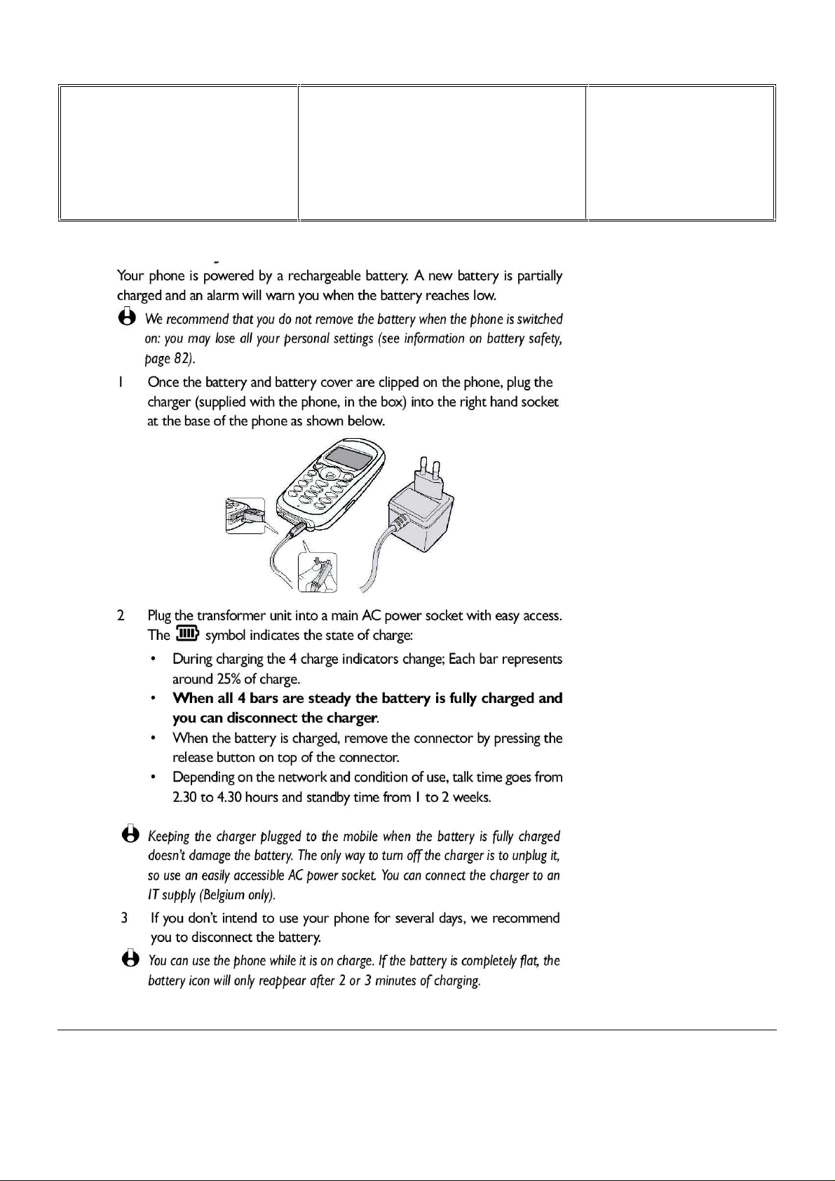
Removing the Battery......................................................................................................................................................10
7.5 Inse rt ing The MICRO- C ard...................................................................................................................................10
7.6 Inse rt ing The Battery.............................................................................................................................................11
Attach The Battery Cover .................................................................................................................................................11
7.8 Charging The Battery............................................................................................................................................12
7.9 Customise your Phone........................................................................................................................................... 13
7.10 W@P Introduction................................................................................................................................................15
7.11 GPRS Introduction................................................................................................................................................17
7.12 E-Mail Presentation........................................................................................................ .......................................24
8.0 TE ST PROCE DURE S ............................................................................................................................................25
8.1 Initial Functional Check for Fisio 620-CT3328 and Fisio 625-CT3329 ...................................................................25
8.2 RF Test.................................................................................................................................................................29
8.3 Battery Charging (IGN : Ignition) / Current Consumption......................................................................................34
8.4 W@P Test Procedure............................................................................................................................................36
8.5 E-Mail Test Procedure..........................................................................................................................................44
9.0 ASSE MBLY / DISMANTLEMENT PROCEDURES............................................................................................49
9.1 Dismantlement......................................................................................................................................................49
9.2 Assembly..............................................................................................................................................................54
9.3 Explosed View ......................................................................................................................................................58
10.0 SOLUTIONS IN CASE OF PROBLEMS DURING THE TESTS ........................................................................60
11.0 RECOMENDED PART LIST CT3328 FISIO620..................................................................................................62
12.0 RECOMENDED PART LIST CT3329 FISIO625..................................................................................................62
ANNEX 1............................................................................................................................................................................63
PHILIPS ELECTRONICS N.V. 1999 VY-V-640-620-3
All rights reserved. Reproduction in whole
or in part is prohibited without the written
consent of the copyright owner.

Départ. Technic al s uppo rt- CM640 PROCEDURE COMPANY RESTRICTED
PHILIPS Con sumer
Communications
Service Repair Support
VY-V-640-620-3
Page : 4 of 63
Centre du Mans
Language : EN
Date : 11/02/03
1.0 PURPOSE
This document establishes the functional t est and inspect ion procedures for the first level service repair of the
FISIO 620 Transceiver (CT3328) and FISIO 625 Transceiver ( CT3329) .
2.0 SCOPE
The test plan is appli c able to all levels of service repair of t he FISIO 620 transceiver (CT3328) and FISIO 625
Transceiv er (CT3329).
3.0 REFERENCE
None.
4.0 GLOSSARY/ACRONYM LIST
Window or Bezzel Protective pl astic ov er the LCD display
SW Sof tware
PN Hardware Configur ation of the Mobile
CN Matrix for Types of SW used on the different hardware
HW Hardware
ASC Authorized Servic e Center
NSC National Service Center
Test SIM Card Used for functionality of PHILIPS Mobile Phones
Test SIM Card « SP » SIM Card used to simulate t he user int erface and enable radio tests
5.0 TEST EQUIPMENT AND TOOLS
Equipment / Tools
- Production Test SIM Card - Part No. : 4311 255 00781
- Test SIM Card « SP » - Part No. : 4311 255 00782
- Digital Multimeter - Recommended Model : Fl uk e
Specification with current readi ng in mA.
- Digital Radiocommunication Tester.
- Coupling system with shielded chamber.
Or
- Cradle with RF Cabl e - Part No.: 9911 240 34508
PHILIPS ELECTRONICS N.V. 1999 VY-V-640-620-3
All rights reserved. Reproduction in whole
or in part is prohibited without the written
consent of the copyright owner.

Départ. Technic al s uppo rt- CM640 PROCEDURE COMPANY RESTRICTED
PHILIPS Con sumer
Service Repair Support
Communications
Centre du Mans
6.0 TEST AND INSPECTION PLAN
The test plan is derived from the Product Test Reference of FISIO 620 and FI SIO 625.
6.1 User Interface Test
Use the Test SIM Card « SP »/ Production t o test t he transceiver s as f ollows :
• On/Off button
• LCD Backlight
• Keyboard Test
• Buzzer Test
• Vibrator Test
• Audio Test
• Antenna
• LCD
• IMEI
• Tester Status/ E epr om Status
Test ( to measure the radiated power level. Not necessary when using an antenna coupler)
VY-V-640-620-3
Page : 5 of 63
Language : EN
Date : 11/02/03
With a fast Charger connected with the PRODUCT’s bottom connector, check the full scrolling f rom one mode to
the next when charging IG N (Ignition) – Battery.
6.2 RF Test
The radio test must be performed with a Digital Radio Test Set. The mobile has to be set on the antenna coupler
inside the shielded chamber.
PHILIPS ELECTRONICS N.V. 1999 VY-V-640-620-3
All rights reserved. Reproduction in whole
or in part is prohibited without the written
consent of the copyright owner.

Départ. Technic al s uppo rt- CM640 PROCEDURE COMPANY RESTRICTED
PHILIPS Con sumer
Communications
Service Repair Support
VY-V-640-620-3
Page : 6 of 63
Centre du Mans
Language : EN
Date : 11/02/03
Or It can be tested using the Cr adle (in this case a measurement of the power radiated by the antenna has to be
performed)
Use the Test SIM Card « SP »to test the following RF items
• GSM 900 / DCS 1800 band
• GPRS capability
In case the RF tester i s not suitable for GPRS tests, GSM900/DCS1800 test may be consider ed as suf ficient
provided that the sensiv ity tests are strengthened by reducing the RF level down to -104dBm.
RRM
RLC / MAC
This reasoning i s based on the fact that all
the protocol steps (GP RS att ac h, GPRS
detach, …) are achieved on the GSM/DCS
bands and validated by Philips Approval
department.
The new parameter to chec k , int r oduc ed by
GPRS, would be BLER (Blocks Error Rate).
As shown on the drawing, it inv olves more
modules than BER
Signals paths
BLER comp a r ed to BER
L1
[Sequencer]
HARDWARE LAYER
Function book for DSP control]
[
DSP
BER
BLER CS1 to CS4
PHILIPS ELECTRONICS N.V. 1999 VY-V-640-620-3
All rights reserved. Reproduction in whole
or in part is prohibited without the written
consent of the copyright owner.
Départ. Technic al s uppo rt- CM640 PROCEDURE COMPANY RESTRICTED
PHILIPS Con sumer
Communications
Centre du Mans
7.0 BEFORE STARTING
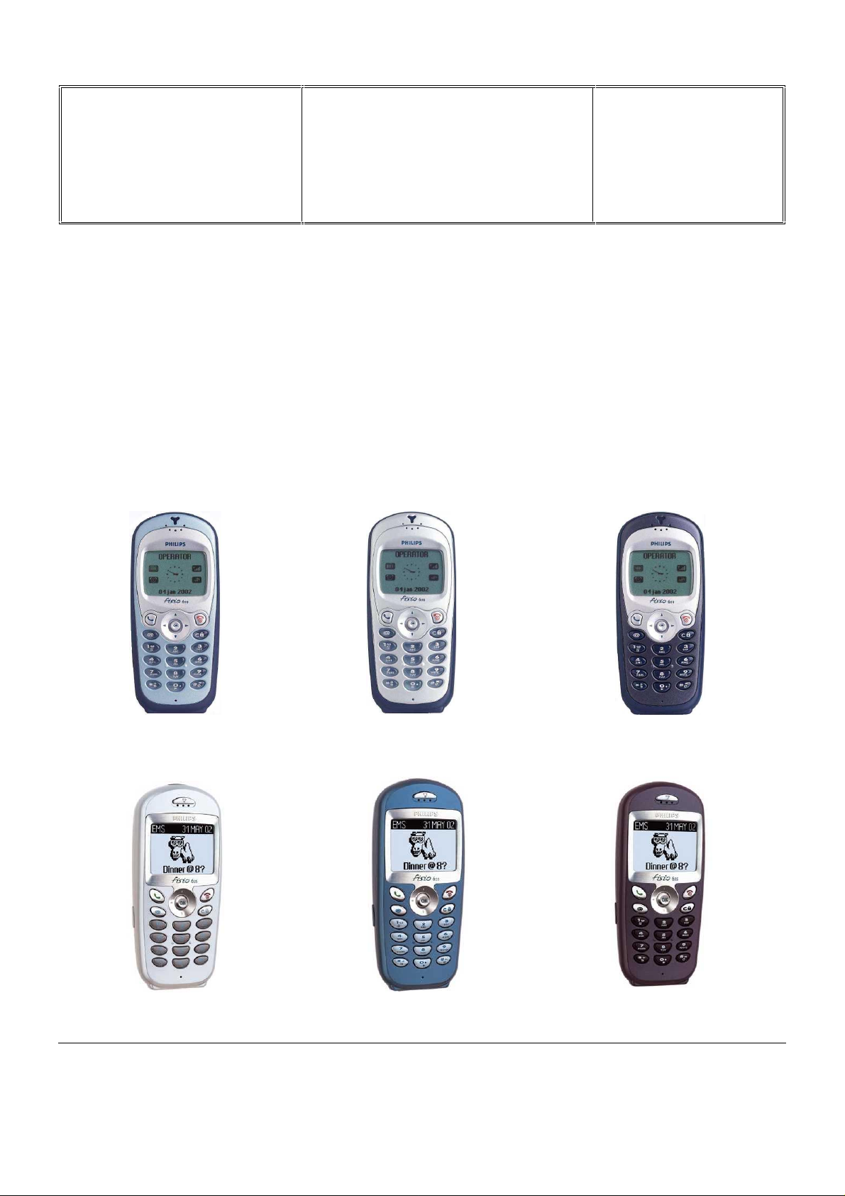
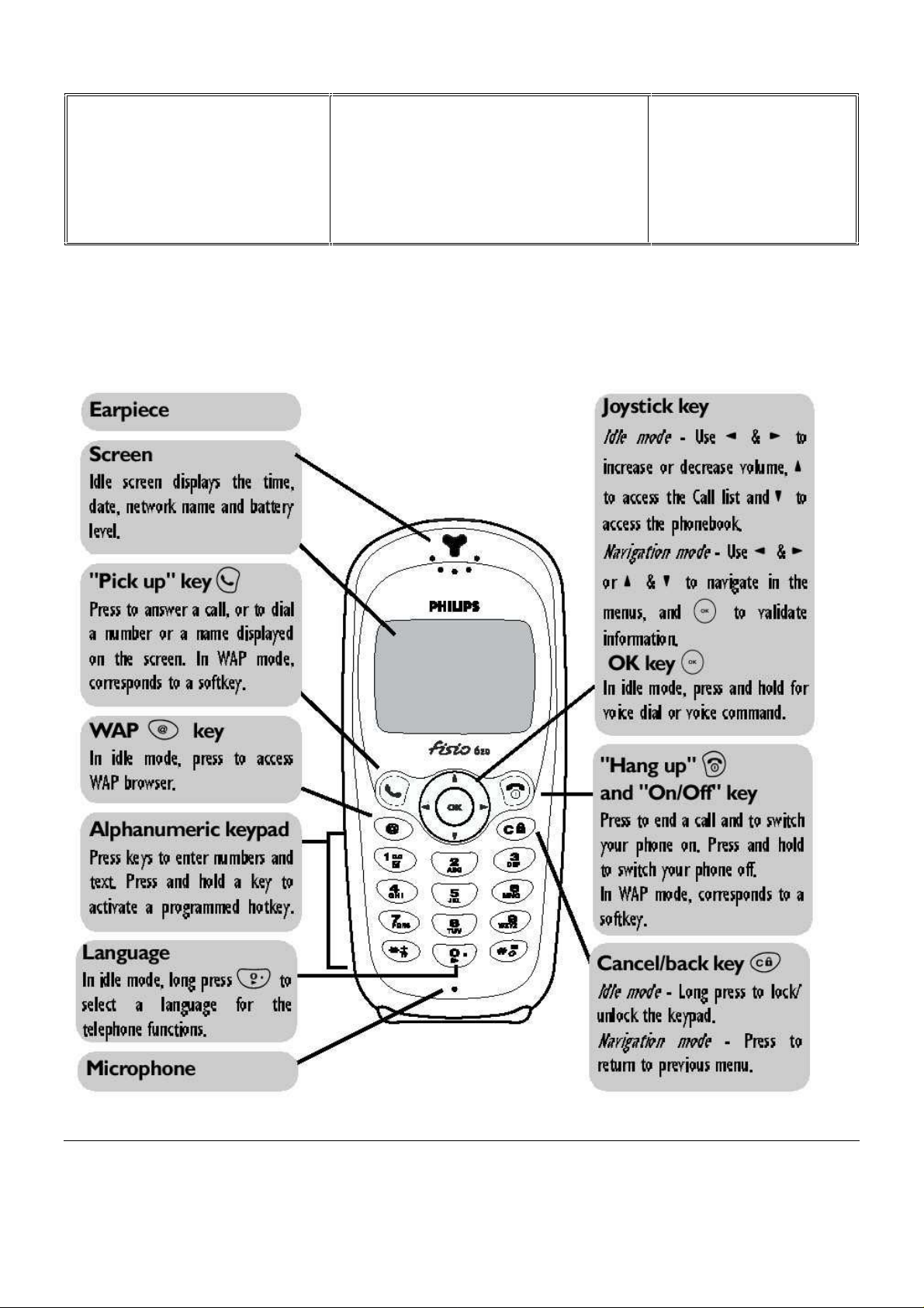
7.1 Description Of The Transceiver
Service Repair Support
VY-V-640-620-3
Page : 7 of 63
Language : EN
Date : 11/02/03
PHILIPS ELECTRONICS N.V. 1999 VY-V-640-620-3
All rights reserved. Reproduction in whole
or in part is prohibited without the written
consent of the copyright owner.
Départ. Technic al s uppo rt- CM640 PROCEDURE COMPANY RESTRICTED
PHILIPS Con sumer
Communications
Centre du Mans
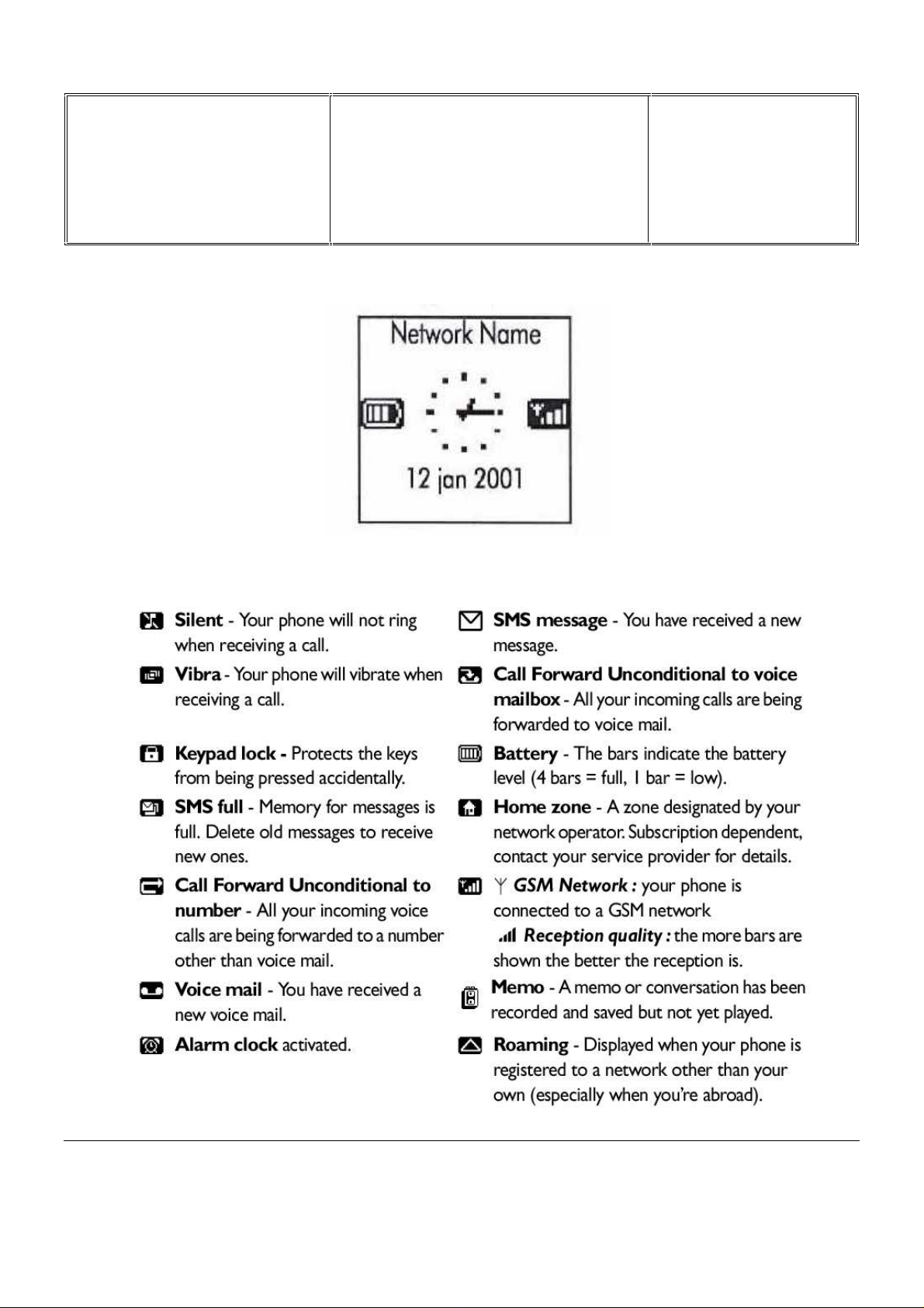
7.2 Description Of The Display
Service Repair Support
VY-V-640-620-3
Page : 8 of 63
Language : EN
Date : 11/02/03
PHILIPS ELECTRONICS N.V. 1999 VY-V-640-620-3
All rights reserved. Reproduction in whole
or in part is prohibited without the written
consent of the copyright owner.

Départ. Technic al s uppo rt- CM640 PROCEDURE COMPANY RESTRICTED
PHILIPS Con sumer
Communications
Service Repair Support
VY-V-640-620-3
Page : 9 of 63
Centre du Mans
Language : EN
Date : 11/02/03
7.3 Using The Carousel
The carousel i s a circ ular loop of icons displayed on the screen. These i c ons provide access to the different m enus
and sub menus used to operate your phone.
PHILIPS ELECTRONICS N.V. 1999 VY-V-640-620-3
All rights reserved. Reproduction in whole
or in part is prohibited without the written
consent of the copyright owner.
Départ. Technic al s uppo rt- CM640 PROCEDURE COMPANY RESTRICTED
PHILIPS Con sumer
Communications
Centre du Mans
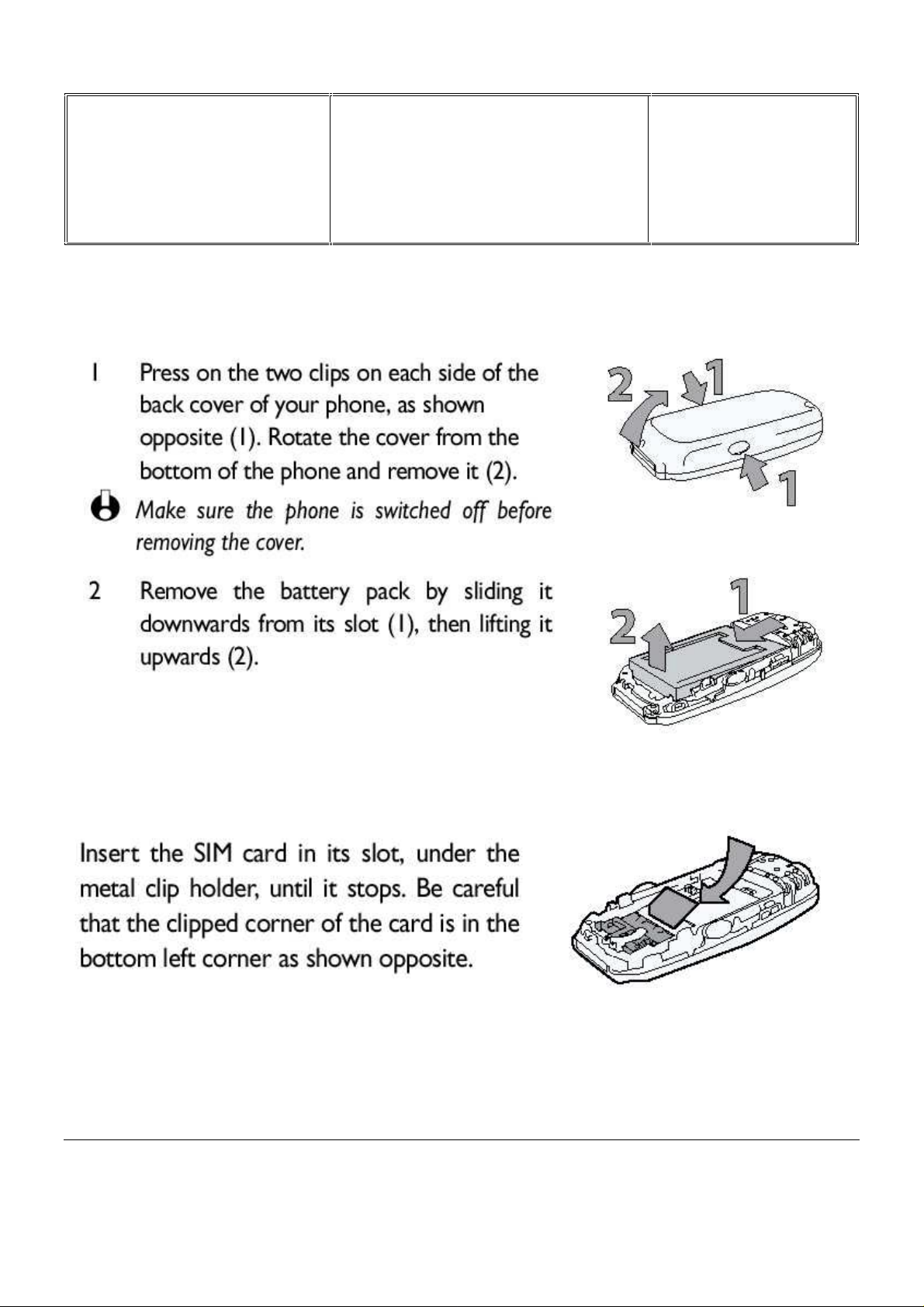
7.4 Removing the Battery
Service Repair Support
VY-V-640-620-3
Page : 10 of 63
Language : EN
Date : 11/02/03
7.5 Inserting The MICRO-Card
PHILIPS ELECTRONICS N.V. 1999 VY-V-640-620-3
All rights reserved. Reproduction in whole
or in part is prohibited without the written
consent of the copyright owner.

Départ. Technic al s uppo rt- CM640 PROCEDURE COMPANY RESTRICTED
PHILIPS Con sumer
Communications
Centre du Mans
7.6 Inserting The Battery
Service Repair Support
VY-V-640-620-3
Page : 11 of 63
Language : EN
Date : 11/02/03
7.7 Attach The Battery Cover
PHILIPS ELECTRONICS N.V. 1999 VY-V-640-620-3
All rights reserved. Reproduction in whole
or in part is prohibited without the written
consent of the copyright owner.
Départ. Technic al s uppo rt- CM640 PROCEDURE COMPANY RESTRICTED
PHILIPS Con sumer
Communications
Centre du Mans
7.8 Charging The Battery
Service Repair Support
VY-V-640-620-3
Page : 12 of 63
Language : EN
Date : 11/02/03
PHILIPS ELECTRONICS N.V. 1999 VY-V-640-620-3
All rights reserved. Reproduction in whole
or in part is prohibited without the written
consent of the copyright owner.

Départ. Technic al s uppo rt- CM640 PROCEDURE COMPANY RESTRICTED
PHILIPS Con sumer
Communications
Centre du Mans
7.9 Customise your Phone
Service Repair Support
VY-V-640-620-3
Page : 13 of 63
Language : EN
Date : 11/02/03
PHILIPS ELECTRONICS N.V. 1999 VY-V-640-620-3
All rights reserved. Reproduction in whole
or in part is prohibited without the written
consent of the copyright owner.

Départ. Technic al s uppo rt- CM640 PROCEDURE COMPANY RESTRICTED
PHILIPS Con sumer
Communications
Centre du Mans
Service Repair Support
VY-V-640-620-3
Page : 14 of 63
Language : EN
Date : 11/02/03
PHILIPS ELECTRONICS N.V. 1999 VY-V-640-620-3
All rights reserved. Reproduction in whole
or in part is prohibited without the written
consent of the copyright owner.
Départ. Technic al s uppo rt- CM640 PROCEDURE COMPANY RESTRICTED
PHILIPS Con sumer
Communications
Service Repair Support
VY-V-640-620-3
Page : 15 of 63
Centre du Mans
Language : EN
Date : 11/02/03
7.10 W@P Introduction
The purpose of W@p (Wirel ess Application Protocol) is to enable easy and fast delivery of relevant informati on and
services to m obile users. However, mobile Internet does not mean navigating on the Internet wit h a wireless devic e
but rather to access to some services in a mobile context.
The W@P architect ure was designed to enable standard Internet servers to provide servi ces to wireless dev ices.
The W@P wireless protocol is based on Internet standards such as HTTP and TLS but has been optimized
according to the c onstr aints of the wireless terminals: low memory capacity, small screen size
and of the network: limited bandwidth.
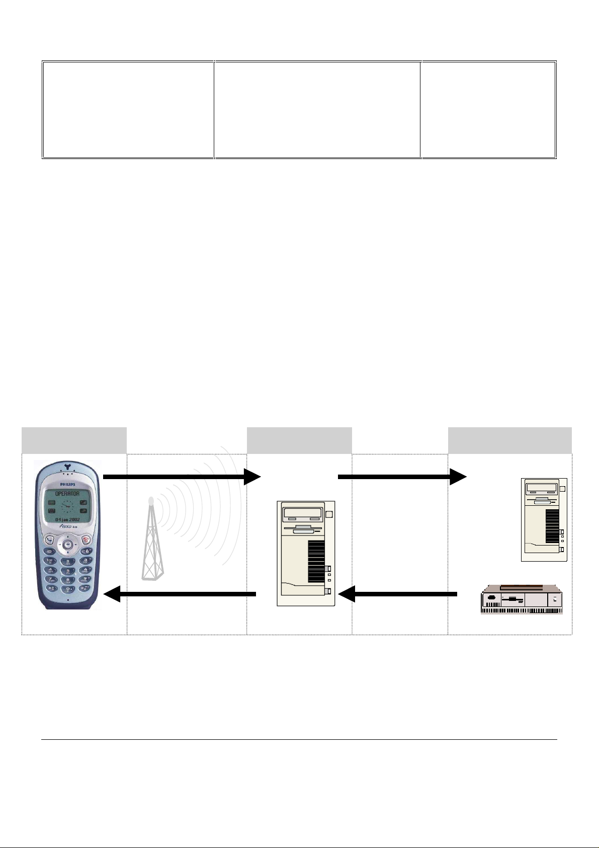
The W@P architect ur e is made up of 4 tec hnological parts which are necessary for accessing W@P services on a
mobile phone. These are:
W@P navigator or br owser
Mobile operator network
W@P gateway / W@P server
Web server
Customer Gateway Server
1.0 Encoded
Request
4.0 Encoded
Answer
Encoder/
Decoder
2.0 Request
Content
Generation
3.0 Answer
PHILIPS ELECTRONICS N.V. 1999 VY-V-640-620-3
All rights reserved. Reproduction in whole
or in part is prohibited without the written
consent of the copyright owner.

Départ. Technic al s uppo rt- CM640 PROCEDURE COMPANY RESTRICTED
PHILIPS Con sumer
Communications
Service Repair Support
VY-V-640-620-3
Page : 16 of 63
Centre du Mans
Language : EN
Date : 11/02/03
* Subscription
The customer has to contact his Network Operator to inquire about his subscription and the options he can
subscribe to. Generally the customer just have to request his W@P access to his provider and he will not be
charged for that.
* W@P parameters
Parameters hav e to be set in t he m obile phone in order to access W@P services . Howev er, there ar e two
cases depending on the commercial offer:
* Transceiv er sold v ia an oper ator package
- Parameters cannot be ac c essed f r om the W@P settings menu of the mobile phone:
The transceiver is W@P locked. The W@P connections will always be made from the
operator W@P homepage and search engines will be available. The customer will have to
ask for a password fr om hi s/her oper ator to unlock the W@P settings.
(with subscription included):
- Parameters can be acc essed f r om the W@P settings menu of the mobile
phone:
The customer changes the W @P par am eters according to his/her own convenience.
* Retail transceiver
- Phones are configur ed by the manufacturer with no W@P parameter. The end user has
to ensure that the W@P f unctionalities and a data/fax options have been subscribed.
The end user has also to set the W@P param eters by asking for them from
his/her operator or by usi ng par am eters of another company (available on
Internet, newspaper etc.)
Detailed parameters
Phone Number
(or User Name) : if requested by your IS P
Login
The password : if requested by your IS P
IP address for the Gateway : for communicati ons between Int er net Service Provider and Gateway
& Port Number (for a secure or non secure connection)
Home page address
Please note that it is important to respect small and capital letters according to your oper ator instructions.
It is also possible that your provider does not require the Login and/or Password.
(or dial-up number) : to establish a connection with the Internet Service Provider
(or URL address): for communications between Gateway and Web server
(without subscription included):
PHILIPS ELECTRONICS N.V. 1999 VY-V-640-620-3
All rights reserved. Reproduction in whole
or in part is prohibited without the written
consent of the copyright owner.

Départ. Technic al s uppo rt- CM640 PROCEDURE COMPANY RESTRICTED
PHILIPS Con sumer
Communications
Service Repair Support
VY-V-640-620-3
Page : 17 of 63
Centre du Mans
Language : EN
Date : 11/02/03
7.11 GPRS Introduction
7.11.1 Presentation
The GPRS does not constitute to him alone a separate mobile network, but a supplementary layer added to a
existing GSM network.
It can be thus settled without any supplementary license. This means that all the operators who have a GSM
license can develop their network towards it.
Furthermor e, the GPRS uses wavebands att ri buted to t he GSM. that means a band i n the 900 MHz , t he other one
in the 1800 MHz and finally the third for the USA, in the 1900 MHz
The GPRS, also called GSM 2+, rests on the transmission of data packets. This pri ncipl e, already hel d for exam ple
for the protocol X.25, allows to allocate to the other communic ations, t he time- outs of a first c ommunicati on (wait of
an answer to an Internet r equest for example).
Conceived to reuse at most the existing GSM infrastructures, the expansion of the GPRS requires the
implementation of a network infrastructure based on the data packets routi ng and the int r oduc tion of bridges to lean
on existing GSM networks.
This technol ogy, capabl e of supplying transf er rates rising up to 115 kb/s (against 9,6 kb/ s for the GSM), offers
interesting features:
• Several channels can be allocated to a single user;
• Several users can share a single c hannel;
• The transmission rate is independent from rising and downward links.
7.11.2 Services / Possibilities / Limit ations
Domains of application
While the WAP stops in the consultation of the Internet pages, the GPRS allows to widen the servi ce offer . Besides
the access to Internet (or Intranet), from the traditional mobiles phones, it allows a better access to e-mails
containing joined files.
A rate higher than the wired public network
Today, the transmi ssion rate of a standard GSM network in "connect ed" mode does not overtake 9, 6 kbit/s, ev en
14,4 kbit/s by establi shment of specifi c software. It is five tim es less fast compared t o the standard wired network,
which authorises 56 kbit/s with a V90 modem.
PHILIPS ELECTRONICS N.V. 1999 VY-V-640-620-3
All rights reserved. Reproduction in whole
or in part is prohibited without the written
consent of the copyright owner.

Départ. Technic al s uppo rt- CM640 PROCEDURE COMPANY RESTRICTED
PHILIPS Con sumer
Communications
Service Repair Support
VY-V-640-620-3
Page : 18 of 63
Centre du Mans
Language : EN
Date : 11/02/03
With the GPRS, a transmi ssion rate included between 40 and 115 kbit/ s is availabl e. Everything depends on the
number of virtual canals or " time slots " used, and on coding scheme (CS1 to CS4). GPRS acts on the
compression of t he data as a multiplier of transmission rat e. In 3+1 multislots mode (three slots for the network
towards mobil e, and a slot for the mobil e towards net work), it’s allows a transmission r ate of 40 kbit/s with a CS2
coding scheme.
With (8+1)multi sl ots using the CS4 coding scheme, one achieves i n pr actic e 115 k bit/s (in theory 175 kbit/s).
If, as it seems to be the current will of the operators, GPRS re-uses the ex isting GSM infrastructure, notably by
keeping the network of current base stations ( BTS), upgrading the BTS software.
Average time t o send an E-m ail with a 10 pages attached document :
Standard Rate Time elapsed
Current GSM 9,6 kbit/s 7 min.
Standard Modems (V90) 57,6 kbit/s 70 sec.
RNIS 128 kbit/s 31 sec.
GPRS 144 bit/s * 28 sec.
EDGE 384 kbit/ s * 10 sec.
UMTS 2 Mbit/s 2 sec.
* : in optimal conditions
Three types of air terminals
Three types of air terminals were defined to meet the needs of the GPRS: the basic model (cl ass B) is foreseen f or
the voice and the data i n not simultaneous m ode. The prof essional or industri al model (cl ass C) i s dat a exclusi v ely
(the air termi nal is used as a m odem ). Finally the up-market (class A ) is compati ble voice/data simultaneously. This
class A terminal is problematic. The power of calculation required at the moment has a strong incidence on its
production cost and makes it dissuasive.
In the GPRS standard, thr ee new types of mobile terminal have been defined:
Class A terminal, which support s simultaneous cir c uit-switched and packed-switched t r aff ic;
Class B terminal, which supports either circuit-switched or packed-switched traffic (simultaneous network
attachment) but does not support both kinds of traffic simultaneously;
Class C terminal, whic h is attached either as a packed-switched or c ir c uit-switched terminal.
The terminal types are further differentiated by their ability to handle multislot operations. The terminal can use
from 1 up to 8 time slots on the uplink and on t he downlink channel . 18 servic es cl asses are defined i n f uncti on on
the number for support time slots.
PHILIPS ELECTRONICS N.V. 1999 VY-V-640-620-3
All rights reserved. Reproduction in whole
or in part is prohibited without the written
consent of the copyright owner.

Départ. Technic al s uppo rt- CM640 PROCEDURE COMPANY RESTRICTED
PHILIPS Con sumer
Communications
Centre du Mans
Service Repair Support
Servic
e Class
1 112 1
2 213 1
3 223 1
4 314 1
5 224 1
6 324 1
7 334 1
8 415 1
9 325 1
10 425 1
11 435 1
12 445 1
13 336 2
14 448 2
15 5510 2
16 6612 2
17 7714 2
18 8816 2
Max Number of Slots
MaxRxMaxTxTotal
available
Multislot
type
Fig. 1 Service Classes - Multislot operations
VY-V-640-620-3
Page : 19 of 63
Language : EN
Date : 11/02/03
Four different channel-coding schemes have been defined for GPRS to make optimum use of varying radio
conditions. Usage of higher coding schemes all ows to send mor e data in the same number of time slots.
Channel Coding
CS-1 CS-2 CS-3 CS-4
Scheme
Data rate per
9.05 13.4 15.6 21.4
timeslot (kbps)
Fig. 2 GPRS Coding Schemes
Philips Fisio620 features GP RS Class B. With GPRS Class B, if you receiv e incoming call s whil e in the middle of a
data session, you receive a notification; and v ic e versa.
Philips Fisio620 is enabled to support GPRS up to Class10 (4Rx, 2Tx) [depending on networks developments].
GPRS Class10 enables to rec eiv e information at l east 4 times faster t han a standard G SM connection and to send
them 2 times faster. T hat is why GPRS Class10 is partic ularly suit able for surfing on the W AP pages, ex changing
emails or using y our phone as a modem for Int er net surfing, Intranet br owsing or fi le transfer.
Philips Fisi o620 is SMG31bis - Coding schemes 1,2,3 and 4.
PHILIPS ELECTRONICS N.V. 1999 VY-V-640-620-3
All rights reserved. Reproduction in whole
or in part is prohibited without the written
consent of the copyright owner.
 Loading...