

Page 1
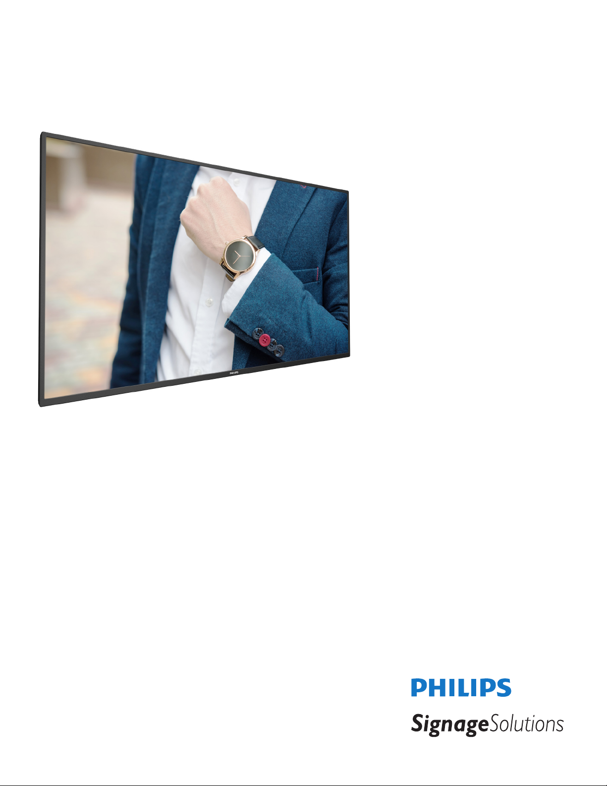
32BDL4051D
43BDL4051D
49BDL4051D
55BDL4051D
V1.00
www.philips.com/welcome
User Manual (English)
Page 2
Safety Instructions
Safety precautions and maintenance
WARNING: Use of controls, adjustments or procedures other than those specied in this documentation may result in exposure to
shock, electrical hazards and/or mechanical hazards.
Read and follow these instructions when connecting and using your display:
Operation:
• Keep the display out of direct sunlight and away from stoves or any other heat sources.
• Remove any object that could fall into ventilation holes or prevent proper cooling of the display’s electronics.
• Do not block the ventilation holes on the cabinet.
• When positioning the display, make sure the power plug and outlet are easily accessible.
• When turning off the display by detaching the power cord, wait 6 seconds before re-attaching the power cord for normal operation.
• Ensure the use of an approved power cord provided by Philips at all times. If your power cord is missing, please contact your local service center.
• Do not subject the display to severe vibration or high impact conditions during operation.
• Do not knock or drop the display during operation or transportation.
• The eye bolt is for usage in short-time maintenance and installation. We suggest not to use the eye bolt for more than 1 hour. Prolong usage is
prohibited. Please keep a clear safety area under the display while using the eye bolt.
Maintenance:
• To protect your display from possible damage, do not put excessive pressure on the LCD panel. When moving your display, grasp the frame to lift; do
not lift the display by placing your hand or ngers on the LCD panel.
• Unplug the display if you are not going to use it for an extensive period of time.
• Unplug the display if you need to clean it with a slightly damp cloth. The screen may be wiped with a dry cloth when the power is off. However, never
use organic solvent, such as, alcohol, or ammonia-based liquids to clean your display.
• To avoid the risk of shock or permanent damage to the set, do not expose the display to dust, rain, water or an excessively moist environment.
• If your display becomes wet, wipe it with dry cloth as soon as possible.
• If a foreign substance or water gets in your display, turn the power off immediately and disconnect the power cord. Then remove the foreign substance
or water, and send the unit to the maintenance center.
• Do not store or use the display in locations exposed to heat, direct sunlight or extreme cold.
• In order to maintain the best performance of your display and ensure a longer lifetime, we strongly recommend using the display in a location that falls
within the following temperature and humidity ranges.
- Temperature: 0-40°C 32-104°F
- Humidity: 20-80% RH
• LCD panel temperature need to be 25 degrees Celsius at all time for better luminance performance.
IMPORTANT: Always activate a moving screen saver program when you leave your display unattended. Always activate a periodic screen refresh
application if the unit will display unchanging static content. Uninterrupted display of still or static images over an extended period may cause “burn in”,
also known as “after-imaging” or “ghost imaging”, on your screen. This is a well-known phenomenon in LCD panel technology. In most cases, the “burned
in” or “after-imaging” or “ghost imaging” will disappear gradually over a period of time after the power has been switched off.
WARNING: Severe “burn-in” or “after-image” or “ghost image” symptoms will not disappear and cannot be repaired. This is also not covered under the
terms of your warranty.
Service:
• The casing cover should be opened only by qualied service personnel.
• If there is any need for repair or integration, please contact your local service center.
• Do not leave your display under direct sunlight.
If your display does not operate normally, having followed the instructions set out in this document, please contact a technician or your
local service center.
ii
Page 3
Stability Hazard.
The device may fall, causing serious personal injury or death. To prevent injury, this device must be securely attached to the oor/wall in accordance with
the installation instructions.
Read and follow these instructions when connecting and using your display:
• Unplug the display if you are not going to use it for an extensive period of time.
• Unplug the display if you need to clean it with a slightly damp cloth. The screen many be wiped with a dry cloth when the power is
off. However, never use alcohol, solvents or ammonia-based liquids.
• Consult a service technician if the display does not operate normally when you have followed the instructions in this manual.
• The casing cover should be opened only by qualied service personnel.
• Keep the display out of direct sunlight and away from stoves or any other heat sources.
• Remove any object that could fall into the vents or prevent proper cooling of the display’s electronics.
• Do not block the ventilation holes on the cabinet.
• Keep the display dry. To avoid electric shock, do not expose it to rain or excessive moisture.
• When turning off the display by detaching the power cable or DC power cord, wait for 6 seconds before re-attaching the power
cable or DC power cord for normal operation..
• To avoid the risk of shock or permanent damage to the set do not expose the display to rain or excessive moisture.
• When positioning the display, make sure the power plug and outlet are easily accessible.
• IMPORTANT: Always activate a screen saver program during your application. If a still image in high contrast remains on the
screen for an extended period of time, it may leave an ‘after-image’ or ‘ghost image’ on the front of the screen. This is a well-known
phenomenon that is caused by the shortcomings inherent in LCD technology. In most cases the afterimage will disappear gradually
over a period of time after the power has been switched off. Be aware that the after-image symptom cannot be repaired and is not
covered under warranty.
CAUTION
DOUBLE POLE/NEUTRAL FUSING
EU Declaration of Conformity
This device complies with the requirements set out in the Council Directive on the Approximation of the Laws of the Member States relating to
Electromagnetic Compatibility (2014/30/EU), Low-voltage Directive (2014/35/EU), RoHS directive (2011/65/EU), and Radio Equipment Directive (2014/53/
EU).
This product has been tested and found to comply with the harmonized standards for Information Technology Equipment, these harmonized standards
published under Directives of Ofcial Journal of the European Union.
ESD Warnings
When user close to the monitor may cause the equipment discharge and reboot to the display of main menu.
Warning:
This equipment is compliant with Class A of EN55032/CISPR 32. In a residential environment this equipment may cause radio interference.
Federal Communications Commission (FCC) Notice (U.S. Only)
NOTE: This equipment has been tested and found to comply with the limits for a Class A digital device, pursuant to part 15 of the
FCC Rules. These limits are designed to provide reasonable protection against harmful interference when the equipment is operated
in a commercial environment. This equipment generates, uses, and can radiate radio frequency energy and, if not installed and used in
accordance with the instruction manual, may cause harmful interference to radio communications. Operation of this equipment in a
residential area is likely to cause harmful interference in which case the user will be required to correct the interference at his own
expense.
Changes or modications not expressly approved by the party responsible for compliance could void the user’s authority to operate the
equipment.
Use only an RF shielded cable that was supplied with the display when connecting this display to a computer device.
To prevent damage which may result in re or shock hazard, do not expose this appliance to rain or excessive moisture.
This device complies with Part 15 of the FCC Rules. Operation is subject to the following two conditions: (1) This device may not cause harmful
interference, and (2) this device must accept any interference received, including interference that may cause undesired operation.
iii
Page 4
Envision Peripherals Inc.
490 N McCarthy Blvd, Suite #120
Milpitas, CA 95035
USA
Europe – EU Declaration of Conformity
This device complies with the essential requirements of the Radio Equipment Directive (2014/53/EU). The following test methods have been applied in
order to prove presumption of conformity with the essential requirements of the Radio Equipment Directive (2014/53/EU):
- EN60950-1/EN62311/EN300328/EN301893/EN301489
Europe Statement
IMPORTANT NOTE:
The device is restricted to indoor use only when operating in the 5150 to 5350MHz frequency range.
AT BE BG HR CY CZ DK
EE FI FR DE EL HU IE
IT LV LT LU MT NL PL
PT RO SK SI ES SE UK
Radiation Exposure Statement:
This equipment complies with CE radiation exposure limits set forth for an uncontrolled environment. This equipment should be installed and
operated with minimum distance 20cm between the radiator & body.
The frequency, mode and the maximum transmitted power in EU are listed below:
2412-2472MHz(802.11g 6Mbps): 19.98dBm
2402-2480MHz (EDR 3Mbps): 9.65dBm
2402-2480MHz (LE 1Mbps): 9.80dBm
5180-5240/5260-5320/5500-5700MHz (802.11 ac VHT40 MCS0/NSS1): 22.95dBm
Taiwan:
低功率電波輻射性電機管理辦法
第十二條 經型式認證合格之低功率射頻電機,非經許可,公司、商號或使用者均不得擅自變更頻率、加
大功率或變更原設計之特性及功能。
第十四條 低功率射頻電機之使用不得影響飛航安全及干擾合法通信;經發現有干擾現象時,應立即停用,
並改善至無干擾時方得繼續使用。
前項合法通信,指依電信法規定作業之無線電通信。
低功率射頻電機須忍受合法通信或工業、科學及醫療用電波輻射性電機設備之干擾。
Caution:
Any changes or modications not expressly approved by the party responsible for compliance could void the user’s authority to operate this equipment.
This transmitter must not be co-located or operating in conjunction with any other antenna or transmitter.
Operations in the 5GHz products are restricted to indoor usage only.
Radiation Exposure Statement:
This equipment complies with FCC radiation exposure limits set forth for an uncontrolled environment. This equipment should be installed and operated
with minimum distance 20cm between the radiator & your body.
iv
Page 5
Canada:
Industry Canada statement:
This device complies with RSS-247 of the Industry Canada Rules. Operation is subject to the following two conditions: (1) This device may not cause
harmful interference, and (2) this device must accept any interference received, including interference that may cause undesired operation.
Ce dispositif est conforme à la norme CNR-247 d’Industrie Canada applicable aux appareils radio exempts de licence. Son fonctionnement est sujet aux
deux conditions suivantes: (1) le dispositif ne doit pas produire de brouillage préjudiciable, et (2) ce dispositif doit accepter tout brouillage reçu, y compris
un brouillage susceptible de provoquer un fonctionnement indésirable.
Radiation Exposure Statement:
This equipment complies with ISED radiation exposure limits set forth for an uncontrolled environment. This equipment should be installed and operated
with minimum distance 20cm between the radiator & your body.
Déclaration d’exposition aux radiations:Cet équipement est conforme aux limites d’exposition aux rayonnements ISED établies pour un environnement
non contrôlé. Cet équipement doit être installé et utilisé avec un minimum de 20 cm de distance entre la source de rayonnement et votre corps.
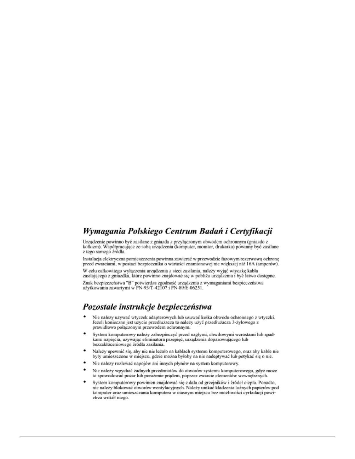
Polish Center for Testing and Certication Notice
The equipment should draw power from a socket with an attached protection circuit (a three-prong socket). All equipment that works together (computer,
display, printer, and so on) should have the same power supply source.
The phasing conductor of the room’s electrical installation should have a reserve short-circuit protection device in the form of a fuse with a nominal value
no larger than 16 amperes (A).
To completely switch off the equipment, the power supply cable must be removed from the power supply socket, which should be located near the
equipment and easily accessible.
A protection mark “B” conrms that the equipment is in compliance with the protection usage requirements of standards PN-93/T-42107 and PN-89/
E-06251.
v
Page 6
Electric, Magnetic and Electromagnetic Fields (“EMF”)
1. We manufacture and sell many products targeted at consumers, which, like any electronic apparatus, in general have the ability to emit and receive
electromagnetic signals.
2. One of our leading Business Principles is to take all necessary health and safety measures for our products, to comply with all applicable legal
requirements and to stay well within the EMF standards applicable at the time of producing the products.
3. We are committed to develop, produce and market products that cause no adverse health effects.
4. We conrm that if its products are handled properly for their intended use, they are safe to use according to scientic evidence available today.
5. We play an active role in the development of international EMF and safety standards, enabling us to anticipate further developments in standardization
for early integration in its products.
Information for U.K. only
WARNING - THIS APPLIANCE MUST BE EARTHED.
(B)
(A)
Important:
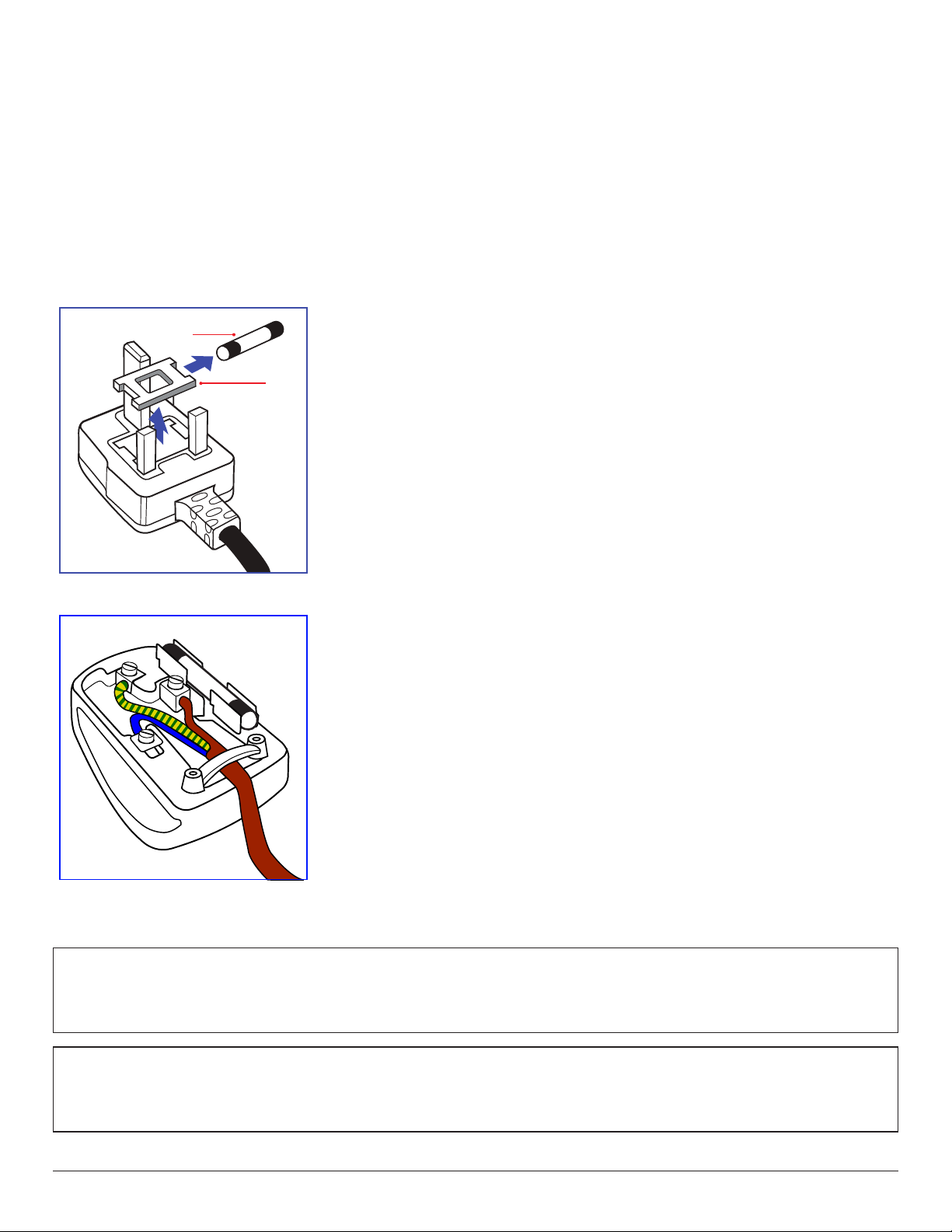
This apparatus is supplied with an approved moulded 13A plug. To change a fuse in this type of plug
proceed as follows:+
1. Remove fuse cover and fuse.
2. Fit new fuse which should be a BS 1362 5A,A.S.T.A. or BSI approved type.
3. Ret the fuse cover.
If the tted plug is not suitable for your socket outlets, it should be cut off and an appropriate 3-pin
plug tted in its place.
If the mains plug contains a fuse, this should have a value of 5A. If a plug without a fuse is used, the fuse
at the distribution board should not be greater than 5A.
NOTE: The severed plug must be destroyed to avoid a possible shock hazard should it be inserted
into a 13A socket elsewhere.
How to connect a plug
The wires in the mains lead are coloured in accordance with the following code:
BLUE - “NEUTRAL” (“N”)
BROWN - “LIVE” (“L”)
GREEN & YELLOW - “EARTH” (“E”)
1. The GREEN & YELLOW wire must be connected to the terminal in the plug which is marked with
the letter “E” or by the Earth symbol or coloured GREEN or GREEN & YELLOW.
2. The BLUE wire must be connected to the terminal which is marked with the letter “N” or coloured
BLACK.
3. The BROWN wire must be connected to the terminal which marked with the letter “L” or
coloured RED.
Before replacing the plug cover, make certain that the cord grip is clamped over the sheath of the lead
- not simply over the three wires.
North Europe (Nordic Countries) Information
Placering/Ventilation
VARNING:
FÖRSÄKRA DIG OM ATT HUVUDBRYTARE OCH UTTAG ÄR LÄTÅTKOMLIGA, NÄR DU STÄLLER DIN UTRUSTNING PÅPLATS.
Placering/Ventilation
ADVARSEL:
SØRG VED PLACERINGEN FOR, AT NETLEDNINGENS STIK OG STIKKONTAKT ER NEMT TILGÆNGELIGE.
vi
Page 7
Paikka/Ilmankierto
VAROITUS:
SIJOITA LAITE SITEN, ETTÄ VERKKOJOHTO VOIDAAN TARVITTAESSA HELPOSTI IRROTTAA PISTORASIASTA.
Plassering/Ventilasjon
ADVARSEL:
NÅR DETTE UTSTYRET PLASSERES, MÅ DU PASSE PÅ AT KONTAKTENE FOR STØMTILFØRSEL ER LETTE Å NÅ.
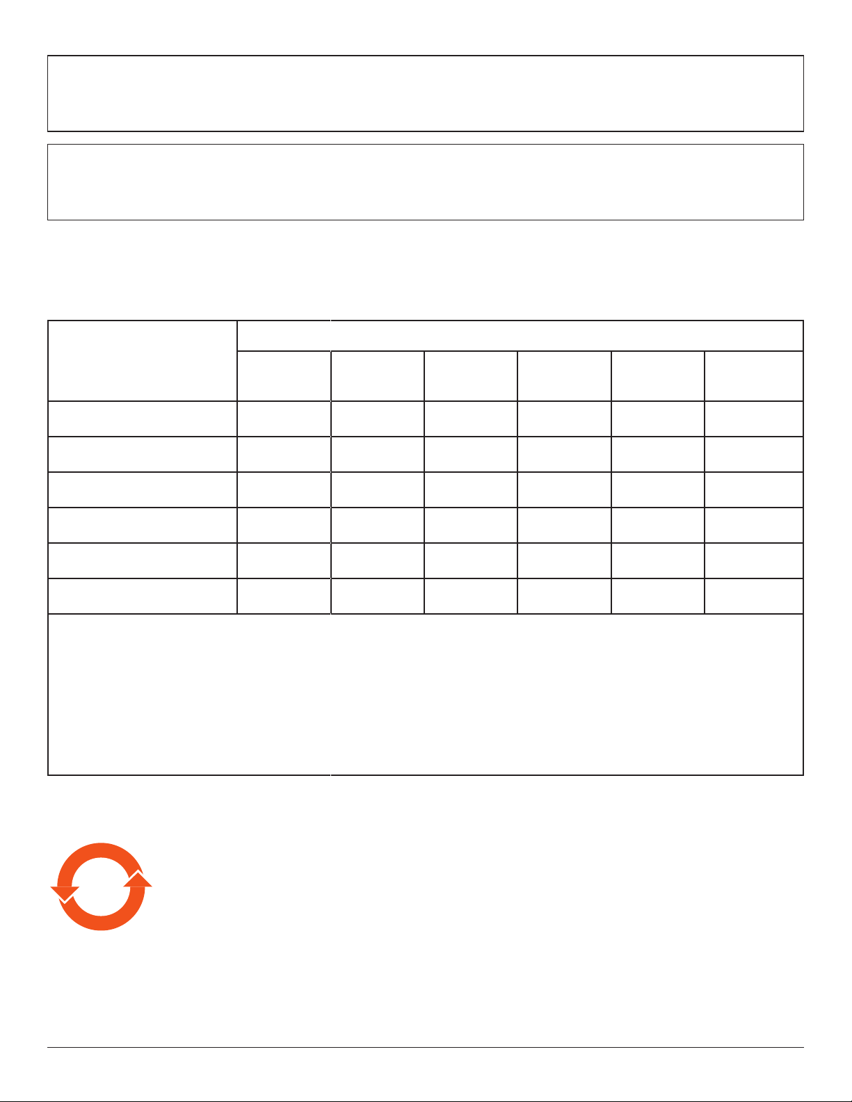
China RoHS
根据中国大陆《电器电子产品有害物质限制使用管理办法》,以下部分列出了本产品中可能包含的有害
物质的名称和含量。
有害物质
部件名称
铅
(Pb)
汞
(Hg)
镉
(Cd)
六价铬
(Cr (VI))
多溴联苯
(PBB)
多溴二苯醚
(PBDE)
外壳 ○ ○ ○ ○ ○ ○
液晶显示屏 × ○ ○ ○ ○ ○
电路板组件* × ○ ○ ○ ○ ○
电源适配器 × ○ ○ ○ ○ ○
电源线/连接线 × ○ ○ ○ ○ ○
遥控器 X ○ ○ ○ ○ ○
本表格依据SJ/T 11364 的规定编制。
*: 电路板组件包括印刷电路板及其构成的零部件,如电阻、电容、集成电路、连接器等。
O: 表示该有害物质在该部件所有均质材料中的含量均在 GB/T 26572规定的限量要求以下。
X: 表示该有害物质至少在该部件的某一均质材料中的含量超出GB/T 26572规定的限量要求。
上表中打“×”的部件,应功能需要,部分有害物质含量超出GB/T 26572规定的限量要求,但符合欧盟RoHS
法规要求(属于豁免部分)。
备注:上表仅做为范例,实际标示时应依照各产品的实际部件及所含有害物质进行标示。
10
環保使用期限
此標識指期限(十年),電子電氣產品中含有的有害物質在正常使用的條件下不會發生外泄或突變,電子
電氣產品用戶使用該電子電氣產品不會對環境造成嚴重污染或對其人身、財產造成嚴重損害的期限。
vii
Page 8
《废弃电器电子产品回收处理管理条例》提示性说明
为了更好地关爱及保护地球,当用户不再需要此产品或产品寿命终止时,请遵守国家废弃电器电子产品
回收处理相关法律法规,将其交给当地具有国家认可的回收处理资质的厂商进行回收处理,不当利用或
者处置可能会对环境和人类健康造成影响。
娤⌈
㨢᳸$䵥ᵥ⍿Ʋ◦䏝㯹䉭❁ᳫ濕媣ᵥ⍿⊭侻廞ノ㒞䵽䏳ⴰㄮƲ◦店䢋⾃濕⊭侻斾堿䏦ヵ
⪷ⴰㄮ悅⊔⩜⊭圊䕂㉨㑻Ʋ
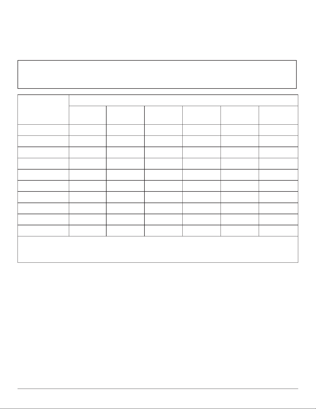
限用物質及其化學符號
單元
鉛
(Pb)
汞
(Hg)
鎘
(Cd)
六價鉻
(Cr+6)
多溴聯苯
(PBB)
多溴二苯醚
(PBDE)
塑料外框 ○ ○ ○ ○ ○ ○
後殼 ○ ○ ○ ○ ○ ○
液晶面板 - ○ ○ ○ ○ ○
電路板組件 - ○ ○ ○ ○ ○
底座 ○ ○ ○ ○ ○ ○
電源線 - ○ ○ ○ ○ ○
其他線材 - ○ ○ ○ ○ ○
遙控器 - ○ ○ ○ ○ ○
喇叭(選配) - ○ ○ ○ ○ ○
風扇(選配) - ○ ○ ○ ○ ○
備考1.〝○〞係指該項限用物質之百分比含量未超出百分比含量基準值。
備考2.〝-〞係指該項限用物質為排除項目。
警語 : 使用過度恐傷害視力。
注意事項 :
(1) 使用30分鐘請休息10分鐘。
(2) 未滿2歲幼兒不看螢幕,2歲以上每天看螢幕不要超過1小時。
警告使用者 :
此為甲類資訊技術設備 , 於居住環境中使用時 , 可能會造成射頻擾動 , 在此種情況下 , 使用者會被
要求採取某些適當的對策。
Turkey RoHS:
Türkiye Cumhuriyeti: EEE Yönetmeliğine Uygundur
Ukraine RoHS:
Обладнання відповідає вимогам Технічного регламенту щодо обмеження використання деяких небезпечних речовин в електричному та
електронному обладнанні, затвердженого постановою Кабінету Міністрів України від 3 грудня 2008 № 1057
viii
Page 9
End-of-Life Disposal
Your new Public Information Display contains materials that can be recycled and reused. Specialized companies can recycle your product to increase the
amount of reusable materials and to minimize the amount to be disposed of.
Please nd out about the local regulations on how to dispose of your old display from your local Philips dealer.
(For customers in Canada and U.S.A.)
This product may contain lead and/or mercury. Dispose of in accordance to local-state and federal regulations. For additional information on recycling
contact www.eia.org (Consumer Education Initiative)
Waste Electrical and Electronic Equipment-WEEE
Attention users in European Union private households
This marking on the product or on its packaging illustrates that, under European Directive 2012/19/EU governing used electrical and
electronic appliances, this product may not be disposed of with normal household waste. You are responsible for disposal of this
equipment through a designated waste electrical and electronic equipment collection. To determine the locations for dropping off such
waste electrical and electronic, contact your local government ofce, the waste disposal organization that serves your household or the
store at which you purchased the product.
Attention users in United States:
Please dispose of according to all Local, State and Federal Laws. For the disposal or recycling information, contact: www.mygreenelectronics.com or
www.eiae.org.
End of Life Directives-Recycling
Your new Public Information Display contains several materials that can be recycled for new users.
Please dispose of according to all Local, State, and Federal laws.
43BDL4051D/55BDL4051D:
ENERGY STAR is a program run by the U.S. Environmental Protection Agency (EPA) and U.S. Department of Energy (DOE) that
promotes energy efciency.
This product qualies for ENERGY STAR in the “factory default” settings and this is the setting in which power savings will be achieved.
Changing the factory default picture settings or enabling other features will increase power consumption that could exceed the limits
necessary to qualify for ENERGY STAR rating.
For more information on the ENERGY STAR program, refer to energystar.gov.
Restriction on Hazardous Substances statement (India)
This product complies with the “E-Waste (Management) Rules, 2016” CHAPTER V, rule 16, sub-rule (1) . Whereas New Electrical and Electronic
Equipment and their components or consumables or parts or spares do not contain Lead, Mercury, Cadmium, Hexavalent Chromium, polybrominated
biphenyls and polybrominated diphenyl ethers beyond a maximum concentration value of 0.1% by weight in homogenous materials for lead, mercury,
hexavalent chromium, polybrominated biphenyls and polybrominated diphenyl ethers and of 0.01% by weight in homogenous materials for cadmium.
except of exemptions set in Schedule 2 of the Rule.
E-Waste Declaration for India
This symbol on the product or on its packaging indicates that this product must not be disposed of with your other household waste.
Instead it is your responsibility to dispose of your waste equipment by handing it over to a designated collection point for the recycling
of waste electrical and electronic equipment . The separate collection and recycling of your waste equipment at the time of disposal
will help to conserve natural resources and ensure that it is recycled in a manner that protects human health and the environment.
For more information about E -waste please visit http://www.india.philips.com/about/sustainability/recycling/index.page and to know
where you can drop off your waste equipment for recycling in India please contact on below given contact details.
Helpline number: 1800-425-6396 (Monday to Saturday, 9 a.m. to 5:30 pm)
E-mail: [email protected]
ix
Page 10
Batteries
Após o uso, as pilhas
deverão ser entregues ao
estabelecimento comercial
ou
e/ou baterias
rede de assistência técnica
autorizada.
For EU: The crossed-out wheeled bin implies that used batteries should not be put to the general household waste! There is a separate
collection system for used batteries, to allow proper treatment and recycling in accordance with legislation.
Please contact your local authority for details on the collection and recycling schemes.
For Switzerland: The used battery is to be returned to the selling point.
For other non-EU countries: Please contact your local authority for correct method of disposal of the used battery.
According to EU directive 2006/66/EC, the battery can’t be disposed improperly. The battery shall be separated
to collect by local service.
Information for EAC
Month and year of manufacturing please refer information in Rating label.
Name and location of manufacturer
Importer and information
ООО “Профтехника”
Адрес: 3-й Проезд Марьиной рощи, 40/1 офис 1. Москва, 127018, Россия
Наименование организации: ООО “Профтехника”
Адрес: 3-й Проезд Марьиной рощи, 40/1 офис 1. Москва, 127018, Россия
Контактное лицо: Наталья Астафьева,
+7 495 640 20 20
[email protected]
Information for FAC:
“Подтверждение соответствия Мининформсвязи России: Декларация соответствия № Д-PD-4342 от 01.09.2016 года, действительна до
01.09.2024 года, зарегистрирована в Федеральном агенстве связи 14.09.2016 года”
x
Page 11

Table Of Contents
1. Unpacking and Installation .......................................................1
1.1. Transportation and Unpacking.............................................1
1.2. Package Contents ........................................................................2
1.3. Installation Notes .........................................................................2
1.4. Installing or removing the table stand (optional) .....3
1.5. Mounting on a Wall ....................................................................5
1.6. Mounting in Portrait Orientation ....................................... 7
1.7. Operating Instructions of Edge Alignment Kit ............8
2. Parts and Functions ...................................................................9
2.1. Control Panel .................................................................................9
2.2. Input/Output Terminals ..........................................................10
2.3. Remote Control ........................................................................ 15
2.4. SD card Cover ...........................................................................19
3. Connecting External Equipment.......................................... 20
3.1. Connecting External Equipment (DVD/VCR/
VCD) ...............................................................................................20
3.2. Connecting a PC ....................................................................... 20
3.3. Connecting Audio Equipment ...........................................21
3.4. Connecting Multiple Displays in a Daisy-chain
Conguration .............................................................................. 21
3.5. IR connection .............................................................................. 22
3.6. IR Pass-through Connection ............................................... 23
5.12. Supplementary ........................................................................... 44
6. OSD Menu ............................................................................... 47
6.1. Navigating the OSD Menu ................................................47
6.2. OSD Menu Overview ........................................................... 47
7. Supported Media Formats .................................................... 56
8. Input Mode ............................................................................... 58
9. Pixel Defect Policy .................................................................. 60
9.1. Pixels and Sub-Pixels ...............................................................60
9.2. Types of Pixel Defects + Dot Denition .................... 60
9.3. Bright Dot Defects ...................................................................60
9.4. Dark Dot Defects.....................................................................61
9.5. Proximity of Pixel Defects ...................................................61
9.6. Pixel Defect Tolerances ......................................................... 61
9.7. MURA ............................................................................................. 61
10. Cleaning and Troubleshooting .............................................. 62
10.1. Cleaning ..........................................................................................62
10.2. Troubleshooting ......................................................................... 63
11. Technical Specications ......................................................... 65
4. Operation ................................................................................. 24
4.1. Watch the Connected Video Source ............................ 24
4.2. Change Picture Format ......................................................... 24
4.3. Overview.......................................................................................24
4.4. Media Player.................................................................................26
4.5. Browser .......................................................................................... 29
4.6. PDF Player ....................................................................................32
4.7. CMND & Play ............................................................................. 34
4.8. Custom App ................................................................................ 34
5. Setting ........................................................................................ 35
5.1. Wi-Fi ............................................................................................... 35
5.2. Ethernet..........................................................................................35
5.3. More (available when 4G module is connected) ...35
5.4. Signage Display ........................................................................... 35
5.5. Display ............................................................................................. 43
5.6. Apps ................................................................................................. 43
5.7. Security ........................................................................................... 43
5.8. Input method .............................................................................. 43
5.9. Date & time ................................................................................. 44
5.10. Developer options ...................................................................44
5.11. About .............................................................................................. 44
xi
Page 12
1. Unpacking and Installation
1.1. Transportation and Unpacking
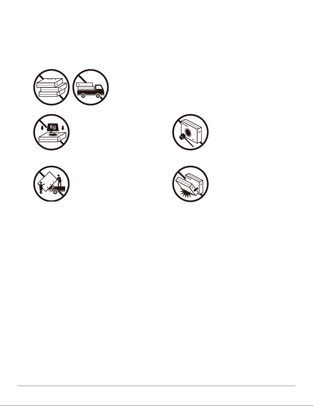
Notice for transportation
• Always keep the carton in a vertical position.
Do NOT place the carton in any other direction.
• Do NOT place any object on the carton. • Do NOT apply shock/vibration to the product.
• Move the carton by stacker. • Do NOT drop the product. Strong impacts may
damage the components inside.
1
Page 13
Before installing the display
• This product is packed in a carton, together with the standard accessories.
• Any other optional accessories will be packed separately.
• Move the display by at least two (2) adults.
• After opening the carton, ensure that the contents are complete and in good condition.
1.2. Package Contents
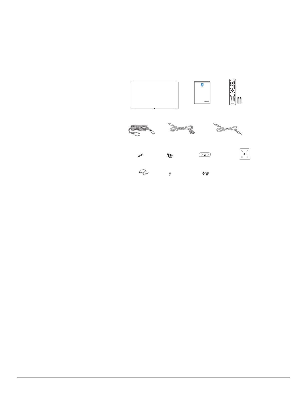
Please verify that you received the following items with your package content:
• LCD display
• Quick start guide
• Remote Control and AAA batteries
• Power cord
• RS232 cable
• RS232 daisy chain cable
• Logo
• Edge Alignment Kit-1: 2PCS
• Edge Alignment Kit-2: 1PCS
• Thumb Screw: 8PCS
• SD card cover and M3 screw x1
• M2 screw x2
* The supplied power cord varies depending on destination.
Power Cord
Logo
Quick start guide
RS232 Daisy Chain CableRS232
NORMAL
ID
FORMAT
SOURCE
INFOLIST
OPTIONSADJUST
VOL
ID SET ENTER
Remote Control
and AAA Batteries
Edge Alignment Kit-2 x 1Edge Alignment Kit-1 x 2Thumb Screw x 8
SD card cover M3 M2
* Items may differ in different locations
* Display design and accessories may differ from the images shown.
NOTES:
• For all other regions, apply a power cord that conforms to the AC voltage of the power socket and has been approved by and complies with the
safety regulations of the particular country (Type H05W-F, 2G or 3G, 0.75 or 1 mm2 should be used).
• Keep the packaging materials appropriately after unpacking the product.
1.3. Installation Notes
• Only use the power cable provided with this product. If an extension cord is required, please consult your service agent.
• The product should be installed on a at surface, or the product may tip over. Leave a space between the rear of the product and the wall for proper
ventilation. Do not install the product in a kitchen, bathroom or a place exposed to moisture, failure to do so may shorten the life of the internal
parts.
• Do not install the product where it is 3000m and higher in altitude. Failure to do so may result in malfunctions.
2
Page 14
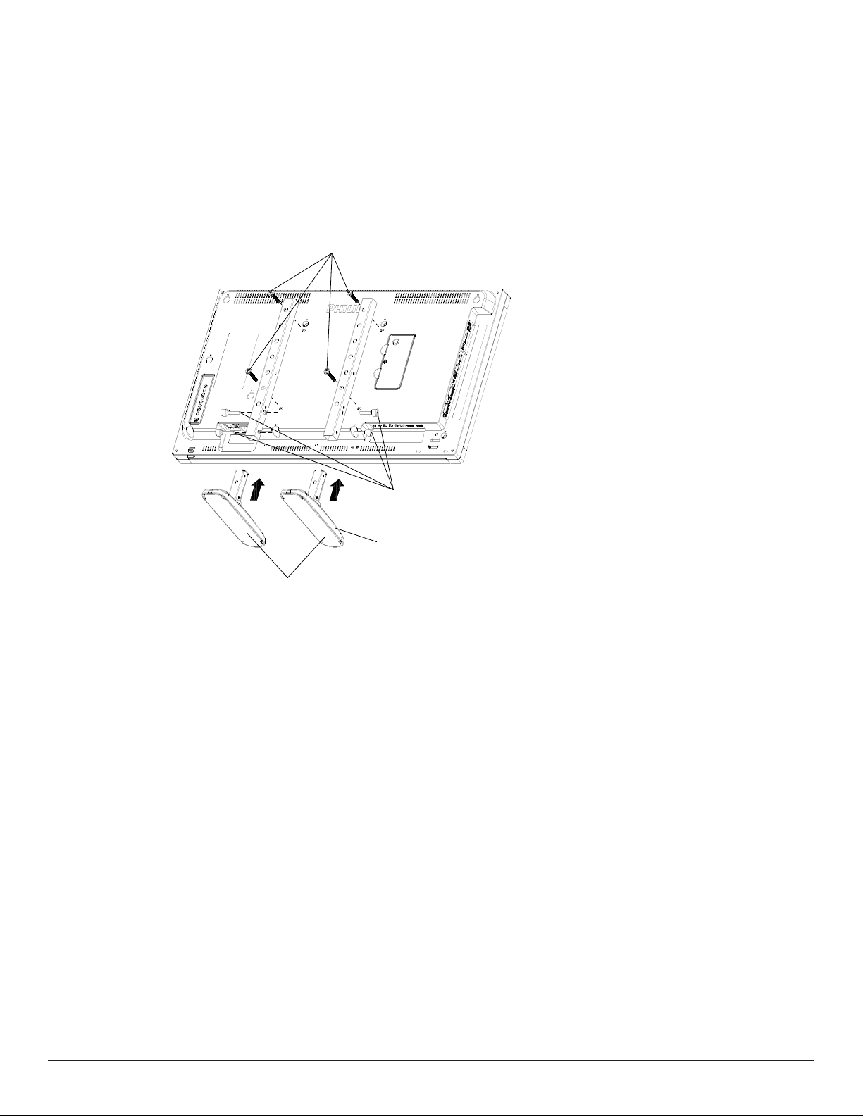
1.4. Installing or removing the table stand (optional)
Table stand
Step 1- Place on the table
Take off the protective sheet which was wrapped around the display when it was packaged. Lay the protective sheet on the table, beneath the screen
surface so as not to scratch the screen face.
Step 2- Fix the tube to the display (by using M6xL41 screws)
Please refer to the following drawing to identify the position of screws.
32BDL4051D: Fasten the longest screw(M6x41.0mm) into Hole#1 and Hole#7 of tube to secure it to the display.
Step 3- Set up the stand (using thumb screws)
M6xL41 screws
Thumb screws
Longer portions should face the front
To remove the table stands:
1. Power off the display.
2. Spread a protective sheet on a at surface.
3. Place the display face-down on the protective sheet.
4. Remove screws using a screwdriver and place them in a safe place for reuse.
3
Page 15
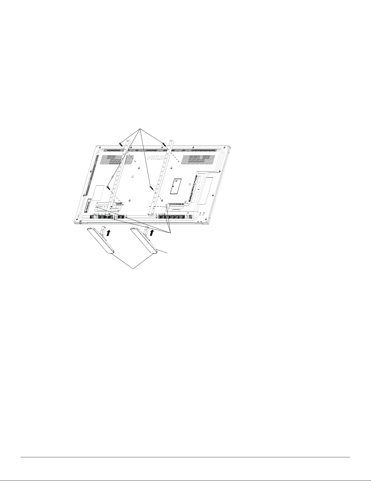
Installing or removing the table stand (optional)
Step 1- Place on the table
Take off the protective sheet which was wrapped around the display when it was packaged. Lay the protective sheet on the table, beneath the screen
surface so as not to scratch the screen face.
Step 2- Fix the tube to the display (by using M6xL41 screws)
Please refer to the following drawing to identify the position of screws.
55BDL4051D: Fasten the longest screw(M6x41.0mm) into Hole#3 and Hole#13 of tube to secure it to the display.
49BDL4051D: Fasten the longest screw(M6x41.0mm) into Hole#4 and Hole#14 of tube to secure it to the display.
43BDL4051D: Fasten the longest screw(M6x41.0mm) into Hole#5 and Hole#15 of tube to secure it to the display.
Step 3- Set up the stand (using thumb screws)
M6xL41 screws
Thumb screws
Longer portions should face the front
Table stand
To remove the table stands:
1. Power off the display.
2. Spread a protective sheet on a at surface.
3. Place the display face-down on the protective sheet.
4. Remove screws using a screwdriver and place them in a safe place for reuse.
4
Page 16
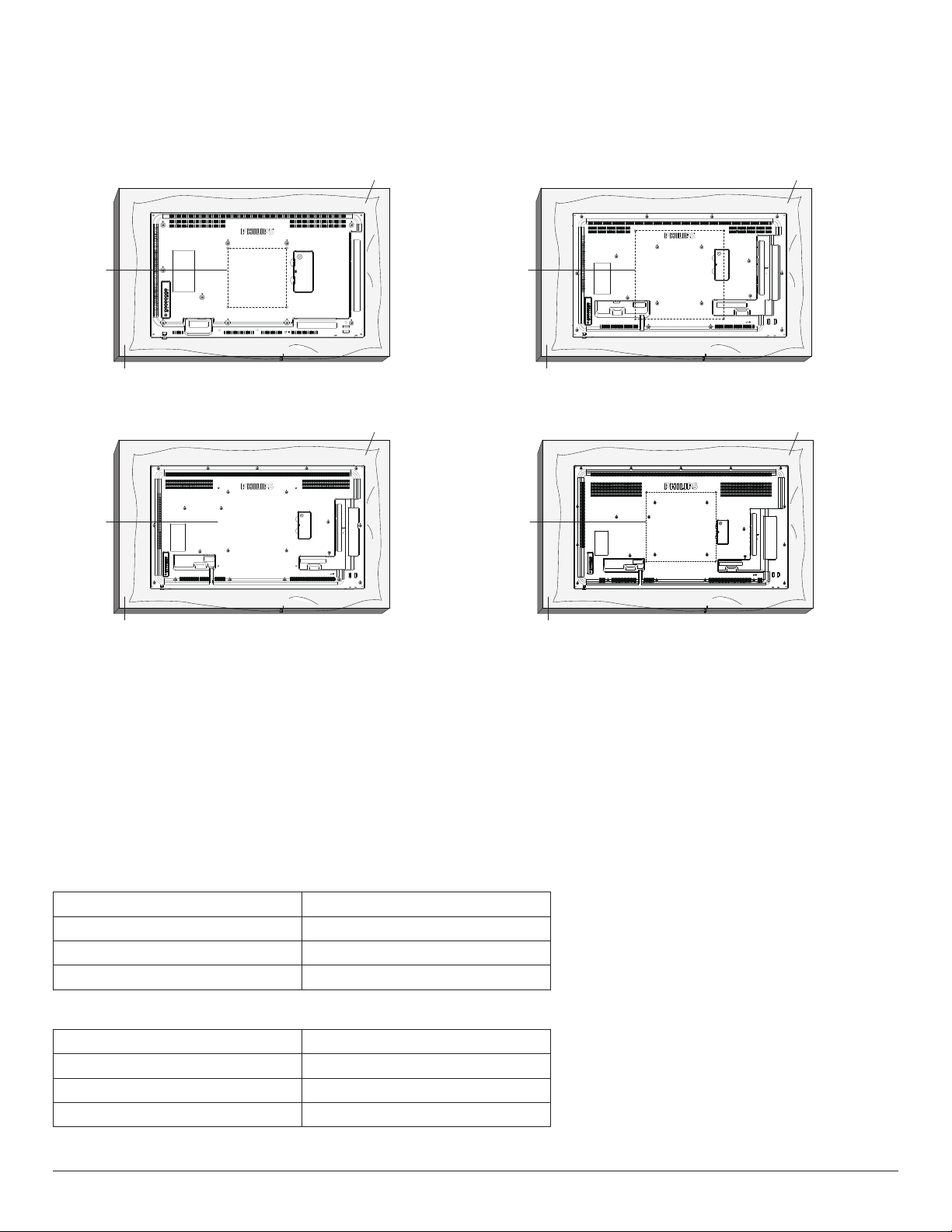
1.5. Mounting on a Wall
To mount this display on a wall, a standard wall-mounting kit (commercially available) is required. It is recommended that you use a mounting interface that
complied with TUV-GS and /or UL1678 standard in North America.
32BDL4051D 43BDL4051D
Protective Sheet
VESA Grid
Table
VESA Grid
Table
49BDL4051D 55BDL4051D
Protective Sheet
VESA Grid
VESA Grid
Protective Sheet
Protective Sheet
Table
Table
1. Prepare a at and horizontal surface that is larger than the display and spread a thick protective sheet on it to facilitate your operation without
scratching the screen.
2. Ensure you have all accessories for all types of mounting (wall mount, ceiling mount, table stand, etc).
3. Follow the instructions that came with the base mounting kit. Failure to follow the correct mounting procedures could result in damage to the
equipment, or injury to the user or installer. The product warranty does not cover the damage caused by improper installation.
4. For the wall-mounting kit, use the M6 mounting screws (with a length 10 mm longer than the thickness of the mounting bracket) and tighten them
securely.
5. The equipment and its associated mounting facilities still remain secure during the test. Use only the UL listed Wall Mount Bracket with a minimum
weight/load of the weight of the unit without base.
1.5.1. VESA Grid
32BDL4051D
43BDL4051D
49BDL4051D
55BDL4051D
200(H) x 200(V) mm
400(H) x 400(V) mm
400(H) x 400(V) mm
400(H) x 400(V) mm
1.5.2. Weight of the unit
32BDL4051D
43BDL4051D
49BDL4051D
55BDL4051D
6.15 kg
10.4 kg
14.8 kg
18.0 kg
5
Page 17
Caution:
To prevent the display from falling:
• For wall or ceiling mounting, we recommend that you install the display with metal brackets which are commercially available. For detailed instructions
about the installation, refer to the guide provided with the bracket.
• To prevent the display from falling in case of earthquake or other natural disaster, please consult the manufacturer of the bracket for the mounting
location.
• As this product is high and heavy, the installation of this product is recommended to be performed by four technicians.
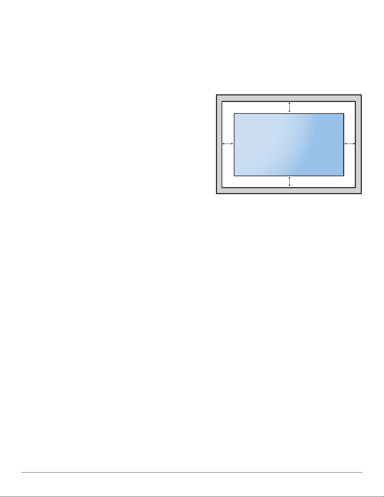
Ventilation Requirements for enclosure locating
Leave a space of 100 mm at the top, rear, right and left of the display for ventilation.
100 mm
100 mm 100 mm
100 mm
6
Page 18
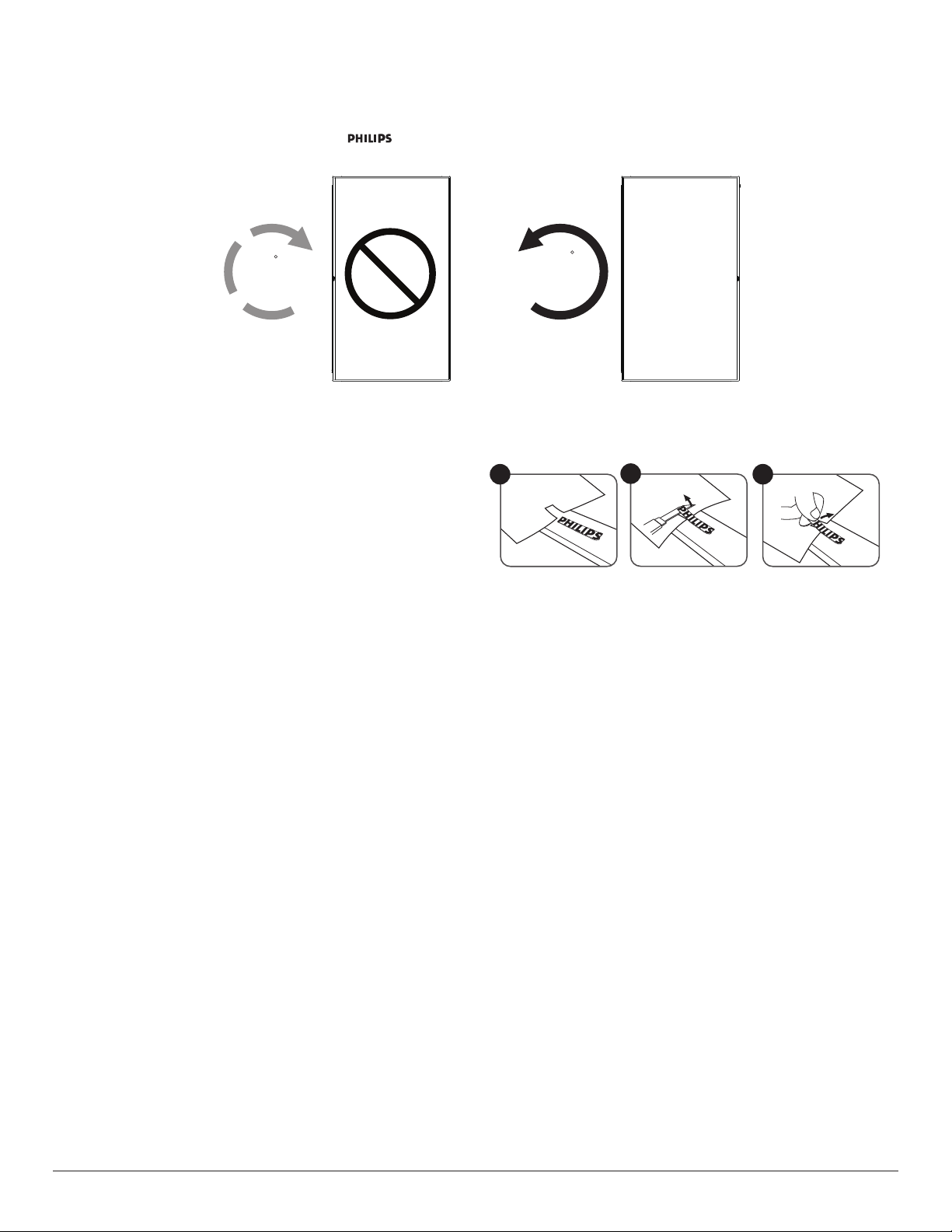
1.6. Mounting in Portrait Orientation
This display can be installed in portrait position.
1. If the table stand is attached, remove it rst.
2. Rotate the display counter-clockwise by 90°. The “ ” logo should be on the RIGHT side when facing the display.
90
90
1.6.1. How to remove the logo
1. Prepare a piece of paper with a cutting area of logo as a protector to
prevent the front bezel from scratching.
2. Use a knife and carefully remove the logo sticker with the paper placing
beneath.
3. Tear off the logo sticker.
NOTE: We recommend you contact a professional technician when installing the display on a wall. We are not responsible for any damage to the
product if the installation is not performed by a professional technician.
1
2
3
7
Page 19
1.7. Operating Instructions of Edge Alignment Kit
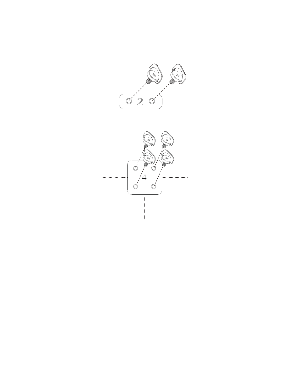
1.7.1. Installing Edge Alignment Kit
• Use “Edge Alignment Kit-1” for two adjacent displays.
• Install the “Edge Alignment Kit-1” with 2 PCS of M4 screw.
• Use “Edge Alignment Kit-2” for four adjacent displays.
NOTE: When installing the edge alignment kit, please consult a professional technician for proper installation. We accept no liability for installations not
performed by a professional technician.
8
Page 20
2. Parts and Functions
MUTE INPUT
MENU
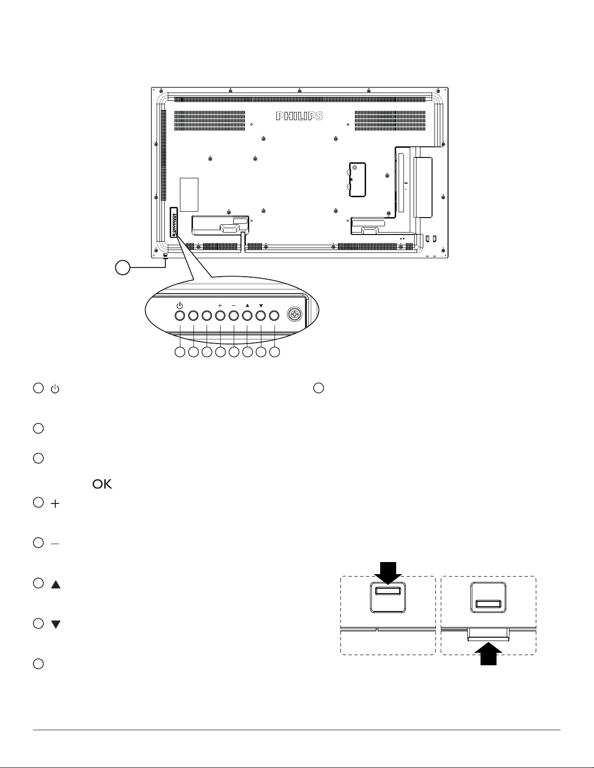
2.1. Control Panel
9
1 2 3 4 5 6 7 8
1
[ ] button
Use this button to turn the display on or put the display to standby
mode.
2
[MUTE] button
Switch the audio mute ON/OFF.
3
[INPUT] button
Choose the input source.
• Used as [ ] button in the On-Screen-Display menu.
4
[ ] button
Increase the adjustment while OSD menu is on, or increase the
audio output level while OSD menu is off.
5
[ ] button
Decrease the adjustment while OSD menu is on, or decrease the
audio output level while OSD menu is off.
6
[ ] button
Move the highlight bar up to adjust the selected item while OSD
menu is on.
7
[ ] button
Move the highlight bar down to adjust the selected item while OSD
menu is on.
9
Remote control sensor and power status indicator
• Receives command signals from the remote control.
• Indicates the operating status of the display without OPS:
- Lights green when the display is turned on
- Lights red when the display is in standby mode
- When {SCHEDULE} is enabled, the light blinks green and red
- If the light blinks red, it indicates that a failure has been
detected
- Lights off when the main power of the display is turned off
• Pull down the lens to have better remote control performance
and easy to observe the light information of power status.
• Push up the lens before mounting the display for video wall
application.
• Pull/Push the lens until hearing the click sound.
8
[MENU] button
Return to previous menu while OSD menu is on, or to activate the
OSD menu when OSD menu is off.
9
Page 21
2.2. Input/Output Terminals
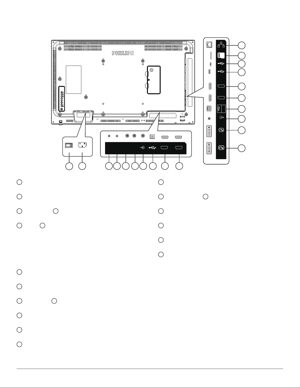
32BDL4051D
RS232
1
1
MAIN POWER SWITCH
RS232
IN
2
3 4 5 6 7 8 9 10
OUT
IR-IN IR-OUT
Switch the main power on/off.
2
AC IN
AC power input from the wall outlet.
3
RS232C IN / 4 RS232C OUT
RS232C network input / output for the loop-through function.
5
IR IN / 6 IR OUT
IR signal input / output for the loop-through function.
NOTES:
• This display’s remote control sensor will stop working if the jack
[IR IN] is connected.
• To remotely control your A/V device via this display, refer to
page 23 for IR Pass Through connection.
7
AUDIO IN
Audio input for VGA source (3.5mm stereo phone).
8
USB PORT B
Reserve for Touch model.
9
HDMI1 IN / 10 HDMI2 IN
HDMI video/audio input.
11
DVI IN
DVI-I video input.
12
DVI OUT
DVI or VGA video output.
13
AUDIO OUT
Audio output to external AV device.
AUDIO
LINE-IN
MICRO SD
MICRO USB
AUDIO-LINE
USB-B
HDMI 1 IN HDMI 2 IN
14
USB PORT
Connect your USB storage device.
15
DisplayPort IN / 16 DisplayPort OUT
DisplayPort video input / output.
17
USB PORT
Connect your USB storage device.
18
MICRO USB
Connect your USB storage device.
19
MICRO SD CARD
Connect your MICRO SD CARD.
20
RJ-45
LAN control function for the use of remote control signal from
control center for installing the optional OPS module.
RJ45
USB
DP OUT
DP IN
OUT
DVI OUT
DVI IN
20
19
18
17
16
15
USB
5V/2A
14
13
12
11
10
Page 22
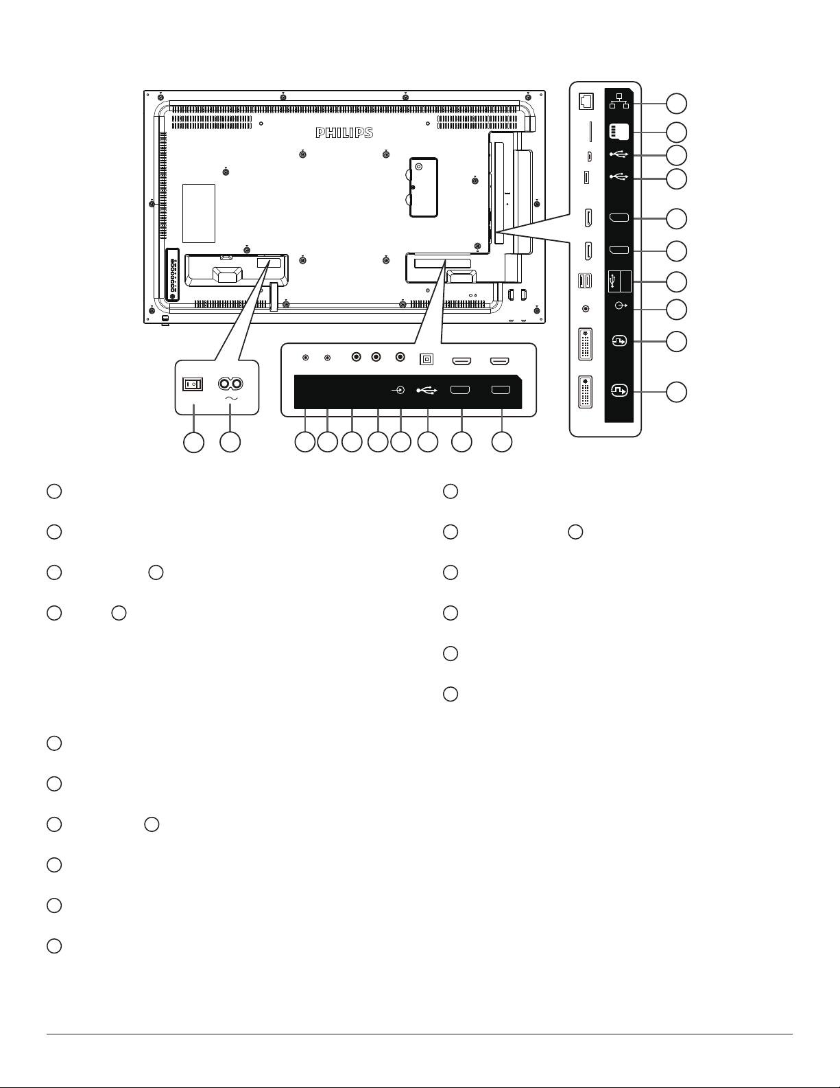
43BDL4051D
RS232
1
1
MAIN POWER SWITCH
RS232
IN
2
3 4 5 6 7 8 9 10
OUT
IR-IN IR-OUT
Switch the main power on/off.
2
AC IN
AC power input from the wall outlet.
3
RS232C IN / 4 RS232C OUT
RS232C network input / output for the loop-through function.
5
IR IN / 6 IR OUT
IR signal input / output for the loop-through function.
NOTES:
• This display’s remote control sensor will stop working if the jack
[IR IN] is connected.
• To remotely control your A/V device via this display, refer to
page 23 for IR Pass Through connection.
7
AUDIO IN
Audio input for VGA source (3.5mm stereo phone).
8
USB PORT B
Reserve for Touch model.
9
HDMI1 IN / 10 HDMI2 IN
HDMI video/audio input.
11
DVI IN
DVI-I video input.
12
DVI OUT
DVI or VGA video output.
13
AUDIO OUT
Audio output to external AV device.
AUDIO
LINE-IN
MICRO SD
MICRO USB
AUDIO-LINE
USB-B
HDMI 1 IN HDMI 2 IN
14
USB PORT
Connect your USB storage device.
15
DisplayPort IN / 16 DisplayPort OUT
DisplayPort video input / output.
17
USB PORT
Connect your USB storage device.
18
MICRO USB
Connect your USB storage device.
19
MICRO SD CARD
Connect your MICRO SD CARD.
20
RJ-45
LAN control function for the use of remote control signal from
control center for installing the optional OPS module.
RJ45
USB
DP OUT
DP IN
OUT
DVI OUT
DVI IN
20
19
18
17
16
15
USB
5V/2A
14
13
12
11
11
Page 23
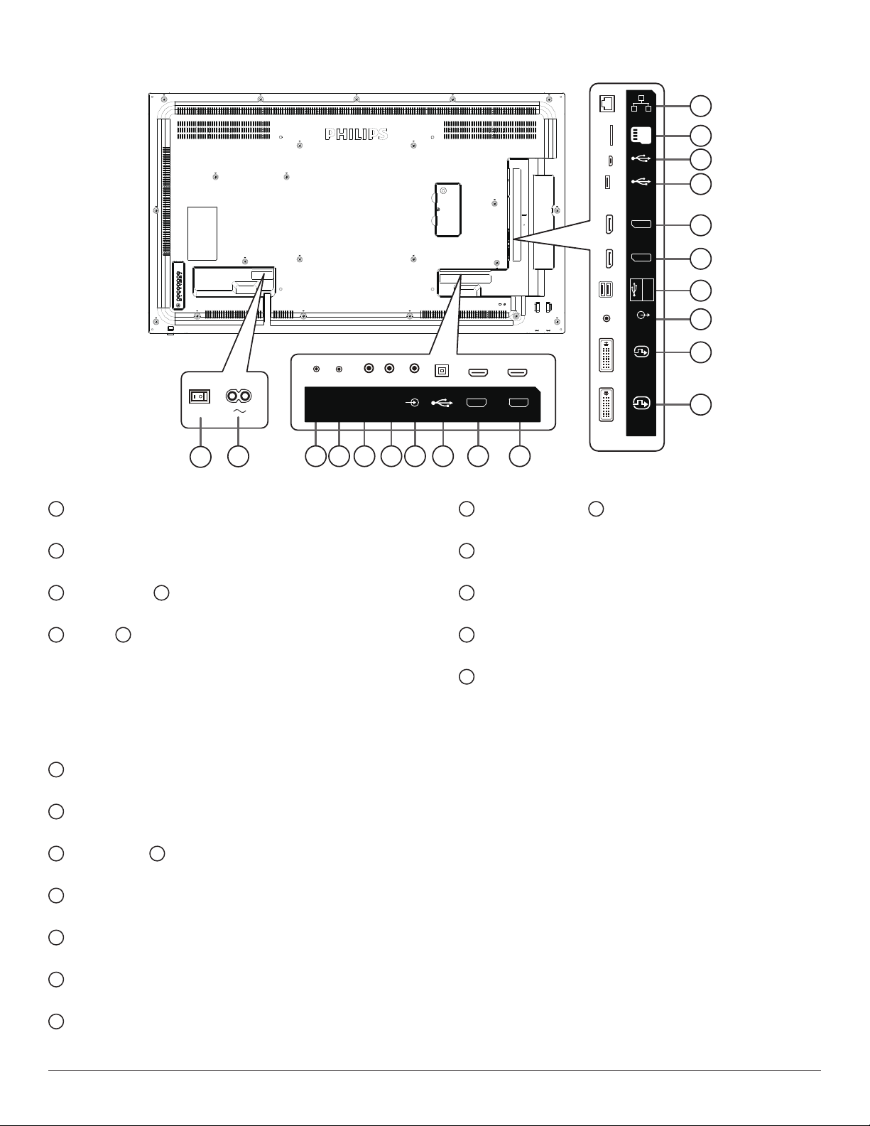
49BDL4051D
RS232
1
1
MAIN POWER SWITCH
RS232
IN
2
3 4 5 6 7 8 9 10
OUT
IR-IN IR-OUT
Switch the main power on/off.
2
AC IN
AC power input from the wall outlet.
3
RS232C IN / 4 RS232C OUT
RS232C network input / output for the loop-through function.
5
IR IN / 6 IR OUT
IR signal input / output for the loop-through function.
NOTES:
• This display’s remote control sensor will stop working if the jack
[IR IN] is connected.
• To remotely control your A/V device via this display, refer to
page 23 for IR Pass Through connection.
7
AUDIO IN
Audio input for VGA source (3.5mm stereo phone).
8
USB PORT B
Reserve for Touch model.
9
HDMI1 IN / 10 HDMI2 IN
HDMI video/audio input.
11
DVI IN
DVI-I video input.
12
DVI OUT
DVI or VGA video output.
13
AUDIO OUT
Audio output to external AV device.
14
USB PORT
Connect your USB storage device.
AUDIO
LINE-IN
MICRO SD
MICRO USB
AUDIO-LINE
USB-B
HDMI 1 IN HDMI 2 IN
15
DisplayPort IN / 16 DisplayPort OUT
DisplayPort video input / output.
17
USB PORT
Connect your USB storage device.
18
MICRO USB
Connect your USB storage device.
19
MICRO SD CARD
Connect your MICRO SD CARD.
20
RJ-45
LAN control function for the use of remote control signal from
control center for installing the optional OPS module.
RJ45
USB
DP OUT
DP IN
OUT
DVI OUT
DVI IN
20
19
18
17
16
15
USB
5V/2A
14
13
12
11
12
Page 24
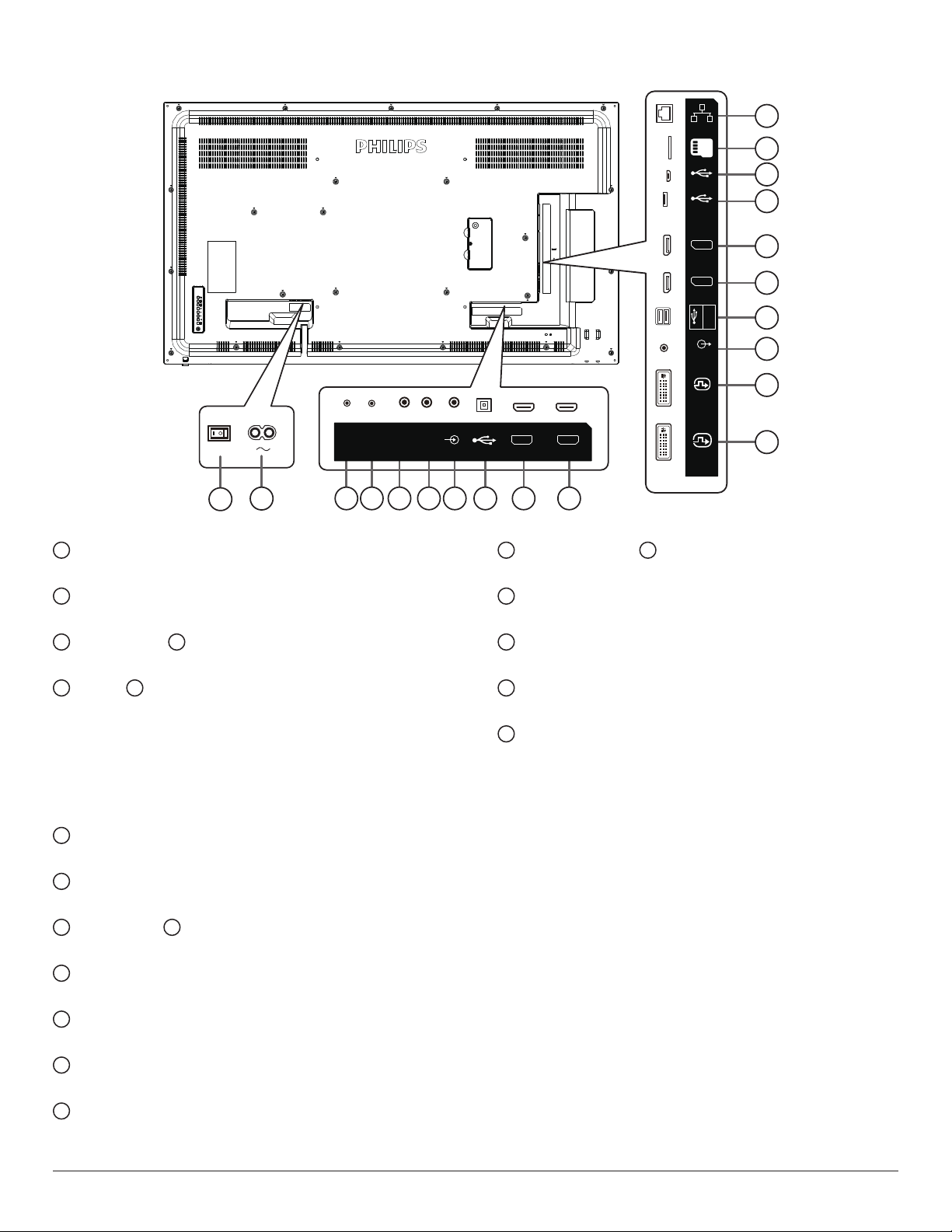
55BDL4051D
RS232
1
1
MAIN POWER SWITCH
RS232
IN
2
3 4 5 6 7 8 9 10
OUT
IR-IN IR-OUT
Switch the main power on/off.
2
AC IN
AC power input from the wall outlet.
3
RS232C IN / 4 RS232C OUT
RS232C network input / output for the loop-through function.
5
IR IN / 6 IR OUT
IR signal input / output for the loop-through function.
NOTES:
• This display’s remote control sensor will stop working if the jack
[IR IN] is connected.
• To remotely control your A/V device via this display, refer to page
23 for IR Pass Through connection.
7
AUDIO IN
Audio input for VGA source (3.5mm stereo phone).
8
USB PORT B
Reserve for Touch model.
9
HDMI1 IN / 10 HDMI2 IN
HDMI video/audio input.
11
DVI IN
DVI-I video input.
12
DVI OUT
DVI or VGA video output.
13
AUDIO OUT
Audio output to external AV device.
14
USB PORT
Connect your USB storage device.
AUDIO
LINE-IN
20
19
18
17
16
15
14
13
12
11
MICRO SD
MICRO USB
DP OUT
AUDIO-LINE
DVI OUT
USB-B
HDMI 1 IN HDMI 2 IN
15
DisplayPort IN / 16 DisplayPort OUT
RJ45
DP IN
DVI IN
USB
USB
5V/2A
OUT
DisplayPort video input / output.
17
USB PORT
Connect your USB storage device.
18
MICRO USB
Connect your USB storage device.
19
MICRO SD CARD
Connect your MICRO SD CARD.
20
RJ-45
LAN control function for the use of remote control signal from
control center for installing the optional OPS module.
13
Page 25
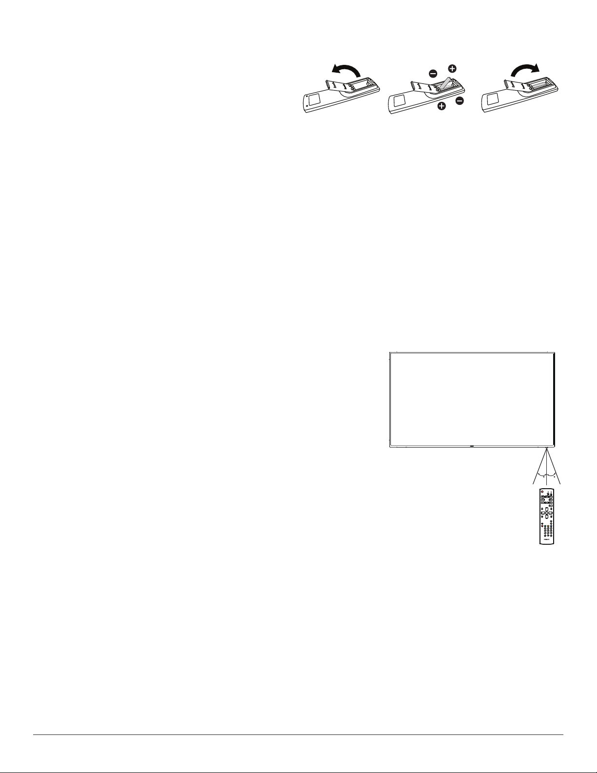
2.2.1. Inserting the batteries in the remote control
The remote control is powered by two 1.5V AAA batteries.
To install or replace the batteries:
1. Press and then slide the cover to open it.
2. Insert the batteries with the correct polarity (+) and (–).
3. Replace the cover.
Caution:
Incorrect use of batteries may cause leakage or explosion. Be sure to follow the instructions below:
• Insert “AAA” batteries with the correct polarity (+ and -).
• Do not mix battery types.
• Do not use a new battery with a used one together. Otherwise, it may cause leakage or shorten the life of the batteries.
• Remove the dead batteries immediately to avoid battery leakage in the battery compar tment. Do not touch exposed battery acid, as it may cause
injury to your skin.
NOTE: Remove the batteries from the battery compartment when not using for an extended period of time.
2.2.2. Handling the remote control
• Do not drop or apply shock to the remote control.
• Do not allow any liquid to get inside the remote control. If water has entered the remote control, wipe the remote control with a dry cloth
immediately.
• Do not place the remote control near heat and steam sources.
• Do not attempt to disassemble the remote control, unless you need to place batteries in the remote control.
2.2.3. Operating range of the remote control
Point the top front of the remote control at the remote sensor on the display when you press the
buttons.
Use the remote control within a distance of less than 5m/16ft from the display’s sensor, and a
horizontal and vertical angle of less than 30°.
NOTE:
1. The remote control may not function properly when the remote control sensor on the display
is under direct sunlight or strong illumination, or when there is an object between the remote
control and the remote sensor of the display.
2. Push out the lens to have better remote control performance and easy to observe the light
information of power status.
3. Pull back the lens before mounting the display for video wall application.
4. Pull/Push the lens until hearing the click sound.
3030
14
Page 26
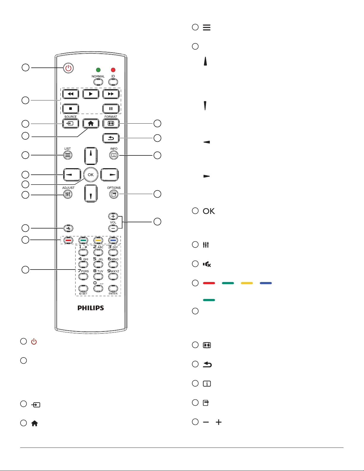
2.3. Remote Control
2.3.1. General functions
5
[ ] LIST button
Reserved.
6
NAVIGATION buttons
10
11
1
[ ]
Root Menu: Go to the OSD of Smart picture.
Main Menu: Move the selected item up to make adjustment.
IR Daisy Chain Menu: Increase the controlled Group ID number.
2
3
4
5
12
13
14
6
7
8
15
16
9
[ ]
Root Menu: Go to the OSD of Audio source.
Main Menu: Move the selected item bar down to make adjustment.
IR Daisy Chain Menu: Decrease the controlled Group ID number.
[ ]
Main Menu: Go to the previous level of menu.
Source Menu: Exit from the source menu.
Volume Menu: Decrease the volume.
[ ]
Main Menu: Go to the next level of menu or set selected option.
Source Menu: Go to the selected source.
Volume Menu: Increase the volume.
7
[ ] button
Root Menu: Go to the OSD of IR daisy chain in Primary/Secondary
mode.
Main Menu: Conrm an entry or selection.
8
[ ] ADJUST button
Go to the OSD of Auto Adjust (for VGA only).
9
[ ] MUTE button
Sound mute on or off.
10
[ ] [ ] [ ] [ ] COLOR buttons
Choose a task or option. (for Media Input only)
[ ]
Hot key for Window selection function.
1
[ ] POWER button
Turn the power On/Off.
2
[PLAY] buttons
Control playback of media les.(for Media Input only)
Freeze feature
Pause: hot key for freezing all inputs content.
Play: hot key for unfreezing all input content.
3
[ ] SOURCE button
Root Menu: Go to the OSD of Video source.
4
[ ] HOME button
Root Menu: Go to the OSD of Main Menu.
Others: Exit from the OSD.
15
11
[Number/ ID SET/ ENTER] button
Enter text for network setting.
Press to set the display ID. Refer to 2.3.2. ID Remote Control
for more details.
12
[ ] FORMAT button
Change Image Zoom Mode [Full][4:3][1:1][16:9][21:9][Custom].
13
[ ] BACK button
Return to the previous page or exit from the previous function.
14
[ ] INFO button
Show Information OSD.
15
[ ] OPTIONS button
Reserved.
16
[ ] [ ] VOLUME button
Adjust volume level.
Page 27
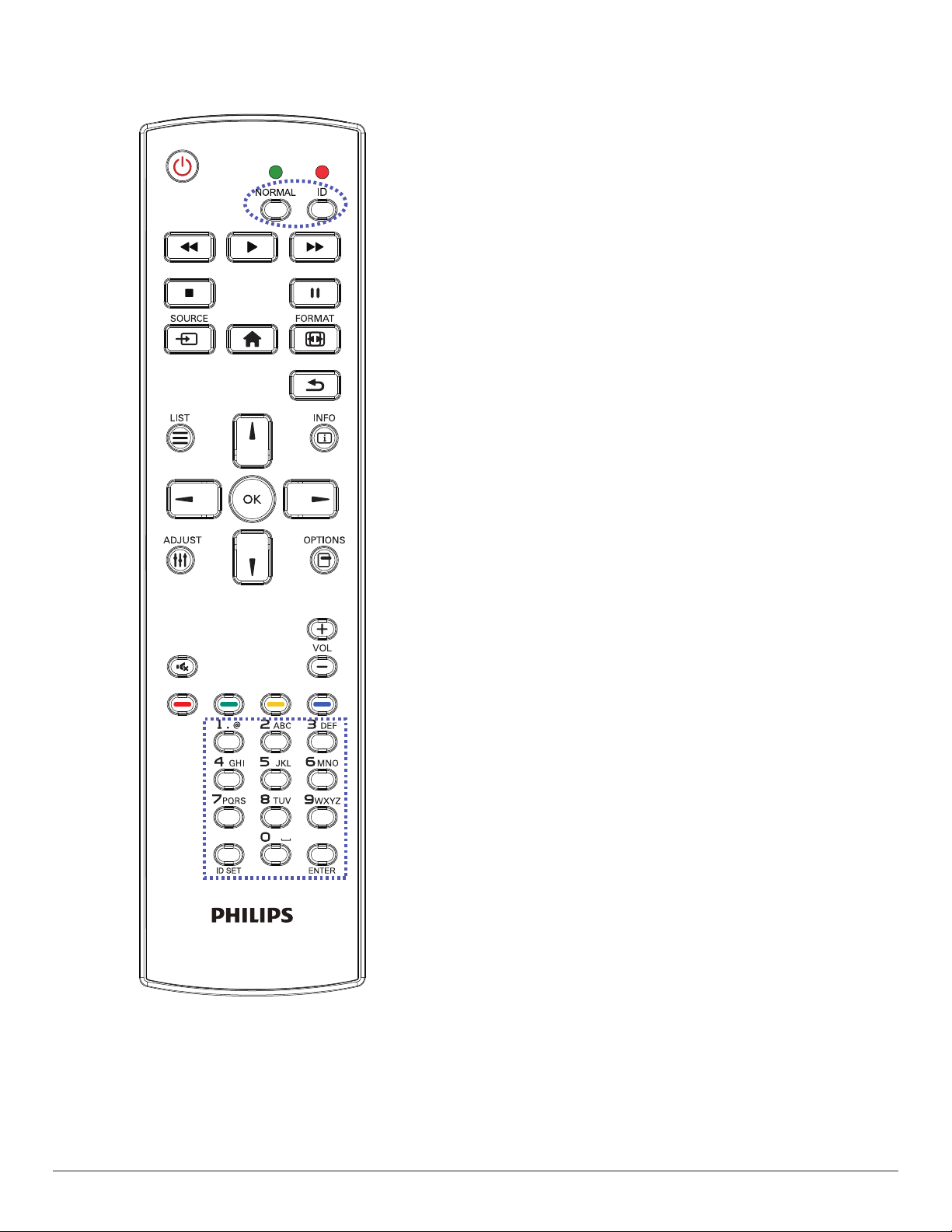
2.3.2. ID Remote Control
Set remote control ID number when using several displays.
Press the [ID] button and the red LED blinks twice.
1. Press [ID SET] button for more than 1 second to enter the ID
Mode. The red LED lights up.
Press the [ID SET] button again will exit the ID Mode. The red LED
lights off.
Press the digit numbers [0] ~ [9] to select the display to be controlled.
For example: press [0] and [1] for display No.1, press [1] and [1] for
display No.11.
The numbers available are [01] ~ [255].
2. If no button is pressed within 10 seconds, it will exit from the ID
mode.
3. If a wrong button is pressed, wait for 1 second until the red LED
lights off and then turns on again, then press the correct digits.
4. Press [ENTER] button to conrm your selection. The red LED blinks
twice and then lights off.
NOTE:
• Press [NORMAL] button. The green LED blinks twice, indicating that
the display is under normal operation.
• It is necessary to set up the ID number for each display before
selecting its ID number.
16
Page 28
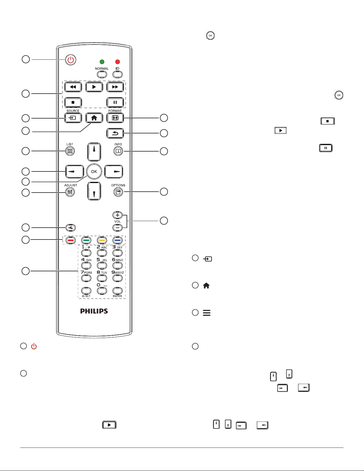
2.3.3. Remote Control buttons on Android
source
1
2
3
4
12
13
3)Media Player -> Play -> choose non-empty play list -> press
to play all media les from the playlist.
4) Set media playlist in Boot on Source or Schedule by OSD
menu.
2. Play the PDF le
There are 3 ways to play the PDF les.
1) File Manager
Find the PDF le from the File Manager and select it to play.
2) PDF Player -> Play -> choose non-empty play list -> press
to play all PDF les from the playlist.
3) Set pdf playlist in Boot on Source or Schedule by OSD menu.
3. When playing a PDF, video or music le, you can press
button to stop playing. If you press again, playback will be
started from the beginning of the le.
10
11
5
14
6
7
8
15
16
9
4. When playing a PDF, video or music le, you can press
button to pause playing.
5. All media or PDF les should be located in the folder of “philips”,
under the root directory of the specied storage (internal/USB/SD
Card). All sub-folders (video/photo/music/pdf) are named by media
types and shouldn’t be changed.
videos: {root dir of storage}/philips/video/
photos: {root dir of storage}/philips/photo/
music : {root dir of storage}/philips/music/
pdfs : {root dir of storage}/philips/pdf/
Note that the root directories of three storages are
Internal storage: /sdcard
USB storage: /mnt/usb_storage
SD card : /mnt/external_sd
3
] SOURCE button
[
Select an input source.
The button is only controlled by Scalar.
4
[ ] HOME button
Access the OSD menu.
The button is only controlled by Scalar.
5
[ ] LIST button
1
[ ] POWER button
Turn the display On or turn the the display to standby mode.
The button is only controlled by Scalar.
2
[PLAY] buttons
1. Control playback of media (video/audio/picture) les.
There are 4 ways to play the media les.
1) File Manager
Find the media le from the File Manager and select it to play.
2) Media Player -> Compose -> edit or new add playlist ->
choose any media les -> press button to play the media
le directly.
17
1. In the content of the web page, move the focus up to the next
selectable items.
2. Move the focus up to the next control or widget such as buttons.
6
NAVIGATION buttons
1. Navigate through the menus and select an item.
2. In the content of the web page, these buttons are for controlling
the scroll bar of the screen. Press or for moving the
vertical scroll bar up or down. Press or for moving the
horizontal scroll bar left or right.
3. For PDF les,
»when zoom in/out is performed,
Press , , or to adjust the position of the
screen.
»when zoom in/out is not performed,
Page 29
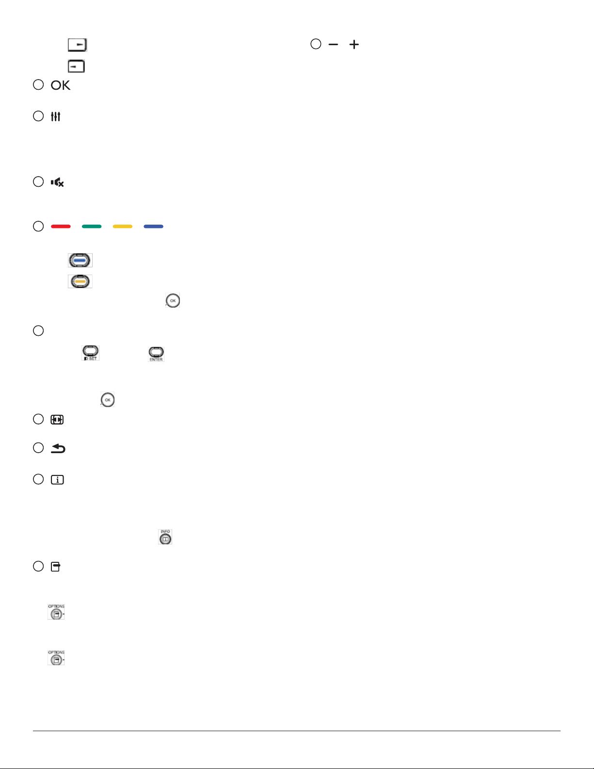
Press to go to the next page.
Press to go to the previous page.
7
[ ] button
Conrm an entry or selection.
8
[ ] ADJUST button
1. In the content of the web page, move the focus down to the next
selectable items.
2. Move the focus down to the next control or widget such as
buttons.
9
[ ] MUTE button
Sound mute on or off.
The button is only controlled by Scalar.
10
[ ] [ ] [ ] [ ] COLOR buttons
1. For PDF les,
press button to perform zoom-in;
press button to perform zoom-out.
After zoom-in or zoom-out, press button to revert the PDF
le to the original size.
11
[Number/ ID SET/ ENTER] button
16
[ ] [ ] VOLUME button
Adjust volume level. The buttons are only controlled by Scalar.
1. ID SET and ENTER have no function on Android
source. These buttons are only controlled by Scalar.
2. For PDF le, enter the page number by pressing number buttons
and then press button to enter the specied page.
12
[ ] FORMAT button
Change picture format. The button is only controlled by Scalar.
13
[ ] BACK button
Return to the previous page or exit from the previous function.
14
[ ] INFO button
1. Display information about the current input signal. It is shown by
Scalar.
2. Media Player -> Compose -> edit or add a new playlist ->
choose any media les -> press to show the information of
the selected media le.
15
[ ] OPTIONS button
Open the toolbox from Media Player or PDF Player.
1. Media Player ->Compose -> Edit or add a new playlist -> press
to open a toolbox. The toolbox will slide from the left side of
the screen.
2. PDF Player ->Compose -> Edit or add a new playlist -> press
to open a toolbox. The toolbox will slide from the left side
of the screen.
18
Page 30
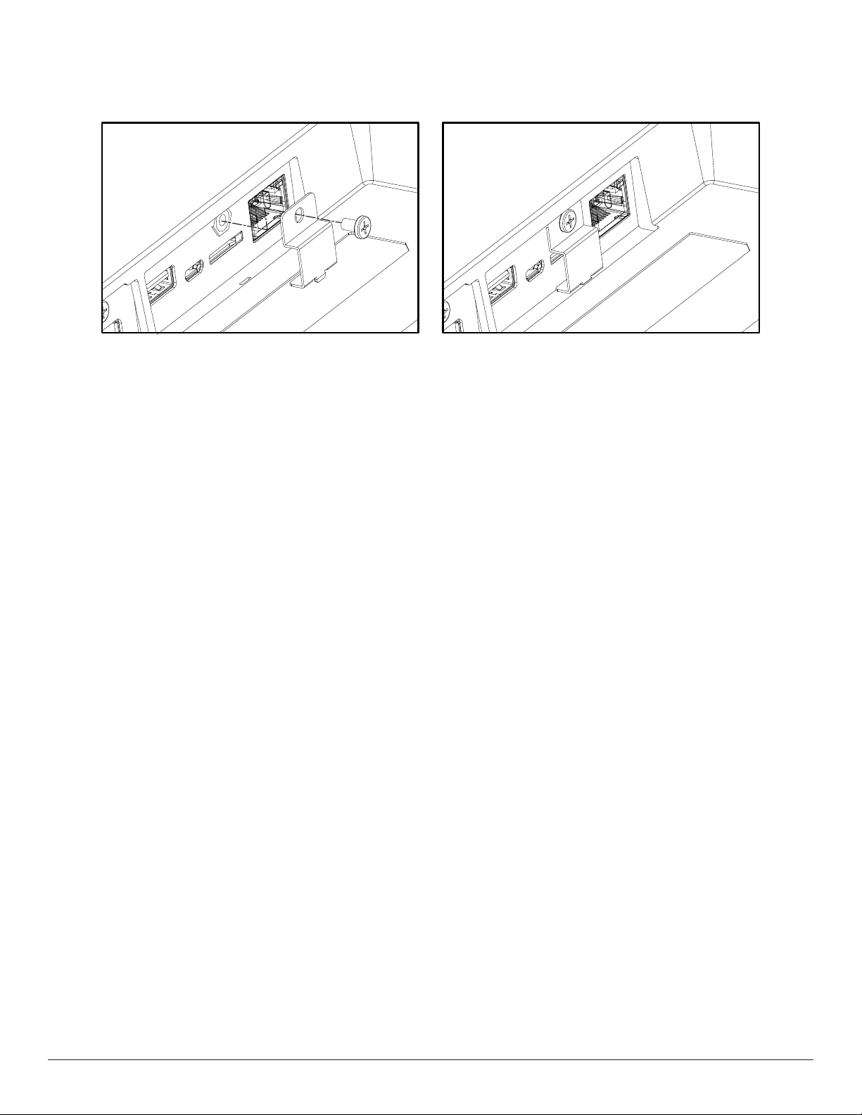
2.4. SD card Cover
• Use the SD card cover and screws to cover the Micro SD card.
19
Page 31
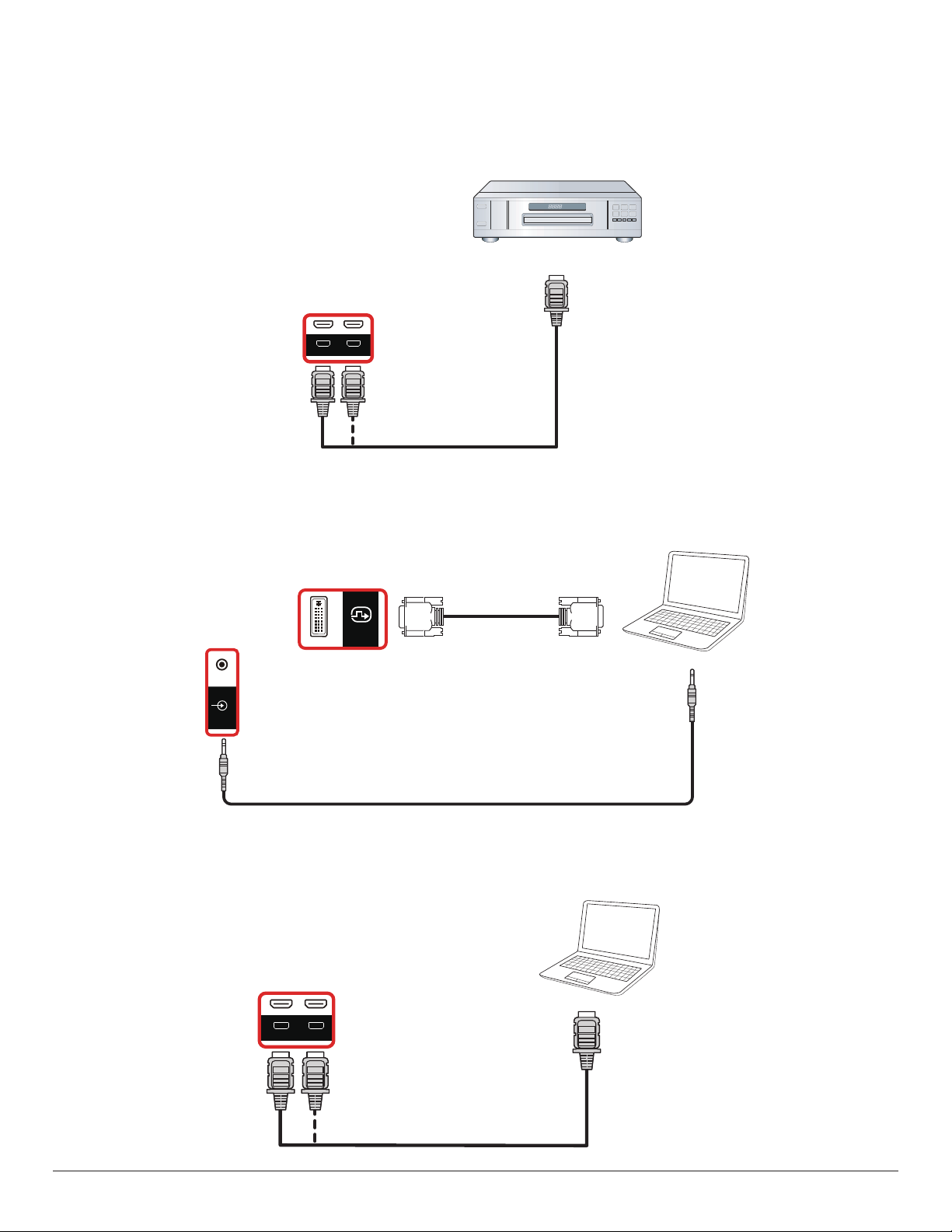
3. Connecting External Equipment
AUDIO
LINE-IN
USB-B
HDMI 1 IN HDMI 2 IN
DVI OUT
3.1. Connecting External Equipment (DVD/VCR/VCD)
3.1.1. Using HDMI video input
DVD / VCR / VCD
3.2. Connecting a PC
3.2.1. Using DVI input
HDMI1 IN
HDMI2 IN
DVI IN
[HDMI IN]
[DVI IN]
HDMI Out
DVI Out
Audio Out
PC
3.2.2. Using HDMI input
[VGA AUDIO IN]
HDMI2 IN
HDMI1 IN
PC
HDMI Out
[HDMI IN]
20
Page 32
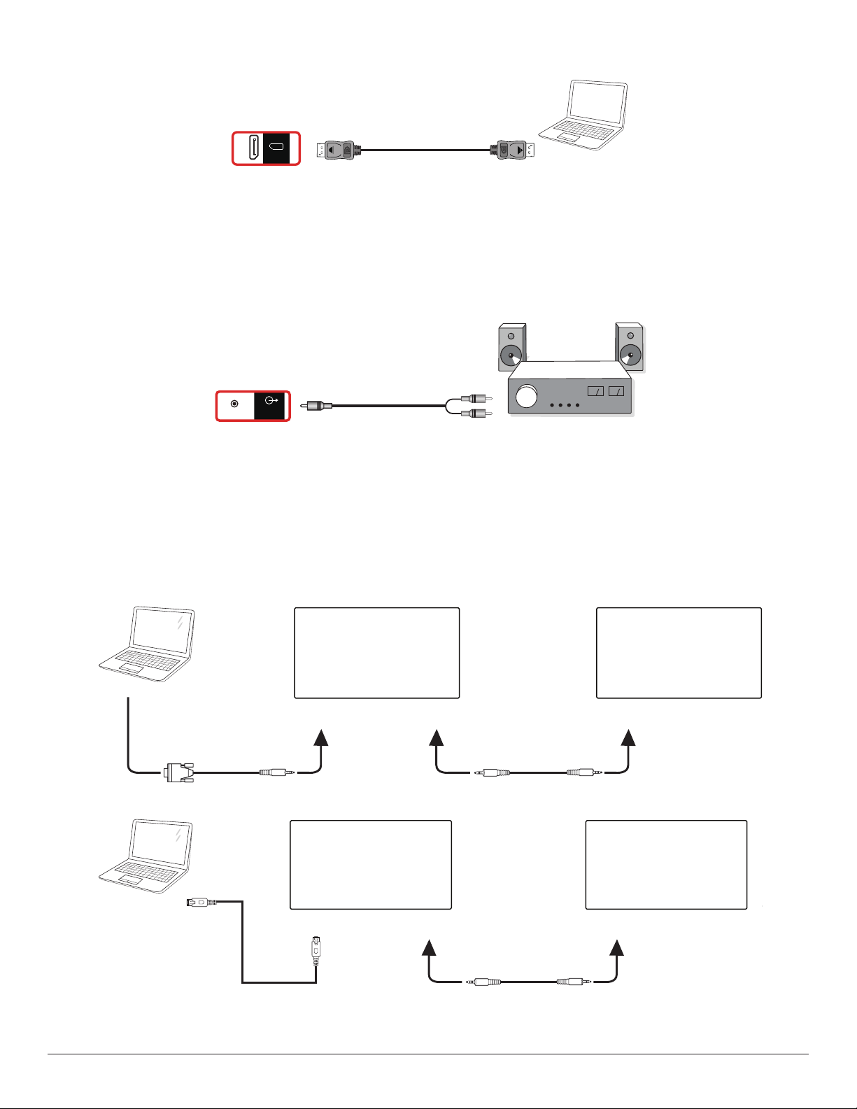
3.2.3. Using DisplayPort input
USB
5V/2A
PC
[DisplayPort IN]
DP IN
DisplayPort Out
3.3. Connecting Audio Equipment
3.3.1. Connecting an external audio device
Audio In
AUDIO-LINE
OUT
[AUDIO OUT]
Stereo Amplifier
3.4. Connecting Multiple Displays in a Daisy-chain Configuration
You can interconnect multiple displays to create a daisy-chain conguration for applications such as a menu board.
3.4.1. Display control connection
Connect the [RS232 OUT] connector of DISPLAY 1 to the [RS232 IN] connector of DISPLAY 2.
DISPLAY 1
PC
PC
[RS-232C]
[RJ-45]
[RS-232C IN]
[RS-232C OUT] [RS-232C IN]
DISPLAY 1 DISPLAY 2
[RJ-45] [RS-232C OUT] [RS-232C IN]
DISPLAY 2
21
Page 33
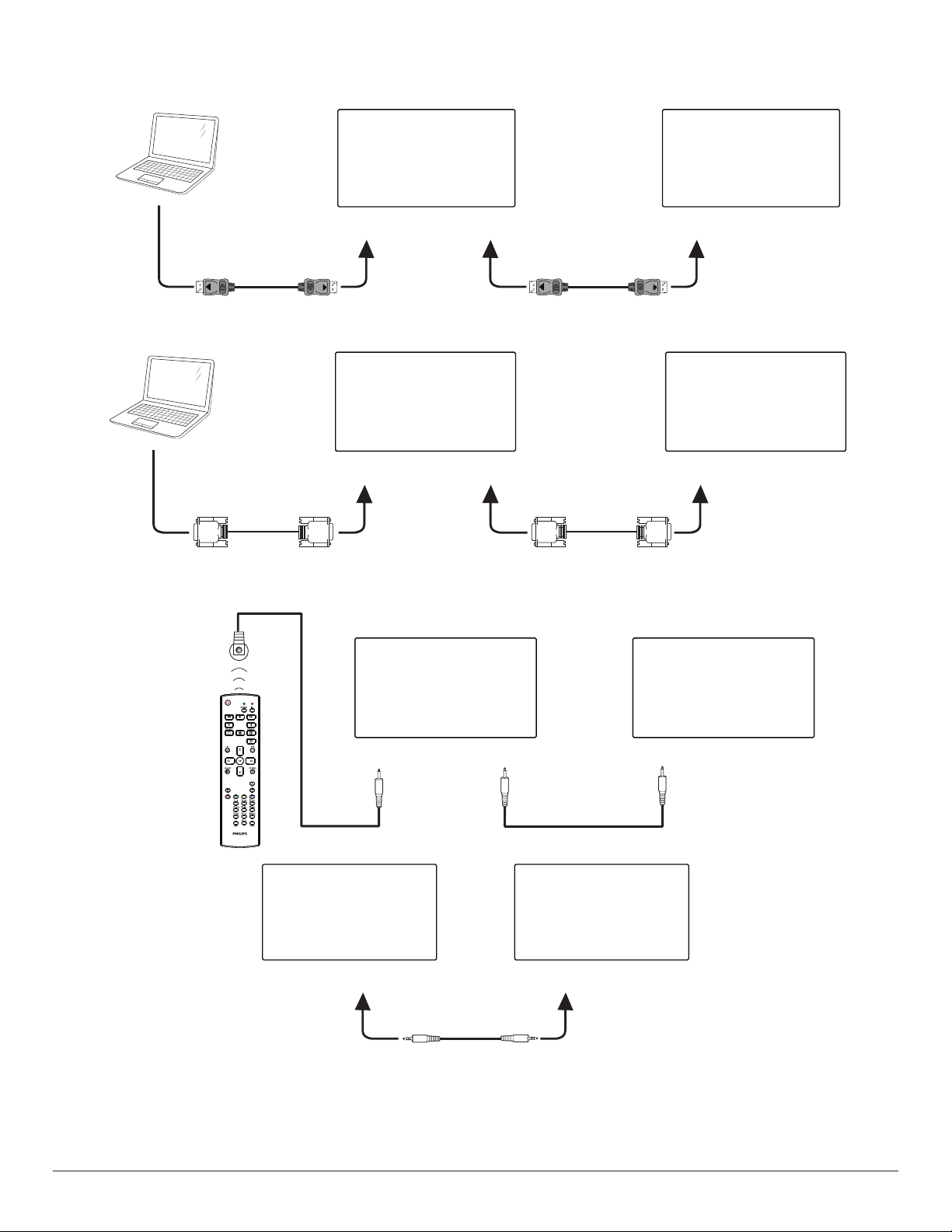
3.4.2. Digital video connection
Connect the [DP OUT] connector of DISPLAY 1 to the [DP IN] connector of DISPLAY 2.
DISPLAY 1 DISPLAY 2
PC
[DP]
[DP IN]
Connect the [DVI OUT] connector of DISPLAY 1 to the [DVI IN] connector of DISPLAY 2.
DISPLAY 1 DISPLAY 2
PC
[DVI]
[DVI IN]
[DP OUT] [DP IN]
[DVI OUT] [DVI IN]
3.5. IR connection
External
IR Receiver
DISPLAY 1 DISPLAY 2
[IR IN]
DISPLAY 1 DISPLAY 2
[RS-232C OUT] [RS-232C IN]
[IR OUT]
[IR IN]
NOTE:
1. The remote control sensor of this display will stop working if the [IR IN] is connected.
2. IR loop through connection can support up to 9 displays.
3. IR in daisy chain via RS232 connection can support up to 9 displays.
22
Page 34
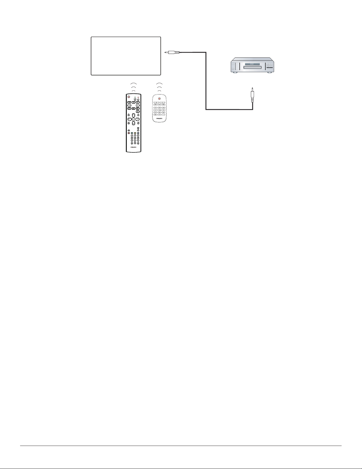
3.6. IR Pass-through Connection
[IR OUT]
DVD / VCR / VCD
[IR IN]
(DVD / VCR / VCD)
Remote Control
23
Page 35
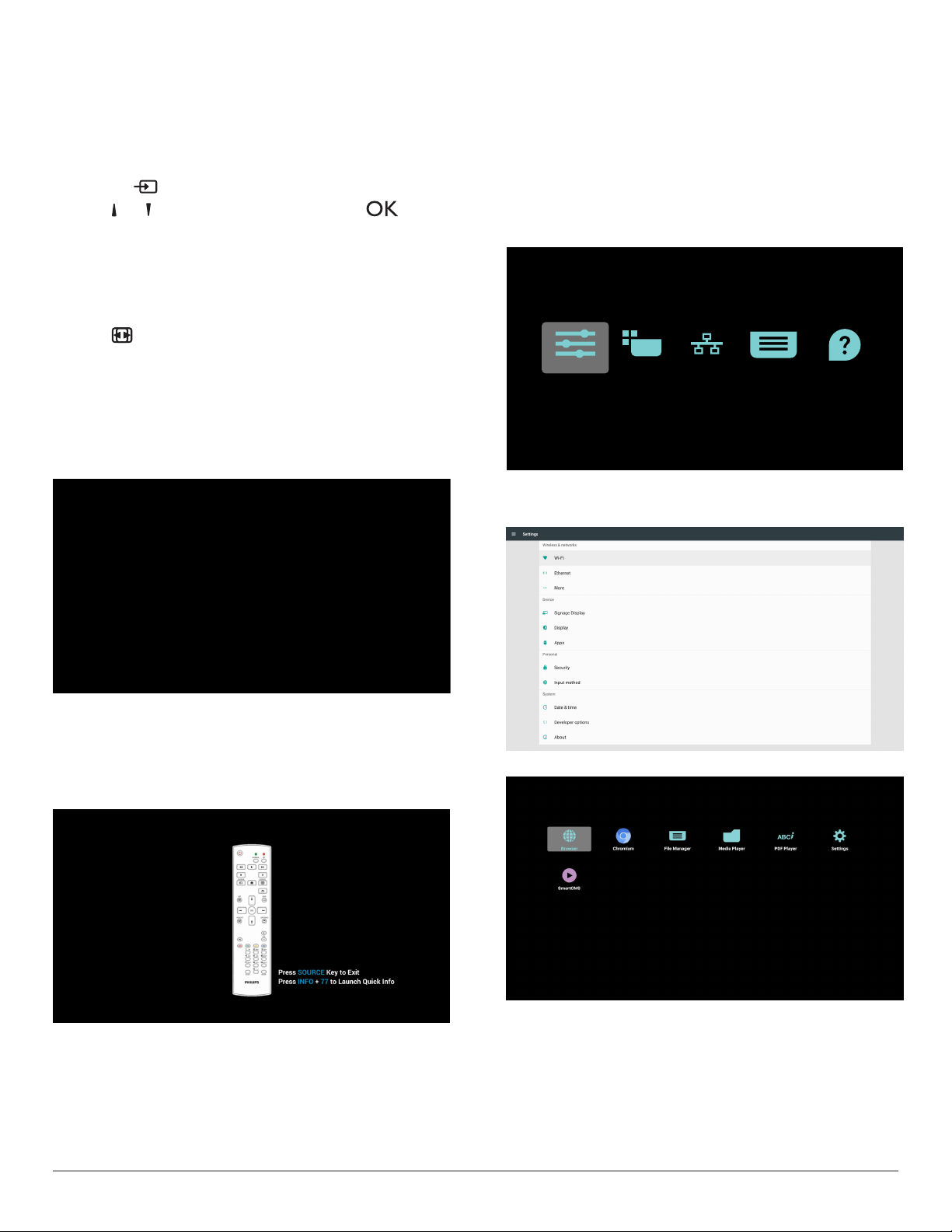
4. Operation
Settings Apps Network Storage Help
NOTE: The control button described in this section is mainly on the
remote control unless specied otherwise.
4.1. Watch the Connected Video Source
1. Press the [ ] SOURCE button.
2. Press [ ]
4.2. Change Picture Format
You can change the picture format to suit the video source. Each video
source has its available picture formats.
The available picture formats depend on the video source:
1. Press [ ] FORMAT button to select a picture format.
• PC mode: {Full} / {4:3} / {Real} / {21:9}/ {Custom}.
• Video mode: {Full} / {4:3} / {Real} / {21:9}/ {Custom}.
4.3. Overview
1. Android PD launcher:
• Android PD launcher is a black page as shown below:
or [ ] button to select a device, then press [ ] button.
• When leaving from the Admin mode, the system will return to
last source.
Home page of Admin mode, this page consists of the following
itmes: “Settings”, “Apps”, “Network” “Storage” and “Help”.
Settings: go to Settings page.
Applications: show all apps.
Network: set Wi-Fi, Ethernet and Mobile network (optional).
Storage: go to Storage page.
Help: display QR code.
1) Settings page:
Settings: go to Settings page.
Signage Display: go to signage display settings page.
• Exit the App by pressing the “Back” key and the screen will
enter Android PD launcher.
• When you return to Android PD launcher, a hint image will be
prompted on the screen for 5 seconds.
• The hint image noties you that you can press source key to
change source.
2. Admin mode:
• Press “Home + 1888” to enter the Admin mode. Please
make sure that you see the Home OSD menu after “Home”
is pressed, and then press 1888 in sequence. Two continuous
“Home” keys will not be a valid hotkey.
• The Admin mode consists of the following Apps: “Settings”,
“Apps”, “Network” “Storage” and “Help”.
2.) Application page:
24
Page 36
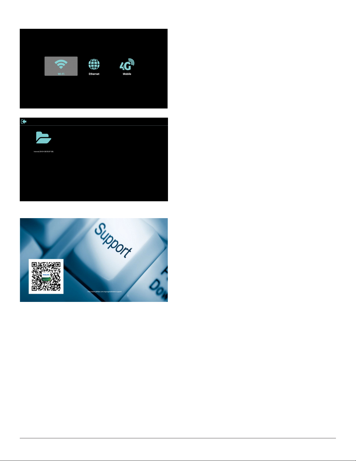
3) Network page
4) Storage page
5) Help page
Display QR to link to Philips support website.
25
Page 37
4.4. Media Player
4.4.1. OSD menu interaction with media player:
1. Boot on source:
- Input:
■ If you select Media player as the source, the system will
enter media player automatically after the boot process is
completed.
- Playlist:
■ 0: go to the main page of media player.
■ 1 - 7: go to media player and playback File1 - File7 of playlist
automatically.
2. Schedule:
- Today:
■ Show date and time.
- ☐1 - ☐7:
■ Set up to 7 schedules.
- On/Off:
■ Set start time and end time.
- Input:
■ Select Media player as the source, the PD will launch the
media player automatically at end time.
- MON, TUE, WED, THU, FRI, SAT,SUN, Every week :
■ Set life cycle.
- Play list :
■ 0: go to the main page of media player.
■ 1 - 7: go to media player and playback File1 - File7 of the
playlist automatically.
- Clear all
4.4.2. Media Player introduction:
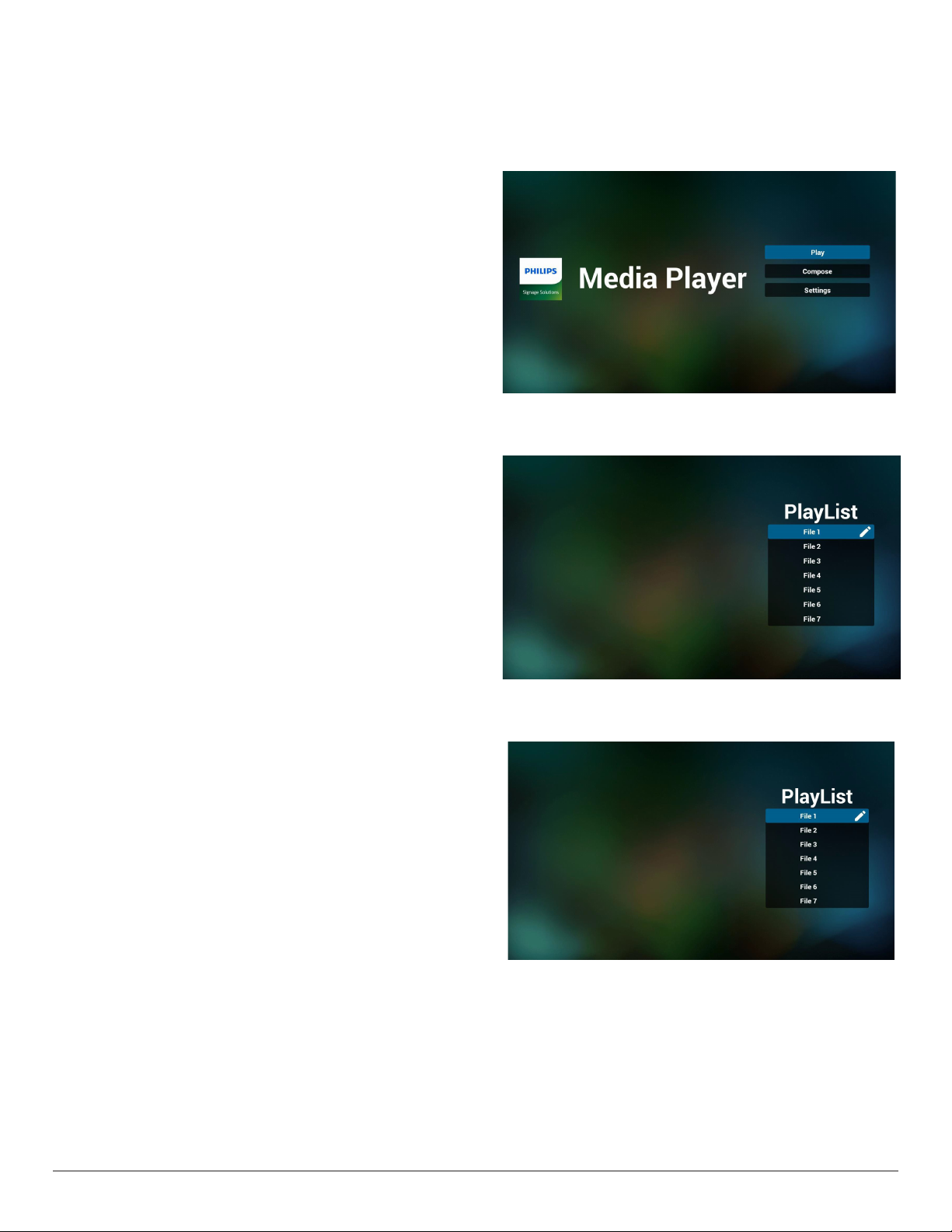
1. The main page of Media Player, this page consists of three options:
“Play”, “Compose” and “Settings”.
Play: select a playlist to play.
Compose: edit a playlist.
Settings: setting the properties of Media Player.
2. Select “Play” on the main page, rst you should choose one playlist
to play between FILE 1 and FILE 7.
The pencil icon means that the playlist contains the content.
3. Select “Compose” on the main page, rst you should select one
playlist to edit between FILE 1 and FILE 7.
The pencil icon means that the playlist contains the content.
4. If an empty playlist is selected, the App will guide you through
selecting the media source.
All media les should be stored in /philips/ of root directory.
For example,
videos: {root dir of storage}/philips/video/
photos: {root dir of storage}/philips/photo/
music : {root dir of storage}/philips/music/
26
Page 38
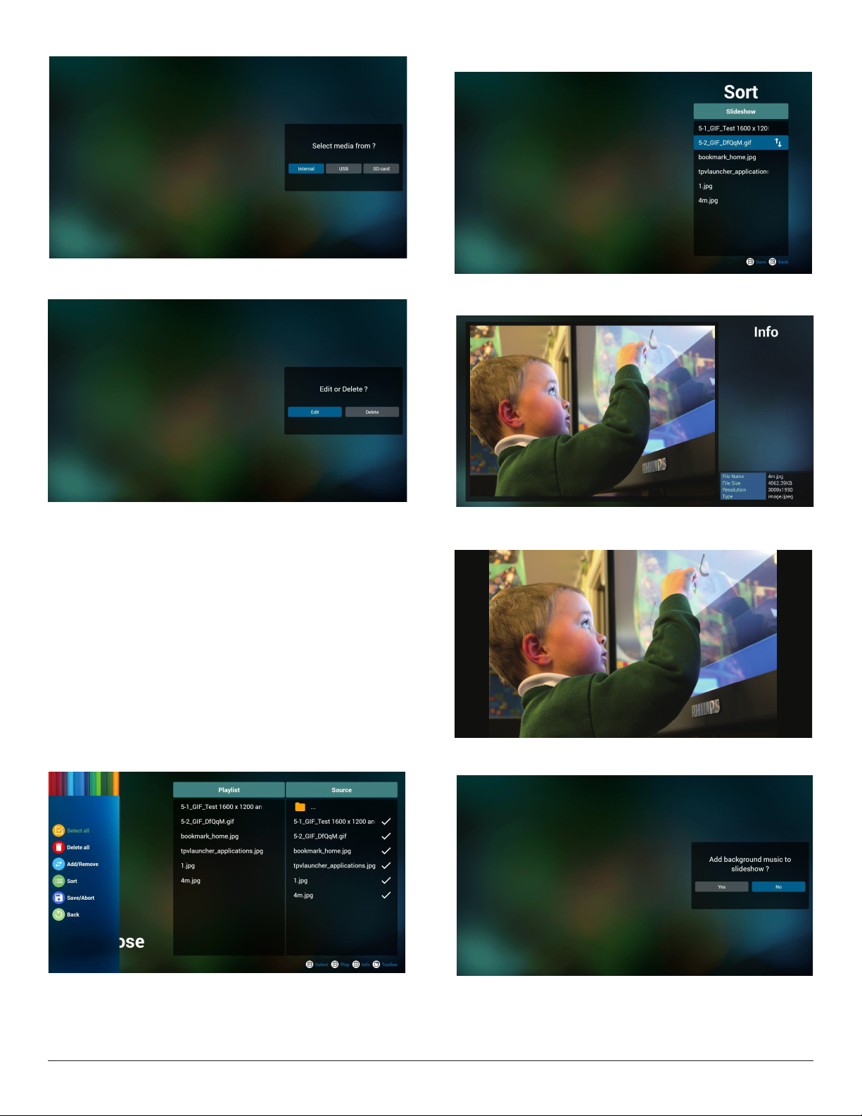
5. To edit or delete a non-empty playlist, select the desired playlist that
has a pencil icon on right side of the le.
7. If “Sort” is selected, you can customize the le order severally.
8. After selecting the desired le, press “Info” key to obtain the
detailed information.
6. Once you start to edit a playlist, a menu is displayed as below.
Source - les saved in the memory storage.
Playlist – les saved in the playlist.
The following functions can be operated through the corresponding
keys on the remote control.
Option key – launch the side menu bar
Play key – play the media le.
Info key – show the media info.
Ok key – select/deselect a le.
From the side menu bar, the following functions are available:
- Select all: select all les saved in the storage.
- Delete all: delete all playlist les.
- Add/Remove: add or remove a playlist from source.
- Sort: sort the playlist.
- Save/abort: save or abort the playlist.
- Back: return to the previous menu.
9. After selecting the desired le, press “Play” key to play the media le
immediately.
10. If you create a playlist with all image les, you will be asked to add a
background music to the slideshow before saving.
27
Page 39
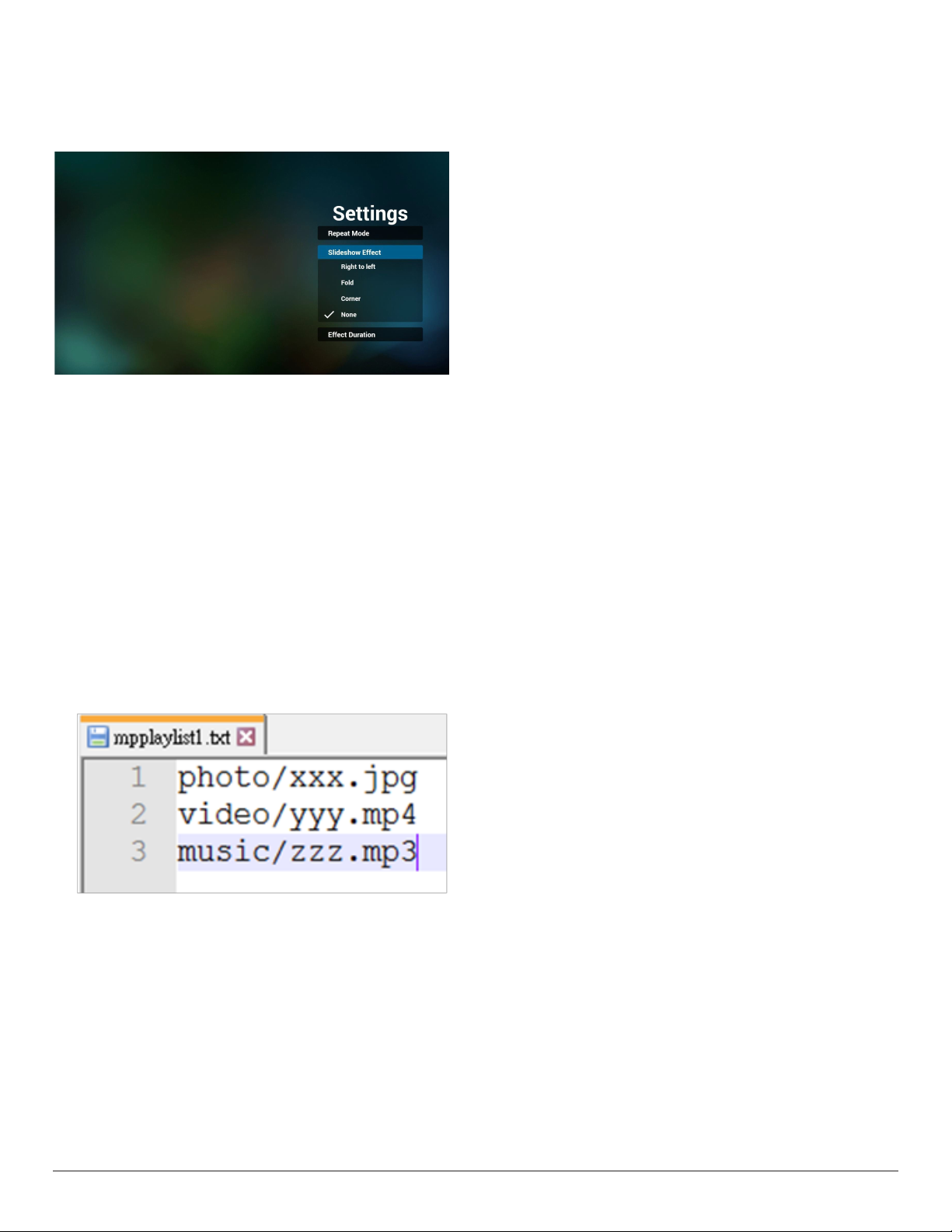
11. Select “Settings” on the main page, there are 3 options available:
“Repeat Mode”, “Slideshow Effect” and “Effect Duration”.
Repeat Mode: set the repeat mode.
Slideshow Effect: photo slideshow effect.
Effect Duration: duration of photo effect.
12. Media Hotkey
Play: play the le.
Pause: pause.
Fast forward: fast forward for 20 seconds. (photo mode is not
supported)
Rewind: rewind for 10 seconds. (photo mode is not supported)
Stop: stop playing the le and return to start. If the le being played
is a “gif ” le, it will act as a pause key.
Step 4. Start media player App, it will import the text le of media
player automatically.
Note. Once the playlist le (text) is imported, any changes made
through the remote control will not be recorded in the playlist text
le.
13. Media format please refer to Page 56 Supported Media Formats.
14. How to edit the playlist via FTP.
Step 1. Create a text le of media player.
- File name : mpplaylistX.txt, “X” means playlist
number(1,2,3,4,5,6,7).
Ex. mpplaylist1.txt, mpplaylist2.txt
- Content :
Note: If a playlist contains both video and music les, a black screen
will display when the system plays the music le.
Step 2. Copy “mpplaylistX.txt” to “philips” folder of the internal
storage. You may use FTP to do this.
- File path : /storage/emulated/legacy/philips
Ex. /storage/emulated/legacy/philips/mpplaylist1.txt
Step 3. Add the media les in “photo”, “video” and “music” folders
which are under “philips” folder of your internal storage.
- Ex. /storage/emulated/legacy/philips/photo/xxx.jpg
/storage/emulated/legacy/philips/video/yyy.mp4
/storage/emulated/legacy/philips/photo/zzz.mp3
28
Page 40
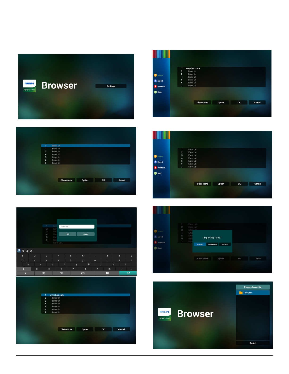
4.5. Browser
Before using this feature, ensure that the system is connected
successfully to the network. (See 5.1. Wi-Fi & 5.2. Ethernet)
1. Main page of “Browser” App which allows you to make related
settings.
Press Settings to make the settings.
4. From the side menu bar on left side of the screen, the following
functions are available:
Import: Import the le of URL list
Export: Export the le of URL list
Delete all: Delete all URL records from the main screen
Back: Close the side menu bar
2. Up to 7 browsers can be set. Select one to make the settings.
3. Use the on-screen keyboard to enter URL and press the OK
button, the data will be saved in the List
4.1 Import
• Select import.
• Select the storage where the le will be imported from.
• Select a browser le
29
Page 41
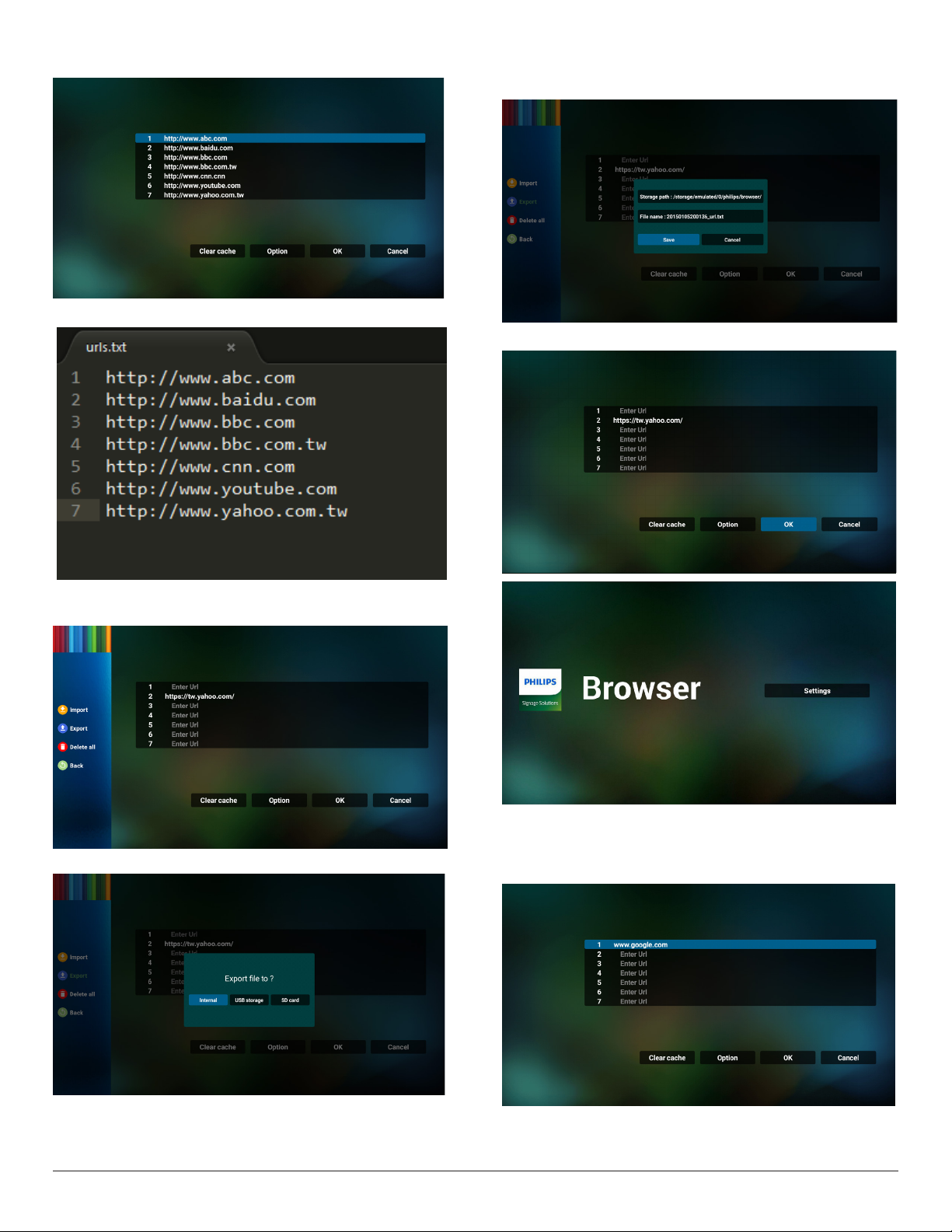
• Import the browser le and the URL will be listed on the screen.
• The le format supported for import is “.txt”.
• A dialog box displays the path of the le to be saved as well as the
le name. Press the “Save” button to save the URL.
5. Press the “OK” button to save the URL record.
4.2 Export:
• Select export
• Select the storage where the le will be exported to.
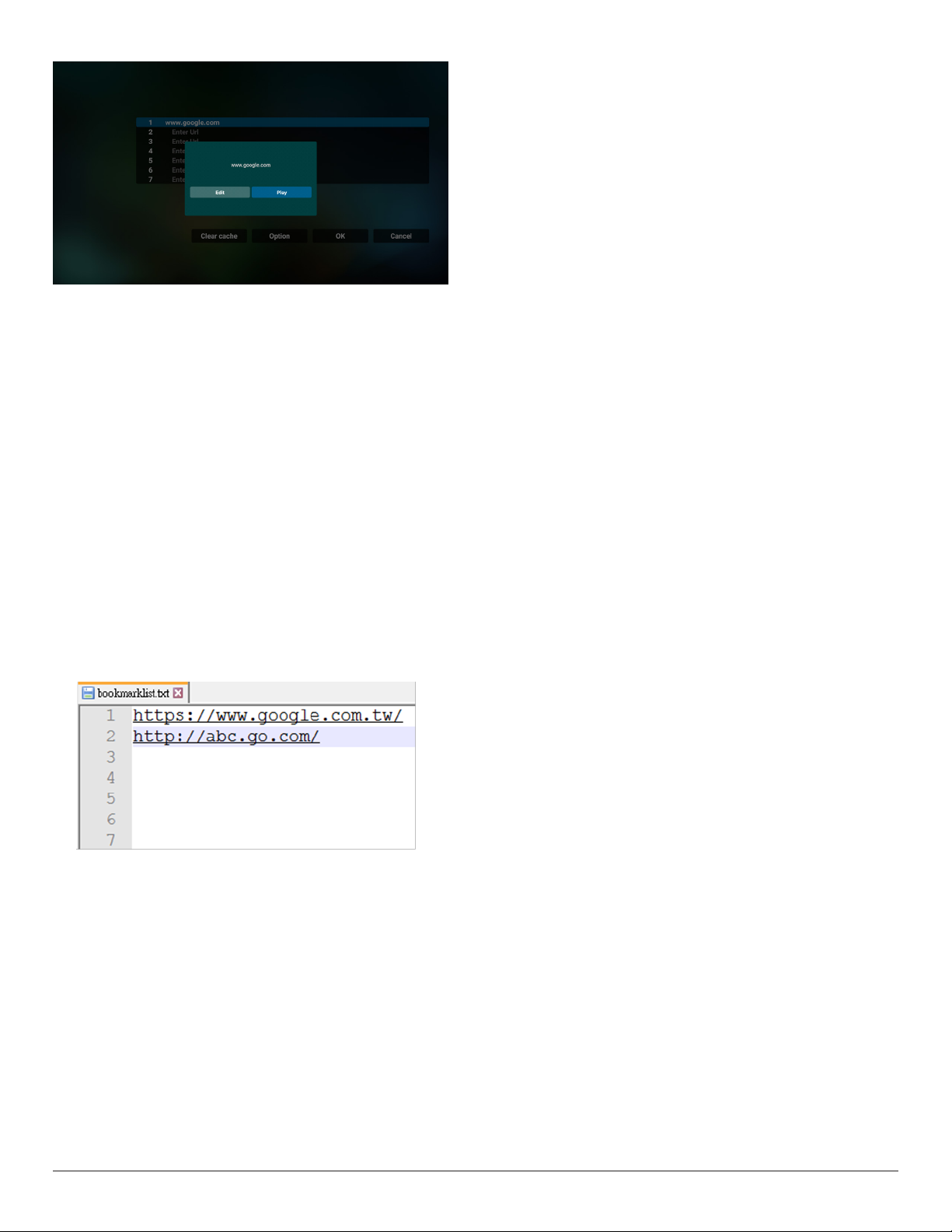
6. If you select a non-empty item from the URL list, a message will
appear asking if you want to edit or play the URL. If you select “Edit”
a dialog box allows you to edit the URL. If you select “Play”, a web
page of the selected URL appears.
30
Page 42
7. OSD menu interaction with Browser
7.1 Boot on source
• Set OSD menu > Conguration1 > Boot on source > set
BROWER Play List to 0.
Then PD will show Browser after rebooting.
• Set OSD menu > Conguration1 > Boot on source > set
BROWER Play List to 1.
The web page of the rst URL from Browser App will be shown on
the screen.
7.2 Schedule
Set OSD menu > Advanced option > Schedule >
On time1, Off time2, Input BROWSER, the desired day you of the
week, and the Playlist.
Finally check the right box.
The web page of the URL from Browser App will be shown on the
screen at time1 and nished at time2.
8. How to edit url list via FTP
Step 1. Create a text le of media player.
- File name: bookmarklist.txt.
- Content:
If network is disconnected while osd schedule opens browser app,
browser app will automatically open Url 1 address home page in
local storage.
Note:
a. Browser app can only save Url 1 address home page data, other
Url 2 to Url 7 cannot be saved.
b. Local storage : /sdcard/Download/OfineBrowsing
c. Pressing “Clear cache” button can clear Url 1 address home page
data from local storage.
Step 2. Copy bookmarklist.txt to “philips” folder of your internal
storage. You may use FTP to do this.
- File path: /storage/emulated/legacy/philips (for DL, PL)
Ex. /storage/emulated/legacy/philips/bookmarklist.txt
Step 3. Start Browser App, it will impor t the text le of Browser
automatically.
Note. Once the playlist le (text) is imported, any changes made
through the remote control will not be recorded in the playlist text
le.
9. Ofine browsing
When Url 1 has set address, and use osd schedule to open Url 1
web page, browser app will automatically save home web page data
of Url1 to local storage.
31
Page 43
4.6. PDF Player
4.6.1. OSD menu interaction with PDF player:
1. Boot on source:
- Input:
■ If you select “PDF player” as the source, the system will
launch PDF player automatically after the boot process is
completed.
- Playlist:
■ 0: go to the main page of PDF player.
■ 1 - 7: go to PDF player and playback File1 - File7 of the
playlist automatically.
2. Schedule:
- Today :
■ Show date and time.
- ☐1 - ☐7 :
■ Set up to 7 schedules.
- On/Off :
■ Set start time and end time.
- Input :
■ Select PDF player as the source, the system will launch the
PDF player automatically at end time.
- MON, TUE, WED, THU, FRI, SAT,SUN, Every week :
■ Set life cycle.
- Play list :
■ 0: go to the main page of PDF player.
■ 1 - 7: go to PDF player and playback File1 - File7 of the
playlist automatically.
- Clear all
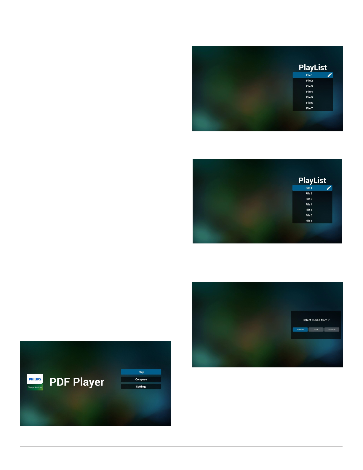
2. Select “Play” on the main page, rst you should select one playlist
to play between FILE 1 and FILE 7.
The pencil icon means that the playlist contains the content.
3. Select “Compose” on the main page, rst you should select one
playlist to edit between FILE 1 and FILE 7.
The pencil icon means that the playlist contains the content.
4. If an empty playlist is selected, the App will guide you through
selecting the media source.
All media les should be stored in /philips/ of root directory. For
example,
pdfs : {root dir of storage}/philips/pdf/
4.6.2. PDF Player introduction:
1. The main page of PDF Player, this page consists of three options:
“Play”, “Compose” and “Settings”.
Play: select a playlist to play.
Compose: edit the playlist.
Settings: congure the properties of PDF Player.
32
Page 44
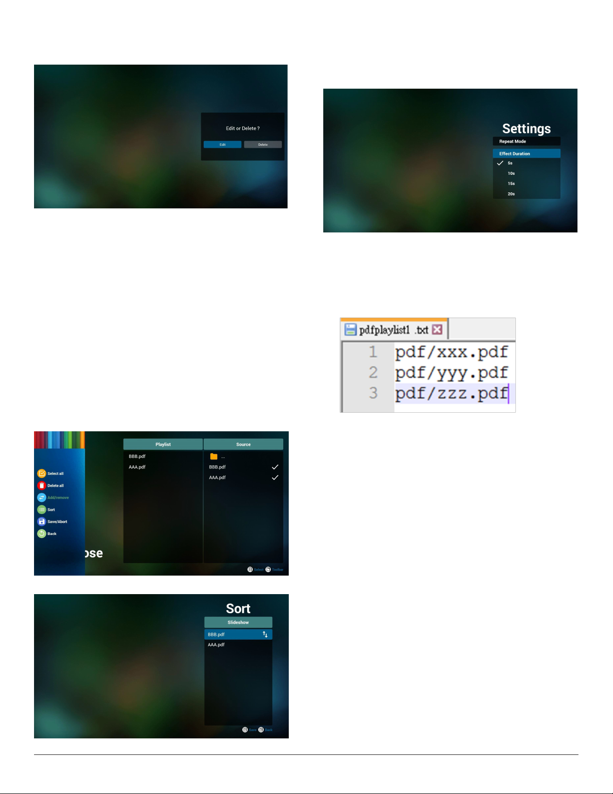
5. To edit or delete a non-empty playlist, select the desired playlist that
has a pencil icon on right side of the le.
6. Once you start to edit a playlist, a menu is displayed as below.
Source- les saved in the memory storage.
Playlist– les saved in the playlist.
The following functions can be operated through the corresponding
keys on the remote control.
Option key – launch the side menu bar
Play key – play the media le.
Info key – show the media info.
Ok key – select/deselect a le.
8. Select “Settings” on the main page, there are two options available:
“Repeat Mode” and “Effect Duration”.
Repeat Mode: set the repeat mode.
Effect Duration: duration of photo effect.
9. How to edit the PDF list via FTP?
Step 1. Create a text le of PDF player.
- File name : pdfplaylistX.txt, “X” means playlist
number(1,2,3,4,5,6,7).
Ex. pdfplaylist1.txt, pdfplaylist2.txt
- Content:
6-1. From the side menu bar, the following functions are available:
- Select all: select all les saved in the storage.
- Delete all: delete all playlist les.
- Add/Remove: add or remove a playlist from source.
- Sort: sort the playlist.
- Save/abort: save or abort the playlist.
- Back: return to the previous menu.
7. If “Sort” is selected, you can customize the le order severally.
Step 2. Copy pdfplaylistX.txt to “philips” folder of the internal
storage. You may use FTP to do this.
- File path : /storage/emulated/legacy/philips (for DL, PL)
Ex. /storage/emulated/legacy/philips/pdfplaylist1.txt
Step 3. Add the PDF les in “PDF” folder which is under “philips”
folder of your internal storage.
- Ex. /storage/emulated/legacy/philips/pdf/xxx.pdf
/storage/emulated/legacy/philips/pdf/yyy.pdf
/storage/emulated/legacy/philips/pdf/zzz.pdf
Step 4. Start the PDF player App, it will import the text le of PDF
player automatically.
Note. Once the playlist le (text) is imported, any changes made
through the remote control will not be recorded in the playlist text
le.
Media Hotkey:
Play: play the le.
Pause: pause.
Fast forward: skip to the next page. If the page is close to the end
of le, it will go to the next le.
Rewind: skip back to the previous page. If the page is close to the
beginning of le, it will go to the last le.
Stop: return to the rst page of le.
33
Page 45
Color Hotkey:
Blue: Zoom in (+10%)
Yellow: Zoom out (-10%)
OK: Restore zoom
Arrow keys:
Up/Down/Left/Right: Adjust the page. (when the page is zoomed
in/out)
Left: Previous page. (when the page is not zoomed in/out)
Right: Next page. (when the page is not zoomed in/out)
Combination key:
Number key + OK key: select a specic page and press OK key to
change the page.
- Press a number key.
- Press OK key, the page number will be shown on the bottom
side of the page. If the page number is greater than the total page
number, it will keep the current page number at the bottom side of
the page.
4.7. CMND & Play
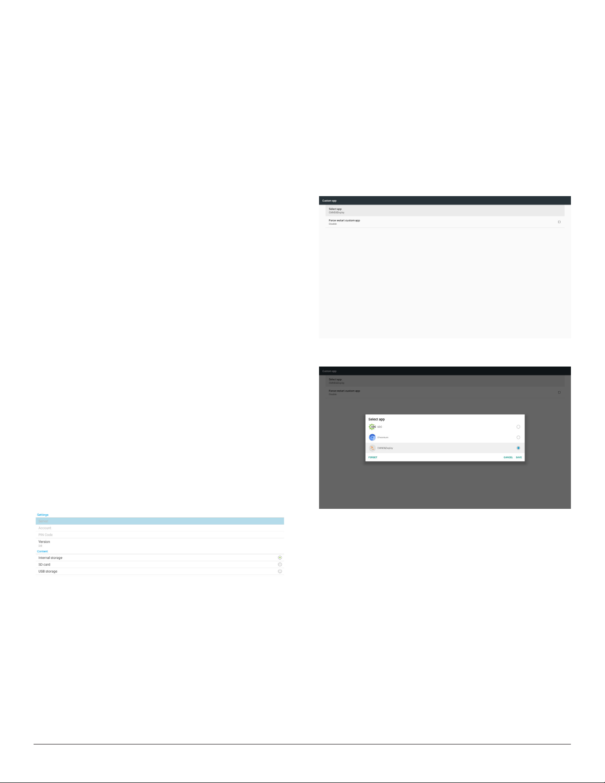
1) Server
Setup CMND & Play server address
2) Account
Setup CMND & Play account
3) PIN Code
Setup CMND & Play PIN code
(4) Version
There are two options, Ver.2 and Ver.3
Ver. 2
use 2.0/2.2 agreement
Ver. 3
use 3.0/3.1 agreement
(5) Content
There are 3 options available: internal storage, SD card and USB
storage.
If Ver.2, is selected, Ser ver/Account/PIN code will be shown in gray
and cannot be set.
4.8. Custom App
Set up the application for Customer Source.
Note:
(1) Only display the App installed by user.
(2) System’s pre-installed App is not displayed.
4.8.1. OSD Menu operation:
RCU: Source > Custom
If a customer APK is set, the PD will open the customer App when
switching the source to Customer mode.
If the customer APK is not set, the PD will show a black screen when
switching the source to Customer mode.
4.8.2. Function Introduction
Save
Pressing Save will perform the function of storage.
Forget
After pressing Forget, those previously stored information can be
removed.
Cancel
Cancel and close the dialog box.
If there is no customer installed APK, the list will be blank.
If the options are not available, “Save” and ”Forget” keys will be shown
in gray.
4.8.3. Force restart custom app:
If the app is closed due to an exception, the app will be automatically
reopened.
34
Page 46
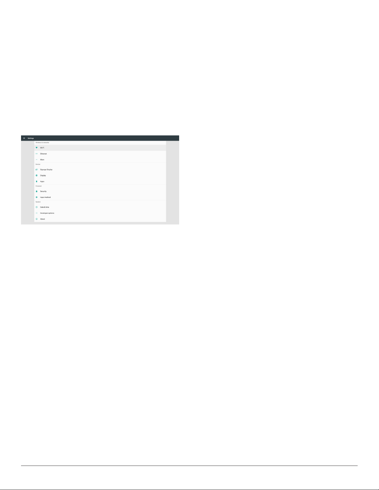
5. Setting
Main items:
(1) Wi-Fi
(2) Ethernet
(3) More (available when 4G module is connected)
(4) Signage Display
(5) Display
(6) Apps
(7) Security
(8) Input method
(9) Date & time
(10) Developer options
(11) About
5.1. Wi-Fi
Go to the wireless network settings. On the available network list,
select an AP (Access Point) on an existing wireless network.
Notes:
1. Ethernet will be disabled automatically if Wi-Fi is connected
to the network correctly.
2. A particular model of Wi-Fi module is required. Please consult
the dealer or service technician for help.
5.2. Ethernet
Go to the Ethernet network settings and make the required settings.
After enabling Ethernet, the following settings will show:
(1) Connection Type (available connection types: DHCP and
Static IP)
A. DHCP
DHCP automatically provides the IP address, Netmask,
DNS Address and Gateway to access the Internet so you
do not have to enter them manually.
If the connection is successful, the current network
conguration will be displayed.
B. Static IP
Enter the IP address, Netmask, DNS address and gateway
manually.
Note:
Input limitation of IP address, netmask, DNS address and
gateway address
(1)Format: number 0-9, decimal point “.”
(2) Mac Address
Note:
Ethernet will be disabled automatically if Wi-Fi is connected to
the network correctly.
5.3. More (available when 4G module is connected)
Control Cellular networks.
Note :
1. Available only when 4G module is connected.
2. The option of “Tethering & portable hotspot” is available only
when Wi-Fi module is detected.
3. Network info will be different due to different carrier.
5.4. Signage Display
(1) General Settings
A. Signage display name
B. Boot Logo
C. Screenshot
D. Navigation bar
(2) Server Settings
A. Email notication
B. FTP
C. Remote control
(3) Source Settings
A. Media player
B. Browser
C. CMND & Play
D. PDF player
E. Custom app
(4) Network application
A. Proxy
B. SICP network port
(5) System tools
A. Clear Storage
B. Reset
C. Import & Export
D. Clone
E. Security
(6) Misc.
A. Tiling Tool
B. TeamViewer Support
(7) System updates
A. Local update
(8) Scaler FW updates
A. Start update
5.4.1. General Settings
1. Signage Display Name
Set PD name “PD_” + Ethernet Mac Address.
Note:
Input limitation:
(1) length: maximum 36 characters
(2) format: no limitation
35
Page 47
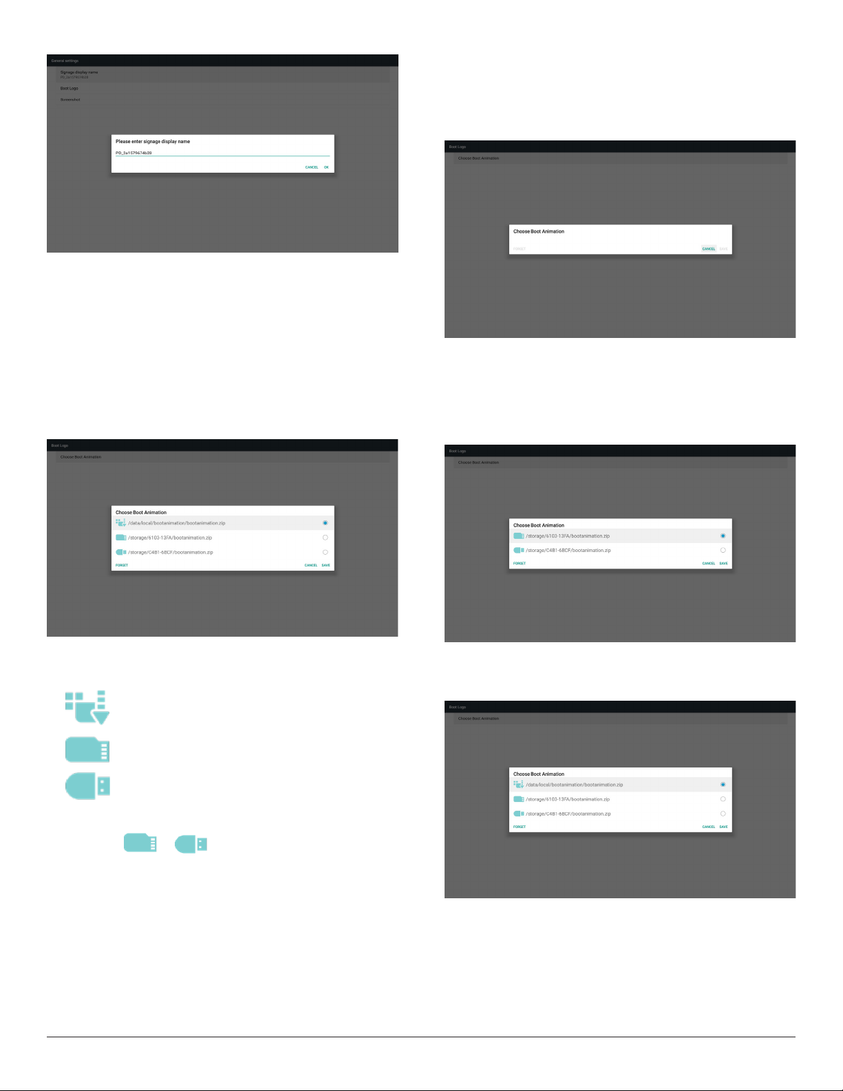
2. Boot Logo
1) Scalar OSD menu to control Android boot logo
Scalar OSD menu operation
RCU: Home > Conguration2 > Logo > On/Off/User
Under user mode, select your own animation le of boot logo le.
Note:
(1) File name of boot animation: bootanimation.zip
(2) USB and SD card will be selectable. No priority issue.
2) When boot logo is selected, the system will check if
bootanimation.zip is present in the USB and SD card.
Scenario introduction:
Case 1
When the system cannot nd bootanimation.zip le under SD
and USB, the le list will be empty. The “Save” and “Forget” options
become gray.
Case 2
The customized bootanimzation.zip le can be stored in the SD
and USB memory. The default priority is the SD card, meaning
that the system selects the le in the SD card automatically. If the
bootanimzation.zip is stored only in the USB drive, then the system
will select the le in the USB drive (as the SD card has no le).
Function introduction:
a. Option description
Use customized boot animation le which is
copied from SD card or USB
Use boot animations le under SD card
Use boot animations le under USB
b. Save
If you select or , press Save key to save bootanimzation.
zip from the SD card or USB to /data/local and set it as boot logo.
c. Forget
Press Forget key to delete /data/local bootanimation.zip and conceal
the boot logo.
d. Cancel
Cancel and close the dialogue box.
Case 3
When a customized boot logo is selected, the screen will show /
data/local/bootanimation.zip.
36
Page 48
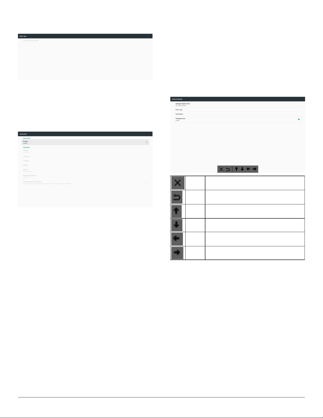
3) If the logo item of OSD menu is On or Off, then the boot
animation in Android settings is not selectable.
3. Screenshot
After enabling the screenshot feature, screenshot time slot and its saving
path can be set.
Notes:
Time slot for deleting and taking the screenshot:
(1) delete the picture at initial time which is 0 sec.
(2) take the screenshot at the rst 40 sec.
Set the interval time for deleting the screenshot images. The available
options are “One day” and “One week”.
7) Send screenshots via email
Send the screenshot images as an e-mail attachment to the
administrator.
Please refer to Email notication.
Note:
Ensure that Email setting is done, so that the screenshot can be sent
immediately.
4. Navigation bar
Set up to show or hide the navigation bar during the touch operation.
1) Interval
Set interval time frame: 30 mins or 60 mins.
2) Start Time
Set the time to start taking the screenshot.
Note:
(1) If the start time is not set, the screen will show current time
automatically
(2) The start time cannot be later than the end time, otherwise it will
show an error message.
3) End Time
Set the end time to stop taking the screenshot.
Note:
(1) If the end time is not set, the screen will show current time
automatically
(2) The start time cannot be later than the end time, otherwise it will
show an error message.
4) Repeat
Set the repeat mode for screenshot by setting the time frame.
(multiple selection)
5)Save to
Set the storage where the screenshot will be saved. The default
storage is your internal storage.
Note:
The system creates a folder philips/Screenshot/ automatically in the
root of your internal storage. The picture will be saved to philips/
Screenshot/.
6) Purge Screenshots
Cancel Cancel the navigation bar.
Back Back to the previous action.
Top Move the navigation bar to Top.
Bottom Move the navigation bar to Bottom.
Left Move the navigation bar to Left.
Right Move the navigation bar to Right.
37
Page 49
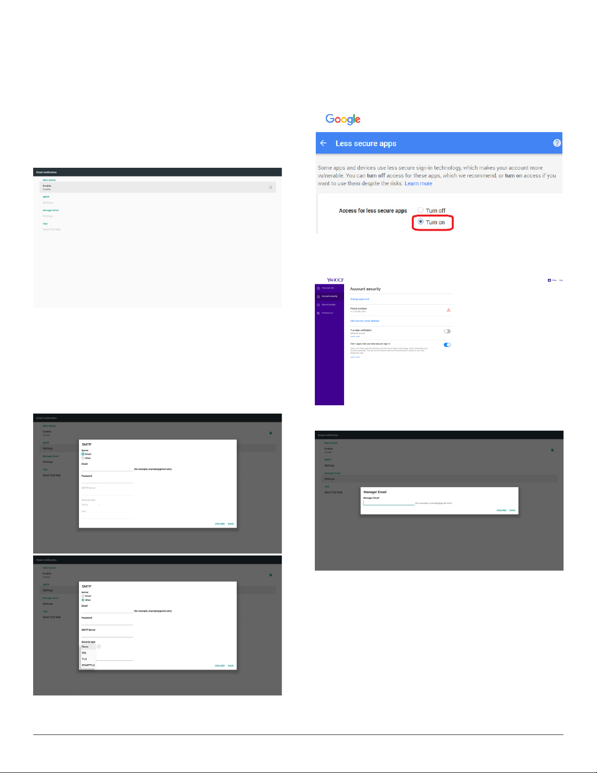
5.4.2. Server Settings
1. E-mail Notication
Enable/disable the E-mail notication feature. Set E-mail notication
conguration after enabling this feature.
Note: the following events are automatically sent to manager by E-mail:
(1) Critical: warning message of Android system
(2) Mediaplayer: playlist is empty, or media le is not supported…
(3) Browser: playlist is empty.
(4) CMND & Play: no content
(5) Pdfplayer: playlist is empty
(6) FTP: someone logs in to PD
1) SMTP
Set SMTP conguration.
Select Gmail account or other mail account and set the SMTP
server, security type and port item.
Note
Password input limitation
(1) Length: 6-20 characters
(2) Format: no limitation
Gmail safety setting
If a problem occurs when sending the e-mail via Gmail, please visit
Google website:
https://www.google.com/settings/security/lesssecureapps
for checking the security setting of your Google Account. Then turn
on “Access for less secure apps”.
Yahoo Email Security Setting
If a problem occurs when sending the e-mail via Yahoo Email, enable
the option of “Allow apps that use less secure sign in”.
2) Manager Email
Specify the destination address to receive the e-mail.
38
3)Test
Send a Test Mail
To check if your Gmail account can receive/send e-mail.
Note
When Email is disabled, “Send Test Mail Button” button will gray out.
Page 50
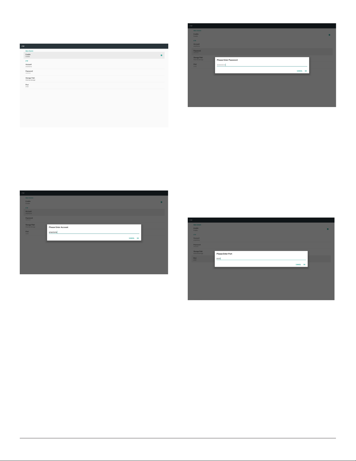
2. FTP
Click the checkbox to enable/disable the FTP server feature. After
enabling this feature, les can be shared on the FTP.
1) Account
Set FTP account
Note:
Input limitation
(1) Length: 4-20 characters
(2) Format:
I. English letter: a-z and A-Z
II. Number 0-9
3) Storage Path
Show default path: Internal storage.
Note:
Display the path of internal storage which is unchangeable.
4) Port
Set FTP port number.
Note:
Input limitation:
(1) Length: Max 5 characters
(2) Range: 1025 ~ 65535
(3) Format: Number 0-9
(4) Default: 2121
(5) Unavailable port: 9988, 15220, 28123, 28124 and SICP network
port.
2) Password
Set the password for FTP.
Note:
Input limitation
(1) Length: 6-20 characters
(2) Format:
I. English letter: a-z and A-Z
II. Number 0-9
FTP password display
(1) The password are hidden under asterisks if the password is set using
the remote control.
(2) After setting, the password are hidden under asterisks.
3. Remote Control
Enable or disable the remote control.
Input the server address. If the server is not registered, you will be asked
to enter the PIN code.
Bind status:
(1) If the device does not have appropriate network connection, a
message “Network is disconnected” will appear.
(2) If the device is equipped with network function, but is not
connected to the remote control server, a message “Server is
disconnected” will appear.
(3) Show “Server is unbinded” if the remote control server replies its
unbound status.
(4) Show “Server is binded” if the device is bound with Sever
successfully.
(5) Show Error PIN code if the PIN code is not correct.
39
Page 51
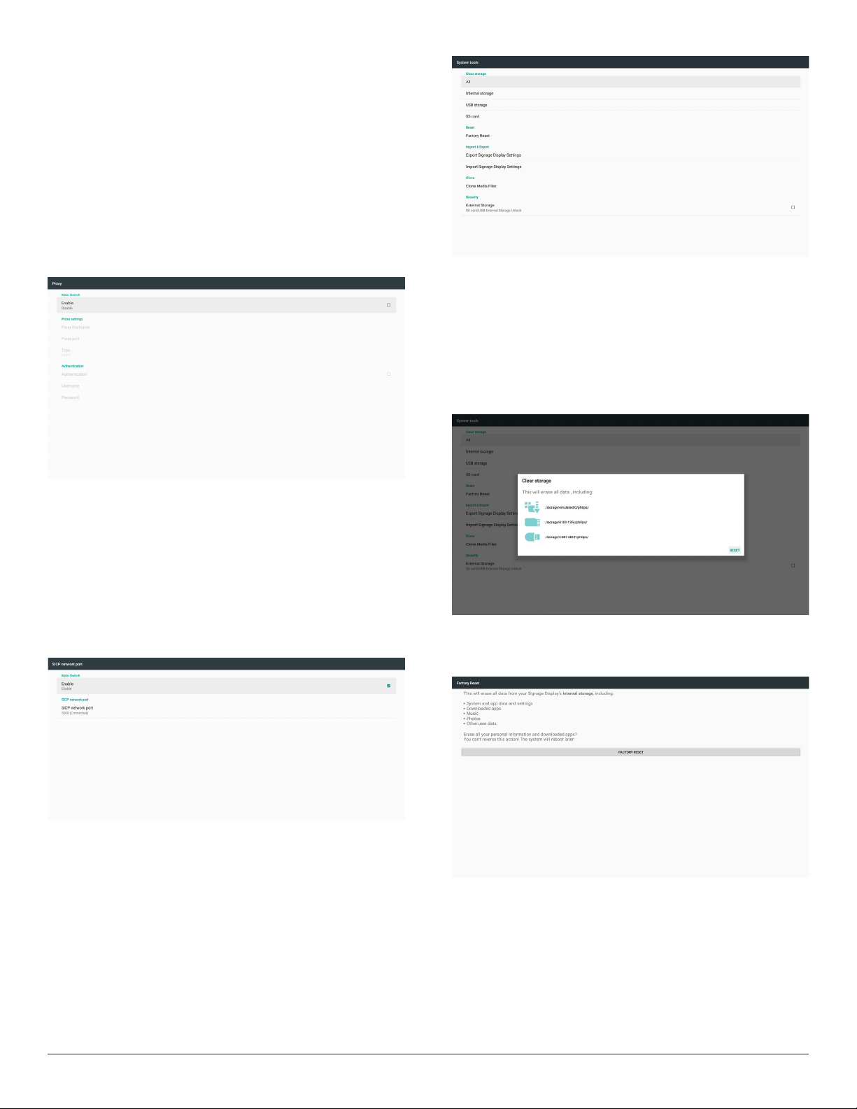
5.4.3. Source Settings
1. Media Player (Please refer to the instructions of 4.4. Media Player)
2. Browser (Please refer to the instructions of 4.5. Browser)
3. CMND & Play (Please refer to the instructions of 4.7. CMND &
Play)
4. PDF Player (Please refer to the instructions of 4.6. PDF Player)
5. Custom App (Please refer to the instructions of 4.8. Custom App)
5.4.4. Network application
1. Proxy
Enter the Host and Port of the proxy server.
5.4.5.1 Clear Storage
The purpose is to clear data in the folder “Philips”. It is divided into 4
modes:
(1) Clear all Philips folders.
(2) Clear the folder “Philips” from the internal storage only.
(3) Clear the folder “Philips” from the USB storage only.
(4) Clear the folder “Philips” from the SD card only.
A dialog box lists all folders that the system is going to clear.
2. SICP network port
Change SICP Network Port.
Note:
Input limitation
(1) Length: Max 5 characters
(2) Range: 1025 ~ 65535
(3) Format: Number 0-9
(4) Default: 5000
(5) Unavailable port: 9988, 15220, 28123, and 28124.
5.4.5. System Tools
System tools consist of 5 main functions:
(1) Clear Storage
(2) Factory Reset
(3) Import & Export
(4) Clone Media Files
(5) External Storage
5.4.5.2 Factory Reset
This function allows you to clear all user settings and recover to factory
default values.
40
Page 52
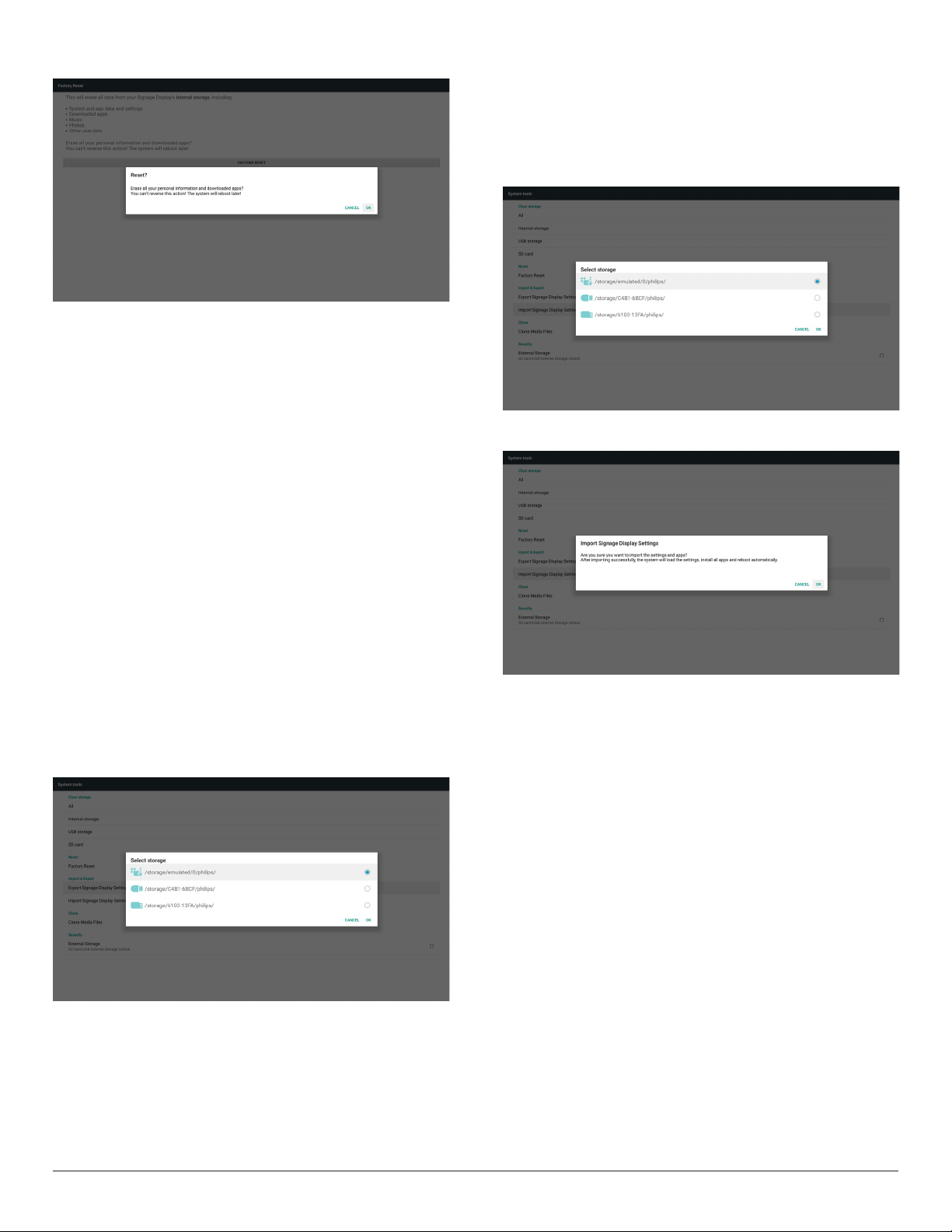
Press OK to execute Reset function automatically
.
5.4.5.3 Import & Export
This function allows you to import/export the settings and 3rd party
APK from/to other device.
Notes.
(1) Saved le name:
A. Settings_global.xml
B. Settings_secure.xml
C. Settings_system.xml
D. Signage_settings.db
E. AndroidPDMediaPlayerData.db
F. AndroidPDPdfData.db
G. AndroidPDUrlListData.db
H. Smartcms.db
(2) The les will be expor ted to philips/sys_backup folder of the
selected storage.
Export Signage Display Settings
Database will be exported to the folder “Philips” of your USB or SD
card.
(1) Export database
(2) Export 3rd party APK to Philips/app/
Note:
If the selected storage (USB storage or SD card) does not contain the
folder “Philips”, then the system will create it automatically.
A list of all available storage (internal storage/SD card/USB storage):
Import Signage Display Settings
Data can be imported from the folder “Philips” of the selected storage
(USB storage or SD card).
(1) Import the settings and apps
(2) Auto install 3rd party APK from Philips/app/
A list of all available storage (internal storage/SD card/USB)
A conrmation dialog box is displayed before importing the settings and
apps.
41
Page 53
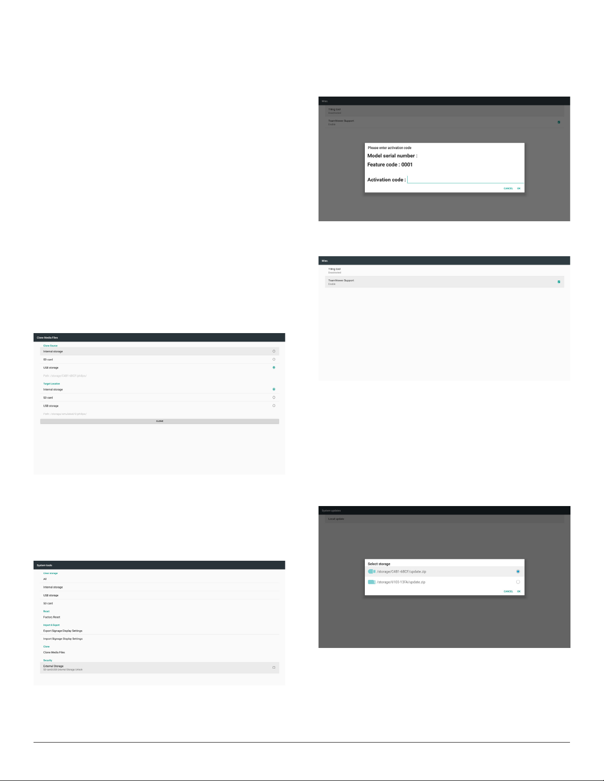
5.4.5.4 Clone Media File
This function allows you to copy the media les from the folder “Philips”
of your source storage (internal, SD card or USB).
1. The following folders will be copied (under the folder Philips)
(1) philips/photo
(2) philips/music
(3) philips/video
(4) philips/cms
(5) philips/pdf
(6) philips/browser
2. File extension of cloned le is “.cms”)
Source storage
(1) Internal storage
(a) check FTP
(b) check /Philips/ folder
(2) SD/USB
Files under root
Target Location
(1) Internal storage
Save to /Philips/
(2) SD/USB
Save to root
5.4.6. Misc.
5.4.6.1 Tiling tool
To activate the tiling tool function, enter the serial number provided by
your dealer.
5.4.6.2 TeamViewer Support
Enable/Disable the TeamViewer support.
5.4.5.5 External Storage
Enable: lock the SD card/USB External Storage.
Disable: unlock the SD card/USB External Storage.
Note:
Insert the SD card/USB External Storage back to the device after
unlocking the external storage.
5.4.7. System update
1. Local update
The system will auto search “update.zip” from the internal storage, USB
disk or SD card. If it is found, it will be shown on the list.
Note:
a. It only supports Android full image.
b. The le name should be “update.zip”
c. The le should be stored in the root folder of your storage.
42
Page 54
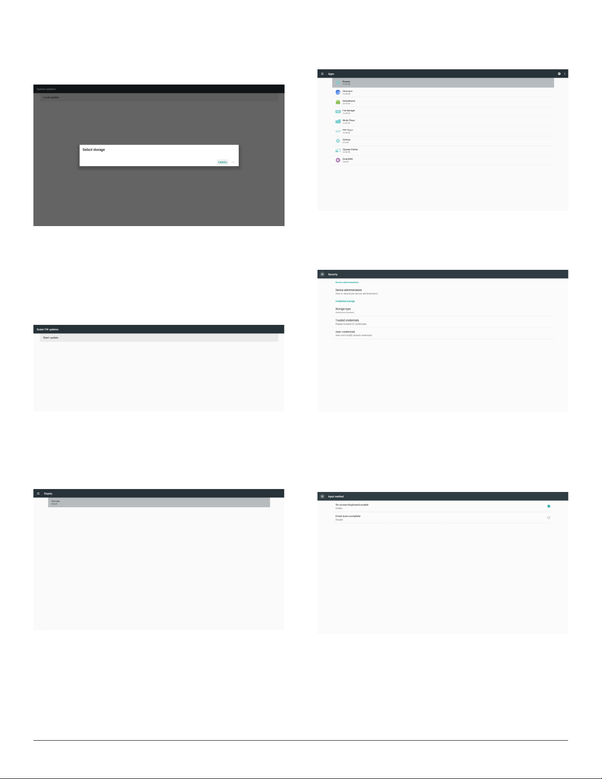
(2) After selecting the le “update.zip”, the system will restart and star t
updating.
(3) If “update.zip” is not found, the message “no content” appears. (OK
button will be shown in gray)
5.4.8. Scalar FW update
1. Start updating
It automatically searches the le “scaler.bin” in internal storage.
Notes
(1) File name should be scaler.bin
(2) The le should be stored in {Internal}/philips/scaler/
5.6. Apps
Display application information.
5.7. Security
(1) Device administration: View or deactivate device administrators.
(2) Credential storage: Display trusted CA certicates.
Note: If a black screen appears during updating process, please manually
remove the AC power and plug it in again to complete the
updating process.
5.5. Display
Set the font size of display from Small/Default/Large/Largest.
5.8. Input method
(1) On-screen keyboard enable: Show or hide the software keyboard
on screen.
(2) Email auto-complete: Autocomplete for email addresses in
android.
43
Page 55
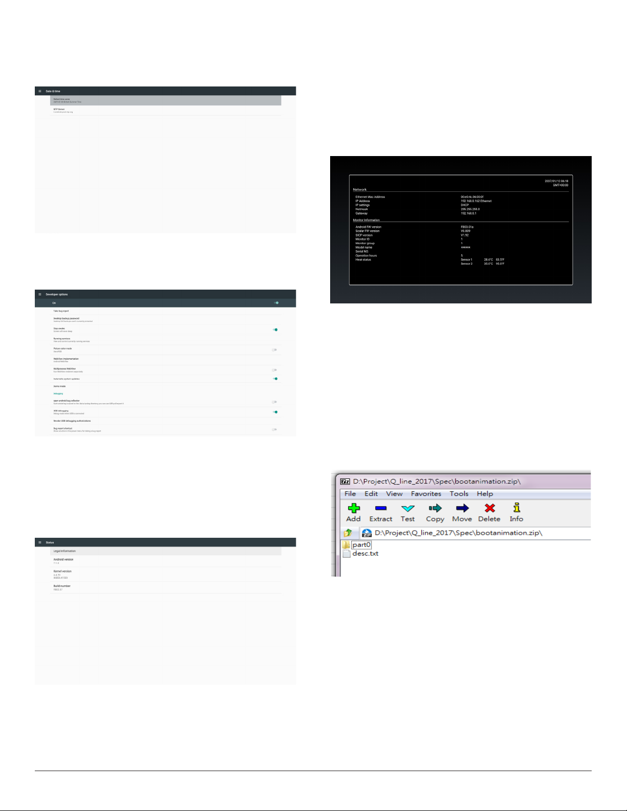
5.9. Date & time
Allow users to change time zone settings.
Tap “NTP Server” to set the custom NTP server address.
5.10. Developer options
Android developer options. For more information please visit
https://developer.android.com/index.html
5.11. About
View the following information of the system:
(1) Legal Information: show the open source licenses.
(2) Android version
(3) Kernel version
(4) Build number
5.12. Supplementary
5.12.1. Quick Info
Press “Info + 77” to startup quick info.
Quick info will show “Network” and “Monitor Information”.
Note:
Operation hours: updates every minute.
Heat status : updates every 5 seconds.
5.12.2. How to custom an Android boot
animation?
1. Overview
The Android boot animation is a script used to load PNG les when
the device boots. It is included in an uncompressed zip le called
bootanimation.zip.
2. In the bootanimation.zip le
The bootanimation.zip as follow:
• The image folder (contains PNG images named in incremental
numbers)
• The desc.txt le
44
(1) The image folder
This folder contains PNG images which are named by numbers,
starting from something like 0000.png or 0001.png and proceeding
with increments of 1. The minimum number of folder is 1 and the
maximum number of folder is unlimited.
(2) The desc.txt le
This le denes how the images in the folder(s) are displayed during
the boot animation, in the following format:
- Width Height Frame-rate
- mode Loop delay-time Folder1
- mode Loop delay-time Folder2
An example of a desc.txt le is:
- 1920 1080 30
Page 56
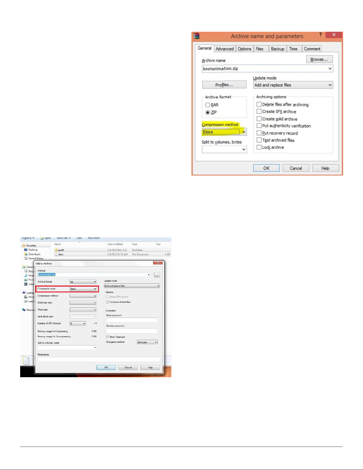
- p 1 0 part0
- p 0 0 part1
a. The rst line
1920 and 1080 dene the width and height of the screen
resolution.
30 is the frame rate in fps (frames per second) i.e. number of
images to display per second.
b. The second and third lines have a same format.
The rst “p” means that the play mode stops immediately when
the boot process is complete.
The number next to ‘p’ denes the repeat mode
- Set to 0 to make the part loop indenitely until the device
boot is complete.
- Set to 1 to make the part playback for once.
The next number denes the delay time(ms). For example, if it is
set to 10, the system will be delayed for 10ms when all image les
nished playing.
Part0 and part1 refer to image folder names.
As to the above example, the boot animation will play at a resolution of
1920 by 1080 pixels, at a frame rate of 30 fps, starting with the contents
of part0 folder. After playing them in one loop, switch to the contents of
part1 folder and play them continuously until the device boot process is
complete.
3. Zip le:
Select all (including image folders and desc.txt) inside the Bootanimation
folder and zip them into a new uncompressed zip archive using your
favorite compression utility such as 7zip or WinRAR and so on.
If using 7zip, set compression level to “Store”.
If using WinRAR, set “Compression method” to “Store”.
or bootanimation WON’T work
4. Apply the custom bootanimation
Procedure:
(1) Place your custom bootanimztion.zip le into the external SD
card or USB and plug the storage device into Phillips PD platform.
(2) Make sure that the Logo option is enabled.
Press the Home key on RCU: OSD menu > Conguration 2 >
Logo > set “User”
(3) Press the combination key “Home + 1888” on RCU to go to
Admin mode:
Settings > Signage Display > GENERAL SETTINGS > Boot Logo
(4) The system will search the bootanimation.zip on the external SD
card or USB automatically and copy it to /data/local
(5) Once the step 1~4 are complete, restart the system. The new
customized boot animation should be displayed during boot time.
5.12.3. How to Install Android app?
There are 3 ways to install your own Android App.
(a) Via File Manager in Admin Mode
1. If you have apk already
1.1 Copy your APK to the USB disk or SD card, and plug the
storage device into Philips Android Signage Display.
1.2 Go to Admin Mode > Apps > File Manager
1.3 Use File Manager to nd your APK to be installed. Simply press
“OK” on the selected APK.
2. Download an APK using the Chromium browser, then go to
<internal storage path>/Download/ by File Manager.
2.1 The next steps are the same as described above. Please note,
each model may have different <internal storage path>.
45
Page 57
(b) Via Adb Shell
1. Make sure that your PC can connect to Philips Android Signage
Display using adb.
2. Prepare your apk in a folder(for example, C:\apkfolder) on your
PC.
3. Execute the following instruction using command line tool.
C:\apkfolder> adb install -r apk_name.apk
(c) Via Customized Intent
1. If you develop an apk which can download any Android App, then
your APK can issue a customized intent.
2. Giving that the apk name and the path have been stored., the
system will help you to install by program.
Description Intent Parameters
The absolute le path
including the le name.
lePath
keep
php.intent.
Sw Update
For example,
Intent intent = new Intent();
intent.setAction(“php.intent.action.UPDATE_APK”);
intent.putExtra(“lePath”, “/sdcard/Download/sample.apk”);
intent.putExtra(“keep”, true);
intent.putExtra(“packageName”, “com.tpv.example”);
intent.putExtra(“activityName”, “com.tpv.example.MainActivity”);
intent.putExtra(“isAllowDowngrade”, true); // allow downgrade
sendBroadcast(intent);
action.
UPDATE_
APK
packageName
activityName
isAllowDowngrade
Please make sure that
the le access permission
should be 664 at least.
Indicate that you want
to keep the le or not
after updating. The default
value is false.
The target package
you want to launch
automatically after
updating.
The target activity
you want to launch
automatically after
updating. But if current
top activity is not
activityName, nothing
happened.
"true: update apk no
matter the version of
target apk is lower than
the verion of current one
or not.
false: stop install if it is
downgrade."
46
Page 58
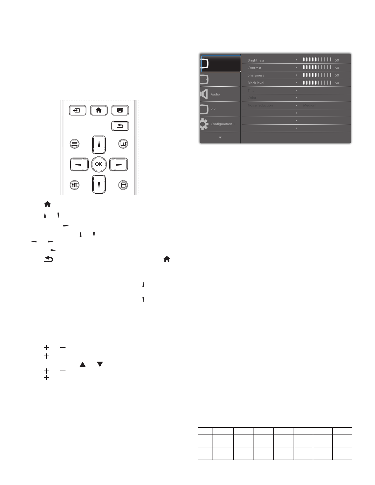
6. OSD Menu
Audio
PIP
Conguration 1
Contrast
Sharpness
Color
Tint
Brightness
Black level
Noise reduction
50
50
50
50
Medium
An overall view of the On-Screen Display (OSD) structure is shown
below. You can use it as a reference for further adjustment of your
display.
6.2. OSD Menu Overview
6.2.1. Picture menu
6.1. Navigating the OSD Menu
6.1.1. Navigating the OSD menu using the
remote control
SOURCE
1. Press [ ] button on the remote control to display the OSD menu.
2. Press [ ] or [ ] button to choose the item you want to adjust.
3. Press [OK] or [ ] button to enter the submenu.
4. In the submenu, press [ ] or [ ] button to toggle among items, press
[ ] or [ ] button to adjust settings. If there is a submenu, press
[OK] or [ ] button to enter the submenu.
5. Press [ ] button to return to the previous menu, or press [ ]
button to exit the OSD menu.
NOTES:
• When there is no OSD menu on the screen, press [ ] to display the
menu of {Smart picture}.
• When there is no OSD menu on the screen, press [ ] to display the
menu of {Audio source}.
6.1.2. Navigating the OSD menu using the
display’s control buttons
1. Press [MENU] button to display the OSD menu.
2. Press [ ] or [ ] button to choose the item you want to adjust.
3. Press [ ] button to enter the submenu.
4. In the submenu, press [ ] or [ ] button to toggle among items,
press [ ] or [ ] button to adjust settings. If there is a submenu,
press [ ] button to enter the submenu.
5. Press [MENU] button to return to the previous menu, or press
[MENU] button several times to exit the OSD menu.
FORMAT
INFOLIST
OPTIONSADJUST
Picture
Screen
P
Gamma selection
Color temperature
Color control
Native
Native
Brightness(Picture)
Adjust the overall image and background screen brightness(backlight).
Contrast
Adjust the image contrast ratio for the input signal.
Sharpness
This function is digitally capable to keep crisp image at any timings.
It is adjustable to get a distinct image or a soft one as you prefer and set
independently for each
picture mode.
Black level
Adjust the image brightness for the background.
NOTE: sRGB picture mode is standard and cannot be changed.
Tint(Hue)
Adjust the tint of the screen.
Press + button the esh tone color becomes greenish.
Press - button the esh tone color becomes purplish.
NOTE: VIDEO mode only.
Color(Saturation)
Adjust the color of the screen.
Press + button to increase color depth.
Press - button to decrease color depth.
NOTE: VIDEO mode only
Noise Reduction
Adjust the noise reduction level.
Gamma selection
Select a display gamma, It’s refer to the brightness performance curve of
signal input.Choose from {Native} / {2.2} / {2.4} / {s gamma} / {D-image}.
NOTE: sRGB picture mode is standard and cannot be changed.
Color temperature
Select a color temperature for the image. A lower color temperature
will have a reddish tint, while a higher color temperature gives off a
more bluish tint.
10000º K 9300 º K 7500 º K 6500 º K 5000 º K 4000 º K 3000 º K
CCT
0.279 ±
X
0.292 ±
Y
0.030
0.030
0.283 ±
0.030
0.298 ±
0.030
0.299 ±
0.030
0.315 ±
0.030
0.313 ±
0.030
0.329 ±
0.030
0.346±
0.030
0.359±
0.030
0.382±
0.030
0.384±
0.030
0.440±
0.030
0.403±
0.030
47
Page 59
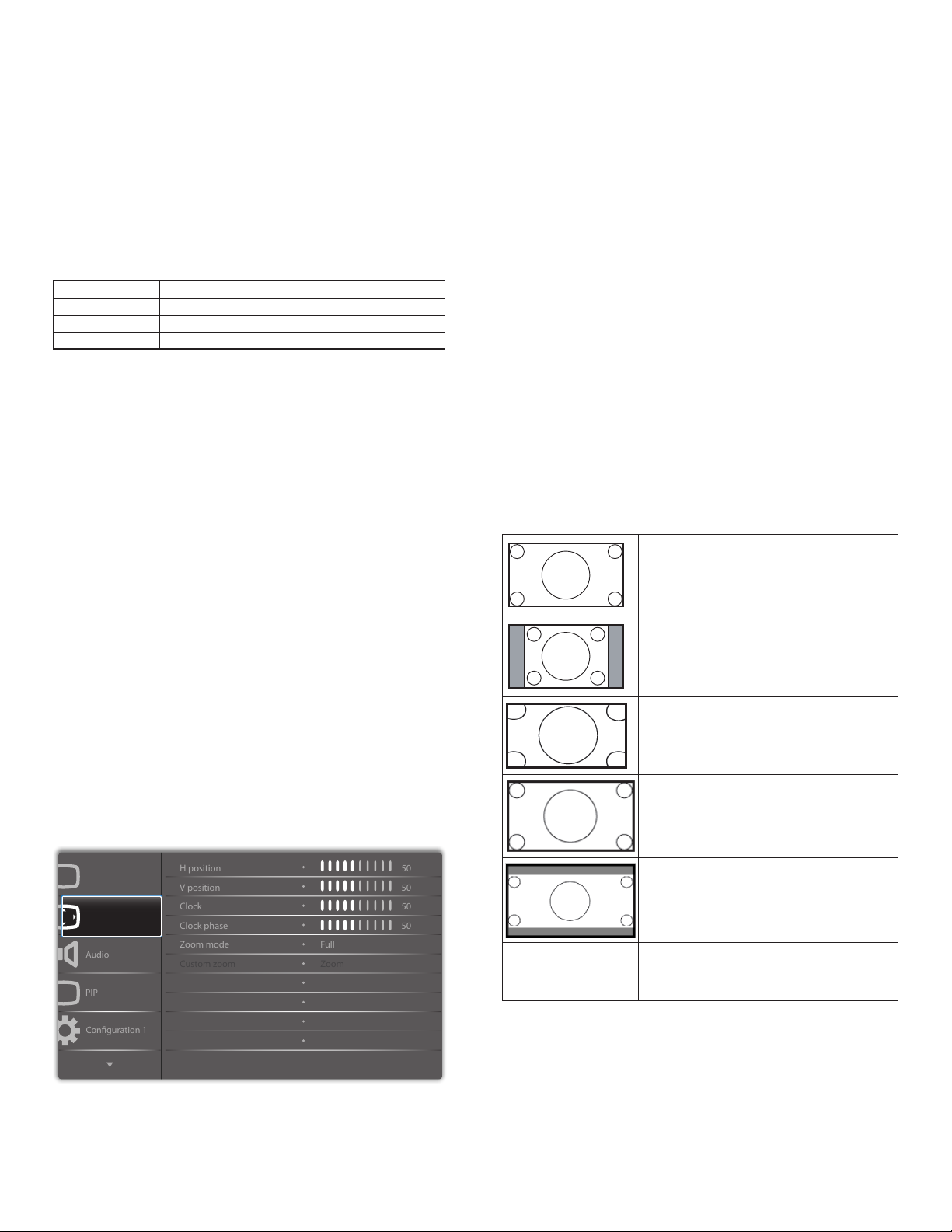
Color control
Audio
PIP
Conguration 1
V position
Clock
Zoom mode
Custom zoom
H position
Clock phase
50
50
50
50
Zoom
Full
The color levels of red, green, and blue are adjusted by the color bars.
R: Red gain, G: Green gain, B: Blue gain.
Smart picture
PQ setting
PC mode: {Standard} / {Highbright} / {sRGB}.
Video mode: {Standard} / {Highbright} / {Cinema}.
Smart Contrast
Auto detect black data and white data on content and set suitable
backlight.
Surface Ratio Backlight Setting
5%-90% (MaxBacklight-MinBacklight)* Surface Ratio/100
<5% Min Backlight
>90% Max Backlight
Smart power
Smart Power control is not relative to brightness control:
1. Initial setting Brigthness
70 (in the range from 0-100)
Power consumption 70% of maximum power consumption
2. Smart Power
OFF: no adaptation
MEDIUM: 80% of power consumption relative to current settings
HIGH: 65% of power consumption relative to current settings
3. Panel saving/Brightness ON: 40% of maximum power consumption
The controls settings should only be visible on its own controls. It
should not have secondary effects on other controls (brightness
setting changes when smart power setting has changed).
Overscan
Change the display area of the image.
ON: Set to display area about 95%.
OFF: Set to display area about 100%.
Picture reset
Reset all settings in the Picture menu.
Select “Yes” and press “SET” button to restore to factory preset data.
Press “EXIT” button to cancel and then return to the previous menu.
6.2.2. Screen menu
H position
Control Horizontal Image position within the display area of the LCD.
Press + button to move screen to the right.
Press - button to move screen to the left.
V position
Control Vertical Image position within the display area of the LCD.
Press + button to move screen upward.
Press - button to move screen downward.
Clock
Press + button to expand the width of image on the screen to the right.
Press - button to narrow the width of image on the screen to the left.
NOTE: VGA input only.
Clock phase
Improves focus, clarity and image stability by increasing or decreasing this
setting.
NOTE: VGA input only
Zoom mode
PC mode: {Full} / {4:3} / {1:1} / {16:9}/ {21:9}/ {Custom}.
Video mode: {Full} / {4:3} / {1:1} / {16:9}/ {21:9}/ {Custom}.
*Zoom mode setting is dened by input. If input in multi-windows, the
setting will apply for windows with the same input.
The INFO OSD will show the latest setting.
Full
This mode restores the correct proportions
of pictures transmitted in 16:9 using the full
screen display.
4:3
The picture is reproduced in 4:3 format and
a black band is displayed on either side of the
picture..
1:1
This mode displays the image pixel-by-pixel
on screen without scaling the original image
size.
16:9
The picture is reproduced in 16:9 format and
a black band at the top and bottom.
Picture
Screen
21:9
The picture is reproduced in 21:9 format and
a black band at the top and bottom.
Custom
P
Auto adjust
Screen reset
Action
Action
Custom zoom
You can use this function to fur ther customize the zoom settings to suit
the image you want to display.
NOTE: This item is functional only when the {Zoom mode} is set to
{Custom}.
Choose to apply the custom zoom settings in
the Custom Zoom submenu.
48
Page 60
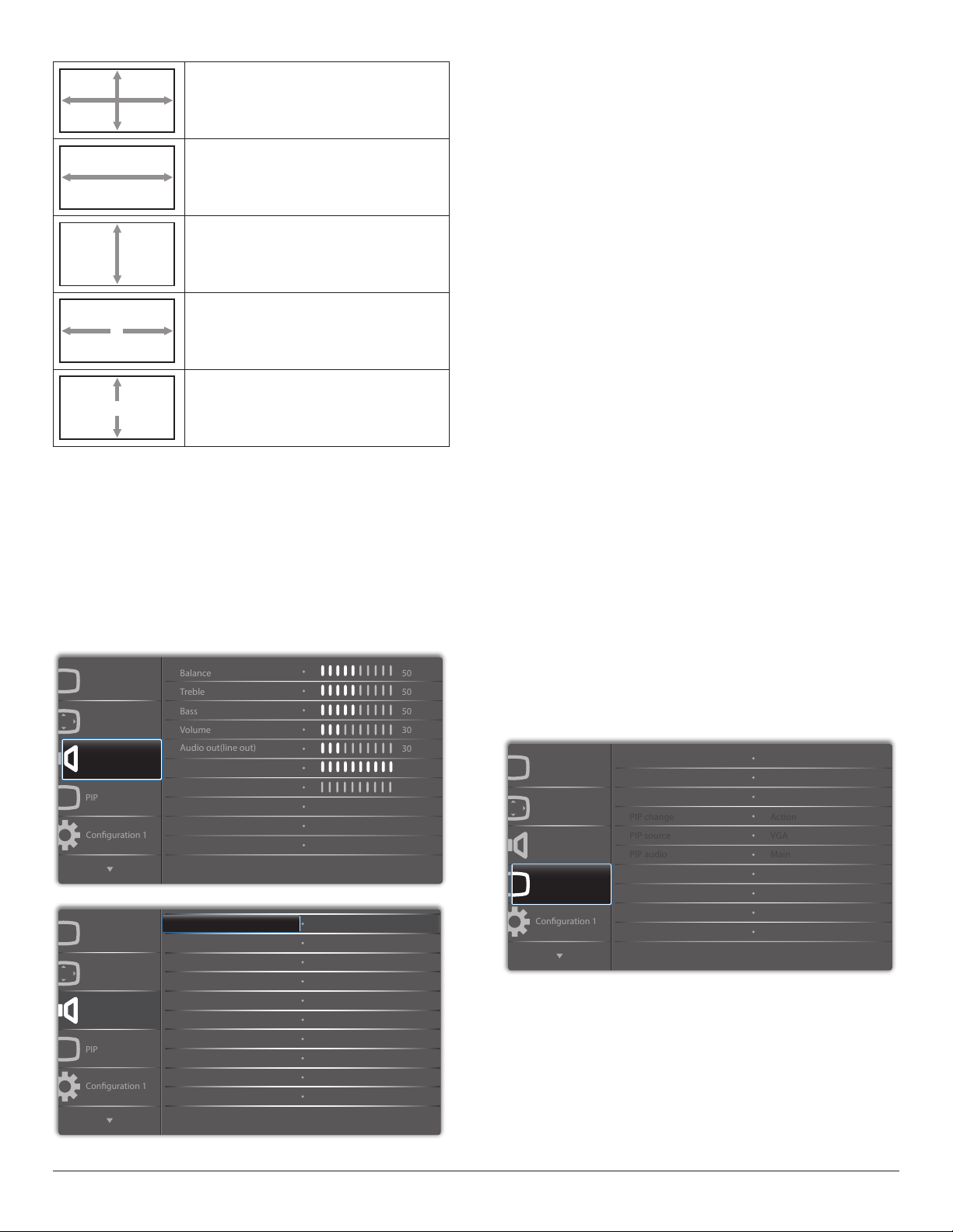
Zoom
PIP
Conguration 1
Treble
Bass
Balance
Volume
Audio out(line out)
50
50
50
30
30
PIP
Conguration 1
Conguration 1
PIP change
PIP source
PIP audio
Action
VGA
Main
Expands the horizontal and vertical sizes of the
image simultaneously.
H zoom
Expands the horizontal size of the image only.
V zoom
Expands the vertical size of the image only.
H position
Moves the horizontal position of the image left
or right.
V position
Moves the vertical position of the image up or
down.
Auto adjust
Press “Set” to detect and adjust H position, V position, Clock, Phase
automatically.
Screen reset
Reset all settings in the Screen menu to factory preset values.
Select “Yes” and press “SET” button to restore the factory preset data.
Press “EXIT” button to cancel and then return to the previous menu.
6.2.3. Audio menu
Picture
Balance
Adjust to emphasize left or right audio output balance.
Treble
Adjust to increase or decrease higher-pitched sounds.
Bass
Adjust to increase or decrease lower-pitched sounds.
Volume
Adjust to increase or decrease the audio output level.
Audio out (line out)
Adjust to increase or decrease line out output level.
Maximum volume
Adjust your own limitation for the maximum volume setting. This stops
the volume from being played too loudly.
Minimum volume
Adjust your own limitation for the minimum volume setting.
Mute
Turn the mute function on/off.
Audio source
Select the audio input source.
Analog: audio from audio input
Digital : audio from HDMI/DVI audio.
Displyport: audio from DP.
Sync. Volume
Enable/disable audio out (line out) volume adjustability to sync with
internal speakers volume, but PD Internal speaker sound will be forced
to be mute.
Audio reset
Reset all settings in the Audio menu to factory preset values.
Screen
Audio
P
Picture
Screen
Audio
P
Maximum volume
Minimum volume
Mute
Audio source
Sync.Volume
Audio reset Action
O
Analog
O
100
0
6.2.4. PIP menu
Picture
Screen
Audio
PIP
PP
Sub mode
PIP size
PIP position
PIP reset
O
Small
Bottom-Right
Action
49
Page 61
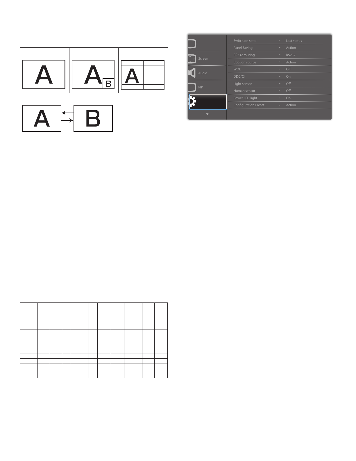
Sub mode
Audio
PIP
Screen
Panel Saving
RS232 routing
WOL
DDC/CI
Switch on state
Boot on source
Light sensor
Power LED light
Conguration1 reset
Human sensor
Action
RS232
Last status
Action
O
On
O
O
Action
On
Select the sub mode.
Choose from: {Off} / {PIP} / {PBP} / {Quick swap} / {Custom}.
Off PIP PBP 2Win
Sub Win1
Input
Quick swap
Switch main on top or
sub on top.
PIP size
Select the size of the sub picture in the PIP (Picture-in-Picture) mode.
Choose from: {Small} / {Medium} / {Large}.
PIP position
Select the position of the sub picture in the PIP (Picture-in-Picture)
mode.
Choose from: {Bottom-Right} / {Bottom -Left} / {Top-Right} / {Top-
Left}.
PIP change
Exchange Main and PIP / PBP / Quick swap input signal.
PIP source
Select the input signal for the sub picture.
PIP audio
Select the audio source in the Sub mode.
• {Main} - Select audio from the main picture
• {Sub} - Select audio from the sub picture.
PIP reset
Reset all settings in the PIP menu to factory preset values.
• The PIP function is available only for certain signal source
combinations as shown in the table below.
HDMI1 HDMI2 DVI DisplayPort VG A
HDMI1 O X X O O X X X X X
HDMI2 X O X O O X X X X X
DVI X X O O O* X X X X X
DisplayPort O O O O O O O O O O
VGA O O O* O O O O O O O
Medoa
Player
Browser X X X O O X O X X X
SmartCMS X X X O O X X O X X
Reader
Custom X X X O O X X X X O
X X X O O O X X X X
PDF
X X X O O X X X O X
Medoa
Player
Browser Smar tCMS
(O: PIP function available, X: PIP function unavailable)
• The availability of the PIP function will also depend on the resolution
of the input signal being used.
PDF
Reader
Custom
6.2.5. Configuration1 menu
Picture
P
Conguration 1
Switch on state
Select the display status used for the next time you connect the power
cord.
• {Power off} - The display will remain off when the power cord is
connected to a wall outlet.
• {Forced on} - The display will turn on when the power cord is
connected to a wall outlet.
• {Last status} - The display will return to the previous power status
(on/off/standby) when removing and replacing the power cord.
Panel saving
Choose to enable the panel saving functions and thus reduce the risk of
“image persistence” or “ghost-imaging”.
• {Brightness} - Select {On} and the image brightness will be reduced
to an appropriate level. The Brightness setting in the Picture menu
will be unavailable when selected.
• {Pixel shift} - Select the time interval ({Auto} / {10 ~ 900} Seconds
/ {Off}) for the display to slightly expand the image size and shift the
position of pixels in four directions (up, down, left, or right).
RS232 routing
Select the network control port.
Choose from: {RS232} / {LAN ->RS232}.
Boot on source
Choose to select source when boot up.
Input: select input source when bootup.
Playlist: select playlist index for Media player, Browser, PDF player.
0: no play list. Same as switch source from OSD.
1~7: playlist number.
WOL
Choose to turn on or off the wake on LAN function.
Choose from : {Off} / { On}
DDC/CI
Choose to turn on or off the DDC/CI communication function.
Select {On} for normal use.
Light sensor(require Philips accessory CRD41 External
Sensor Box)
Choose to turn on or off backlight adjustment according to environment
brightness.
Choose from : {Off} / { On}
50
Page 62
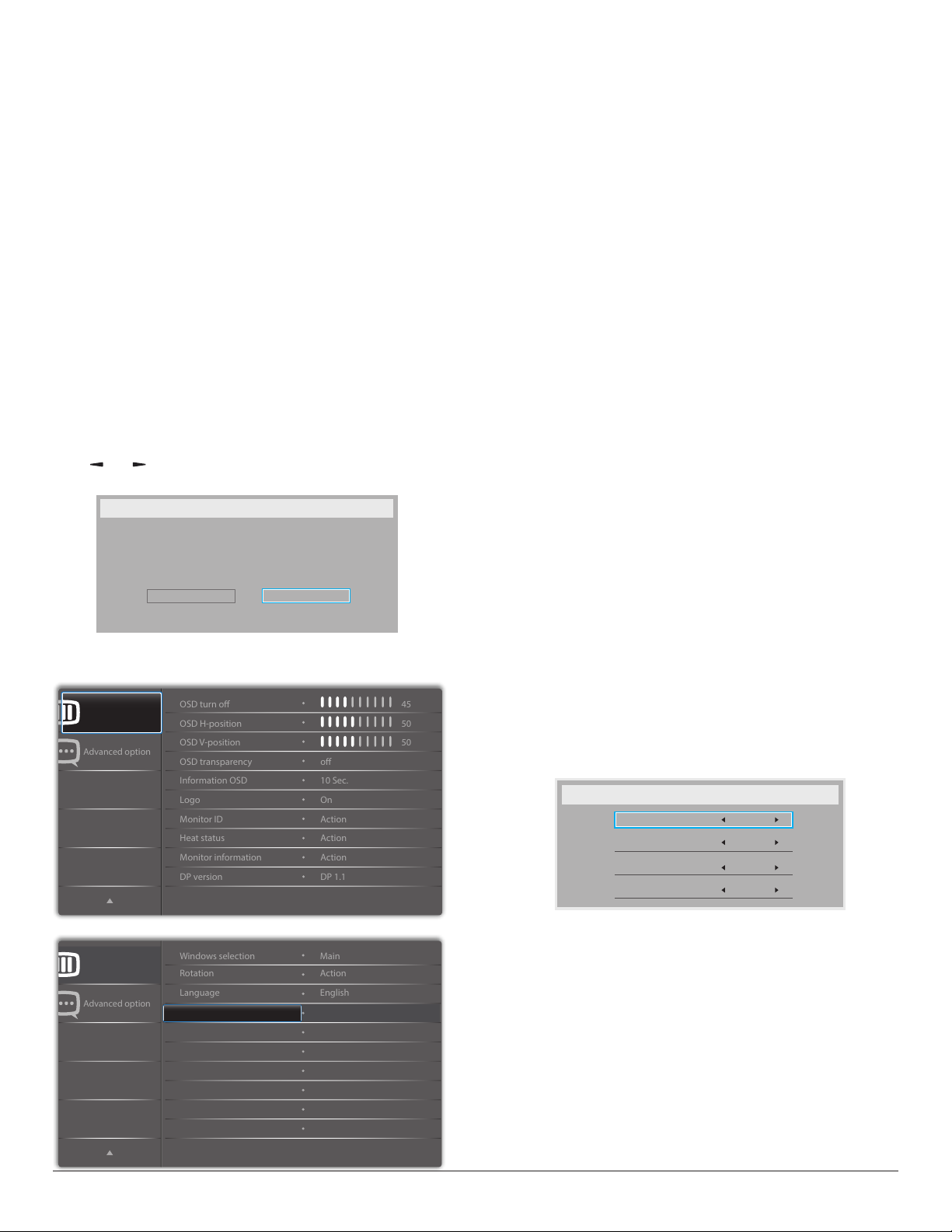
Human sensor(require Philips accessory CRD41 External
Advanced option
OSD H-position
OSD V-position
Information OSD
Logo
OSD turn o
OSD transparency
Monitor ID
Monitor information
DP version
Heat status
50
50
45
o
Action
Action
Action
10 Sec.
On
DP 1.1
Advanced option
Rotation
Language
Windows selection
English
Main
Action
Sensor Box)
The Human sensor can detect if people approach the display or not.
The display will turn off backlight if it detects nothing in setting time.
The display will return to backlight on when people approach the
display..
The options are:
•{Off} (Default), {10 Min.}, {20 Min.}, {30 Min.}, {40 Min.}, {50 Min.}, {60
Min.}
Power LED light
Choose to set power indication LED on or off.
Choose {On} for normal use.
Conguration1 reset
Reset all settings in Conguration1 menu to the factory preset values.
Factory reset
Reset all settings in the OSD menus of {Picture}, {Screen}, {Audio}, {PIP},
{Conguration1}, {Conguration2}, and {Advanced option} to the
factory preset values.
Android settings will also reset when factory reset.
Press [ ] or [ ] button to select {Reset}, and press [OK] button to
do the reset.
Factory reset
Cancel
Reset
6.2.6. Configuration2 menu
Conguration 2
OSD turn off
Set the period of time the OSD (on-screen display) menu stays on the
screen.
The options are: {0 ~ 120} seconds.
*{0} does not disappear automatically.
OSD H-position
Adjust the horizontal position of the OSD menu.
OSD V-position
Adjust the vertical position of the OSD menu.
OSD Transparency
Adjust OSD transparency.
• {Off} - Transparency off.
• {1-100} - Transparency level 1-100.
Information OSD
Set the period of time the information OSD is displayed on the upper
right corner of the screen. The information OSD will display when input
signal is changed.
The information OSD will remain on the screen with {Off} selection.
The options are: {1 ~ 60} seconds.
Logo
Choose to enable or disable the picture of Logo when turn on your
display.
The options are:
• {Off} (Default)
• {On}*
• {User}**
** If Logo set to USER.
User logo does NOT support rotation function.
Monitor ID
Set the ID number for controlling the display via the RS232C
connection. Each display must have a unique ID number when multiple
sets of this display are connected. Monitor ID number range is between
1 to 255.
The option are: {Monitor group} / {Tiling matrix} / {Auto ID}
Conguration 2
Conguration2 reset
Action
• {Monitor group}
The options are: {Off} / {1-254}
• {Off} – {Monitor group} are not supported.
• {1-254} – {Monitor group} are supported. The default setting is
• {Tiling matrix}
Tiling matrix number range is between 1 to 15. 1 is default setting.
The {Auto ID} setup function enables setting up {Monitor ID} of
connected machine according to {Tiling matrix} settings.
Example: Tiling matrix sets as 4
51
1.
Monitor Id
Monitor Id
Monitor group
Tiling matrix
Auto ID
1
1
1
End
Page 63
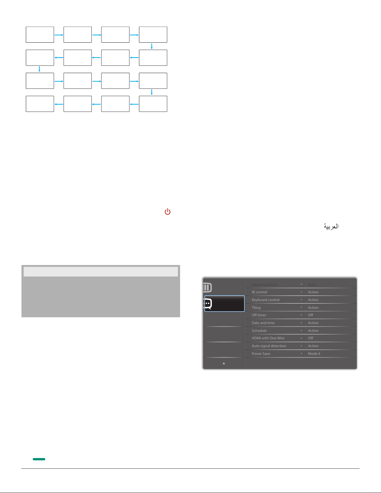
1 2
IR control
Keyboard control
O timer
Date and time
Input resolution
Tiling
Schedule
Auto signal detection
Power Save
HDMI with One Wire
Action
Action
Auto
Action
Action
Action
O
O
Action
Mode 4
5 6
3
4
7 8
9 10 11 12
Rotation
Set the rotation of Main/Sub/OSD
Auto Rotate : Off/On Default : Off
OSD Rotate : Landscape/Portrait Default : Landscape
Image Rotate:
All : Off/On Default : Off
Main : Off/On Default : Off
Sub : Off/On Default : Off
13 14 15 16
• {Auto ID}
The option are: {Start} / {End}. The default is {End}.
• Switch to Start option to set up IDs of machines backward
from current one.
• Once the setup is completed, the option exits to End
automatically.
• To use this function, serial connect all machines with RS-232
cable and set their Control ports to RS-232 too.
Heat status
This function allows you to check the thermal status at any time.
• A temperature-warning message will be shown on the screen if the
temperature reaches 97°C (207°F). All key functions except [ ]
key will then be disabled.
• Once the temperature reaches 98°C (208°F), the display power will
be shut down automatically.
Monitor information
Shows information about your display, including model number, serial
number, operating hours and software version.
Monitor information
Auto Rotate: {Off}, {On} when value is On,automatically detect whether
the PD rotation, Off is set by OSD.
OSD Rotate: {Off}, {On} when value is on, OSD rotate 90 °, Off is
restored.
All: {Off}, {On} when value is on, all Window screen rotate 90 °, Off the
reference set individual window.
Main: {Off}, {On} when value is onn, Main window screen rotate 90 °,
Off is restored.
Sub: {Off}, {On} when value is on, Sub1 Window screen rotate 90 °, Off
is restored.
* When the Main / Sub source is the same, rotation is given priority to
with Sub.
* Not suupored De-Interlacing function in rotation mode.
Language
Select the language used in the OSD menu.
The options are: English/Deutsch/
Pyccкий/Polski/Türkçe/
繁體中文/日本語
简体中文
/Français/Italiano/Español/
/Português/ /Danish/
Svenska/Suomi/Norsk/Nederlands.
Conguration2 reset
Reset all settings in Conguration2 menu to the factory preset values.
6.2.7. Advanced option menu
Model name
Serial no
Operation hours
SW Version
XXXXXXXX
XXXXX
XXXXX
XXXXX
DP version
DisplayPort support mode.
The options are:
• {DP 1.1} (Default) : DP 1.1 single stream(clone mode)
• {DP 1.2 SST}: DP 1.2 Single stream(clone mode)
• {DP 1.2 MST}: DP 1.2 Multi-Stream
*NOTE:
1. The DP version must be set the same for all daisy chain displays.
2. For 3840x2160, the dot clock timing should be 533MHz.
3. DP 1.1 not support 4K/60Hz timing.
Window selection
Select the window for adjusting setting. The selected window will be
highlight green border.
Window selection will set to Main after power on.
The options are:
• {Main}(Default), {PIP }
• [ ]
Hot key for Window selection function.
Conguration 2
Advanced option
Input resolution
Set the resolution of the VGA input. This is only required when the
display is unable to detect the VGA input resolution correctly.
NOTE: This item is functional for VGA input only.
The options are:
• {1024x768 / 1280x768 / 1360x768 / 1366x768}
• {1400x1050 / 1680x1050}
• {1600x1200 / 1920x1200}
• {Auto}: Determines the resolution automatically.
The selected settings will become effective after turning off the power
and turning it on again.
52
Page 64
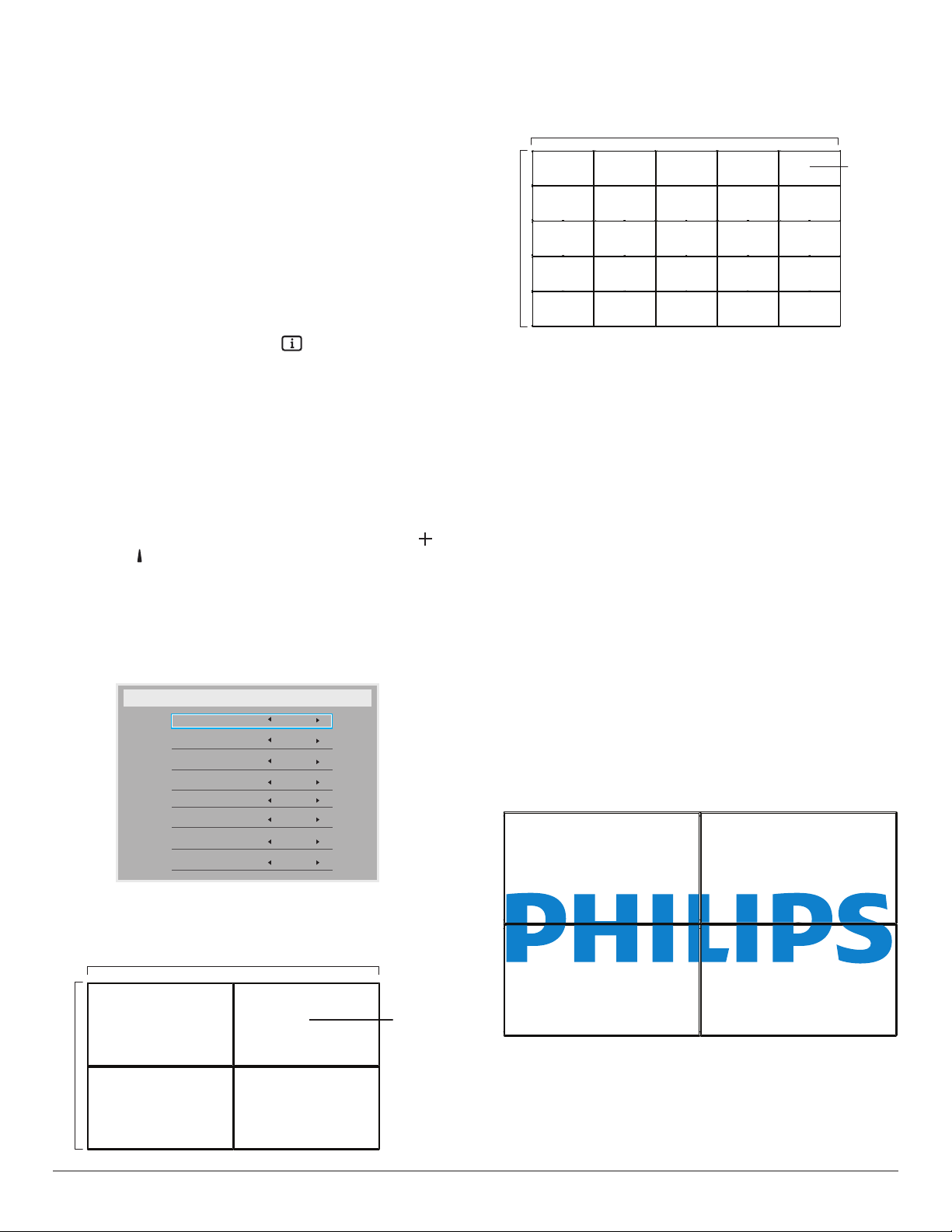
IR control
Select the operation mode of the remote control when multiple
displays are connected via an RS232C connection.
• {Normal} - All displays can be operated normally by the remote
control unit.
• {Primary} - Designate this display as the primary display for
remote control operation. Only this display can be operated by the
remote control. (In primary mode, IR key will always be processed
regardless the monitor id/group settings).
• {Secondary} - Designate this display as the secondary display. This
display can not be operated by the remote control, and will only
receive the control signal from the primary display via the RS232C
connection.
• {Lock All} / {Lock all but Volume} / {Lock all but Power} / {Lock
all except PWR & VOL}- Lock the remote control function of this
display. To unlock, press and hold the [ ] INFO button on the
remote control for 6 (six) seconds.
Keyboard control
Choose to enable or disable the display keyboard (control buttons)
function.
• {Unlock} - Enable the keyboard function.
• {Lock All} / {Lock all but Volume} / {Lock all but Power} / {Lock all
except PWR & VOL} - Disable the keyboard function.
NOTE: “Keyboard Control Lock Mode” This function completely
disables the access to all Keyboard Control functions. To
enable or disable the keyboard control lock, press both [ ]
and [ ] buttons and hold down continuously for more than 3
seconds.
Tiling
With this function you can create a single large-screen matrix (video
wall) that consists of up to 225 sets of this display (up to 15-sets on the
vertical and 15-sets on the horizontal sides). This function requires a
daisy-chain connection.
Example: 5 x 5 screen matrix (25 displays)
H monitors = 5 displays
V monitors = 5 displays
H monitors
1 2
6 7
3 4
8 9
5
10
Position
11 12 13 14 15
V monitors
16 17 18 19 20
21 22 23 24 25
• {Switch on delay} - Set the power-on delaying time (in seconds).
The default option {Auto} allows a sequential powering-on for each
display by their ID number when multiple displays are connected.
The options are: {Off/Auto/2-255}
• Brightness: {Normal}/{ACS}
{Normal}: Apply OSD brightness value (backlight)
{ACS}: Apply brightness value (backlight) which is adjusted by MIC
tool. The default value before adjustment is the same as OSD
brightness value, e.g., 70)
Some brightness (backlight) settings cannot be adjusted by OSD.
Please refer to Picture Menu Backlight setting priority.
• Type: {Off}/{SW Tool}/{OSD Only}
• {Enable} - Choose to enable or disable the Tiling function. If enabled,
the display will apply the settings in {H monitors}, {V monitors},
{Position}, and {Frame comp.}.
• {H monitors} - Select the number of displays on the horizontal side.
• {V monitors} - Select the number of displays on the vertical side.
• {Position} - Select the position of this display in the screen matrix.
• {Frame comp.} - Choose to turn the frame compensation
function on or off. If selected {Ye s }, the display will adjust the image
to compensate for the width of the display bezels in order to
accurately display the imag
Frame compensation - Yes
Example: 2 x 2 screen matrix (4 displays)
H monitors = 2 displays
V monitors = 2 displays
H monitors
1 2
V monitors
3 4
Position
53
Page 65
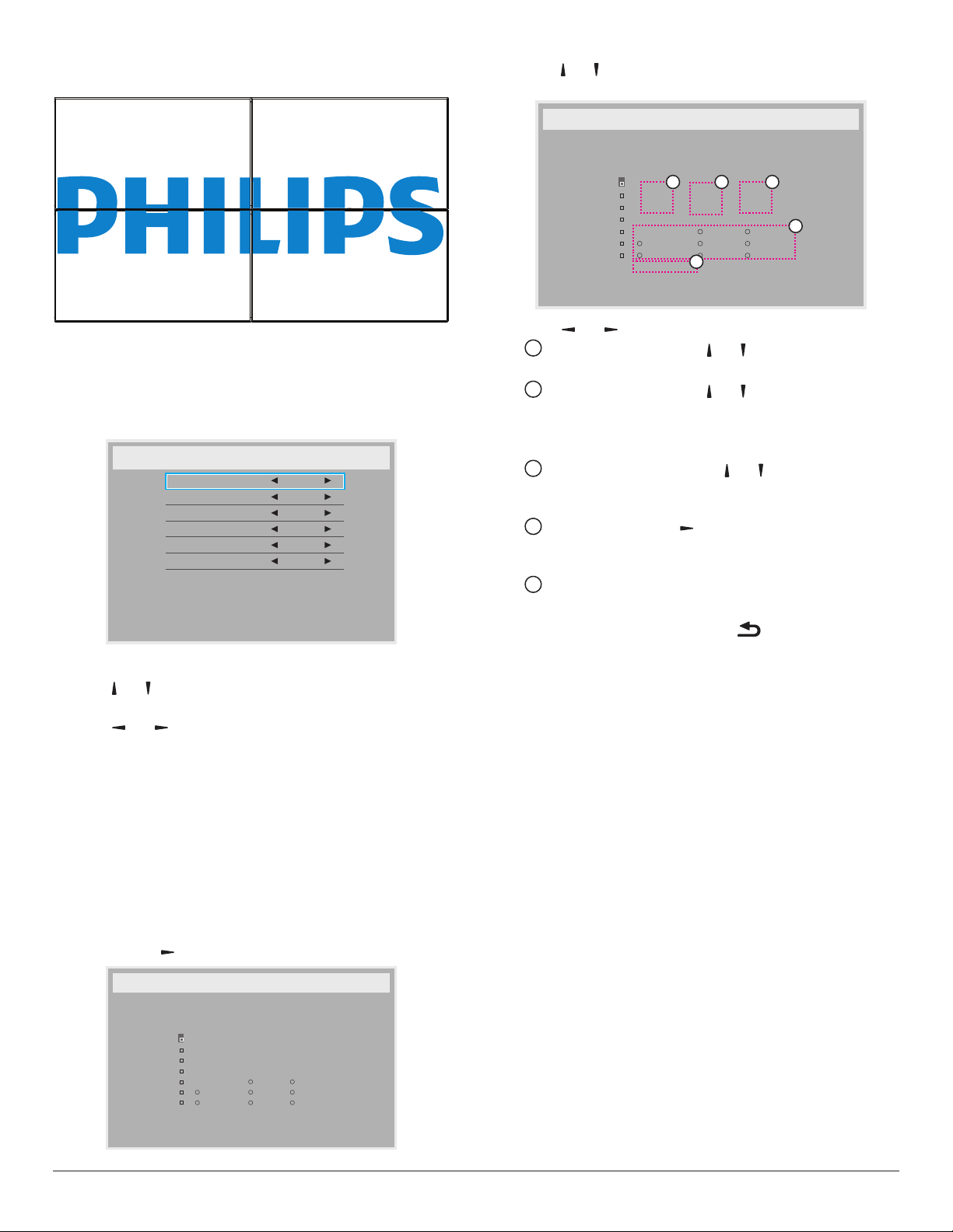
Frame compensation - No
Off Timer
Set automatically power off time (in hours).
Date and time
Adjust the current date and time for the display’s internal clock.
O
:
MON
THU
SUN
Input
_
TUE
FRI
Every week
Clear all
1. Press [OK] button to enter the submenu.
2. Press [ ] or [ ] button to toggle between {Year}, {Month}, { Day},
{Hour}, {Minute}.
3. Press [ ] or [ ] button to adjust settings.
Schedule
This function allows you to program up to 7 (seven) different scheduled
time intervals for the display to activate.
You can select:
• The time for the display to turn on and turn off.
• The days in a week for the display to activate.
• Which input source the display will use for each scheduled
activation period.
NOTE: We recommend you to set up current date and time in the
{Date and time} menu before using this function.
1. Press [OK] or [ ] button to enter the submenu.
Schedule
Today
2015 . 01 . 04 SUN 04 : 14 : 01
1
2
On
:
_ _ _ _
3
4
5
6
WED
7
SAT
playlist 0
2. Press [ ] or [ ] button to select a schedule item (item number 1 ~ 7),
and then press [OK] button to mark it the item number.
Schedule
Today
2015 . 01 . 04 SUN 04 : 14 : 01
1
1
2
On
:
_ _ _ _
3
4
5
6
WED
7
SAT
playlist 0
O
:
MON
THU
SUN
5
Input
_
TUE
FRI
Every week
Clear all
32
4
3. Press [ ] or [ ] button to select the schedule:
1
Power-on schedule: Press [ ] or [ ] button to set the hour
and minute for the display to turn on.
2
Power-off schedule: Press [ ] or [ ] button to set the hour
and minute for the display to turn off.
Select or leave an empty “__” for both the hour and minute slot if
you do not want to use this power-on or power-off schedule.
3
Input-source selection: Press [ ] or [ ] button to select an
input source. If no input source is selected, the input source
will remain the same as last selected.
4
Date schedule: Press [ ] button to select which day in a
week this schedule item will be take effect, and then press the
[OK] button.
5
When Input-source select to USB, enable to access playlist
setting:
For additional schedule settings, press [ ], then repeat the steps
4.
above. A check mark in the box next to the number of the schedule
item indicates that the selected schedule is in effect.
NOTES:
• If the schedules overlap, the scheduled power-on time takes priority
over scheduled power-off time.
• If there are two schedule items programmed for the same time, the
highest numbered schedule takes priority. For example, if schedule
items #1 and #2 both set the display to power on at 7:00 AM and
off at 5:00 PM, then only schedule item # 2 will take effect.
HDMI with One Wire
CEC control.
• {Off} - Disable CEC.(Default)
• {On} - Enable CEC.
Auto signal detection
Choose to let the display detect and display available signal sources
automatically.
• {Off} - Once a signal is connected, it can only be selected manually.
If the selected input is no signal, set the display to display the image
automatically according to the search order of each option.
The options are: {All} / {Failover}
• {All}: DP -> HDMI1 -> HDMI2 -> DVI -> VGA ->Media Player ->
Browser -> SmartCMS -> PDF Reader -> Custom.
• {Failover}
- Failover 1: User-dened setting. Default:HDMI 1.
- Failover 2: User-dened setting. Default:HDMI 1.
54
Page 66
- Failover 3: User-dened setting. Default:HDMI 1.
- Failover 4: User-dened setting. Default:HDMI 1.
- Failover 5: User-dened setting. Default:HDMI 1.
- Failover 6: User-dened setting. Default:HDMI 1.
- Failover 7: User-dened setting. Default:HDMI 1.
- Failover 8: User-dened setting. Default:HDMI 1.
- Failover 9: User-dened setting. Default:HDMI 1.
- Failover 10: User-dened setting. Default:HDMI 1.
Power Save
Power save modes
Mode 1: [TCP off, WOL on, auto off]
DC off -> Power off. LED: Red.
Power Save -> Power off, LED: Red
Mode 2: [TCP off, WOL on, auto on/off]
DC off -> Power off, LED: Red.
Power Save -> Power Saving. LED: Orange. Can be wake up.
Mode 3: [TCP on, WOL off, auto on/off]
DC off -> Back light off, LED: Red
Power Save -> Back light off, LED: Orange. Can be wake up.
Mode 4: [TCP on, WOL off, no auto on/off]
DC off -> Back light off, LED: Red
Power Save -> Will not enter power save mode. show “no
signal” only.
Mode 3
DC OFF:
Backlight Off only
Power Save:
Backlight Off only
Mode 4
DC OFF:
Backlight Off only
Power Save:
No signal(Backlight On)
Following table is the action for Android board with different power
mode.
DC off/on: Press power button by RC
Power mode in OSD Mode 1/2 Mode 3/4
DC off shutdown The current source APK(such
DC on Boot up Android system reboots
Mode 1(default)
DC OFF:
Power Off
Power Save:
Power Off
Mode 2
DC OFF:
Power Off
Power Save:
Power Saving
as MediaPlayer, Browser, PDF,
SmartCMS or Custom) will be
closed.
Import: Copy settings from le to display
Export: Copy PD settings into le.
* Cloned data stores in android internal storage. User need to use APK
to copy cloned data to another display.
Advanced option reset
Reset all settings except {Date and Time} in the Advanced option menu
to factory preset values.
1. Press [OK] or [ ] button to enter the submenu.
2. Press [ ]
button to restore settings to factory preset values.
Press the [ ] button or select {Cancel} and press the [OK]
3.
button to cancel and then return to the previous menu.
or [ ] button to select {Reset} and press the [OK]
Scalar FW Update
Update scalar FW by USB.
USB cloning
Copy PD settings from one set to another.
55
Page 67
7. Supported Media Formats
USB Multimedia Codec Formats
Video Decode
Type Video Codec Container Decode Encode Channel
MPEG program stream
(.DAT, .VOB, .MPG, .MPEG)
MPEG1/2 MPEG1/2
MPEG-4 MPEG4
H.263 H.263
H.264 H.264
H.265 H.265
GOOGLE VP8 VP8 MKV (.mkv) WebM (.webm) V
Motion JPEG MJPEG
MPEG transport stream (.ts)
MP4 (.mp4)
AVI (.avi)
MKV (.mkv)
MP4 (.mp4)
AVI (.avi)
MKV (.mkv)
FLV (.v)
AVI (.avi)
FLV (.v)
MP4 (.mp4)
MPEG transport stream (.ts)
ASF (.asf)
WMV (.wmv)
AVI (.avi)
MKV (.mkv)
MP4 (.mp4)
MPEG transport stream (.ts)
MKV (.mkv)
AVI (.avi)
MP4 (.mp4) MKV (.mkv)
V
V
V
V
V
V
Remark
Max Resolution: 1080P@60fps
Max Bit Rats : 40Mbps
Max Resolution: 1080P@60fps
Max Bit Rats : 40Mbps
Max Resolution: 1080P@60fps
Max Bit Rats : 40Mbps
Max Resolution: 1080P@60fps
Max Bit Rats : 135Mbps
4K2K@30fps
Max Resolution: 4K2K@60fps
Max Bit Rats : 100Mbps
Max Resolution: 1080P@30fps
Max Bit Rats : 20Mbps
Max Resolution: 1920*1080 @30fps
Max Bit Rats : 40Mbps
Audio Decode
Type Audio Codec Container Decode Encode Channel Remark
MPEG Audio
Windows
Media Audio
AAC Audio
MPEG1/2/2.5 Audio
Layer1/2/3
WMA Version 7, 8,
9,10 pro M0, 10Pro
M1,M10 Pro M2
MAIN, ADIF ,ATDS
Header AAC-LC and
AAC-HE
MP3 V 2
Decode: WMA V 2
File Format: AAC, M4A V 5.1
Bit Rate: 8Kbps~320Kbps
Sampling Rate: 16KHz~48KHz
Bit Rate: 8Kbps~768Kbps
Sampling Rate: 8KHz~96(M10)KHz
Non-support LBR
Bit Rate: N/A
Sampling Rate: 8KHz~48KHz
56
Page 68
Image Decode
Type Image Codec Photo Decode Encode Channel Remark
Max Resolution: 7000 x 7000
JPEG JFIF le format 1.02 File Format: JPG, JPEG V
BMP BMP File Format: BMP V
PNG PNG File Format: PNG V
NOTES:
• Sound or video may not work if the contents have a standard bit rate/frame rate above the compatible Frame/sec listed in the table above.
• Video content with a Bit rate or Frame rate larger than the rate specied in the table above can cause choppy video during playback.
The limitation of max resolution depends on
DRAM
Max Resolution: 15360 x 8640
The limitation of max resolution depends on
DRAM
Max Resolution: 15360 x 8640
The limitation of max resolution depends on
DRAM
57
Page 69
8. Input Mode
VGA/DVI timing support:
Item Mode Resolution H.Freq. (KHz) V.Freq. (Hz)
1 IBM VGA 10H 640x350 31.469 70.086
2 IBM VGA 12H 640x480 31.469 59.94
3 MACINTOSH 640x480 35 66.67
4 VESA 640x480 37.861 72.809
5 VESA 640x480 37.5 75
6 IBM VGA 3H 720x400 31.469 70.087
7 VESA 800x600 35.156 56.25
8 VESA 800x600 37.879 60.317
9 VESA 800x600 48.077 72.188
10 VESA 800x600 46.875 75.000
11 MACINTOSH 832x624 49.726 74.551
12 VESA Standard AddDMT 848x480 31 60.000
13 - 960x720 56.4 75.000
14 VESA 1024x768 48.363 60.004
15 VESA 1024x768 56.476 70.069
16 1152x864 53.986 59.985
17 VESA 1152x864 53.783 59.959
18 1152x864 63.851 70.012
19 VESA 1152x864 67.5 75.000
20 SUN WS 1152x900 61.846 66.004
21 - 1280x720 44.772 60.000
22 - 1280x720 52.5 70.000
23 CVT 2.3MA 1280 x768 47.776 59.870
24 CVT 2.3MA 1280 x768 60.289 74.893
25 CVT 1280x800 49.7 59.810
26 CVT 1280x800 62.8 74.930
27 VESA 1280x960 60 60.000
28 VESA 1280x1024 63.981 60.020
29 SUN WS 1280x1024 71.691 67.189
30 VESA 1280x1024 79.976 75.025
31 VESA Standard AddDMT 1360x768 47.712 60.015
32 VESA Standard AddDMT 1366x768 47.712 59.790
33 VESA-reduced blanking mode 1440x900 55.469 59.901
34 VESA 1440x900 55.935 59.887
35 VESA 1440x900 70.635 74.984
36 CVT-reduced blanking 1400x1050 64.744 59.948
37 CVT 1400x1050 82.278 74.867
38 CVT Red. Blanking 1600x900 55.54 60.000
39 VESA 1600x1200 75 60
40 CVT1.76MW 1680x1050 65.29 59.954
41 CVT1.76MW-R 1680x1050 64.674 59.883
42 CVT 2.3MA-R 1920x1080 66.587 59.934
43 VESA Standard VDMTREV 1920x1080 67.5 60.000
44 CVT1960H 1920x1080 67.1584 59.963
45 VSC1960H 1920x1080 67.08 60
46 CVT 2.3MA-R 1920x1200 74.038 59.950
58
Page 70
Video Timing suppor t(HDMI/DVD HD/DVI)
Item Mode Resolution Comment
1 60Hz 480i except DVI
2 480p
3 720p
4 1080i
5 1080p
6 50Hz 576i except DVI
7 576p
8 720p
9 1080i
10 1080p
• The PC text quality is optimum in FHD 1920 x 1080, 60Hz.
• Your PC display screen might appear different depending on the manufacturer (and your particular version of Windows).
• Check your PC instruction book for information about connecting your PC to a display.
• If a vertical and horizontal frequency-select mode exists, select 60Hz (vertical) and 31.5KHz (horizontal). In some cases, abnormal signals (such as
stripes) might appear on the screen when the PC power is turned off (or if the PC is disconnected). If so, press the [INPUT] button to enter the
video mode. Also, make sure that the PC is connected.
• When horizontal synchronous signals seem irregular in RGB mode, check PC power saving mode or cable connections.
• The display settings table complies to the IBM/VESA standards, and based on the analog input.
• The DVI support mode is regarded as same to the PC support mode.
• The best timing for the vertical frequency to each mode is 60Hz.
• YCbCr 444 BT2020 Non-const is not supported.
59
Page 71
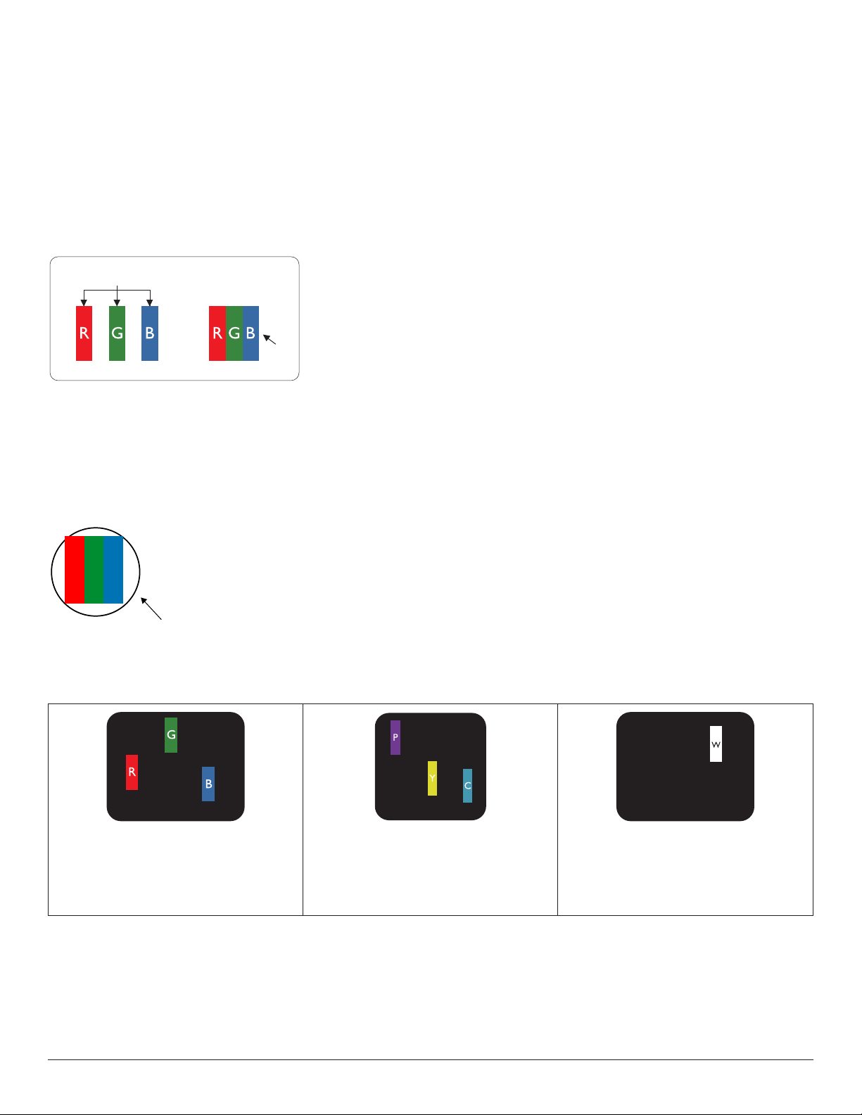
9. Pixel Defect Policy
We strive to deliver the highest quality products and use some of the industry’s most advanced manufacturing processes whilst practicing stringent quality
control. However, pixel or sub-pixel defects on the PDP / TFT panels used in Plasma- & LCD- displays are sometimes unavoidable. No manufacturer can
guarantee that all panels will be free from pixel defects, but Philips guarantees that any Plasma- & LCD- displays with an unacceptable number of defects
will be repaired during the warranty period in line with your local guarantee conditions.
This notice explains the different types of pixel defects and denes the acceptable defect level for the LCD screen. In order to qualify for repair under
warranty, the number of pixel defects must exceed a certain level as shown in the reference table. If the LCD screen is within specication a warranty
exchange / claim back will be refused. Additionally, because some types or combinations of pixel defects are more noticeable than others, Philips sets even
higher quality standards for those.
9.1. Pixels and Sub-Pixels
subpixel
pixel
9.2. Types of Pixel Defects + Dot Definition
Pixel and sub-pixel defects appear on the screen in different ways. There are three categories of pixel defects and several types of sub-pixel defects within
each category.
Dot denition = What is a defective “Dot”? :
One or more defective, adjacent sub-pixel are dened as one “dot”. The no. of defective sub-pixels are not relevant to dene a defective dot. This means
that a defective dot can consist of one, two or three defective sub-pixels which can be dark or lit.
A pixel, or picture element, is composed of three sub-pixels in the primary colors of red, green and
blue. Many pixels together form an image. When all sub-pixels of a pixel are lit, the three colored
sub-pixels together appear as a single white pixel. When all are dark, the three colored sub-pixels
together appear as a single black pixel. Other combinations of lit and dark sub-pixels appear as
single pixels of other colors.
RR G B
One dot = One Pixel; consists of three sub-pixels of Red, Green, and Blue.
9.3. Bright Dot Defects
Bright dot defects appear as pixels or sub-pixels that are always lit or “on”. These are the examples of bright dot defects:
One lit red, green or blue sub pixel Two adjacent lit sub pixels:
Red + Blue = Purple
Red + Green = Yellow
Green + Blue = Cyan (Light Blue)
Three adjacent lit sub pixels (one white pixel)
60
Page 72
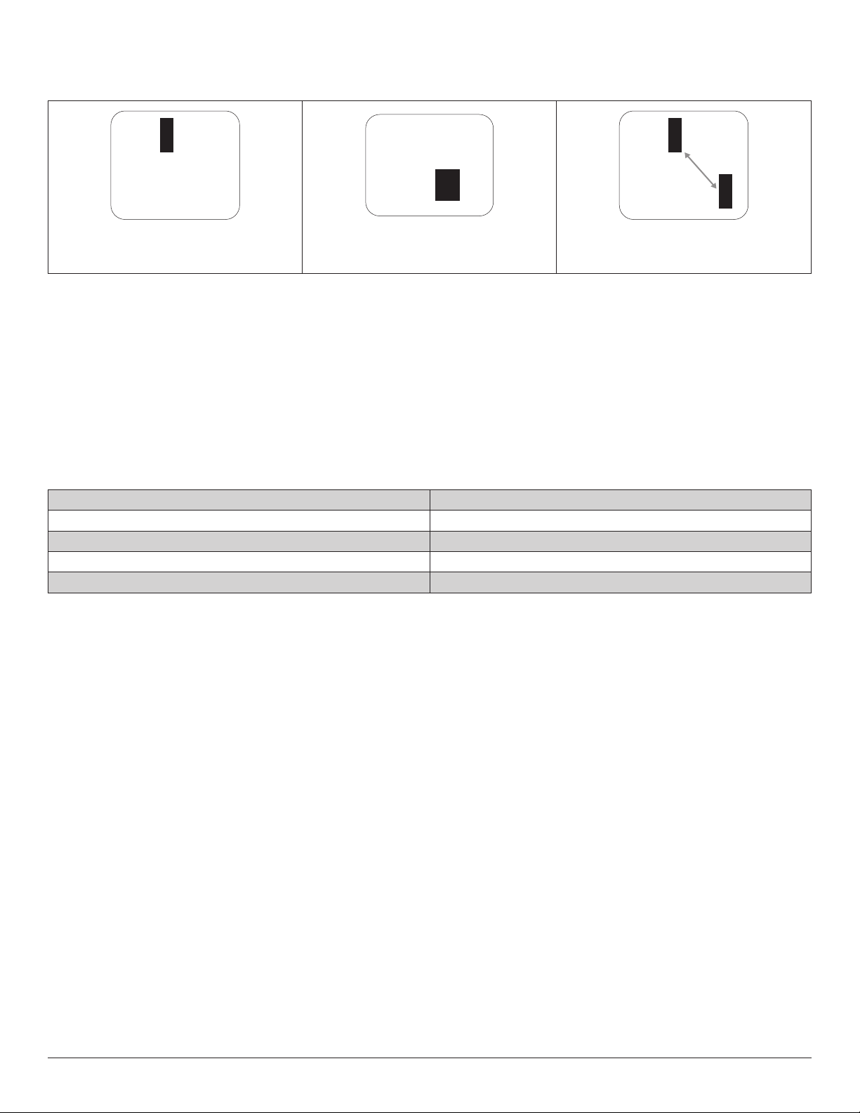
9.4. Dark Dot Defects
Black dot defects appear as pixels or sub-pixels that are always dark or “off”. These are the examples of black dot defects:
One dark dot Two adjacent dark dots = 1 pair of dark dots Two dark dots, specications denes the
minimum distance between dark dots
9.5. Proximity of Pixel Defects
Because pixel and sub-pixels defects of the same type that are nearby one another may be more noticeable, Philips also species tolerances for the
proximity of pixel defects. In the table below you can nd specications about:
• Allowed amount of adjacent dark dots = (adjacent dark dots =1 pair of dark dots)
• Minimum distance between dark dots
• Total no. of all defective dots
9.6. Pixel Defect Tolerances
In order to qualify for repair due to pixel defects during the warranty period, a PDP / TFT panel in a Philips Plasma / LCD- display must have pixel or sub-
pixel defects exceeding the tolerances listed in the following table.
BRIGHT DOT EFFECT ACCEPTABLE LEVEL
1 lit sub pixel 2
BLACK DOT EFFECT ACCEPTABLE LEVEL
1 dark sub pixel 10
TOTAL DOT DEFECTS OF ALL TYPES 12
NOTE: * 1 or 2 adjacent sub pixel defects = 1 dot defect
9.7. MURA
Dark spots or patches may occasionally appear on some liquid crystal display (LCD) panels. This is known within the industry as Mura, which is a Japanese
term for “unevenness.” It is used to describe an irregular pattern or area in which uneven screen uniformity appears under certain conditions. Mura is a
result of the deterioration of the liquid crystal alignment layer and is most commonly caused by long-term operation under high ambient temperatures. It
is an industry- wide phenomenon and Mura is not repairable. It is also not covered by our warranty terms.
Mura has been around since the introduction of LCD technology and with screens getting bigger and in operation 24/7, many displays are running in low
light conditions. This all adds to the possibility of Mura affecting displays.
HOW TO SPOT MURA
There are many symptoms of Mura and also multiple causes. Several of these are listed below:
• Impurities or foreign particles in the crystal matrix
• Uneven distribution of LCD matrix during manufacturing
• Non-uniform luminance distribution of the backlight
• Panel assembly induced stress
• Flaws within the LCD cells
• Thermal induced stress - high temperature operation over long periods of time
HOW TO AVOID MURA
Although we can not guarantee the complete eradication of Mura every time, in general the appearance of Mura can be minimized by these methods:
• Lower the backlight brightness
• Use a screen saver
• Reduce the ambient temperature around the unit
61
Page 73

10. Cleaning and Troubleshooting
10.1. Cleaning
Caution When Using the Display
• Do not bring your hands, face or objects close to the ventilation holes of the display. The top of the display is usually very hot due to the high
temperature of exhaust air being released through the ventilation holes. Burns or personal injuries may occur if any body parts are brought too
close. Placing any object near the top of the display could also result in heat related damage to the object as well as the display itself.
• Be sure to disconnect all cables before moving the monitor. Moving the monitor with its cables attached may damage the cables and thus cause
re or electric shock.
• Disconnect the power plug from the wall outlet as a safety precaution before carrying out any type of cleaning or maintenance procedure.
Front Panel Cleaning Instructions
• The front of the display has been specially treated. Wipe the surface gently using only a cleaning cloth or a soft, lint-free cloth.
• If the surface becomes dirty, soak a soft, lint-free cloth in a mild detergent solution. Wring the cloth to remove excess liquid. Wipe the surface of
the display to remove dirt. Then use a dry cloth of the same type to dry.
• Do not scratch or hit the surface of the panel with ngers or hard objects of any kind.
• Do not use volatile substances such as insert sprays, solvents and thinners.
Cabinet Cleaning Instructions
• If the cabinet becomes dirty, wipe the cabinet with a soft, dry cloth.
• If the cabinet is extremely dirty, soak a lint-free cloth in a mild detergent solution. Wring the cloth to remove as much moisture as possible. Wipe
the cabinet. Use another dry cloth to wipe over until the surface is dry.
• Do not allow any water or detergent to come into contact with the surface of the display. If water or moisture gets inside the unit, operating
problems, electrical and shock hazards may result.
• Do not scratch or hit the cabinet with ngers or hard objects of any kind.
• Do not use volatile substances such as insert sprays, solvents and thinners on the cabinet.
• Do not place anything made from rubber or PVC near the cabinet for any extended periods of time.
62
Page 74
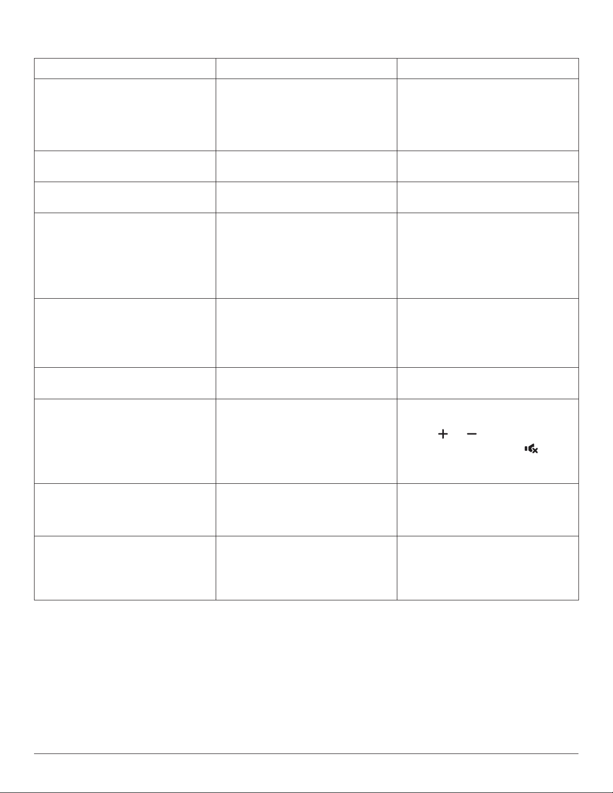
10.2. Troubleshooting
Symptom Possible Cause Remedy
No picture is displayed 1. The power cord is disconnected.
2. The main power switch on the back of the
display is not switched on.
3. The selected input has no connection.
4. The display is in the standby mode.
Interference displayed on the display or an
audible noise is heard
Color is abnormal The signal cable is not connected properly. Make sure that the signal cable is attached rmly
Picture is distorted with abnormal patterns 1. The signal cable is not connected properly.
Display image doesn’t ll up the full size of the
screen
Can hear sound, but no picture Source signal cable is connected improperly. Make sure that both video inputs and sound
Caused by surrounding electrical appliances or
uorescent lights.
2. The input signal is beyond the capabilities of
the display.
1. The zoom mode is not set correctly.
2. Scan Mode may be set incorrectly to
underscan.
3. If the image exceeds the screen size, Scan
Mode may need to be set to Underscan.
1. Plug in the power cord.
2. Make sure that the power switch is switched
on.
3. Connect a signal connection to the display.
Move the display to another location to see if the
interference is reduced.
to the back of the display.
1. Make sure that the signal cable is attached
rmly.
2. Check the video signal source to see if it
is beyond the range of the display. Please
verify its specications with this display’s
specication section.
Use the Zoom mode or Custom zoom function
in the Screen menu to ne tune display geometry
and time frequency parameter.
inputs are correctly connected.
Can see picture but no sound is heard 1. Source signal cable is connected improperly.
2. Volume is turned all the way down.
3. {Mute} is turned on.
4. No external speaker is connected.
Some picture elements do not light up Some pixels of the display are off. This display is designed using an extremely high
After-Images can still be seen on the display
after the display is powered off. (Examples
of still pictures include logos, video games,
computer images, and images displayed in 4:3
normal mode)
A still picture is displayed for an over extended
period of time
1. Make sure that both video inputs and sound
inputs are connected correctly.
2. Press [ ] or [ ] button to hear sound.
3. Switch MUTE off by using the [ ] button.
4. Connect external speakers and adjust the
volume to a suitable level.
level of precision technology: however, sometimes
some pixels of the display may not display. This is
not a malfunction..
Do not allow a still image to be displayed for
an extended period of time as this can cause a
permanent after-image to remain on the display.
63
Page 75
How to setup the settings in the menu to
control all the monitors at the same time and
individually via RC?
How is the RC working? Daisy chain: no connection of RS232 and IR cable No setting is required. Connect with IR cables
Daisy chained by RS232 and no IR cable 1. The rst display sets as “Primary” on OSD
(Advanced option/IR control item), others set as
“Secondary”.
2. The setup OSD will show on top left side of
the display.(Toggle MENU will show again if it
disappear)
3. Default setting: ID NO: 0, GP NO: 0, this setting
can control all displays by IR.
The “+”, “-” can change “ID NO” to control
signal display by “Monitor ID”.
The “UP”, “DOWN” can change “GP NO” to
control multi-display by “Group ID”.
*The rst display is always controlled by IR.
and control by IR.
*This may cause out-of-synchronizm
phenomenon. It is suggested to use the above
settings with RS-232 cable.
64
Page 76
11. Technical Specifications
Display:
Item
Screen Size (Active Area) 800.1 mm / 31.5 inches 1080 mm / 42.5 inches 1232 mm / 48.5 inches 1387 mm / 54.6 inches
Aspect Ratio 16:9 16:9 16:9 16:9
Number of pixels 1920 (H) x 1080 (V) 1920 (H) x 1080 (V) 1920 (H) x 1080 (V) 1920 (H) x 1080 (V)
Pixel pitch 0.36375 (H) x 0.36375 (V)
Displayable colors 16.7 million colors 16.7 million colors 16.7 million colors 16.7 million colors
Brightness (typical) 450 cd/m2 450 cd/m2 450 cd/m2 450 cd/m2
Contrast ratio (typical) 1100:1 1100:1 1100:1 1100:1
Viewing angle 178 degrees 178 degrees 178 degrees 178 degrees
32BDL4051D 43BDL4051D 49BDL4051D 55BDL4051D
0.4902 (H) x 0.4902 (V)
[mm]
[mm]
In/Out Terminals:
Item Specications
Speaker Output Internal Speakers 10W (L) + 10W (R) [RMS]/8Ω
82 dB/W/M/160 Hz ~ 13 KHz
Audio Output 3.5mm phone jack x 1 0.5V [rms] (Normal) / 2 Channel (L+R)
Audio Input 3.5mm phone jack x 1 0.5V [rms] (Normal) / 2 Channel (L+R)
RS232 2.5mm Phone jack x 2 RS232 in / RS232 out
RJ-45 RJ-45 Jack x 1 (8 pin) 1000 baseT
HDMI Input HDMI Jack x 2
(Type A) (19 pin)
Displayport in/out Displayport Jack x 2
(20 pin)
DVI-I(DVI-D & VGA)
Input
DVI-I (DVI-D & VGA)
Output
SD card Micro SD card Suppor t to 128GB
OTG Mini USB Service only
USB Input USB2.0 TypeA x1
DVI-I jack Digital RGB: TMDS (Video)
DVI-I Jack x 1 (29 pin) Digital RGB: TMDS (Video)
USB3.0 TypeA x1
Digital RGB: TMDS (Video + Audio)
MAX: Video - 720p, 1080p, 3840 x 2160/30 Hz
Audio - 48 KHz/ 2 Channel (L+R)
Supports LPCM only
Digital RGB: TMDS (Video + Audio)
MAX: Video - 720p, 1080p, 3840 x 2160/60 Hz
Audio - 48 KHz / 2 Channel (L+R)
Supports LPCM only
Analog RGB: 0.7V [p-p] (75Ω), H/CS/V: TTL (2.2kΩ), SOG: 1V [p-p] (75Ω)
MAX: 720p, 1080p, 1920 x 1080/60 Hz (WUXGA)
Analog RGB: 0.7V [p-p] (75Ω), H/CS/V: TTL (2.2kΩ), SOG: 1V [p-p] (75Ω)
MAX: 720p, 1080p, 1920 x 1080/60 Hz (WUXGA)
USB2.0
USB3.0
Specications
0.55926 (H) x 0.55926 (V)
[mm]
0.630 (H) x 0.630 (V) [mm]
65
Page 77
General:
Item
32BDL4051D 43BDL4051D 49BDL4051D 55BDL4051D
Power Input 100 - 240V~, 50 - 60Hz 100 - 240V~, 50 - 60Hz 100 - 240V~, 50 - 60Hz 100 - 240V~, 50 - 60Hz
Power Consumption (Max) 110 W 120 W 130 W 150 W
Power Consumption (typ.) 60 W 65 W 75 W 85 W
Power Consumption
<0.5 W <0.5 W <0.5 W <0.5 W
(Standby & Off)
Dimensions (Without
724.8 x 424.3 x 64.1 mm 965.0 x 559.3 x 45.5 mm 1097.6 x 633.9 x 45.5 mm 1233.4 x 710.3 x 45.5 mm
Stand) [W x H x D]
Weight (Without Stand) 6.15 Kg 10.4 Kg 14.8 Kg 18.0 Kg
Weight (With Stand) 8.25 Kg 14.5 Kg 18.9 Kg 22.1 Kg
Gross Weight 8.50 Kg 14.7 Kg 20.0 Kg 25.4 Kg
Energy Efciency Class B A A A
Visible Screen Size 800.1 mm / 31.5 inches 1080 mm / 42.5 inches 1232 mm / 48.5 inches 1387 mm / 54.6 inches
On Mode Power
55 W 65 W 75 W 85 W
Consumption (W)
Annual Energy
81 kWh 95 kWh 110 kWh 124 kWh
Consumption (kWh)
Standby Power
0.50 W 0.50 W 0.50 W 0.50 W
Consumption (W)
Off Mode Power
0 W 0 W 0 W 0 W
Consumption (W)
Display Resolution (Pixels) 1920 x 1080 1920 x 1080 1920 x 1080 1920 x 1080
Network Standby (W) 2 W 2 W 2 W 2 W
Specications
+
Environmental Condition:
Item Specications
Temperature Operational 0 ~ 40°C
Storage -20 ~ 60°C
Humidity Operational 20 ~ 80% RH (No condensation)
Storage 5 ~ 95% RH (No condensation)
Altitude Operational 0 ~ 3,000 m
Storage / Shipment 0 ~ 9,000 m
66
Page 78

2019 © Koninklijke Philips N.V. All rights reserved.
Philips and the Philips Shield Emblem are registered trademarks of
Koninklijke Philips N.V. and are used under license from
Koninklijke Philips N.V.
Specications are subject to change without notice.
 Loading...