

Page 1
IntelliVue Smart-hopping
N
e
t
w
o
r
k
p
o
w
e
r
/
S
y
n
c
R
a
d
i
o
A
c
ti
v
i
ty
L
i
n
k
10/100 48 VDC
IOIOI
Serial Service Port
Draft - August 28, 2013
1.4 GHz High-power Access Point
Installation Guide
Part Number: 453564459791
Printed in the U.S.A.
August, 2013
First Edition
453564459791
Page 2

Proprietary Information
Draft - August 28, 2013
This document contains proprietary information that is protected by copyright.
Copyright
Copyright © 2013 Koninklijke Philips N.V. All Rights Reserved.
Manufacturer
Philips Medical Systems
3000 Minuteman Road
Andover, MA 01810-1099
(+1) 978-687-1501
This document was printed in the United States of America.
Trademark Acknowledgements
All trademarks, trade names and company names referenced herein are used for identification purposes only and are the
property of their respective owners.
FCC Notice
These devices comply with part 15 of the FCC Rules. Operation is subject to the following two conditions: (1) these devices
may not cause harmful interference, and (2) these devices must accept any interference received, including interference
that may cause undesired operation.
Pursuant to Part 15.21 of the FCC Rules, any changes or modifications to this equipment not expressly approved by Philips
Medical Systems may cause harmful radio frequency interference, and void your authority to operate this equipment.
This device has been designed to operate with the antenna having the part number 453564079561 and having a maximum
gain of 3.2 dB. Antennas not included in this approved list or having a gain greater than 3.2 dB are strictly prohibited for use
with this device. The required antenna impedance is 50 ohms.
Warranty
The information contained in this document is subject to change without notice. Philips Medical Systems makes no warranty
of any kind with regard to this material, including, but not limited to, the implied warranties or merchantability and fitness for
a particular purpose. Philips Medical Systems shall not be liable for errors contained herein or for incidental or consequential
damages in connection with the furnishing, performance, or use of this material.
Printing History
New editions of this document will incorporate all material updated since the previous edition. The documentation printing
date and part number indicate its current edition. The printing date and edition number change when a new edition is
printed. The document part number changes when extensive technical changes are incorporated.
First Edition
................................................................................................................................................... August, 2013
ii
Page 3

Contents
Draft - August 28, 2013
Introduction . . . . . . . . . . . . . . . . . . . . . . . . . . . . . . . . . . . . . . . . . . . . . . . . . . . . . . . 1-2
A General Description of the IntelliVue Smart-hopping Core Access Point . . . . . 1-3
Core AP Mounting Options . . . . . . . . . . . . . . . . . . . . . . . . . . . . . . . . . . . . . . . . 1-4
Power Source . . . . . . . . . . . . . . . . . . . . . . . . . . . . . . . . . . . . . . . . . . . . . . . . . . 1-4
Synchronization Signal . . . . . . . . . . . . . . . . . . . . . . . . . . . . . . . . . . . . . . . . . . . 1-4
IntelliVue Patient Monitor Mobility. . . . . . . . . . . . . . . . . . . . . . . . . . . . . . . . . . 1-4
Technical Alerts . . . . . . . . . . . . . . . . . . . . . . . . . . . . . . . . . . . . . . . . . . . . . . . . . 1-5
Firmware Updates. . . . . . . . . . . . . . . . . . . . . . . . . . . . . . . . . . . . . . . . . . . . . . . 1-5
Management Interfaces . . . . . . . . . . . . . . . . . . . . . . . . . . . . . . . . . . . . . . . . . . 1-5
Connectors and Status Indicators . . . . . . . . . . . . . . . . . . . . . . . . . . . . . . . . . . . . . 1-6
IntelliVue Smart-hopping Core AP Connectors . . . . . . . . . . . . . . . . . . . . . . . . 1-6
Remote AP Connectors. . . . . . . . . . . . . . . . . . . . . . . . . . . . . . . . . . . . . . . . . . . 1-7
IntelliVue Smart-hopping Core AP Status LEDs. . . . . . . . . . . . . . . . . . . . . . . . 1-8
Remote Antenna Status LEDs . . . . . . . . . . . . . . . . . . . . . . . . . . . . . . . . . . . . . 1-8
Specifications. . . . . . . . . . . . . . . . . . . . . . . . . . . . . . . . . . . . . . . . . . . . . . . . . . . . . . 1-9
Ordering Information . . . . . . . . . . . . . . . . . . . . . . . . . . . . . . . . . . . . . . . . . . . . . . . 1-11
Regulatory Information . . . . . . . . . . . . . . . . . . . . . . . . . . . . . . . . . . . . . . . . . . . . . 1-12
Access Point Placement Guidelines . . . . . . . . . . . . . . . . . . . . . . . . . . . . . . . . . . . . 2-2
General Installation Procedure. . . . . . . . . . . . . . . . . . . . . . . . . . . . . . . . . . . . . . . . 2-3
Mounting the IntelliVue Smart-hopping Core AP to a Wall (Fixed Mount) . . . . . . 2-6
Mounting the IntelliVue Smart-hopping Core AP to a Wall
(CA Earthquake Rated) . . . . . . . . . . . . . . . . . . . . . . . . . . . . . . . . . . . . . . . . . . . . . . 2-7
Mounting the IntelliVue Smart-hopping Core AP Above a Ceiling Tile . . . . . . . . . 2-9
Mounting the IntelliVue Smart-hopping Core AP Below a Ceiling Tile
(Fixed Mount) . . . . . . . . . . . . . . . . . . . . . . . . . . . . . . . . . . . . . . . . . . . . . . . . . . . . . 2-12
Mounting the IntelliVue Smart-hopping Core AP Below a Ceiling Tile
(Quick Release) . . . . . . . . . . . . . . . . . . . . . . . . . . . . . . . . . . . . . . . . . . . . . . . . . . . 2-16
Mounting the IntelliVue Smart-hopping Remote Antenna to a Wall
(Fixed Mount) . . . . . . . . . . . . . . . . . . . . . . . . . . . . . . . . . . . . . . . . . . . . . . . . . . . . . 2-21
Mounting the IntelliVue Smart-hopping Remote Antenna to a Wall
(CA Earthquake Rated) . . . . . . . . . . . . . . . . . . . . . . . . . . . . . . . . . . . . . . . . . . . . . 2-23
Mounting the IntelliVue Smart-hopping Remote Antenna Above a Ceiling Tile
(Mounting Rails). . . . . . . . . . . . . . . . . . . . . . . . . . . . . . . . . . . . . . . . . . . . . . . . . . . 2-25
Mounting the IntelliVue Smart-hopping Remote Antenna Above a Ceiling Tile
(Tether Mount) . . . . . . . . . . . . . . . . . . . . . . . . . . . . . . . . . . . . . . . . . . . . . . . . . . . . 2-28
Mounting the IntelliVue Smart-hopping Remote Antenna Below a Ceiling Tile
IntelliVue Smart-hopping 1.4 GHz High-power Access Point Installation Guide iii
Page 4

Contents
Draft - August 28, 2013
(Fixed Mount) . . . . . . . . . . . . . . . . . . . . . . . . . . . . . . . . . . . . . . . . . . . . . . . . . . . . . 2-30
Mounting the IntelliVue Smart-hopping RA Below a Ceiling Tile
(Quick Release) . . . . . . . . . . . . . . . . . . . . . . . . . . . . . . . . . . . . . . . . . . . . . . . . . . . 2-34
AP Configuration Information . . . . . . . . . . . . . . . . . . . . . . . . . . . . . . . . . . . . . . . . 2-37
Access Point Startup Sequence . . . . . . . . . . . . . . . . . . . . . . . . . . . . . . . . . . . . . . 2-37
Maintenance Procedure . . . . . . . . . . . . . . . . . . . . . . . . . . . . . . . . . . . . . . . . . . . . . 3-2
Troubleshooting the Core AP Using its LEDs . . . . . . . . . . . . . . . . . . . . . . . . . . . . . 3-2
Troubleshooting the Remote Antenna Using its LEDs . . . . . . . . . . . . . . . . . . . . . 3-3
Replacing a Core AP or Remote Antenna. . . . . . . . . . . . . . . . . . . . . . . . . . . . . . . . 3-4
Ordering Replacement Parts. . . . . . . . . . . . . . . . . . . . . . . . . . . . . . . . . . . . . . . . . . 3-4
Philips Sales and Support Offices Worldwide . . . . . . . . . . . . . . . . . . . . . . . . . . . . 3-6
CORPORATE HEADQUARTERS:. . . . . . . . . . . . . . . . . . . . . . . . . . . . . . . . . . . . . 3-6
UNITED STATES: . . . . . . . . . . . . . . . . . . . . . . . . . . . . . . . . . . . . . . . . . . . . . . . . 3-6
CANADA:. . . . . . . . . . . . . . . . . . . . . . . . . . . . . . . . . . . . . . . . . . . . . . . . . . . . . . . 3-6
EUROPE, MIDDLE EAST AND AFRICA: . . . . . . . . . . . . . . . . . . . . . . . . . . . . . . . 3-6
LATIN AMERICA HEADQUARTERS: . . . . . . . . . . . . . . . . . . . . . . . . . . . . . . . . . . 3-6
ASIA PACIFIC HEADQUARTERS: . . . . . . . . . . . . . . . . . . . . . . . . . . . . . . . . . . . . 3-6
iv
Page 5

About This Guide
Draft - August 28, 2013
This IntelliVue Smart-hopping 1.4 GHz High-power Access Point
Installation Guide provides complete instructions and procedures for
installing the Philips IntelliVue Smart-hopping 1.4 GHz Core Access Point
and Remote Antennas. This section describes the document and includes:
• Audience
•Document Organization
• Notational Conventions
• Related Documentation
•Terminology
IntelliVue Smart-hopping 1.4 GHz High-power Access Point Installation Guide v
Page 6

About This Guide
Draft - August 28, 2013
Audience
The IntelliVue Smart-hopping 1.4 GHz High-power Access Point
Installation Guide is written for trained service personnel who will install
the IntelliVue Smart-hopping 1.4 GHz Core Access Point as part of an
overall IntelliVue Smart-hopping deployment.
Document Organization
The information in this guide is organized and presented as follows:
• Chapter 1, Overview, describes the IntelliVue Smart-hopping 1.4 GHz
• Chapter 2, Installing the IntelliVue Smart-hopping 1.4 GHz Access
Core Access Point and how it is used to provide a bi-directional data
flow between the IntelliVue Information Center and IntelliVue Patient
Monitors.
Point, provides procedures to physically install the Philips IntelliVue
Smart-hopping 1.4 GHz Core Access Point and includes instructions
for mounting the Core AP and Remote Antennas to a wall, above a
ceiling tile, and below a ceiling tile.
• Chapter 3, Maintaining the IntelliVue Smart-hopping 1.4 GHz Core
Notational Conventions
This guide uses the following notational conventions to convey
information:
Note
Caution Cautionary statements call attention to a condition that could result in loss
Warning
Notes call attention to important information.
of data or damage to equipment.
Warnings call attention to a condition that could result in physical injury.
Access Point, provides procedures to maintain and troubleshoot
operation of the Philips IntelliVue Smart-hopping 1.4 GHz Core Access
Point.
vi
Page 7

Related Documentation
Draft - August 28, 2013
Please refer to these other documents for additional installation service
information about the IntelliVue Smart-hopping infrastructure:
• IntelliVue Smart-hopping Access Point Controller Installation Guide -
• IntelliVue Smart-hopping 2.4 GHz Access Point Installation Guide -
• IntelliVue Smart-hopping Infrastructure Installation and Service Guide
• IntelliVue Smart-hopping Sync Unit Installation Guide - lists procedures
About This Guide
provides procedures to physically install and power the IntelliVue
Smart-hopping Access Point Controller at the clinical site.
gives procedures to install the IntelliVue Smart-hopping 2.4 GHz AP at
the clinical site to a wall, or above or below a ceiling tile.
- provides complete information and procedures to install, configure,
inter-connect, and deploy the IntelliVue Smart-hopping infrastructure
at the clinical site. This document includes site planning guidelines,
procedures for use of the APC command line and graphical user
interfaces, AP configuration procedures, and APC and AP firmware
deployment procedures.
to install the IntelliVue Smart-hopping Sync Unit at the clinical site.
• Upgrading IntelliVue Smart-hopping Access Point Controllers and
Access Points - gives procedures to use the Philips IntelliVue Smart-
hopping APC and AP Upgrade Tool to install and synchronize the
firmware version on IntelliVue Smart-hopping APCs and APs.
IntelliVue Smart-hopping 1.4 GHz High-power Access Point Installation Guide vii
Page 8

About This Guide
Draft - August 28, 2013
Terminology
Please note the following terms, acronyms, and abbreviations used
throughout this document and in related documentation:
• Access Point (AP) - An IntelliVue Smart-hopping component that
provides bi-directional wireless access to the monitoring network for
IntelliVue Patient Monitors.
• Access Point Controller (APC) - An IntelliVue Smart-hopping component
used to manage the operation of the Access Points. One APC is
elected the Master APC. The Master APC supports the web interface to
the system and manages the master configuration.
• Access Point Group/AP Group - A logical grouping of APs. AP members
of the same AP Group will inherit common configuration settings
(defaults). AP groups will often map logically to the clinical units in
which the IntelliVue Smart-hopping Infrastructure is being installed.
• Database Domain (DBSD) - This term is used to describe the
“network” that contains the Standalone IntelliVue Information Center,
or the IntelliVue Database Server and its connected Information
Centers, Clients, bedsides, and infrastructure. This term applies to
both routed and non-routed topologies.
• IntelliVue Clinical Network (ICN) - This term refers to the entire
IntelliVue network. In a routed topology, the ICN includes the routers
and all inter-connected Database Domain(s) and the IntelliVue Smarthopping Infrastructure wireless subnet.
• IntelliVue Patient Monitor (IPM) - The IntelliVue Patient Monitor relays
real-time physiological waveforms and trends to the Philips IntelliVue
Information Center (PIIC) or Philips IntelliVue Information Center iX
(PIIC iX).
• IntelliVue Smart-hopping infrastructure - Philips proprietary wireless
network designed for continuous monitoring that provides two-way
communications between IntelliVue Patient Monitors, and the
IntelliVue Information Center.
• IntelliVue Smart-hopping Infrastructure Service Tool - The software
used to upgrade IntelliVue Smart-hopping APCs and APs, verify that
APCs on your network are configured correctly, and display warning
and error messages that you may use to troubleshoot any
configuration errors that may exist on your IntelliVue Smart-hopping
network. The IntelliVue Smart-hopping Infrastructure Service Tool is
also referred to as the Upgrade Tool. This tool was previously referred
to as the Upgrade Wizard.
• IntelliVue Telemetry System (ITS) - Deprecated term for the cellular
wireless architecture that provides two-way communications between
IntelliVue Patient Monitors, and the IntelliVue Information Center. See
IntelliVue Smart-hopping infrastructure.
• IntelliVue Wireless Subnet - This term is used to describe the IntelliVue
Smart-hopping Infrastructure “network” that contains the
viii
Page 9

About This Guide
Draft - August 28, 2013
infrastructure used in a routed topology to connect IntelliVue Smarthopping Infrastructure devices.
• Partnered APC - Configurable element within an AP Group used to
determine which APC will manage the operation of the AP members of
a particular AP Group.
• Power over Ethernet (PoE) Switch - The Power over Ethernet (PoE)
Switch is a 24-port Power-over-Ethernet device that provides 48 VDC
power to IntelliVue Access Points (and also remote Sync Units if
connected) via 100-Base-TX Ethernet LAN cabling. For systems using a
Power over Ethernet Switch, the ITS4844A Tele Synchronization Unit is
required to use the PoE feature of the PoE Switch.
• Power over Ethernet (PoE) Unit - The Power over Ethernet (PoE) Unit is
a 6- or 12-port Power-over-Ethernet device that provides 48 VDC power
to IntelliVue Access Points (and also remote Sync Units if connected)
via 100-Base-TX Ethernet LAN cabling.
• RF Access Code - Configurable element in the IntelliVue Smarthopping AP defaults shared among APs and IntelliVue Patient Monitors
to control wireless access to the monitoring network. Portable devices
will only connect to access points with which they share access codes.
The RF Access Code allows a specific wireless client that is
programmed with a matching Access Point RF Access Code to connect
to that Access Point.
• Synchronization (Sync) Unit - The IntelliVue Smart-hopping Sync Unit
provides a necessary common clock signal to synchronize all the
IntelliVue Access Points in the system. As patients ambulate around
the hospital coverage area their transmitted data are handed over
from one AP to another seamlessly without interruption or data loss.
The ITS4844A (866212) IntelliVue Smart-hopping Synchronization
Unit provides the same features as the M4844A (862114) Sync Unit,
but is required to use the PoE feature of the PoE Switch.
• System ID - Configurable element in the APC Configuration to logically
associate Access Points and Access Point Controllers operating within
the same IntelliVue Smart-hopping Infrastructure.
• Uninterruptible Power Supply (UPS) - The UPS supplies backup power
to protect against hospital generator changeover interruptions, and
short power line transients.
IntelliVue Smart-hopping 1.4 GHz High-power Access Point Installation Guide ix
Page 10

About This Guide
Draft - August 28, 2013
x
Page 11

1
Overview
Draft - August 28, 2013
This chapter provides a high-level overview of the IntelliVue Smart-hopping
ITS4843B and ITS4843C 1.4 GHz Core Access Points and includes:
• Introduction
• A General Description of the IntelliVue Smart-hopping Core Access
Point
• Connectors and Status Indicators
•Specifications
• Ordering Information
IntelliVue Smart-hopping 1.4 GHz High-power Access Point Installation Guide 1-1
Page 12
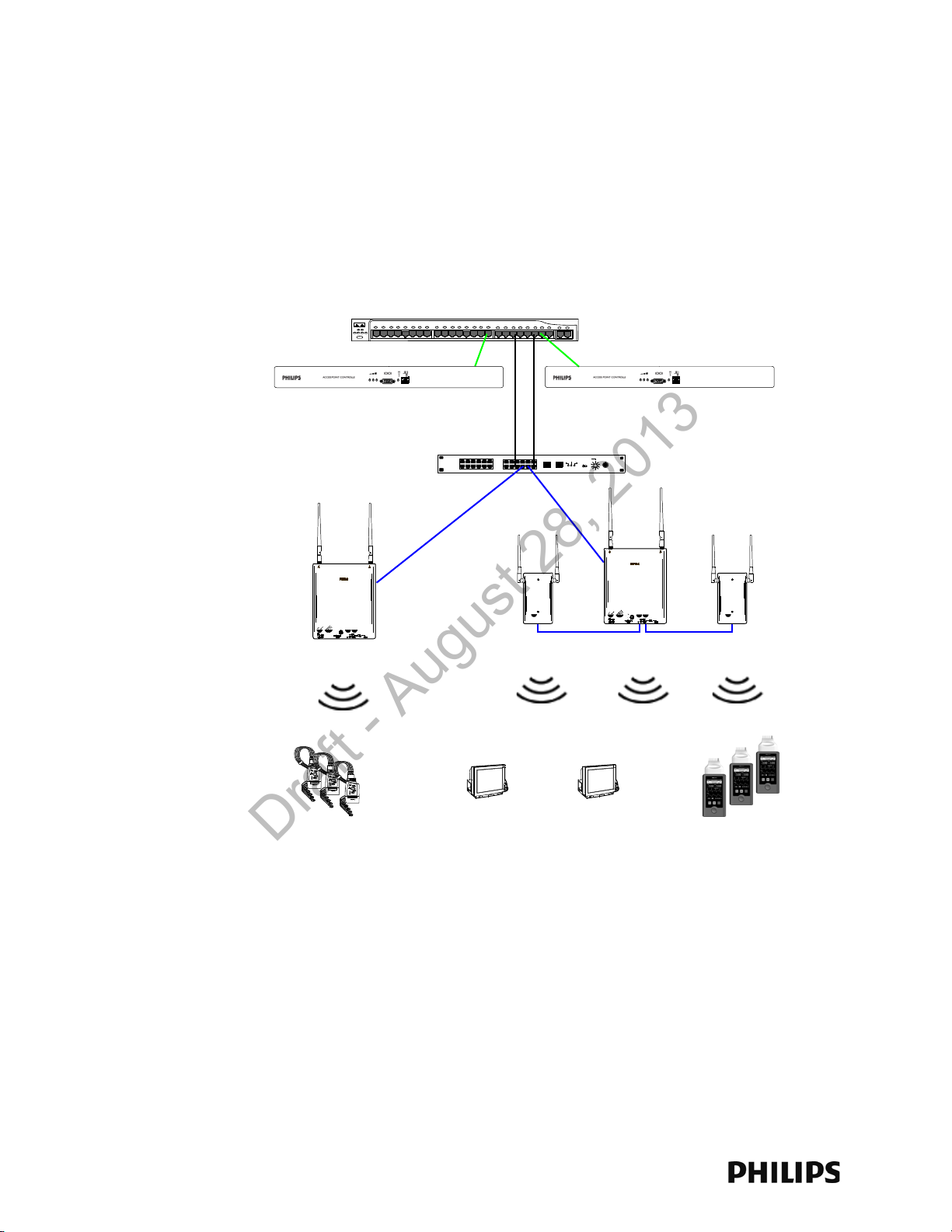
Chapter 1: Overview
Power over Ethernet Switch
Synchronization Unit
1.4 GHz IntelliVue
Smart-hopping
Access Points
Access Point Controller
1.4 GHz
Remote Antenna
1.4 GHz
Core Access Point
Access Point Controller
1.4 GHz
Core Access Point
1.4 GHz
IntelliVue Patient Monitors
Draft - August 28, 2013
Introduction
The IntelliVue Smart-hopping infrastructure uses a cellular wireless architecture to
provide two-way communications between IntelliVue Patient Monitors and the
IntelliVue Information Center.
Using the “IntelliVue Smart-hopping” wireless protocol, the IntelliVue Smart-hopping
infrastructure provides monitoring capabilities for ambulatory patients within a wide
coverage area. The IntelliVue Smart-hopping IntelliVue Patient Monitors and
infrastructure operate on the 1.4 GHz US Wireless Medical Telemetry Service
You can configure the Access Point Controller to communicate with IntelliVue 1.4
GHz IntelliVue Smart-hopping Access Points (APs). IntelliVue 1.4 GHz APs can only
communicate with 1.4 GHz IntelliVue Patient Monitors.
IntelliVue Smart-hopping networks utilize a cognitive radio that senses the RF
environment and adapt to it. Dynamic wireless channel allocation ensures best use
of available wireless spectrum. The IntelliVue Smart-hopping infrastructure is
designed to co-exist with other 802.11 wireless deployments.
Figure 1-1: 1.4 GHz IntelliVue Smart-hopping infrastructure
1-2
Page 13
A General Description of the IntelliVue Smart-hopping Core Access Point
Core AP
Remote
Antenna
Remote
Antenna
74 ft. Coax and
UTP Cable Bundle
Draft - August 28, 2013
A General Description of the IntelliVue Smart-hopping Core Access Point
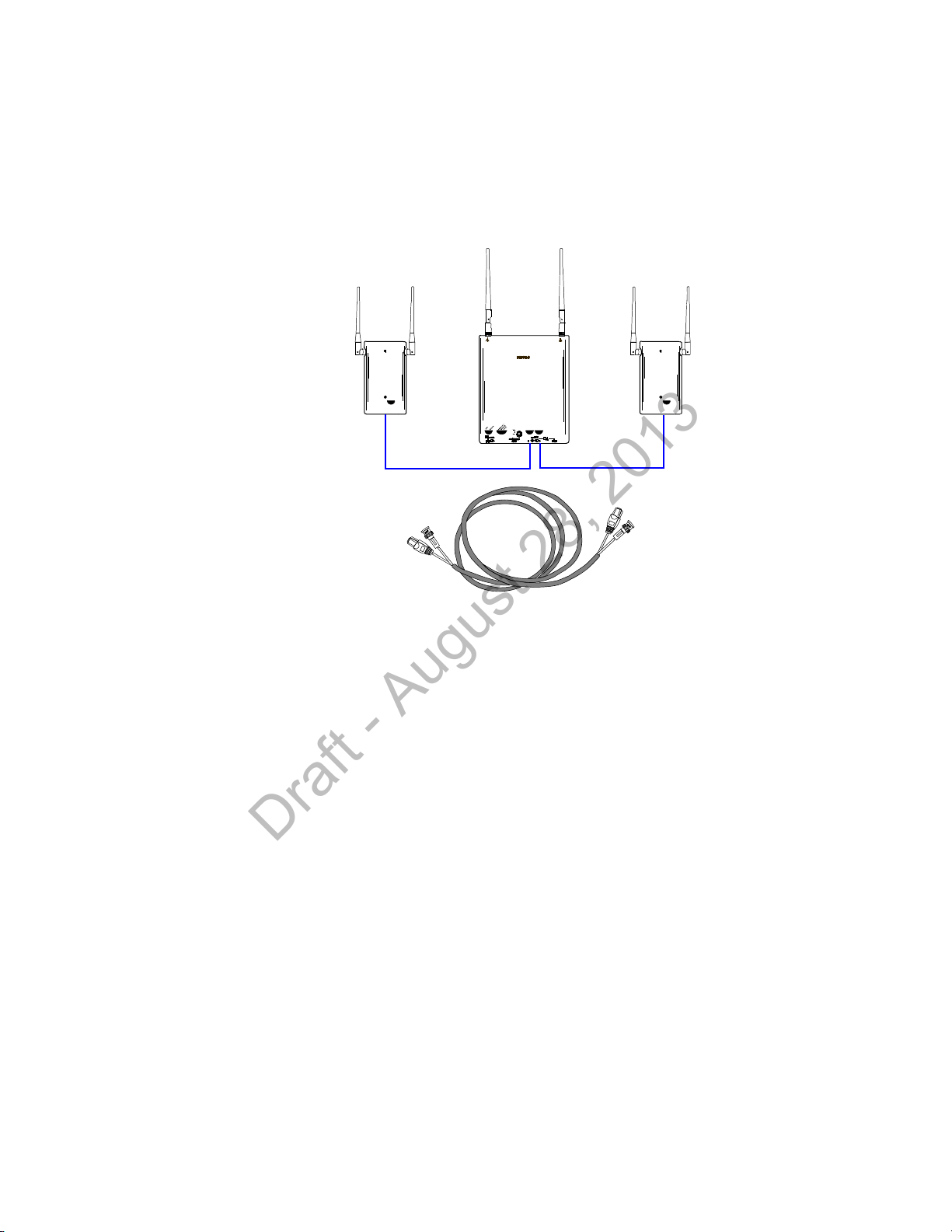
The IntelliVue Smart-hopping Core Access Point (AP), Model ITS4843B (Figure 1-2),
provides an air-link to transmit and receive data between IntelliVue Smart-hopping
IntelliVue Patient Monitors and the Philips IntelliVue Information Center via the
IntelliVue Smart-hopping infrastructure.
Figure 1-2: IntelliVue Smart-hopping Core Access Point
The Core AP is a modular antenna infrastructure consisting of a Core AP (CAP) with
up to two connected Model ITS4846A Remote Antennas (RAs). A 74-foot (22.6 m)
coaxial and unshielded twisted pair (UTP) cable bundle is used to connect a Remote
Antenna to a Core AP. Core APs are only available for the 1.4 GHz IntelliVue Smarthopping infrastructure.
The effective range of the Core AP and of each Remote Antenna is typically 32 feet.
The Core AP always supports a maximum of 18 IntelliVue Patient Monitors
regardless of its component configuration. A Core AP alone supports 18 IntelliVue
Patient Monitors. When used with a single RA, the Core AP supports nine IntelliVue
Patient Monitors and its connected RA supports nine IntelliVue Patient Monitors
(9+9=18). When used with two RAs, the Core AP supports six IntelliVue Patient
Monitors and its connected RAs each support six IntelliVue Patient Monitors
(6+6+6=18).
When monitored patients are ambulatory, data roaming is handled seamlessly
between the other IntelliVue Access Points in the coverage area. The Core AP and
each RA are always used with their two supplied antennas installed. The Core AP
and its attached Remote Antennas can be mounted out of the way on corridor walls,
or above or below ceiling tiles.
IntelliVue Smart-hopping 1.4 GHz High-power Access Point Installation Guide 1-3
Page 14

Chapter 1: Overview
Draft - August 28, 2013
Core AP Mounting Options
Wall-mounting hardware is standard. An optional above/below ceiling tile mount kit
(P/N 862415 Option K05 (453564052201)) is available that can be used with both
the Core AP and its Remote Antennas.
Power Source
The IntelliVue Smart-hopping 1.4 GHz Core Access Point receives its 48 VDC
operating power source via its Ethernet LAN cabling from Power over Ethernet via
the IntelliVue Smart-hopping Sync Unit. The AP is not equipped with a power socket.
The AP consumes less than 13.8W, and internally generates a variety of voltages
used for its internal components.
The CAT-5 UTP cable within the 74 ft.-cable bundle carries 5.5 VDC power, Transmit
and Receive control signals, and Antenna Diversity signals from the Core AP to a
connected Remote Antenna.
The 75 Ohm coaxial cable within the 74 ft.-cable bundle carries RF and DC sense
signals from the Core AP to a connected Remote Antenna.
Synchronization Signal
The IntelliVue Smart-hopping 1.4 GHz Core Access Point receives a synchronization
signal from a network of Sync Units that enables an IntelliVue Patient Monitor to
hand over data seamlessly between APs within the coverage area when a patient is
ambulatory and to transfer data to the IntelliVue Information Center without
interruption. Each Sync Unit provides synchronization for up to 12 APs. The Sync
Unit also distributes the common reference clock signal needed by the IntelliVue
Smart-hopping infrastructure as a whole.
IntelliVue Patient Monitor Mobility
The IntelliVue Smart-hopping infrastructure supports seamless roaming of IntelliVue
Patient Monitors within the area of coverage. This roaming is accomplished via
communications between the IntelliVue Patient Monitors and the Access Points (AP)
as follows.
As an IntelliVue Patient Monitor is moved around a building, it automatically
monitors the quality of the wireless link to its current AP (and it also detects the
presence of other APs). When the quality starts to deteriorate, the IntelliVue Patient
Monitor automatically establishes a new connection to another AP.
The IntelliVue Patient Monitor remains connected to two APs for a finite time, and
thus the same data is received by these APs. During this time, information for
header compression and other data for the connection is routed to the new AP.
One of the two APs subsequently releases the radio connection. If a packet is in
progress when a handover occurs, then the packet is reassembled co-operatively
between the two APs.
The PIIC or PIICix receives an unbroken flow of complete IP packets.
1-4
Page 15

A General Description of the IntelliVue Smart-hopping Core Access Point
Draft - August 28, 2013
Technical Alerts
Each AP is configured to signal alert conditions that are viewed at the IIC in the
wireless status log.
The IntelliVue Access Point is configured to raise alerts on error conditions. The
alerts are sent over the IntelliVue Smart-hopping/ICN Ethernet LAN infrastructure to
a monitoring station or Database Sever. The Access Point raises an alert if:
• if data loss exceeds the configured threshold
• it loses its synchronization signal
For small systems having only one AP and no Sync Unit, the AP can be configured to
suppress the loss of synchronization signal alert.
Note that the IntelliVue Smart-hopping APC provides System Alerts such as loss of
synchronization, high data loss, AP hardware failure, and over capacity. Additionally,
when redundant APCs are installed, the APC will provide a System Alert for APC
hardware or software failure.
Firmware Updates
Firmware on the IntelliVue Smart-hopping 1.4 GHz Core Access Point is upgraded
from the Access Point Controller by using the Upgrade Tool. Refer to the service
document entitled IntelliVue Smart-hopping Infrastructure Installation and Service
Guide for details. The AP firmware image is provided on the Smart-hopping
Telemetry Service Tool CD-ROM.
Management Interfaces
The Access Point supports the full range of management interfaces via the
IntelliVue Smart-hopping Access Point Controller (APC). These interfaces also
enable you to view the status of the Access Point including the following
information:
• System configuration such as firmware version
• Connection information such as numbers of packets received and transmitted,
and number of errors
• Wave data information such as total number of seconds of data sent and lost
The AP statistics can be read by remote devices (e.g., an ICN Database Server),
using the Scaleable Node Address Protocol (SNAP).
The following status items can be displayed using the APC’s web interface:
•AP Name
•Physical Address
• Partnered AP Controller
•IP Address
•Subnet Mask
• Default Gateway
•AP Type
IntelliVue Smart-hopping 1.4 GHz High-power Access Point Installation Guide 1-5
Page 16
Chapter 1: Overview
Ethernet Interface to
IntelliVue Smart-hopping
IntelliVue Smart-
hopping Core Access
IntelliVue Smart-hopping
Remote Antenna
Power/Sync, Radio,
and Network
Status LEDs
Serial Port
UTP Cable Connectors
to Remote Antennas (1 & 2)
with RA Status LEDs
Coaxial Cable Connector
to IntelliVue Smart-hopping
Core Access Point
Coaxial Cable Connectors
to Remote Antennas (1 & 2)
UTP Cable Connector
to IntelliVue Smar t-hopping
Link LED
Activity LED
Connection LED
(Green)
Power LED
(Yellow)
Draft - August 28, 2013
Connectors and Status Indicators
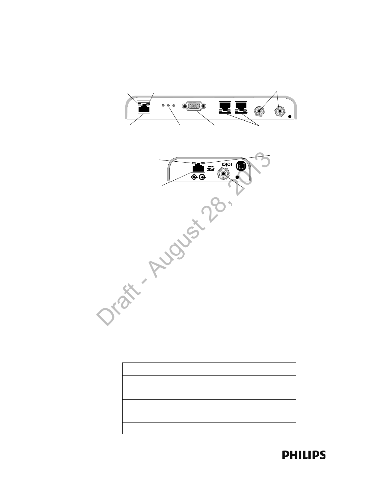
Figure 1-3 shows the controls and connectors on the 1.4 GHz IntelliVue Smarthopping Core AP and Remote Antenna.
Figure 1-3: 1.4 GHz IntelliVue Smart-hopping Core AP and Remote Antenna Controls
and Connectors
IntelliVue Smart-hopping Core AP Connectors
Note the following connectors on the IntelliVue Smart-hopping Core AP:
• Ethernet Interface - The AP provides a 100 Base-T Ethernet interface with an
RJ-45 connector to connect the Core AP to the IntelliVue Smart-hopping Sync
Unit.
The AP Ethernet interface provides data communications to and from the
IntelliVue Information Center over the IntelliVue Smart-hopping LAN
infrastructure. It also presents the 48Vdc power and synchronization signals
required by the Core AP. The synchronization signal is superimposed on the
power supply voltage. Attach the provided ferrite block to the CAT 5 cabling
(from the Sync Unit) no more than 20 inches (50 cm) from the RJ-45 connector
as shown in Figure 2-2 to reduce electromagnetic (radiation) interference.
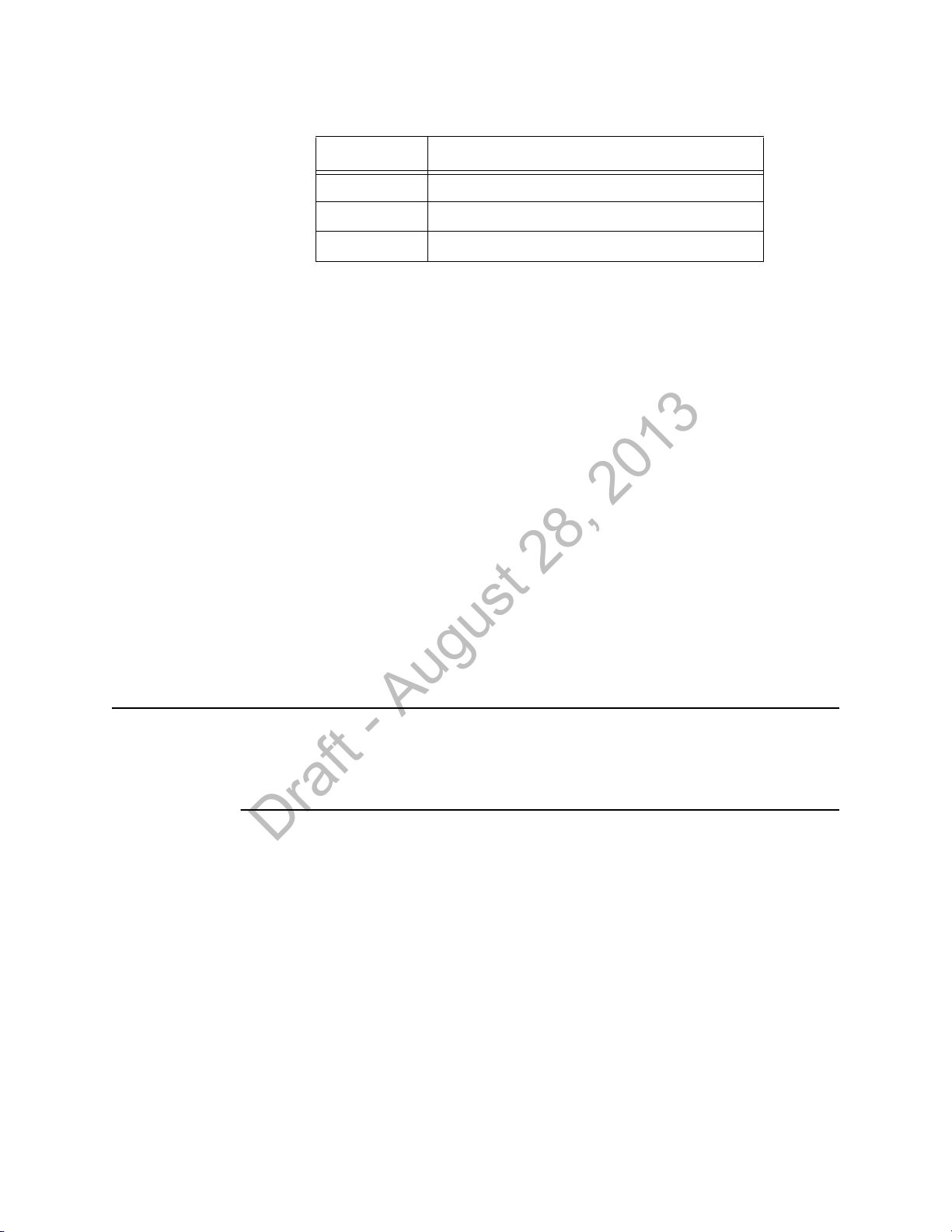
Table 1-1 lists the pin signals for the AP Ethernet interface.
Table 1-1: AP Ethernet Interface Pin Signals
Pin Signal Description
1 Transmit Pair TX + Conductor
2 Transmit Pair TX - Conductor
1-6
3 Receive Pair RX + Conductor
4 + 48Vdc Power and Synchronization
5 + 48Vdc Power and Synchronization
Page 17
Connectors and Status Indicators
Draft - August 28, 2013
Table 1-1: AP Ethernet Interface Pin Signals
Pin Signal Description
6 Receive Pair RX - Conductor
7 0V Power Return
8 0V Power Return
• Serial Port - The serial port is used only for manufacturing purposes.
• UTP Cable Connectors to Remote Antennas - Two standard RJ-45 connectors
are provided for the UTP cables that connect the Core AP to its Remote
Antennas.Each UTP cable carries 5.5 VDC power, Transmit, Receive and
Antenna Diversity Control signals to the Remote Antenna.
• Coaxial Cable Connectors to Remote Antennas - Two standard 75 Ohm
connectors are provided for the coaxial cables that connect the Core AP to its
Remote Antennas. Each coaxial cable carries RF and DC sense signals from the
Remote Antenna.
Remote AP Connectors
Note the following connectors on the Remote Antenna:
• UTP Cable Connector to Core AP - A standard RJ-45 connector is provided for the
UTP cable that connect the Remote Antenna to its Core AP. The UTP cable
carries 5.5 VDC power, Transmit, Receive and Antenna Diversity Control signals
to the Remote Antenna.
• Coaxial Cable Connector to Core AP - A standard 75 Ohm connector is provided
for the coaxial cable that connects the Remote Antenna to its Core AP. The
coaxial cable carries RF and DC sense signals from the Core AP.
Note If an installed, powered Remote Antenna becomes disconnected from its Core AP
via its Coax/UTP cable bundle, you must reconnect the Coax/UTP cable bundle to
the RA and Core AP, and then cycle power to the connected Core AP before the RA
will re-establish communications with the Core AP.
IntelliVue Smart-hopping 1.4 GHz High-power Access Point Installation Guide 1-7
Page 18
Chapter 1: Overview
Draft - August 28, 2013
IntelliVue Smart-hopping Core AP Status LEDs
The IntelliVue Smart-hopping Core AP provides the following status LEDs.
• Wired/Ethernet Activity - The Core AP provides two LEDs to indicate wired/
Ethernet activity to the IntelliVue Smart-hopping infrastructure. During normal
operation, these LEDs indicate the following information:
- Link LED - Link present/Ethernet connection. Lights GREEN (ON) when a
pass-through link is present - OFF when not present.
- Act LED - Wired network activity. Flashes YELLOW (ON) when there is activity
over the wired network.
• Wireless/RF Activity - The Core AP provides three LEDs to indicate wireless/RF
activity. During normal operation, these LEDs indicate the following information:
- Power/Sync LED - GREEN (ON) when power and synchronization signal is
present.
- Radio LED - Normally OFF (not lit) - flashes green to indicate wireless network
activity.
- Network LED - Normally OFF (not lit) - flashes green to indicate wired network
activity.
At initial power on the AP runs a Power On Self-Test (POST). During the POST, the
above LEDs indicators flicker and then all three will illuminate continuously
(AMBER) to indicate correct startup operation. Then, the Power ON LED will
illuminate (GREEN) continuously to indicate that the 48Vdc power and sync
signal are being supplied, and the other two (AMBER) LEDs turn off (not lit).
• Remote Antenna - The Core AP provides two LEDs on each RJ-45 UTP cable
connector that provides status on a connected Remote Antenna:
- RA Connection - Lights GREEN to indicate a RA is connected to the Core AP.
- RA Power - Lights YELLOW to indicate connected RA is receiving power from
the Core AP.
Remote Antenna Status LEDs
The Remote Antenna provides the following status LEDs.
• Remote Antenna Status LEDs - The green and yellow LEDs above the
RJ-45 UTP cable connector to the Core AP provide status on the Remote
Antenna as summarized below.
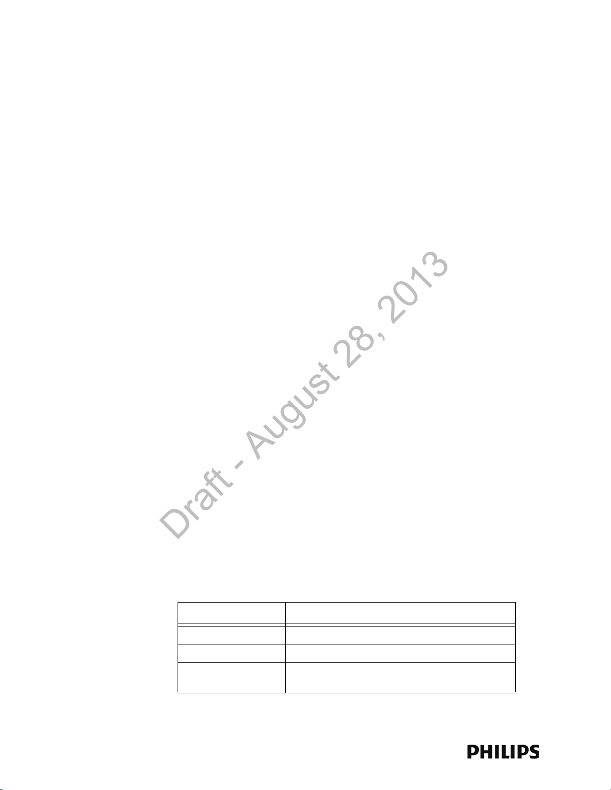
Table 1-2: Remote Antenna Status LEDs
Green/Yellow LEDs Remote Antenna Status
Off/Off No connection to or power from Core AP/Self-test Failed.
Flash Green/Yellow Remote Antenna is running self-test/Power on.
Solid Green/Yellow Connection to Core AP is Successful/Power On.
This is the expected normal operational status.
1-8
Page 19
Specifications
Draft - August 28, 2013
Specifications
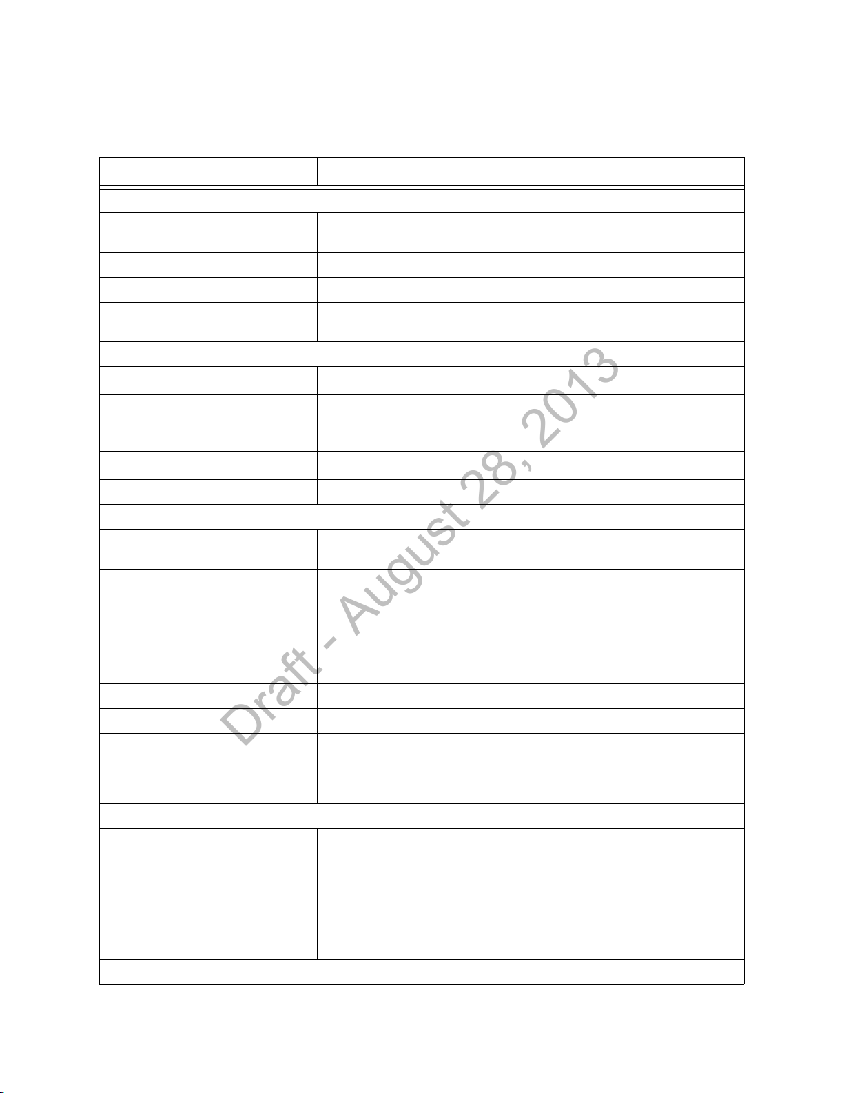
Table 1-3: Model ITS4843B and ITS4843C 1.4 GHz Core Access Point Specifications
Specification Value
Physical:
Chassis (only) Dimensions (H x W x L) 30 mm x 204 mm x 243 mm
(1.2 in x 8.0 in x 9.6 in)
Local Antenna (only) Dimensions 160 mm (6.3 inches L) Sleeve Dipole
Weight with Antenna <.79g (1.8 lb)
Mounting Above Ceiling, Below Ceiling, or Wall Mount, Below Ceiling with quick release, or
Wall Mount with bracket
Environmental:
Operating Temperature
Storage Temperature
Humidity Range (Operating)
Humidity Range (Storage)
0 to +55
-40 to +60
< 95% RH @ 40
< 90% RH @ 60
o
C (32 to 131oF)
o
C (-4 to 140oF)
o
C non-condensing
o
C
Altitude Operating and Storage up to 3048 m (10,000 ft)
Electrical:
Power 48 VDC nominal (44 - 52 VDC), from PoE Unit via Sync Unit) 8 Watts,
287 mA
ITS4843B, RF Power 8.5 dBm +2/-1.5dB (4.5 mW to 11.2 mW) into Antenna load.
ITS4843C, RF Power
(High Power AP)
Power Sensing Auto sensing POE, compliant with 802.3af
RF Diversity Uses Dual Antenna, selects antenna with best signal.
Frequency Diversity Dynamic, selects RF channels for best signals.
Antenna Type Sleeve Dipole > 10dB over 1395MHz to 1432MHz in 50 Ohms.
LED Indicators Two LEDs for LAN activity, part of LAN RJ-45 connector.
Electrical Installation:
Fire Safety Model ITS4843B 1.4 GHz Core Access Points are Listed for use within "Other
12.5 dBm +/-1.5dB (12.6 mW to 25 mW) into Antenna load.
Three LEDs for Radio Activity, Sync, Network status.
Two LEDs on Remote Antenna Ports provide Power and Fault status (part of RA
RJ-45 connector).
Spaces Used for Environmental Air (Plenum)" per NFPA70: 2011, Article
300.22.
Note: The term "plenum" as used in Article 300.22 Section C correlates with the
use of the term "plenum" in NFPA 90A-2009, Standard for the Installation of AirConditioning and Ventilating Systems, and other mechanical codes where the
plenum is used for return air purposes, as well as some other air-handling
spaces. The area above dropped ceilings is an example of plenum space.
Interface Connections:
IntelliVue Smart-hopping 1.4 GHz High-power Access Point Installation Guide 1-9
Page 20
Chapter 1: Overview
Draft - August 28, 2013
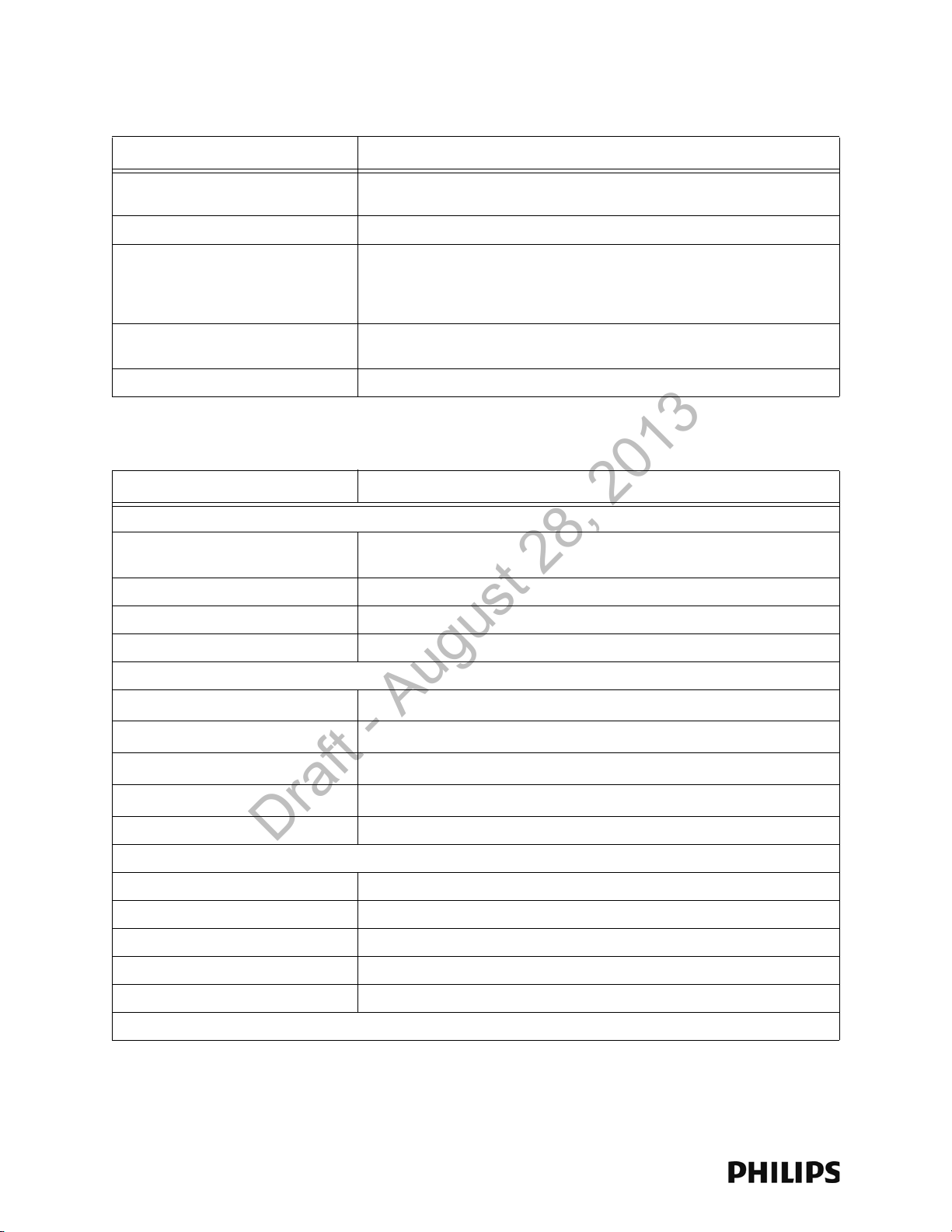
Table 1-3: Model ITS4843B and ITS4843C 1.4 GHz Core Access Point Specifications
Specification Value
LAN Input (Data): 1 Port; Ethernet 100
Base-T (only 100 Mbps Full Duplex)
LAN Cable to Network Switch CAT-5 or better, up to 100m (328 ft.).
Remote Antenna UTP Cable Connectors Two RJ-45 Female Socket Connectors are provided to connect the UTP cables
Remote Antenna 75 Ohm Coaxial Cable
Connectors
Local Antenna Connections (two) Two SMA-style connectors.
RJ-45 Female Socket.
on which 5.5 VDC power, Transmit and Receive control signals, and Antenna
Diversity signals to the remote Antennas are carried. Connectors are protected
against damage from unexpected connection to LAN with PoE
Two standard 75 Ohm connectors are provided for the coaxial cables on which
RF and DC sense signals are carried to the Remote Antenna.
Table 1-4: Model ITS4846A 1.4 GHz Remote Antenna Specifications
Specification Value
Physical:
Chassis (only) Dimensions (H x W x L) 30 mm x 100 mm x 174 mm
(1.2 in x 4.0 in x 6.9 in)
Local Antenna (only) Dimensions 160 mm (6.3 inches L) Sleeve Dipole
Weight with Antenna <.32kg (0.7 lb)
Mounting Above Ceiling, Below Ceiling, or Wall Mount
Environmental:
Operating Temperature
Storage Temperature
Humidity Range (Operating)
Humidity Range (Storage)
Altitude Operating and Storage up to 3048 m (10,000 ft)
Electrical:
Power 5.0 VDC nominal input via Core AP RJ-45 Cable Connector
Power Sensing 802.3af-compliant
RF Diversity Uses Dual Antenna, selects antenna with best signal.
Antenna Type Sleeve Dipole > 10dB over 1395MHz to 1432MHz in 50 Ohms.
LED Indicators Power and Connection LED notification on RJ-45 connector.
Electrical Installation:
0 to +55
-40 to +60
< 95% RH @ 40
< 90% RH @ 60
o
C (32 to 131oF)
o
C (-4 to 140oF)
o
C non-condensing
o
C
1-10
Page 21
Ordering Information
Draft - August 28, 2013
Table 1-4: Model ITS4846A 1.4 GHz Remote Antenna Specifications
Specification Value
Fire Safety Model ITS4846A 1.4 GHz Remote Antennas are Listed for use within "Other
Spaces Used for Environmental Air (Plenum)" per NFPA70: 2011, Article
300.22.
Note: The term "plenum" as used in Article 300.22 Section C correlates with the
use of the term "plenum" in NFPA 90A-2009, Standard for the Installation of AirConditioning and Ventilating Systems, and other mechanical codes where the
plenum is used for return air purposes, as well as some other air-handling
spaces. The area above dropped ceilings is an example of plenum space.
Interface Connections:
Control Signals RJ-45 Female Socket.
Core AP 75 Ohm Coaxial Cable
Connector
Local Antenna Connections (two) Two SMA-style connectors.
One standard 75 Ohm connector is provided for the coaxial cable on which RF
and DC sense signals are carried to the Remote Antenna.
Ordering Information
Table 1-5: IntelliVue Smart-hopping 1.4 GHz Access Point Part Numbers
Device/Option Part Number/Option Number
ITS4843B 1.4 GHz Enhanced IntelliVue Smart-hopping Access Point 989803171211
ITS4843C 1.4 GHz Enhanced IntelliVue Smart-hopping Access Point
(High power AP)
IntelliVue ITS4846A Remote Antenna 865052
IntelliVue Smart-hopping Mounting Options
• Above & Below Ceiling Tile-mount Option for 989803171211 or
865052
989803171211
453564052201 or
862415/K05
IntelliVue Smart-hopping 1.4 GHz High-power Access Point Installation Guide 1-11
Page 22
Chapter 1: Overview
Draft - August 28, 2013
Regulatory Information
Table 1-6: IntelliVue Smart-hopping 1.4 GHz Access Point Regulatory Information
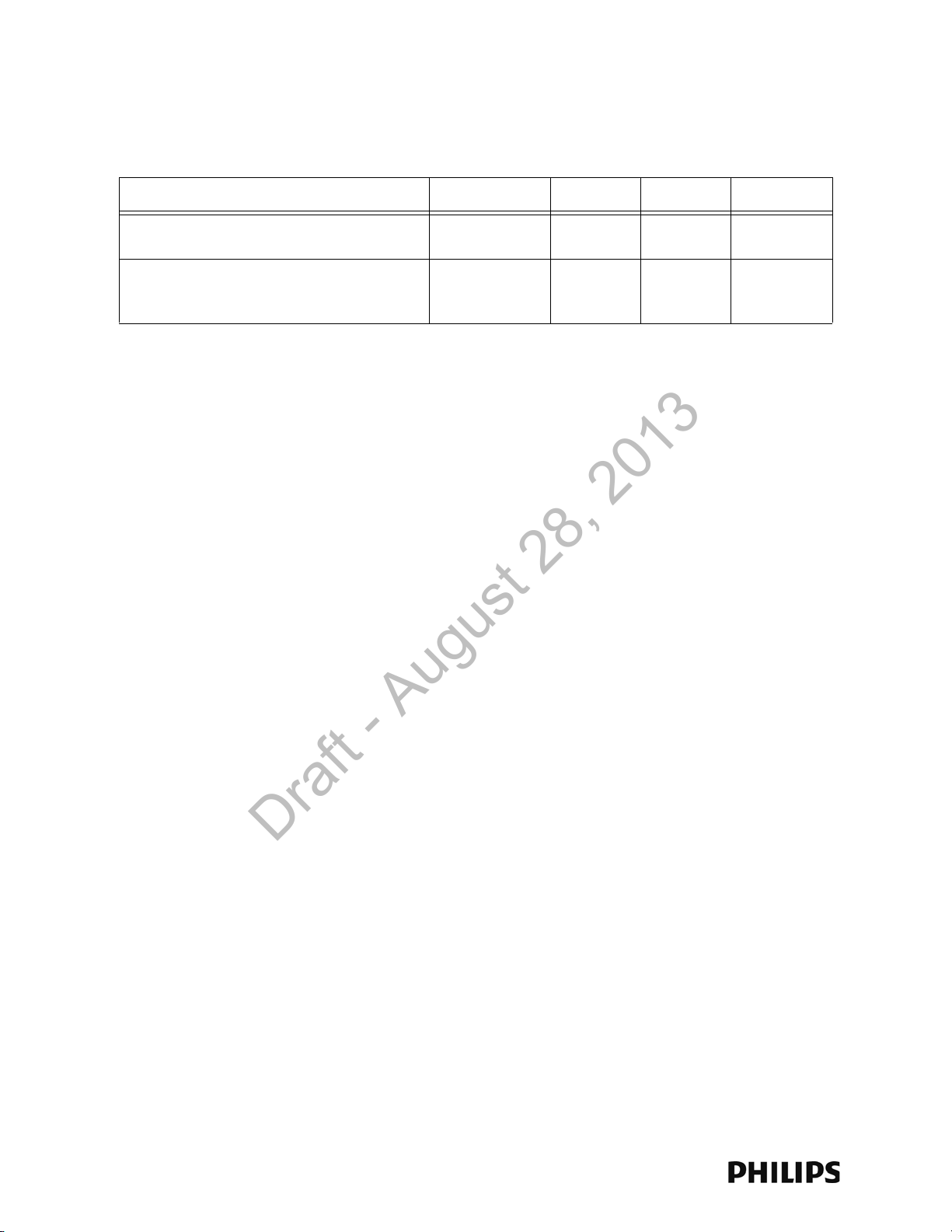
Description Philips part#: FCC ID: Model# Software
1.4 GHz Enhanced IntelliVue Smart-hopping
Access Point
1.4 GHz Enhanced IntelliVue Smart-hopping High
power Access Point
FCC Compliance
Operation of this equipment requires the prior coordination with a frequency
coordinator designated by the FCC for the Wireless Medical Telemetry Service. The
transceiver and the IntelliVue Smart-hopping infrastructure are subject to radio
frequency interference. In the event of suspected radio frequency interference with
your device, contact your service provider. This device complies with Parts 15 and
95H of the Federal Communications Commission (FCC) Rules. Operation is subject
to the condition that this device does not cause harmful interference.
989803171211 PQC-4843B ITS4843B C.00.07
989803171211 PQC-4843C ITS4843C C.00.08 or
greater, or
D.0
1-12
Page 23

2
Installing the IntelliVue Smart-hopping 1.4 GHz Core
Draft - August 28, 2013
Access Point
This chapter provides procedures to physically install the Philips IntelliVue
Smart-hopping 1.4 GHz Core Access Point and includes:
• Access Point Placement Guidelines
• General Installation Procedure
• Mounting the IntelliVue Smart-hopping Core AP to a Wall (Fixed Mount)
• Mounting the IntelliVue Smart-hopping Core AP to a Wall (CA
Earthquake Rated)
• Mounting the IntelliVue Smart-hopping Core AP Above a Ceiling Tile
• Mounting the IntelliVue Smart-hopping Core AP Below a Ceiling Tile
(Fixed Mount)
• Mounting the IntelliVue Smart-hopping Core AP Below a Ceiling Tile
(Quick Release)
• Mounting the IntelliVue Smart-hopping Remote Antenna to a Wall
(Fixed Mount)
• Mounting the IntelliVue Smart-hopping Remote Antenna to a Wall (CA
Earthquake Rated)
• Mounting the IntelliVue Smart-hopping Remote Antenna Above a
Ceiling Tile (Mounting Rails)
• Mounting the IntelliVue Smart-hopping Remote Antenna Above a
Ceiling Tile (Tether Mount)
• Mounting the IntelliVue Smart-hopping Remote Antenna Below a
Ceiling Tile (Fixed Mount)
•Mounting the IntelliVue Smart-hopping RA Below a Ceiling Tile (Quick
Release)
• AP Configuration Information
• Access Point Startup Sequence
IntelliVue Smart-hopping 1.4 GHz High-power Access Point Installation Guide 2-1
Page 24

Chapter 2: Installing the IntelliVue Smart-hopping 1.4 GHz Core Access Point
Draft - August 28, 2013
Access Point Placement Guidelines
Note the following important guidelines when locating IntelliVue Smart-hopping
Access Points:
• Consider building construction when placing APs to account for interference
from ceramic wall tile, lead lined walls, elevator shafts, reinforced windows, and
other obstacles which may cause signal degradation.
• APs should not be placed in locations with more than one wall between the AP
and the coverage area.
• Ensure that the coverage area takes into account bathrooms, hallways, and
windows.
• AP antennas must be more than four inches (10 cm) away from metal
structures. If the antennas are too close to the structure, antenna performance
can be degraded.
• AP antennas must be installed to provide a separation distance of at least eight
inches (20 cm) from all persons and must not be collocated or operating in
conjunction with any other antenna or transmitter.
• A Core AP alone supports 18 IntelliVue Patient Monitors. When used with a
single RA, the Core AP supports nine IntelliVue Patient Monitors and its
connected RA supports nine IntelliVue Patient Monitors (9+9=18). When used
with two RAs, the Core AP supports six IntelliVue Patient Monitors and its
connected RAs each support six IntelliVue Patient Monitors (6+6+6=18).
• If there is a need to support more than 18 IntelliVue Patient Monitors within a
single Radius-of-Coverage cell, Access Points/Remote Antennas can be moved
closer together until the desired density is achieved.
• APs or Remote Antennas shall not be placed closer than three feet (1 m) from
other APs or RAs to prevent signal overload conditions.
• Each IntelliVue Smart-hopping Access Point requires a 100Mbps/Full Duplex
switch port connection.
• Try to avoid placing APs close to other electrical devices (exit lights, light fixtures,
speakers, etc.). Devices like florescent light ballasts can create a significant
amount of interference that can impact system performance.
• Orient the antennas on IntelliVue Smart-hopping APs so that they are
perpendicular to the floor.
2-2
Page 25

General Installation Procedure
Draft - August 28, 2013
To install the IntelliVue Smart-hopping 1.4 GHz Core Access Point:
1. Mount the IntelliVue Smart-hopping 1.4 GHz Core Access Point and Remote
Antennas within the clinic where they can communicate with 1.4 GHz IntelliVue
Patient Monitors. Note these guidelines when installing the IntelliVue Smarthopping Core Access Point and Remote Antennas:
• You may mount each IntelliVue Smart-hopping Core Access Point as follows:
- to a wall (fixed mount) as described on page 2-6
- to a wall (CA earthquake rated) as described on page 2-7
- above a ceiling as described on page 2-9
- below a ceiling (fixed mount) as described on page 2-12
- below a ceiling (quick release) as described on page 2-16
• You may mount each IntelliVue Smart-hopping Remote Antenna as follows:
- to a wall (fixed mount) as described on page 2-21
- to a wall (ca earthquake rated) as described on page 2-23
- above a ceiling as described on page 2-25
- above a ceiling (tether mount) as described on page 2-28
- below a ceiling (fixed mount) as described on page 2-30
- below a ceiling (quick release) as described on page 2-34
General Installation Procedure
• Use category 5 (or better) Unshielded Twisted Pair cable to connect each
IntelliVue Smart-hopping Core Access Point to the IntelliVue Smart-hopping
infrastructure.
• The total length of UTP cable from the IntelliVue Smart-hopping access
point-to the IntelliVue Smart-hopping Synchronization Unit-to the IntelliVue
Smart-hopping Power over Ethernet Unit-to ICN Network Switch cannot
exceed 328 ft. (100 m).
• Use only the supplied, unmodified 74 ft. (22.6m) Coax and UTP cable
bundle when connecting Remote Antennas to the Core AP.
2. Attach each supplied local antenna to the Core AP chassis by inserting the
antenna into the socket connector. Orient the antenna (either straight for wall
mounting or rotate downward for ceiling tile mounting) and then screw on its
collar until the antenna is secure to the chassis.
3. Attach each supplied antenna to the Remote Antenna chassis by inserting the
antenna into the socket connector. Orient the antenna (either straight for wall
mounting or rotate downward for ceiling tile mounting) and then screw on its
collar until the antenna is secure to the chassis.
4. If you have installed Remote Antennas, connect each IntelliVue Smart-hopping
Core Access Point to its installed Remote Antenna(s) using the supplied,
unmodified 74 ft. (22.6m) Coax and UTP cable bundle(s).
IntelliVue Smart-hopping 1.4 GHz High-power Access Point Installation Guide 2-3
Page 26
Chapter 2: Installing the IntelliVue Smart-hopping 1.4 GHz Core Access Point
Ethernet Interface to
IntelliVue Smart-hopping
IntelliVue Smart-
hopping Core Access
IntelliVue Smart-hopping
Remote Antenna
Power/Sync, Radio,
and Network
Status LEDs
Serial Port
UTP Cable Connectors
to Remote Antennas (2 & 1)
with RA Status LEDs
Coaxial Cable Connector
to IntelliVue Smart-hopping
Core Access Point
Coaxial Cable Connectors
to Remote Antennas (2 & 1)
UTP Cable Connector
to IntelliVue Smar t-hopping
Link LED
Activity LED
Connection LED
(Green)
Power LED
(Yellow)
RA 2 RA 1
RA 2 RA 1
Draft - August 28, 2013
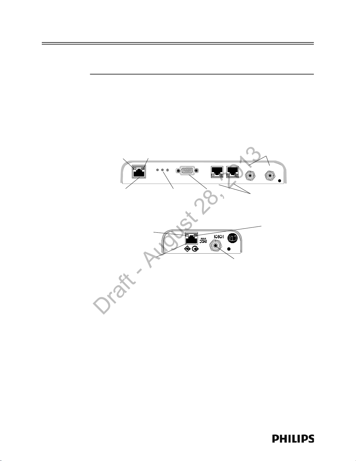
Caution Do not kink the RA Coax-and-UTP-cable-bundle during installation. You must
maintain a minimum 2.5-inch (64-mm) bend radius for the RA Coax-and-UTP-cablebundle throughout the installation.
a) Connect the first Remote Antenna to the Core AP using the UTP and Coaxial
cable connectors labeled RA 1 in Figure 2-1.
b) Connect the second Remote Antenna to the Core AP using the UTP and
Coaxial cable connectors labeled RA 2 in Figure 2-1.
c) Be sure to label the UTP cable bundles and the Remote Antennas
themselves as RA 1 and RA 2 corresponding to the cable connections you
made in steps a and b.
Figure 2-1: 1.4 GHz IntelliVue Smart-hopping Core AP and Remote Antenna Controls
5. Route a Category 5 UTP cable between each IntelliVue Smart-hopping Core
Access Point and the equipment closet in which the IntelliVue Smart-hopping
infrastructure devices are installed.
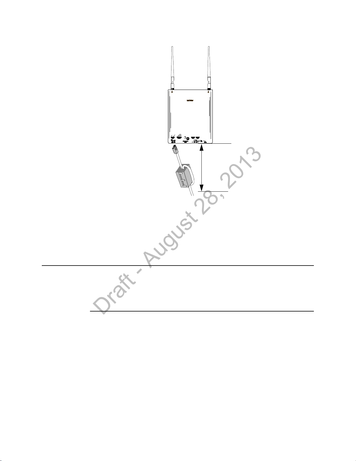
6. Install a ferrite block on the UTP cable within 20 inches (50 cm) of the RJ-45
2-4
connector that connects to the Core Access Point as shown in Figure 2-2.
and Connectors
Page 27
General Installation Procedure
Distance = less than
20 inches (50cm)
Draft - August 28, 2013
Figure 2-2: Installing a Ferrite Block on the UTP Cable to the IntelliVue Smart-hopping
Infrastructure
7. Connect the Access Point to the IntelliVue Smart-hopping Sync Unit only when
appropriate as part of the overall IntelliVue Smart-hopping installation.
a) After initially connecting and powering the Core AP, verify that the two status
LEDs on each of its connected Remote Antennas are lit. You can verify this
by viewing the AP’s Status page presented in the APC web interface.
Note If after connecting and powering the Core AP, its LEDs are lit red and the Remote
Antenna LEDs do not light at all, open the APC web interface, click System in the
View Device tree, click Configure and then select the Advanced tab. Verify that the
Allow new APs to be added automatically option is set to True. This option must be
set to True for the Core AP and Remote Antenna LEDs to light properly.
b) Reboot the Core AP.
The Core AP and its connected Remote Antennas should now be listed in the
APC web interface. Press F5 to refresh the web interface display if the Core
AP and RAs are not listed.
General AP configuration information is given on page 2-37. See page 2-37 for the
AP startup sequence.
IntelliVue Smart-hopping 1.4 GHz High-power Access Point Installation Guide 2-5
Page 28
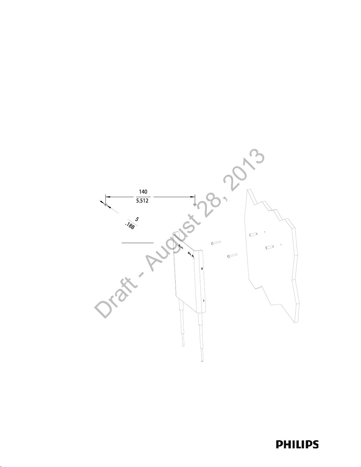
Chapter 2: Installing the IntelliVue Smart-hopping 1.4 GHz Core Access Point
Units: millimeters
inches
Draft - August 28, 2013
Mounting the IntelliVue Smart-hopping Core AP to a Wall (Fixed Mount)
You can mount the IntelliVue Smart-hopping Core Access Point to a wall using the
mounting screws and screw anchors supplied with the AP. We recommend that you
mount the Core AP high on the wall as close to the ceiling as possible.
To mount the 1.4 GHz IntelliVue Smart-hopping Core AP to a wall:
1. Using a 3/16-inch drill bit, drill a pilot hole 0.188 inches (5 mm) in diameter at
the locations shown in Figure 2-3.
2. Tap a supplied plastic screw anchor into each pilot hole until it is flush with the
wall surface.
This step is not necessary if mounting the IntelliVue Smart-hopping Core AP on a
wood surface.
3. Screw a supplied #6 x 1 1/4 inch self-tapping screw into each screw anchor (or
pilot hole) as shown in Figure 2-3.
Tighten each screw until a 1/16-inch (2 mm) gap remains between the screw
head and the mounting surface.
Figure 2-3: Mounting the IntelliVue Smart-hopping 1.4 GHz Core AP to a Wall (Fixed
4. While holding the AP chassis with its antennas pointing down as shown in
Figure 2-3, fit the holes in the back of the AP chassis over the screw heads that
protrude from the wall. Slide the AP chassis down so that the screw heads are
securely in the grooves in the back of the AP chassis.
2-6
Mount)
Page 29
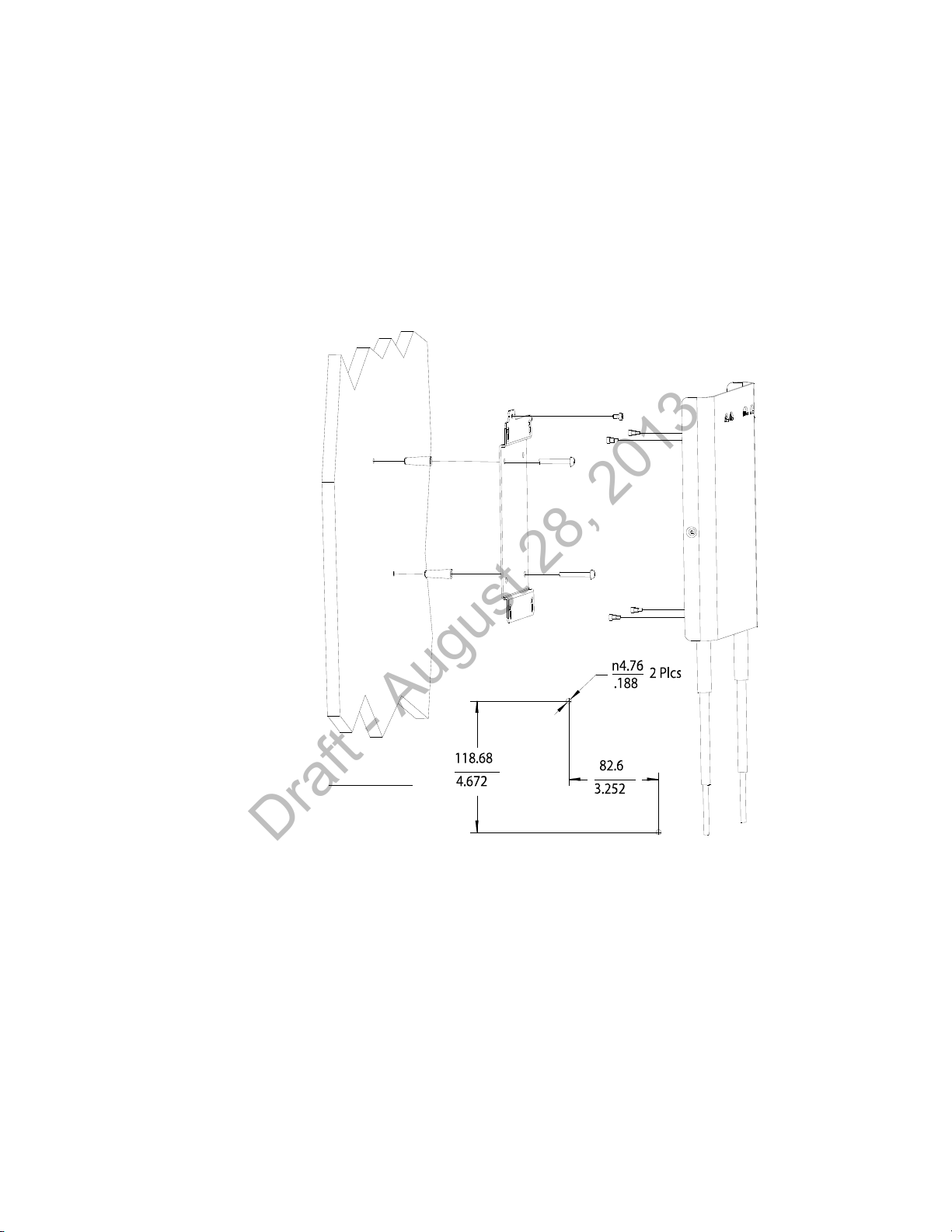
Mounting the IntelliVue Smart-hopping Core AP to a Wall (CA Earthquake Rated)
Units: millimeters
inches
Draft - August 28, 2013
Mounting the IntelliVue Smart-hopping Core AP to a Wall (CA Earthquake
Rated)
You can mount the IntelliVue Smart-hopping Core Access Point onto walls using an
optional California (CA) earthquake-rated wall plate. We recommend that you mount
the Core AP high on the wall as close to the ceiling as possible.
To mount the 1.4 GHz IntelliVue Smart-hopping Core AP to a wall:
1. Using a 3/16-inch drill bit, drill two pilot holes 0.188 inches (5 mm) in diameter
at the locations shown in Figure 2-4.
Figure 2-4: Mounting the IntelliVue Smart-hopping 1.4 GHz Core AP to a Wall (CA
Earthquake Rated)
2. Tap a supplied plastic screw anchor into each pilot hole until flush with the wall
surface.
This step is not necessary if mounting the IntelliVue Smart-hopping Core AP on a
wood surface.
3. Secure the quick release wall plate to the wall by screwing a supplied #6 x 1
1/4 inch self-tapping screw through the wall plate into each screw anchor (or
pilot hole) as shown in Figure 2-4.
Tighten each screw until the wall plate is fixed securely in place.
IntelliVue Smart-hopping 1.4 GHz High-power Access Point Installation Guide 2-7
Page 30
Chapter 2: Installing the IntelliVue Smart-hopping 1.4 GHz Core Access Point
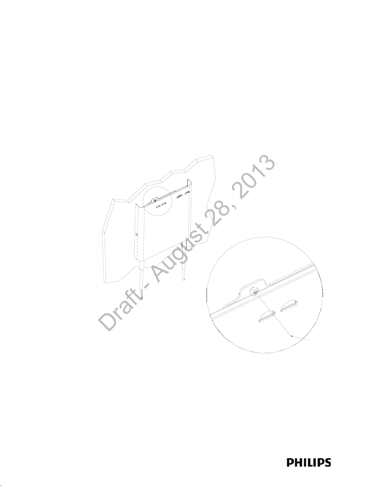
Insert M3.5 Security Screw
through this View Port and
Tighten Using a Torx T10
Screwdriver.
Draft - August 28, 2013
4. Using a 5/64-inch (2 mm) Allen (i.e., hexagonal) wrench, secure the four
supplied M3 X 0.5 hex-head shoulder screws to the back of the Core AP as
shown in Figure 2-4. Torque-tighten each shoulder screw to 8-inch lbs.
5. Mount the Core AP to the wall plate by inserting the head of each shoulder
screw into the four mounting holes provided in the wall plate and then sliding
the Core AP down so that the shoulder screw heads are securely in the grooves
of the wall plate.
6. Using a Torx T10 screw driver, secure the Core AP to the wall plate by screwing
the supplied M3.5 X 0.6 T-10 Torx Head security screw into the PEM nut in the
wall plate as shown in Figure 2-5. Torque-tighten the screw to 10-inch lbs. Note
that this safety screw is used to prevent the Core AP from sliding out of the wall
plate.
Figure 2-5: Securing the Core AP to its Quick Release Wall Plate
2-8
Page 31

Mounting the IntelliVue Smart-hopping Core AP Above a Ceiling Tile
Draft - August 28, 2013
Mounting the IntelliVue Smart-hopping Core AP Above a Ceiling Tile
You can mount the IntelliVue Smart-hopping Core Access Point above a ceiling tile
by using the mounting rails provided in the Above & Below Ceiling Tile Mount Kit
(862415-K05) for the Core AP and Remote Antennas.
Caution When installing the IntelliVue Access Point onto a suspended ceiling, make certain
the ceiling grid is structurally rated to support the weight of the Core Access Point,
0.79 kg (1.8 lbs), and any extra cabling.
To mount the 1.4 GHz IntelliVue Smart-hopping Core AP above a ceiling tile:
1. Determine which ceiling tile the Core AP is be mounted onto, and the
approximate Core AP placement and orientation of the antennas on the tile.
Also, check for adequate clearance above the Core AP.
2. Remove the ceiling tile to which the Core AP will be mounted (and also an
adjacent tile to facilitate installation).
3. Orient the antenna(s) on the Core AP chassis so they bend downward at right
angles to the chassis. Unscrew the collar and rotate the antenna into position
and then retighten the collar to secure the antenna in place.
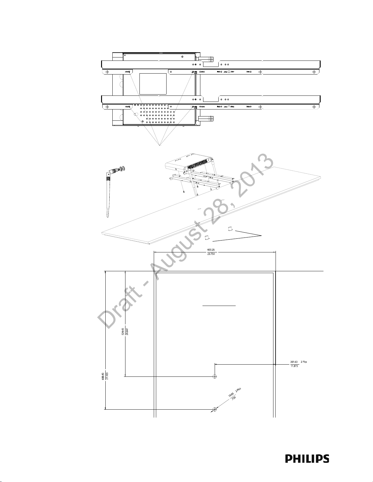
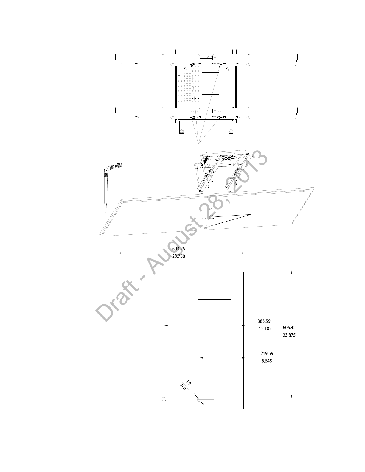
4. Determine where the two holes for the antennas are going to be located on the
tile and mark the centers of the holes.
The Core AP chassis can be rotated 90 degrees to the mounting rails. Choose
the best placement of the Core AP to facilitate where the antennas will go
through the ceiling tile. Note that there are additional holes in the mounting
rails to allow for tethering to other permanent structures where local building
codes require this type of installation. Refer to Figure 2-6 or Figure 2-7 for the
dimensions used to locate the antenna holes in the tile.
5. Drill out two 3/4-inch (19 mm) diameter holes in the ceiling tile for the
antennas. Lightly coat both plastic grommets with silicone adhesive and insert
them into both holes in the tile (Insert grommets from the outside of the tile).
6. Secure the mounting rails to the AP. Insert the four (4) M3 x 0.5 (8 mm LG)
screws into the Core AP mounting rail holes, and into the mating holes in the
back of the Core AP as shown in Figure 2-6 or Figure 2-7. Torque-tighten each
shoulder screw to 8-inch lbs.
7. Place the Core AP with mounting rails across the top of the tile.
8. Replace the tile back onto the ceiling frame structure with the Core AP antennas
hanging down through the ceiling. Wiring connections to the Core AP can be
accessed via the open adjacent tile.
9. Replace other adjacent ceiling tiles if necessary.
IntelliVue Smart-hopping 1.4 GHz High-power Access Point Installation Guide 2-9
Page 32
Chapter 2: Installing the IntelliVue Smart-hopping 1.4 GHz Core Access Point
Use These Holes Marked AM2
Grommets
Bend Down
Tighten Collar
Units: millimeters
inches
Draft - August 28, 2013
Figure 2-6: Possible Above the Ceiling Core AP Mounting Position
2-10
Page 33
Mounting the IntelliVue Smart-hopping Core AP Above a Ceiling Tile
Use These Holes Marked AM4
Grommets
Bend Down
Tighten Collar
Units: millimeters
inches
Draft - August 28, 2013
Figure 2-7: Alternative Above the Ceiling Core AP Mounting Position
IntelliVue Smart-hopping 1.4 GHz High-power Access Point Installation Guide 2-11
Page 34

Chapter 2: Installing the IntelliVue Smart-hopping 1.4 GHz Core Access Point
Draft - August 28, 2013
Mounting the IntelliVue Smart-hopping Core AP Below a Ceiling Tile (Fixed Mount)
You can mount the IntelliVue Smart-hopping Access Point below a ceiling tile by
using the mounting rails provided in the Above & Below Ceiling Tile Mount Kit
(862415-K05) for the Core AP and Remote Antennas.
Caution When installing the IntelliVue Access Point onto a suspended ceiling, make certain
the ceiling grid is structurally rated to support the weight of the Access Point, 0.7kg
(1.5 lbs), and any extra cabling.
To mount the 1.4 GHz IntelliVue Smart-hopping Core AP below a ceiling tile:
1. Determine which ceiling tile the Core AP is be mounted onto, and the
approximate placement of the Core AP and orientation of the antennas hanging
down from the ceiling tile.
2. Remove the ceiling tile the Core AP will be mounted to (and also the adjacent
tile to facilitate installation).
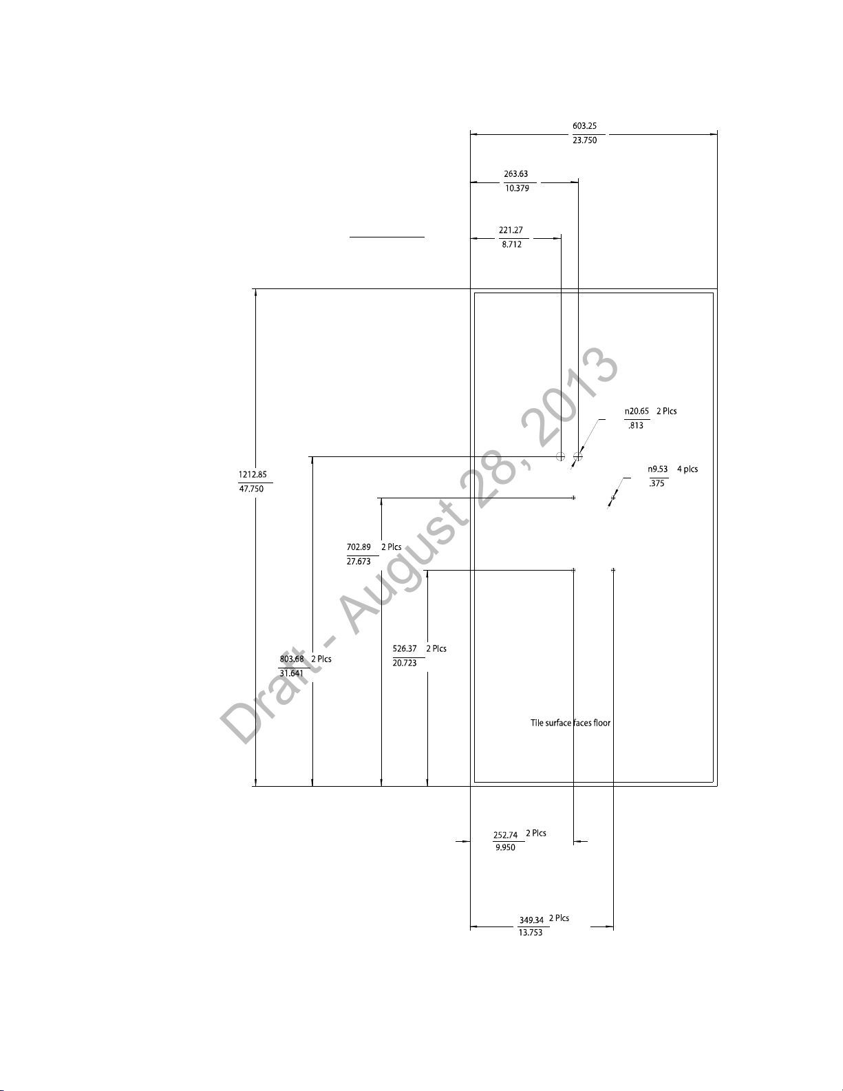
3. Refer to Figure 2-8 for all dimensions and hole locations. Place the mounting
rails across the tile (underside of tile). For ceiling tiles that are smaller than
standard 2’ x 4’ size ceiling tile, the mounting rails can be cut down in length at
the u-shaped cutouts.
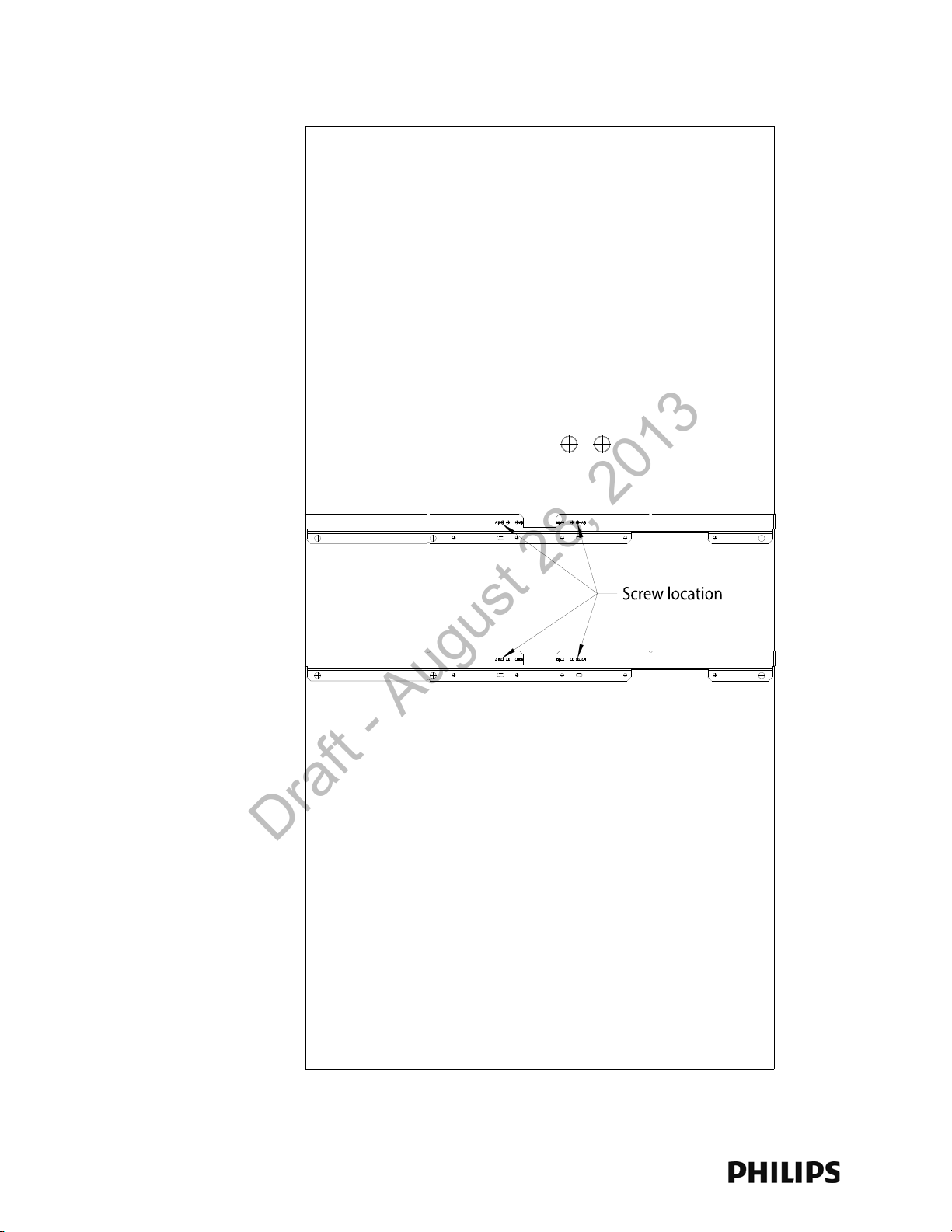
4. Mark the location of the AB screw holes in the mounting rails on the ceiling tile
where the holes will be drilled through the tile as shown in Figure 2-9. Drill four
.375-inch (10 mm) diameter holes in the ceiling tile.
5. Determine where the two holes for the Remote Antenna cables are going to be
located on the tile and mark the centers of the hole.
Note that one of these holes will also be used to route the CAT 5 cable that
connects the Core AP to the Sync Unit on the IntelliVue Smart-hopping
infrastructure.
6. Drill or cut out two .813-inch (21 mm) diameter holes for the Remote Antenna
cables to be connected to the Core AP. Lightly coat a plastic grommet with
silicone adhesive and insert it into each hole in the tile (insert grommet from the
outside of the tile).
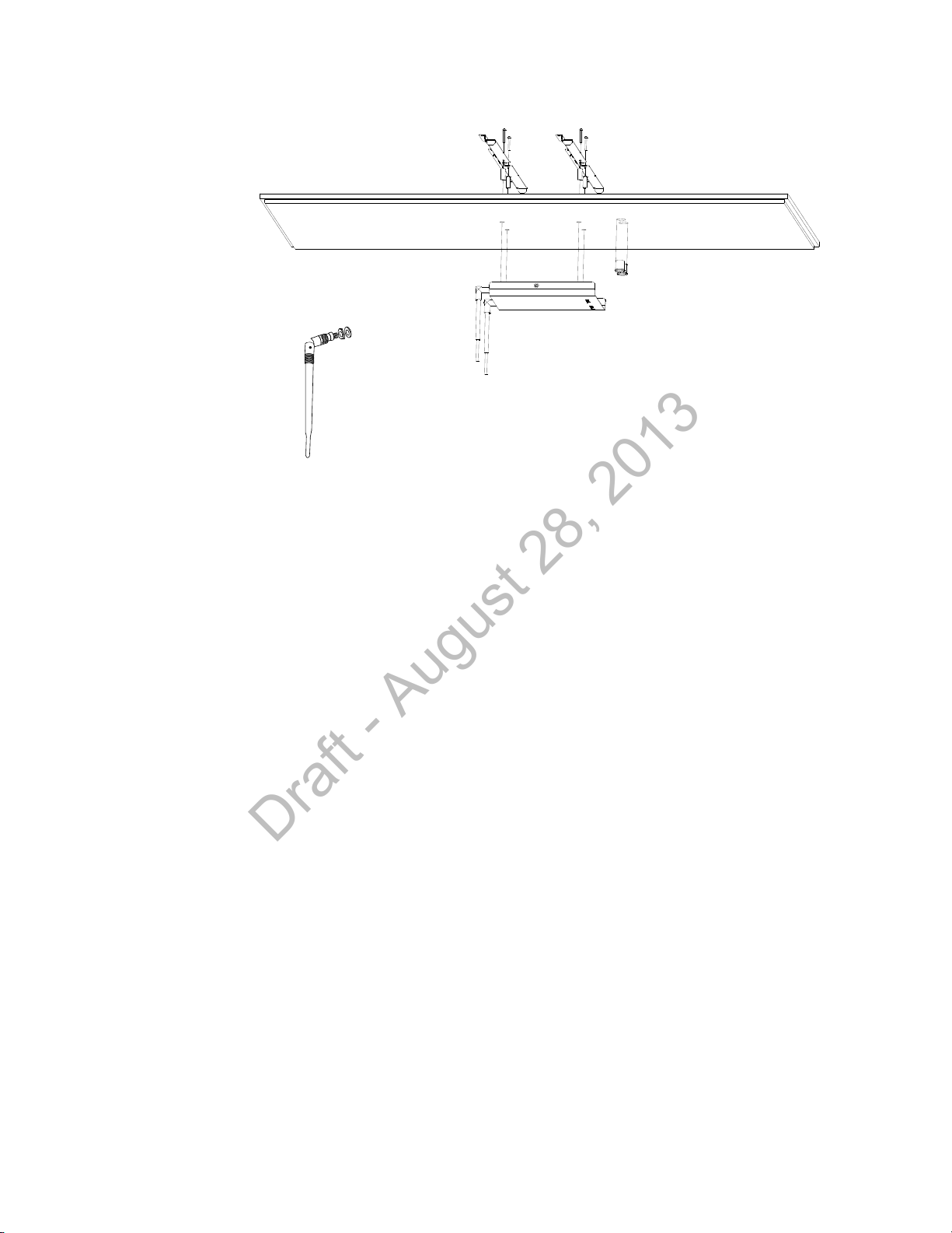
7. Insert the four (4) M3-.5 X 30 lobe screws into the Core AP mounting rail holes,
through the provided plastic spacers, through the tile, and into the mating holes
in the back of the Core AP as shown in Figure 2-10. Torque-tighten each screw
to 8-inch lbs.
Note that the Core AP mounting rails and spacers allow for sufficient airflow
between the Core AP and the ceiling tile.
8. Orient the antenna(s) on the Core AP chassis so they bend upward at right
angles to the chassis. Unscrew the collar and rotate into position and then
retighten the collar to secure the antenna in place.
9. Replace the tile back onto the ceiling frame structure with the Core AP antennas
hanging down from the ceiling. Cabling connections to the Core AP can be
accessed via the open holes in the tile.
2-12
Page 35
Units: millimeters
inches
Draft - August 28, 2013
Mounting the IntelliVue Smart-hopping Core AP Below a Ceiling Tile (Fixed Mount)
Figure 2-8: Core AP Below Ceiling Tile Hole Locations and Dimensions
IntelliVue Smart-hopping 1.4 GHz High-power Access Point Installation Guide 2-13
Page 36
Chapter 2: Installing the IntelliVue Smart-hopping 1.4 GHz Core Access Point
Use the Screw Locations
Marked AB
Draft - August 28, 2013
Figure 2-9: Core AP Below Ceiling Tile Mounting Rail Screw Locations
2-14
Page 37
Mounting the IntelliVue Smart-hopping Core AP Below a Ceiling Tile (Fixed Mount)
Bend Down
Tighten Collar
Draft - August 28, 2013
Figure 2-10: Mounting the Core AP Below a Ceiling Tile (Fixed Mount)
Note that there are additional holes in the mounting rails to allow for tethering
to other permanent structures where local building codes require this type of
installation.
10. Replace other adjacent ceiling tiles if necessary.
IntelliVue Smart-hopping 1.4 GHz High-power Access Point Installation Guide 2-15
Page 38
Chapter 2: Installing the IntelliVue Smart-hopping 1.4 GHz Core Access Point
Draft - August 28, 2013
Mounting the IntelliVue Smart-hopping Core AP Below a Ceiling Tile (Quick Release)
You can mount the IntelliVue Smart-hopping Access Point below a ceiling tile by
using an optional quick release wall plate along with the mounting rails provided in
the Above & Below Ceiling Tile Mount Kit for the Core AP and Remote Antennas
(862415-K05). Use of this wall plate enables you to relocate 1.4 GHz IntelliVue
Smart-hopping Core APs within your facility quickly and easily.
Caution When installing the IntelliVue Access Point onto a suspended ceiling, make certain
the ceiling grid is structurally rated to support the weight of the Access Point, 0.7kg
(1.5 lbs), and any extra cabling.
To mount the 1.4 GHz IntelliVue Smart-hopping Core AP below a ceiling tile:
1. Determine which ceiling tile the Core AP is be mounted onto, and the
approximate placement of the Core AP and orientation of the antennas hanging
down from the ceiling tile.
2. Remove the ceiling tile to which the Core AP will be mounted (and also the
adjacent tile to facilitate installation).
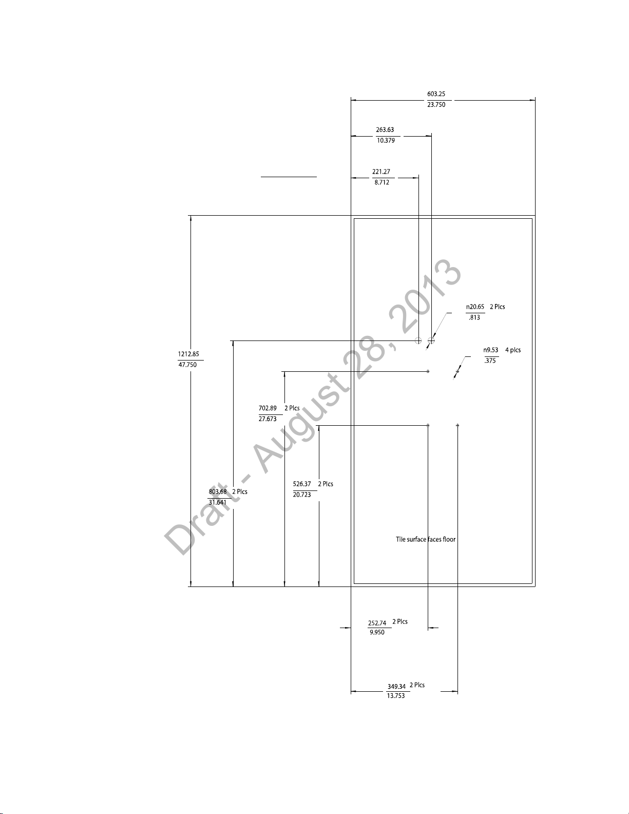
3. Refer to Figure 2-11 for all dimensions and hole locations. Place the mounting
rails across the tile (underside of tile). For ceiling tiles that are smaller than
standard 2’ x 4’ size ceiling tile, the mounting rails can be cut down in length at
the u-shaped cutouts.
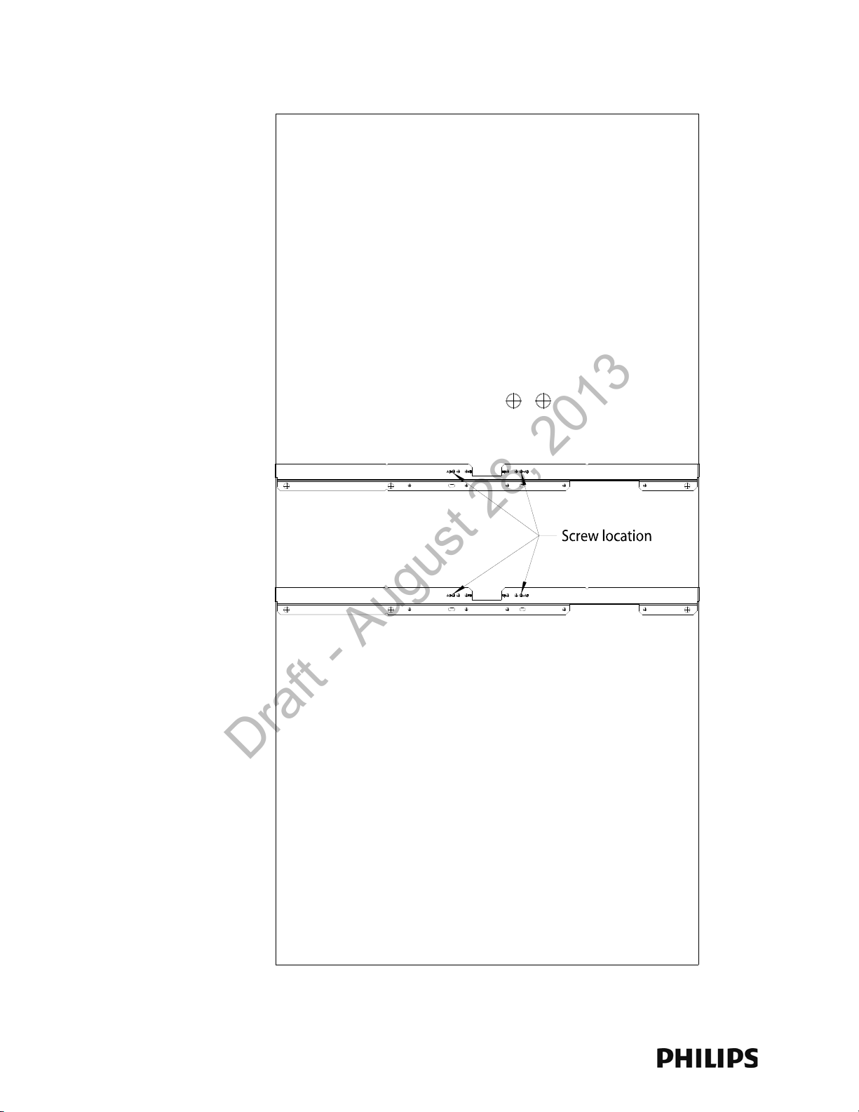
4. Mark the location of the AB screw holes in the mounting rails on the ceiling tile
where the holes will be drilled through the tile as shown in Figure 2-12. Drill four
.375-inch (10 mm) diameter holes in the ceiling tile.
5. Determine where the two holes for the Remote Antenna cabling are going to be
located on the tile and mark the centers of the hole.
Note that one of these holes will also be used to route the CAT 5 cable that
connects the Core AP to the Sync Unit on the IntelliVue Smart-hopping
infrastructure.
6. Drill or cut out two .813-inch (21 mm) diameter holes for the Remote Antenna
cables to be connected to the Core AP. Lightly coat a plastic grommet with
silicone adhesive and insert it into each hole in the tile (insert grommet from the
outside of the tile).
7. Place the AP wall plate over the four holes drilled on the bottom of the tile. Note:
The top of the tile is the side facing up when the tile is in its installed position.
8. Insert the four (4) M3 .5 x 0.6 x 30mm screws into the AP wall plate, through the
tile, and into the mating holes in the mounting rails on top of the tile. Hand
tighten the four locking hex nuts onto the screws, and then torque-tighten each
nut to 10-inch lbs (#1 Pozidrive).
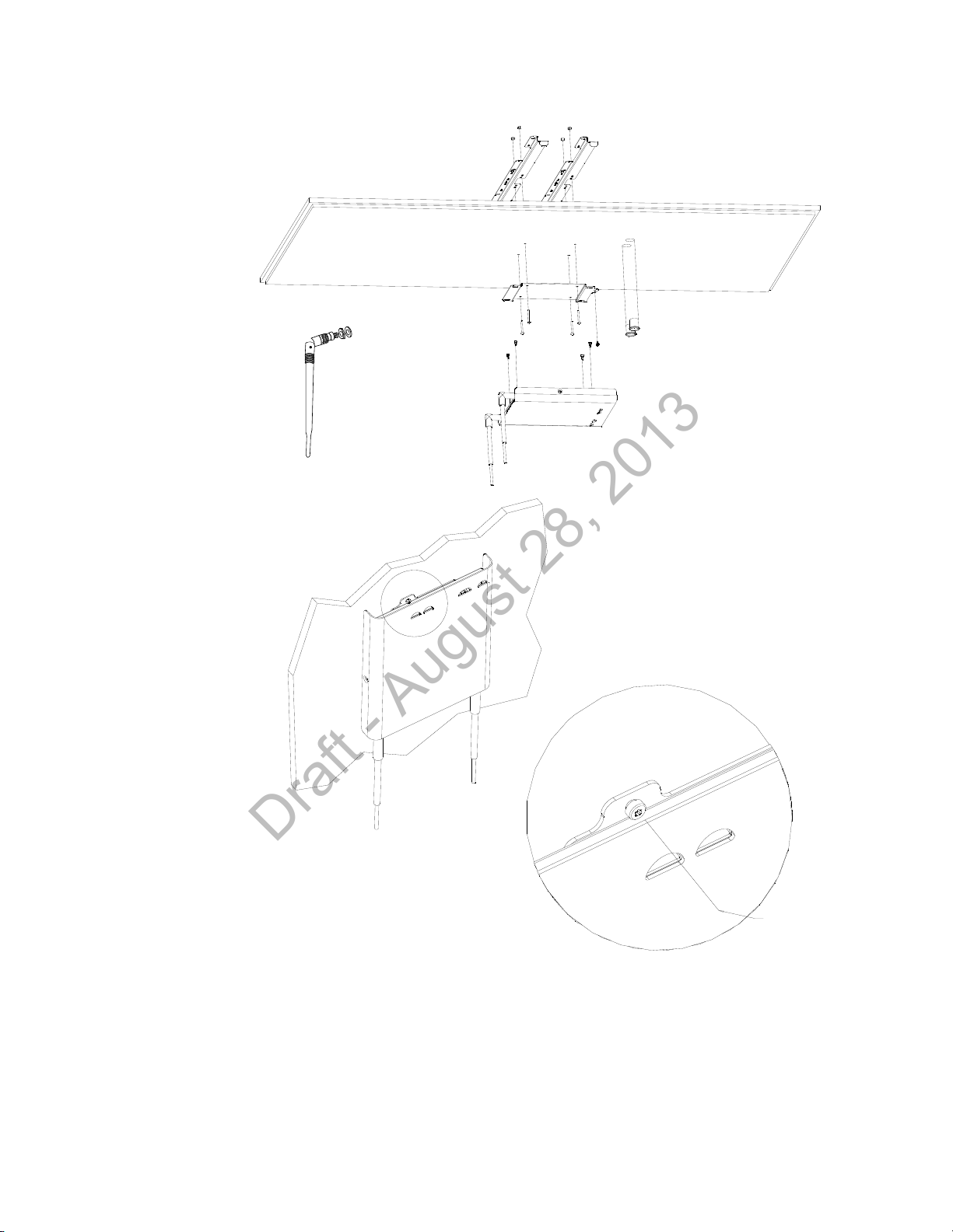
9. Using a 5/64-inch (2 mm) Allen (i.e., hexagonal) wrench, secure the four
supplied M3 X 0.5 hex-head shoulder screws to the back of the Core AP as
shown in Figure 2-13. Torque-tighten each shoulder screw to 8-inch lbs.
2-16
Page 39
Units: millimeters
inches
Draft - August 28, 2013
Mounting the IntelliVue Smart-hopping Core AP Below a Ceiling Tile (Quick Release)
Figure 2-11: Core AP Below Ceiling Tile Hole Locations and Dimensions
IntelliVue Smart-hopping 1.4 GHz High-power Access Point Installation Guide 2-17
Page 40
Chapter 2: Installing the IntelliVue Smart-hopping 1.4 GHz Core Access Point
Use the Screw Locations
Marked AB
Draft - August 28, 2013
Figure 2-12: Core AP Below Ceiling Tile Mounting Rail Screw Locations
2-18
Page 41
Mounting the IntelliVue Smart-hopping Core AP Below a Ceiling Tile (Quick Release)
Bend Down
Tighten Collar
Insert M3.5 Security Screw
through this View Port and
Tighten Using a Torx T10
Screwdriver.
Draft - August 28, 2013
Figure 2-13: Mounting the Core AP Below a Ceiling Tile (Quick Release
10. Mount the Core AP to the wall plate by inserting the head of each shoulder
screw into the four mounting holes provided in the wall plate and then sliding
IntelliVue Smart-hopping 1.4 GHz High-power Access Point Installation Guide 2-19
Page 42

Chapter 2: Installing the IntelliVue Smart-hopping 1.4 GHz Core Access Point
Draft - August 28, 2013
the Core AP so that the shoulder screw heads are securely in the grooves of the
wall plate.
11. Using a Torx T10 screw driver, secure the Core AP to the wall plate by screwing
the supplied M3 0.5 X 0.6 T-10 Torx Head security screw into the PEM nut in the
wall plate as shown in Figure 2-13. Torque-tighten the screw to 10-inch lbs. Note
that this safety screw is used to prevent the Core AP from sliding out of the wall
plate.
12. Orient the antenna(s) on the Core AP chassis so they bend upward at right
angles to the chassis. Unscrew the collar, rotate the antenna into position, and
then retighten the collar to secure the antenna in place.
13. Replace the tile back onto the ceiling frame structure with the Core AP antennas
hanging down from the ceiling. Wiring connections to the Core AP can be
accessed via the open hole in the tile.
14. Replace other adjacent ceiling tiles if necessary.
2-20
Page 43
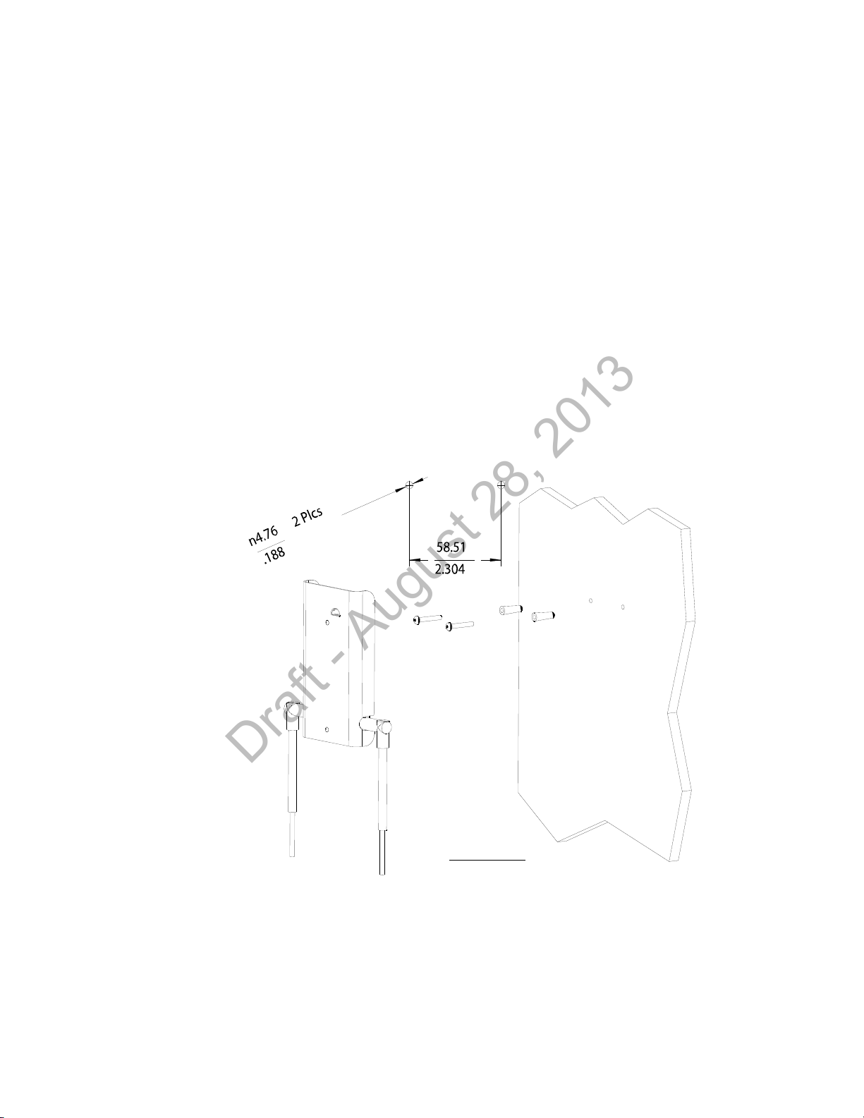
Mounting the IntelliVue Smart-hopping Remote Antenna to a Wall (Fixed Mount)
Units: millimeters
inches
Draft - August 28, 2013
Mounting the IntelliVue Smart-hopping Remote Antenna to a Wall (Fixed
Mount)
You can mount the IntelliVue Smart-hopping Remote Antenna (RA) to a wall using
the mounting screws and screw anchors supplied with the RA. We recommend that
you mount the RA high on the wall as close to the ceiling as possible.
To mount the 1.4 GHz IntelliVue Smart-hopping RA to a wall:
1. Using a 3/16-inch drill bit, drill two pilot holes 0.188 inches (5 mm) in diameter
at the locations shown in Figure 2-14.
2. Tap a supplied plastic screw anchor into each pilot hole until it is flush with the
wall surface.
This step is not necessary if mounting the IntelliVue Smart-hopping RA on a
wood surface.
3. Screw a supplied #6 x 1 1/4 inch self-tapping screw into each screw anchor (or
pilot hole) as shown in Figure 2-14.
Tighten each screw until a 1/16-inch (2 mm) gap remains between the screw
head and the mounting surface.
Figure 2-14: Mounting the IntelliVue Smart-hopping 1.4 GHz Remote Antenna to a
4. While holding the RA chassis with its antennas pointing down as shown in
Figure 2-14, fit the holes in the back of the RA chassis over the screw heads
IntelliVue Smart-hopping 1.4 GHz High-power Access Point Installation Guide 2-21
Wall
Page 44

Chapter 2: Installing the IntelliVue Smart-hopping 1.4 GHz Core Access Point
Draft - August 28, 2013
that protrude from the wall. Slide the RA chassis down so that the screw heads
are securely in the grooves in the back of the RA chassis.
2-22
Page 45
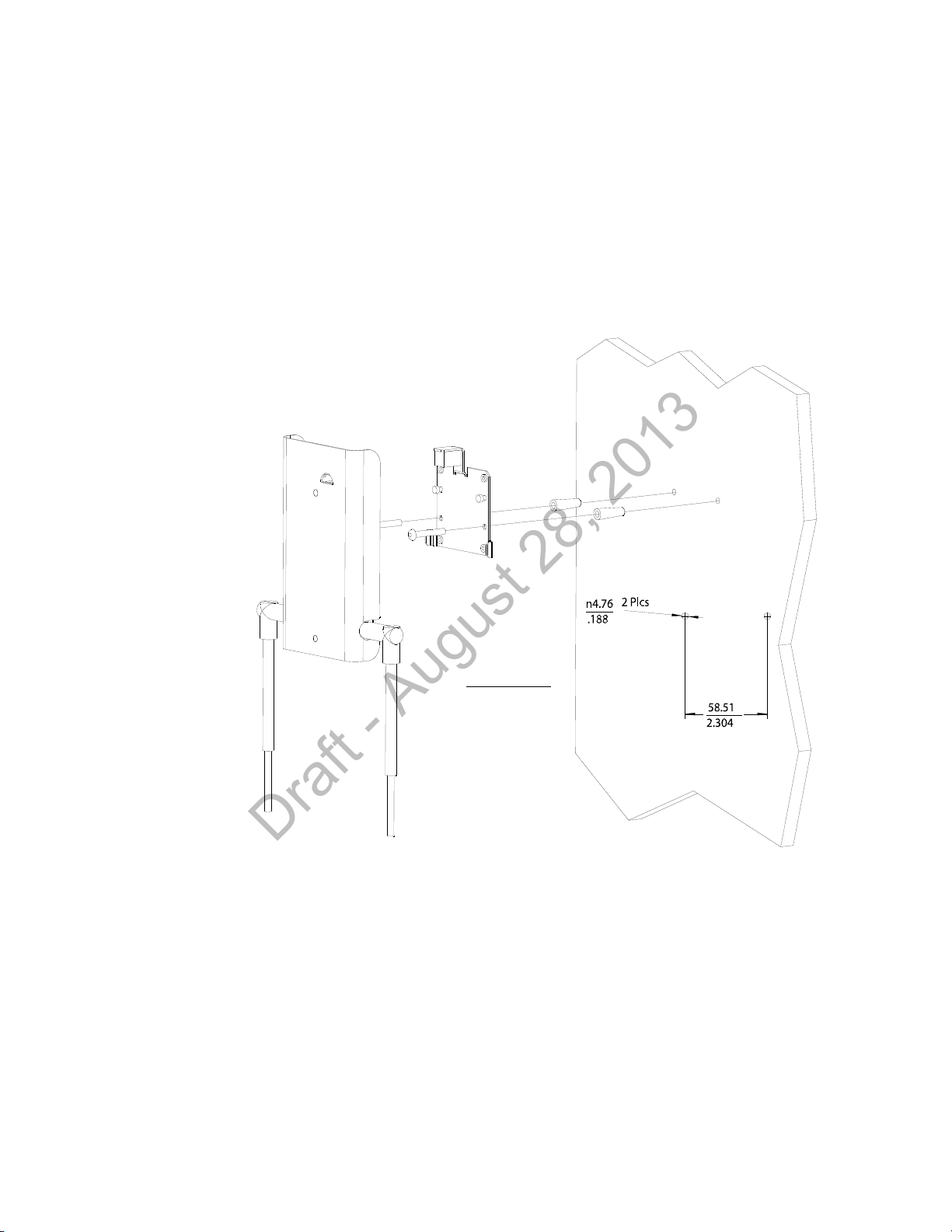
Mounting the IntelliVue Smart-hopping Remote Antenna to a Wall (CA Earthquake Rated)
Units: millimeters
inches
Draft - August 28, 2013
Mounting the IntelliVue Smart-hopping Remote Antenna to a Wall (CA
Earthquake Rated)
You can mount the IntelliVue Smart-hopping Remote Antenna onto walls using an
optional California (CA) earthquake-rated wall plate. Use of this quick release wall
plate enables you to relocate 1.4 GHz IntelliVue Smart-hopping RAs within your
facility quickly and easily.
To mount the 1.4 GHz IntelliVue Smart-hopping RA to a wall:
1. Using a 3/16-inch drill bit, drill two pilot holes 0.188 inches (5 mm) in diameter
at the locations shown in Figure 2-15.
Figure 2-15: Mounting the IntelliVue Smart-hopping 1.4 GHz RA to a Wall (CA Earth-
2. Tap a supplied plastic screw anchor into each pilot hole until flush with the wall
surface.
This step is not necessary if mounting the IntelliVue Smart-hopping RA on a
wood surface.
3. Secure the quick release wall plate to the wall by screwing a supplied #6 x 1
1/4 inch self-tapping screw through the wall plate into each screw anchor (or
IntelliVue Smart-hopping 1.4 GHz High-power Access Point Installation Guide 2-23
pilot hole) as shown in Figure 2-15.
Tighten each screw until the wall plate is fixed securely in place.
quake Rated)
Page 46

Chapter 2: Installing the IntelliVue Smart-hopping 1.4 GHz Core Access Point
Draft - August 28, 2013
4. While holding the RA chassis with its antennas pointing down as shown in
Figure 2-15, fit the openings in the back of the RA chassis over the two
mounting studs that protrude from the wall plate, and then slide the RA chassis
down so that the mounting studs are securely in the grooves in the back of the
RA chassis.
2-24
Page 47

Mounting the IntelliVue Smart-hopping Remote Antenna Above a Ceiling Tile (Mounting Rails)
Draft - August 28, 2013
Mounting the IntelliVue Smart-hopping Remote Antenna Above a Ceiling Tile
(Mounting Rails)
You can mount the IntelliVue Smart-hopping Remote Antenna (RA) above a ceiling
tile by using the mounting rails provided in the Above & Below Ceiling Tile Mount Kit
(862415-K05) for the Core AP and Remote Antennas.
Caution When installing the IntelliVue Smart-hopping Remote Antenna onto a suspended
ceiling, make certain the ceiling grid is structurally rated to support the weight of the
Remote Antenna, 0.32 kg (.7 lbs), and any extra cabling.
To mount the 1.4 GHz IntelliVue Smart-hopping RA above a ceiling tile:
1. Determine which ceiling tile the RA will be mounted onto, and the approximate
RA placement and orientation of the antennas on the tile. Also, check for
adequate clearance above the RA.
2. Remove the ceiling tile to which the RA will be mounted (and also an adjacent
tile to facilitate installation).
3. Orient the antenna(s) on the RA chassis so they bend downward at right angles
to the chassis. Unscrew the collar and rotate the antenna into position and then
retighten the collar to secure the antenna in place.
4. Determine where the two holes for the antennas are going to be located on the
tile and mark the centers of the holes.
The RA chassis can be rotated 90 degrees to the mounting rails. Choose the
best placement of the RA to facilitate where the antennas will go through the
ceiling tile. Note that there are two holes in the RA chassis to allow for tethering
to other permanent structures where local building codes require this type of
installation. Refer to Figure 2-16 or Figure 2-17 for the dimensions to locate the
antenna holes in the ceiling tile.
5. Drill out two 3/4-inch (19 mm) diameter holes in the ceiling tile for the
antennas. Lightly coat both plastic grommets with silicone adhesive and insert
them into both holes in the tile (insert grommets from the outside of the tile).
6. Secure the mounting rails to the RA. Insert the four (4) M3 X 0.5 (8 mm LG)
screws into the RA mounting rail holes, and into the mating holes in the back of
the RA chassis as shown in Figure 2-17 or Figure 2-18. Torque-tighten each
screw to 8-inch lbs.
7. Place the RA with mounting rails across the top of the tile.
8. Replace the tile back onto the ceiling frame structure with the RA antennas
hanging down through the ceiling. Wiring connections to the RA can be
accessed via the open adjacent tile.
9. Replace other adjacent ceiling tiles if necessary.
IntelliVue Smart-hopping 1.4 GHz High-power Access Point Installation Guide 2-25
Page 48
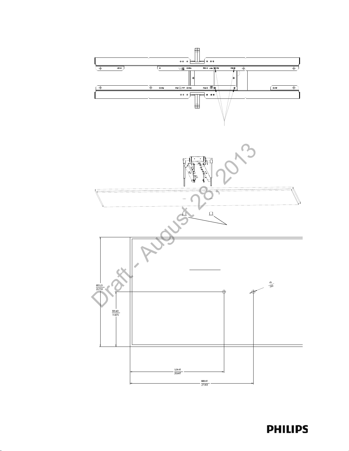
Chapter 2: Installing the IntelliVue Smart-hopping 1.4 GHz Core Access Point
Use These Holes Marked as Noted
RM2 RM2
AM2 Unmarked
Grommets
Units: millimeters
inches
Draft - August 28, 2013
Figure 2-16: Possible Above the Ceiling Remote Antenna Mounting Position
2-26
Page 49
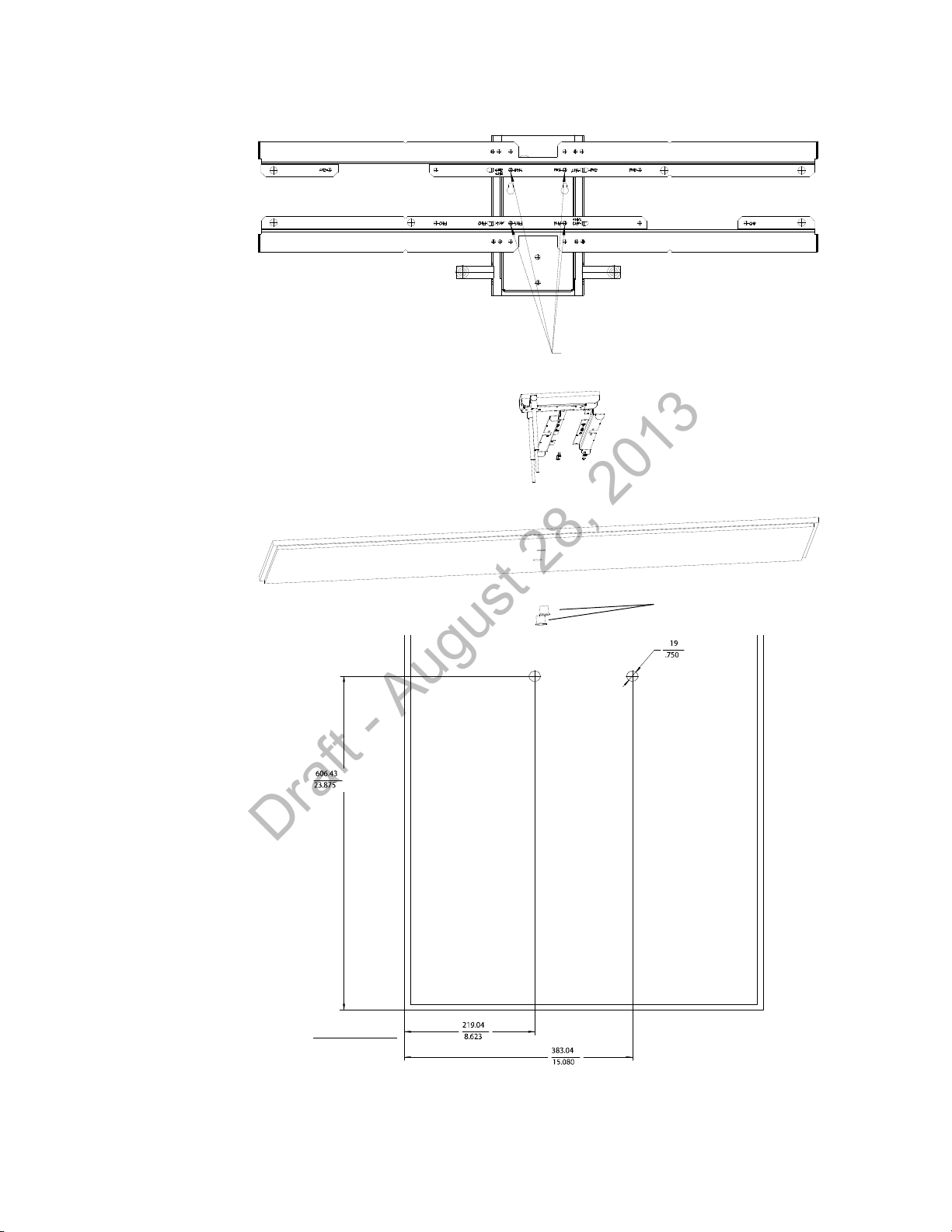
Mounting the IntelliVue Smart-hopping Remote Antenna Above a Ceiling Tile (Mounting Rails)
Use These Holes Marked RM4
Grommets
Units: millimeters
inches
Draft - August 28, 2013
Figure 2-17: Alternative Above the Ceiling Remote Antenna Mounting Position
IntelliVue Smart-hopping 1.4 GHz High-power Access Point Installation Guide 2-27
Page 50

Chapter 2: Installing the IntelliVue Smart-hopping 1.4 GHz Core Access Point
Draft - August 28, 2013
Mounting the IntelliVue Smart-hopping Remote Antenna Above a Ceiling Tile (Tether Mount)
You can mount the IntelliVue Smart-hopping Remote Antenna (RA) above a ceiling
tile without the use of mounting rails if the following conditions are met:
• The ceiling tile can support the weight of the RA, 0.32 kg (.7 lbs), and any extra
cabling.
• The RA is tethered securely to a permanent structure within the ceiling.
• A minimum of 12-gauge galvanized soft annealed mild steel wire conforming to
ASTM A 641 is used to tether the RA chassis to a permanent structure within the
ceiling.
To mount the 1.4 GHz IntelliVue Smart-hopping RA above a ceiling tile:
1. Determine which ceiling tile the RA is be mounted onto, and the approximate RA
placement and orientation of the antennas on the tile. Also, check for adequate
clearance above the RA.
2. Remove the ceiling tile to which the RA will be mounted (and also an adjacent
tile to facilitate installation).
3. Orient the antenna(s) on the RA chassis so they bend downward at right angles
to the chassis. Unscrew the collar and rotate the antenna into position and then
retighten the collar to secure the antenna in place.
4. Determine where the two holes for the antennas are going to be located on the
tile and mark the centers of the holes.
Note that the RA antennas can be placed, and oriented in a variety of places to
accommodate positioning the antennas through the tile (e.g., close to a side
wall).
Also, the RA chassis can be rotated 90 degrees. Choose the best placement of
the RA to facilitate where the antennas will go through the ceiling tile. Refer to
Figure 2-16 or Figure 2-17 for the dimensions to locate the antenna holes in the
ceiling tile.
5. Drill out two 3/4-inch (19 mm) diameter holes in the ceiling tile for the
antennas. Lightly coat both plastic grommets with silicone adhesive and insert
them into both holes in the tile (insert grommets from the outside of the tile).
6. Insert the tether wire through the two holes located at the corner of the RA
chassis. The tether wire should have three tight turns of the wire within 1.5
inches of the end of the wire.
7. Connect the other end of the tether wire to a permanent structure within the
ceiling. The tether wire may be attached to any of the following:
• wood or metal stud framing
• blocking attached to wood or metal framing
• plywood adequately attached to wood or metal stud framing, reinforced
concrete, or reinforced masonry
• reinforced concrete
• reinforced masonry
2-28
Page 51

Mounting the IntelliVue Smart-hopping Remote Antenna Above a Ceiling Tile (Tether Mount)
Draft - August 28, 2013
8. Place the RA across the top of the tile.
9. Replace the tile back onto the ceiling frame structure with the RA antennas
hanging down through the ceiling. Wiring connections to the RA can be
accessed via the open adjacent tile.
10. Replace other adjacent ceiling tiles if necessary.
IntelliVue Smart-hopping 1.4 GHz High-power Access Point Installation Guide 2-29
Page 52

Chapter 2: Installing the IntelliVue Smart-hopping 1.4 GHz Core Access Point
Draft - August 28, 2013
Mounting the IntelliVue Smart-hopping Remote Antenna Below a Ceiling Tile (Fixed Mount)
You can mount the IntelliVue Smart-hopping Remote Antenna (RA) below a ceiling
tile by using the mounting rails provided in the Above & Below Ceiling Tile Mount Kit
(862415-K05) for the Core AP and Remote Antennas.
Caution When installing the IntelliVue Smart-hopping Remote Antenna onto a suspended
ceiling, make certain the ceiling grid is structurally rated to support the weight of the
Remote Antenna, 0.32 kg (.7 lbs), and any extra cabling.
To mount the 1.4 GHz IntelliVue Smart-hopping RA below a ceiling tile:
1. Determine which ceiling tile the RA is be mounted onto, and the approximate
placement of the RA and orientation of the antennas hanging down from the
ceiling tile.
2. Remove the ceiling tile the RA will be mounted to (and also the adjacent tile to
facilitate installation).
3. Refer to Figure 2-18 for all dimensions and hole locations. Place the mounting
rails across the tile (underside of tile). For ceiling tiles that are smaller than
standard 2’ x 4’ size ceiling tile, the mounting rails can be cut down in length at
the u-shaped cutouts.
4. Mark the location of the RB screw holes in the mounting rails on the ceiling tile
where the holes will be drilled through the tile as shown in Figure 2-19. Drill four
0.25-inch (6 mm) diameter holes in the ceiling tile.
5. Determine where the hole for the Core AP cable is going to be located on the tile
and mark the center of the hole.
6. Drill or cut out a 0.813-inch (21 mm) diameter hole for the Core AP cable to be
connected to the RA. Lightly coat a plastic grommet with silicone adhesive and
insert it into the hole in the tile (insert grommet from the outside of the tile).
7. Insert the four (4) M3-.5 x 30 lobe screws into the RA mounting rail holes,
through the ceiling tile, through the provided plastic spacers, and into the
mating holes in the back of the RA chassis as shown in Figure 2-20. Torquetighten each screw to 8-inch lbs.
Note that the RA mounting rails and spacers allow for sufficient airflow between
the RA and the ceiling tile.
8. Orient the antenna(s) on the RA chassis so they bend upward at right angles to
the chassis. Unscrew the collar and rotate into position and then retighten the
collar to secure the antenna in place.
9. Replace the tile back onto the ceiling frame structure with the RA antennas
hanging down from the ceiling. Cabling connections to the RA can be accessed
via the open holes in the tile.
Note that there are additional holes in the mounting rails to allow for tethering
to other permanent structures where local building codes require this type of
installation.
10. Replace other adjacent ceiling tiles if necessary.
2-30
Page 53
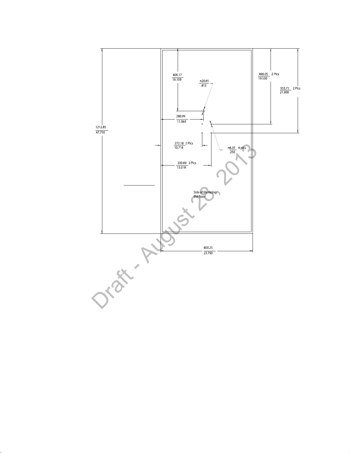
Mounting the IntelliVue Smart-hopping Remote Antenna Below a Ceiling Tile (Fixed Mount)
Units: millimeters
inches
Draft - August 28, 2013
IntelliVue Smart-hopping 1.4 GHz High-power Access Point Installation Guide 2-31
Figure 2-18: RA Below Ceiling Tile Hole Locations and Dimensions
Page 54
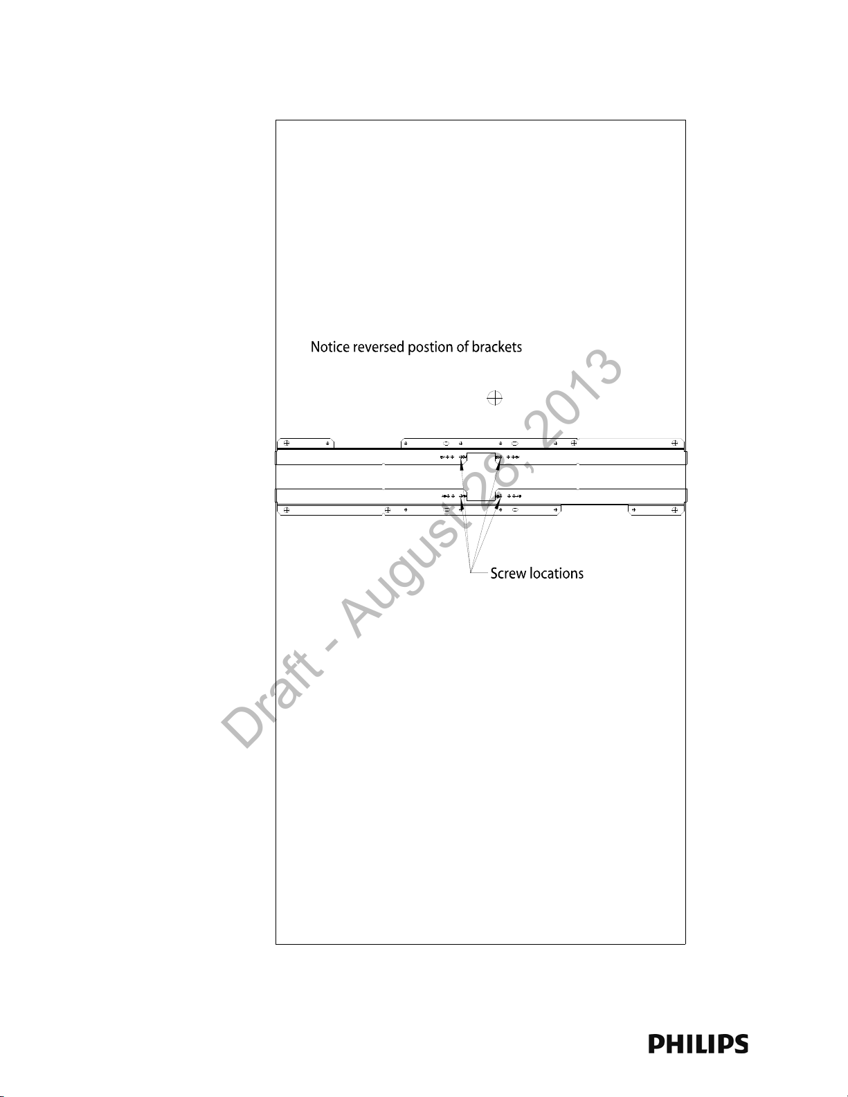
Chapter 2: Installing the IntelliVue Smart-hopping 1.4 GHz Core Access Point
Use the Screw Locations
Marked RB
Draft - August 28, 2013
Figure 2-19: RA Below Ceiling Tile Mounting Rail Screw Locations
2-32
Page 55
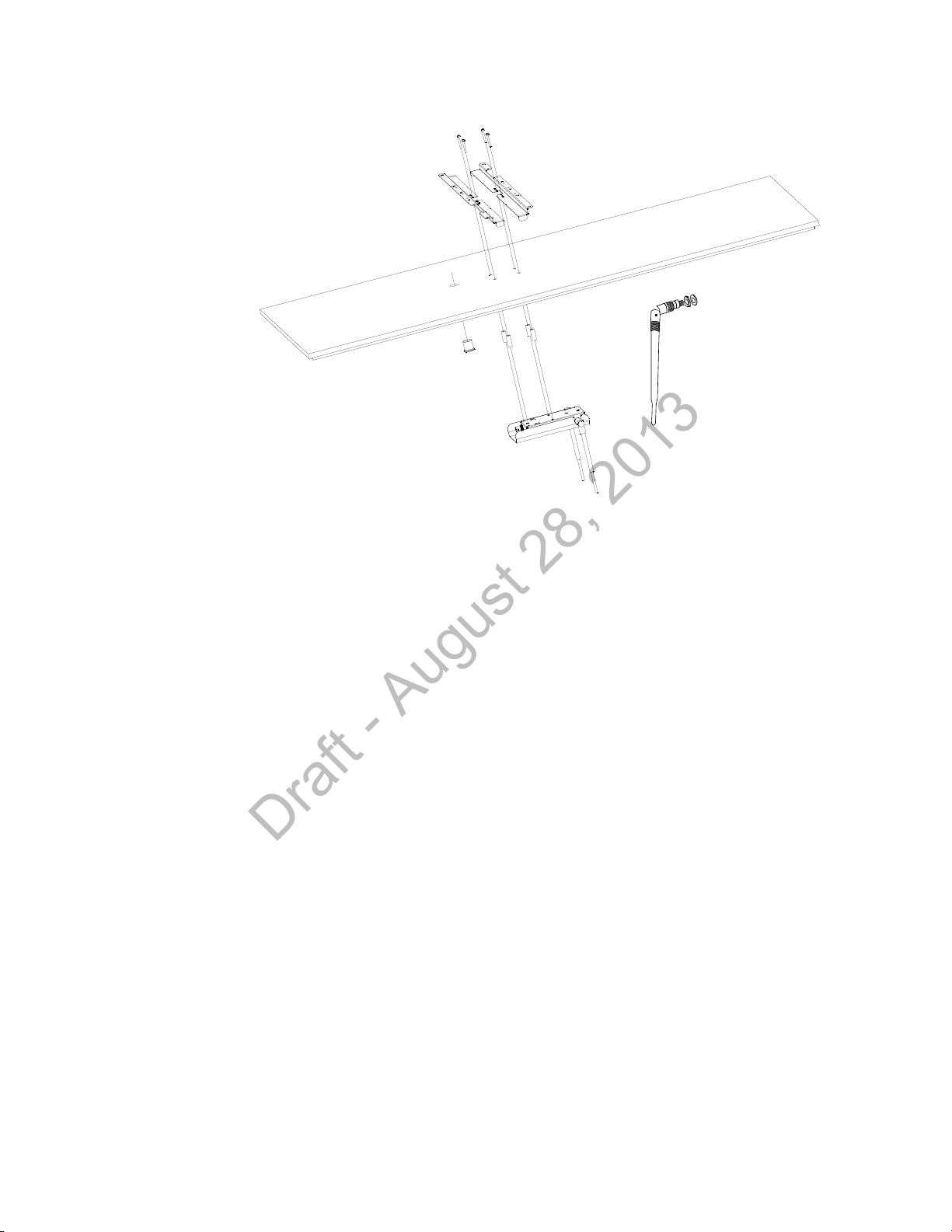
Mounting the IntelliVue Smart-hopping Remote Antenna Below a Ceiling Tile (Fixed Mount)
Bend Down
Tighten Collar
Draft - August 28, 2013
Figure 2-20: Mounting the RA Below a Ceiling Tile (Fixed Mount)
IntelliVue Smart-hopping 1.4 GHz High-power Access Point Installation Guide 2-33
Page 56
Chapter 2: Installing the IntelliVue Smart-hopping 1.4 GHz Core Access Point
Draft - August 28, 2013
Mounting the IntelliVue Smart-hopping RA Below a Ceiling Tile (Quick Release)
You can mount the IntelliVue Smart-hopping Remote Antenna below a ceiling tile by
using an optional quick release wall plate along with the mounting rails provided in
the Above & Below Ceiling Tile Mount Kit (862415-K05) for the Core AP and Remote
Antennas. Use of this wall plate enables you to relocate 1.4 GHz IntelliVue Smarthopping RAs within your facility quickly and easily.
Caution When installing the IntelliVue Access Point onto a suspended ceiling, make certain
the ceiling grid is structurally rated to support the weight of the Access Point, 0.7kg
(1.5 lbs), and any extra cabling.
To mount the 1.4 GHz IntelliVue Smart-hopping RA below a ceiling tile:
1. Determine which ceiling tile the RA will be mounted onto, and the approximate
placement of the RA and orientation of the antennas hanging down from the
ceiling tile.
2. Remove the ceiling tile to which the RA will be mounted (and also the adjacent
tile to facilitate installation).
3. Refer to Figure 2-21 for all dimensions and hole locations. Place the mounting
rails across the tile (underside of tile). For ceiling tiles that are smaller than
standard 2’ x 4’ size ceiling tile, the mounting rails can be cut down in length at
the u-shaped cutouts.
4. Mark the location of the “RB” screw holes in the mounting rails on the ceiling
tile where the holes will be drilled through the tile as shown in Figure 2-22. Drill
four 0.25-inch (6 mm) diameter holes in the ceiling tile.
5. Determine where the two holes for the Remote Antenna cabling are going to be
located on the tile and mark the centers of the hole.
6. Drill or cut out a 0.813-inch (21 mm) diameter hole for the Core AP cable to be
connected to the RA. Lightly coat a plastic grommet with silicone adhesive and
insert it into each hole in the tile (insert grommet from the outside of the tile).
7. Place the wall plate over the four holes drilled on the bottom of the tile. Note:
The top direction is as when the tile is in its installed position.
8. Insert the four (4) M3-.5 x 30 lobe screws into the RA mounting rail holes,
through the ceiling tile, through the provided plastic spacers, and into the
mating holes in the back of the wall plate.
9. Fit the openings in the back of the RA chassis over the two mounting studs that
protrude from the wall plate and then slide the RA chassis so that the mounting
studs are securely in the grooves in the back of the RA chassis.
2-34
Page 57
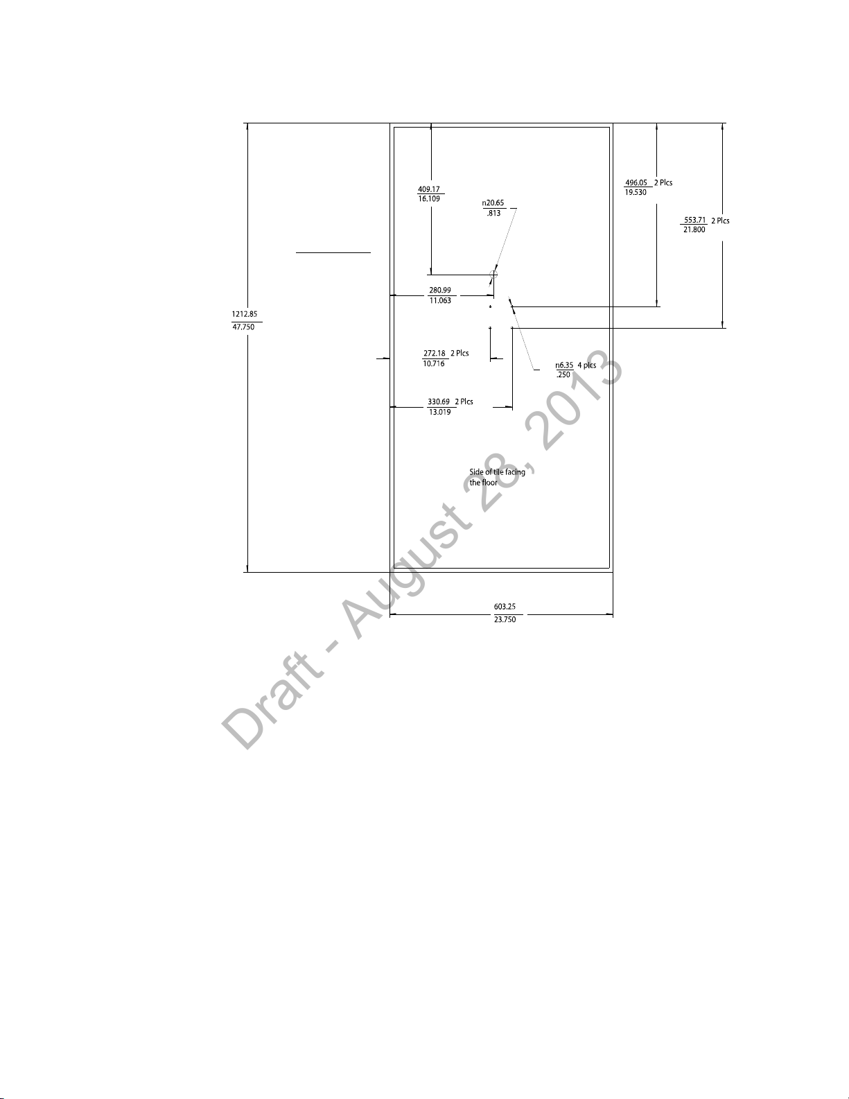
Mounting the IntelliVue Smart-hopping RA Below a Ceiling Tile (Quick Release)
Units: millimeters
inches
Draft - August 28, 2013
IntelliVue Smart-hopping 1.4 GHz High-power Access Point Installation Guide 2-35
Figure 2-21: RA Below Ceiling Tile Hole Locations and Dimensions
Page 58
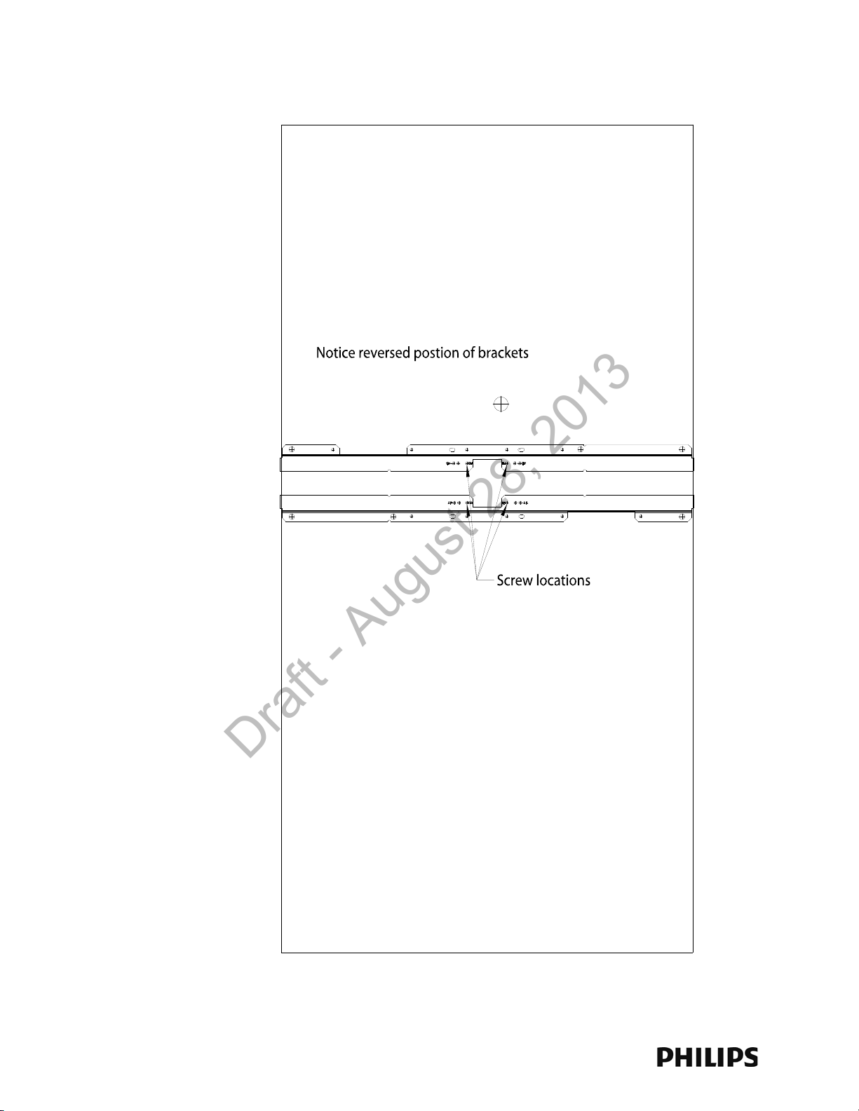
Chapter 2: Installing the IntelliVue Smart-hopping 1.4 GHz Core Access Point
Use the Screw Locations
Marked RB
Draft - August 28, 2013
Figure 2-22: RA Below Ceiling Tile Mounting Rail Screw Locations
2-36
Page 59
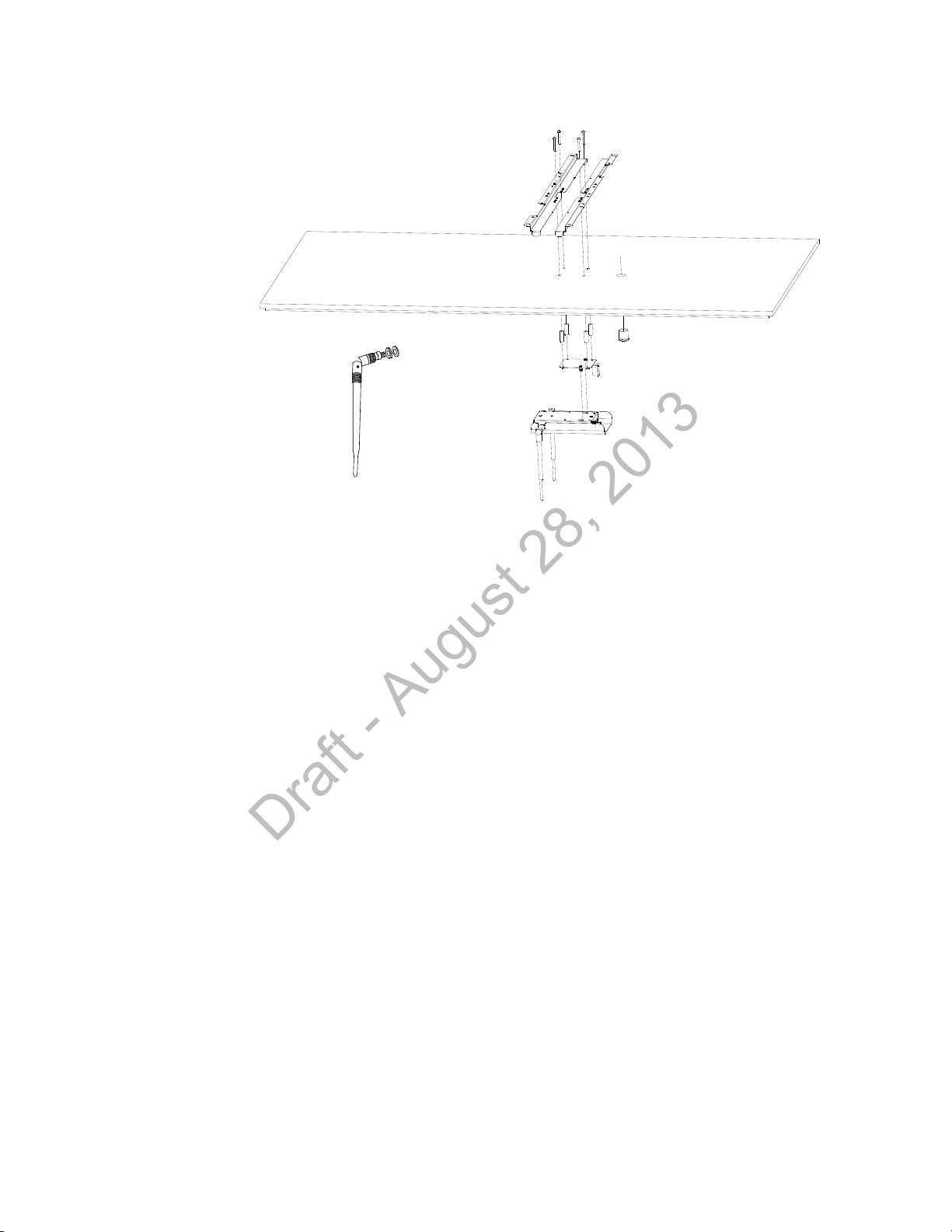
AP Configuration Information
Bend Down
Tighten Collar
Draft - August 28, 2013
Figure 2-23: Mounting the RA Below a Ceiling Tile (Quick Release
AP Configuration Information
Refer to the IntelliVue Smart-hopping Infrastructure Installation and Service Guide
for complete details about configuring the IntelliVue Smart-hopping AP.
Access Point Startup Sequence
Upon power on/start up, the IntelliVue Smart-hopping Core Access Point will
perform a Power-on-Self-Test (POST) to ensure that its basic components are fully
functional.
This test detects critical system failures. As the test progresses the state of the
system is displayed through a series of color combinations on the Power/Sync,
Radio, and Network LEDs on the front of the AP. All three LEDs illuminate AMBER
color, then the Power/Sync LED illuminates GREEN and the other two LEDs turn off
(not illuminated) indicating correct startup. Should a test fail the LEDs are left in a
state which indicates the point at which the test failed. When the system is
transmitting data the radio and network LEDs on the AP will flicker on and off as
data is transmitted.
IntelliVue Smart-hopping 1.4 GHz High-power Access Point Installation Guide 2-37
Page 60

Chapter 2: Installing the IntelliVue Smart-hopping 1.4 GHz Core Access Point
Draft - August 28, 2013
2-38
Page 61

3
Maintaining the IntelliVue Smart-hopping 1.4 GHz
Draft - August 28, 2013
Core Access Point
This chapter provides procedures and information for maintaining the
Philips IntelliVue Smart-hopping 1.4 GHz Core Access Point and includes:
• Maintenance Procedure
• Troubleshooting the Core AP Using its LEDs
• Replacing a Core AP or Remote Antenna
• Ordering Replacement Parts
IntelliVue Smart-hopping 1.4 GHz High-power Access Point Installation Guide 3-1
Page 62
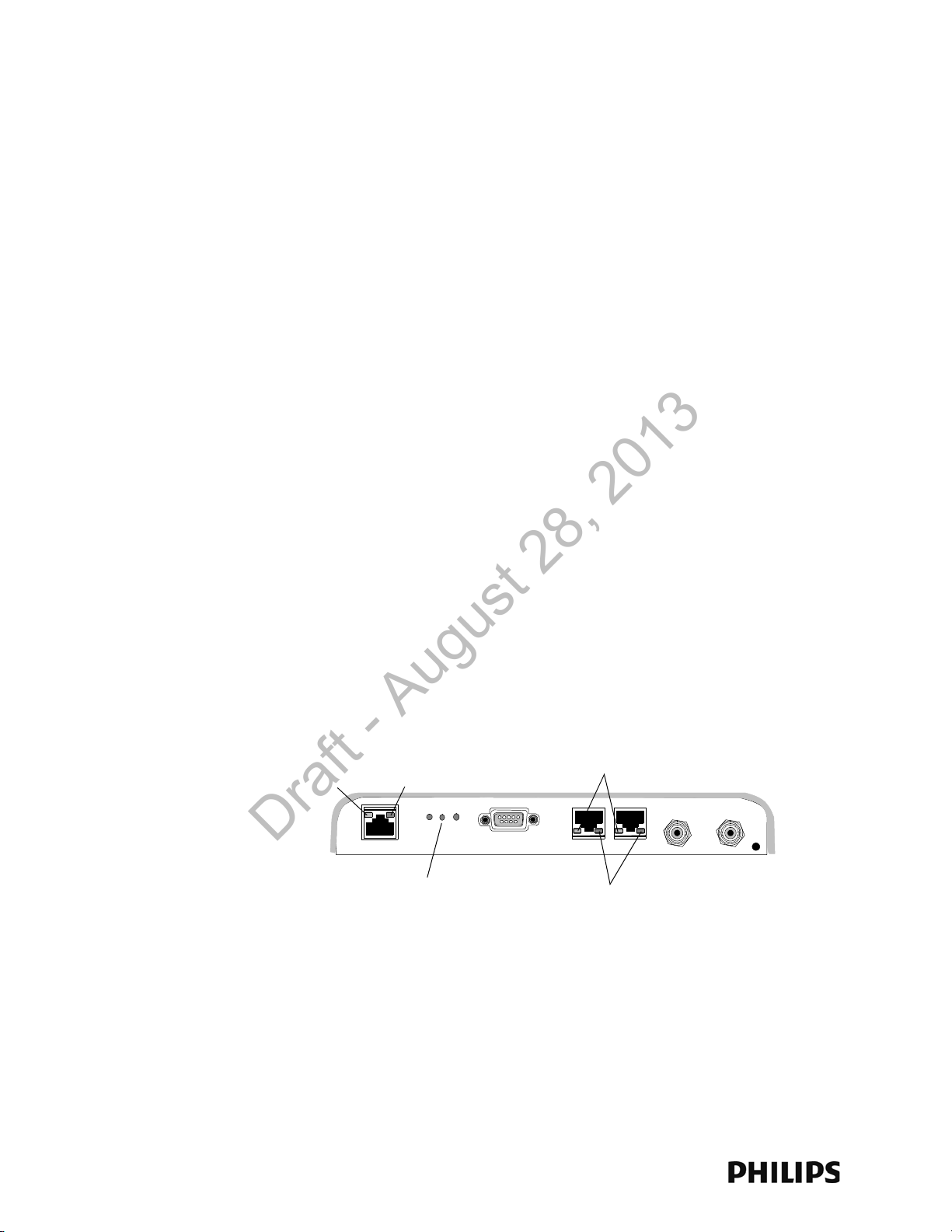
Chapter 3: Maintaining the IntelliVue Smart-hopping 1.4 GHz Core Access Point
Power/Sync, Radio, Network
Status LEDs
Link LED
Activity LED
RA Connection LEDs
RA Power LEDs
Draft - August 28, 2013
Maintenance Procedure
To ensure that IntelliVue Smart-hopping 1.4 GHz Core Access Point (AP) and Remote
Antenna (RA) continue to operate properly, you should perform the following
maintenance tasks periodically:
• Ventilation - The IntelliVue Smart-hopping 1.4 GHz Core Access Point and RA
cases are vented to provide air circulation and cooling for the devices. Keep the
immediate area around the AP and RA open to allow for natural air circulation
around the devices. Periodically, dust the AP and RA cases to keep their
ventilation holes open.
• Antenna Orientation - Under normal operation the AP or RA antennas may get
bumped by cleaning crews and/or construction crews and causing the
antennas to move from their original position set at installation.
Periodically check the antennas on all of the APs and RAs at the installation site
for correct orientation, alignment, direction, and placement. If necessary,
loosen the collar on the antenna and adjust the antenna for proper placement,
orientation, and direction. Then, re-tighten the antenna collar to secure the
antenna in place. Generally, you should orient the two local antennas on each
Core AP and RA such that they are perpendicular to the floor.
Troubleshooting the Core AP Using its LEDs
Complete test and inspection procedures for the IntelliVue Smart-hopping 1.4 GHz
Core Access Point are given in Chapter 5 of the IntelliVue Smart-hopping
Infrastructure Installation and Service Guide. You must perform these procedures
when the IntelliVue Smart-hopping Access Point is initially installed and after any
service event.
Figure 3-1 shows the location of the IntelliVue Smart-hopping 1.4 GHz Core Access
Point LEDs.
Figure 3-1: IntelliVue Smart-hopping Core Access Point LEDs
A summary of the Core AP’s system status LEDs is given below to help you
troubleshoot any AP operational problems that may arise.
The IntelliVue Smart-hopping Core AP provides the following status LEDs.
3-2
Page 63
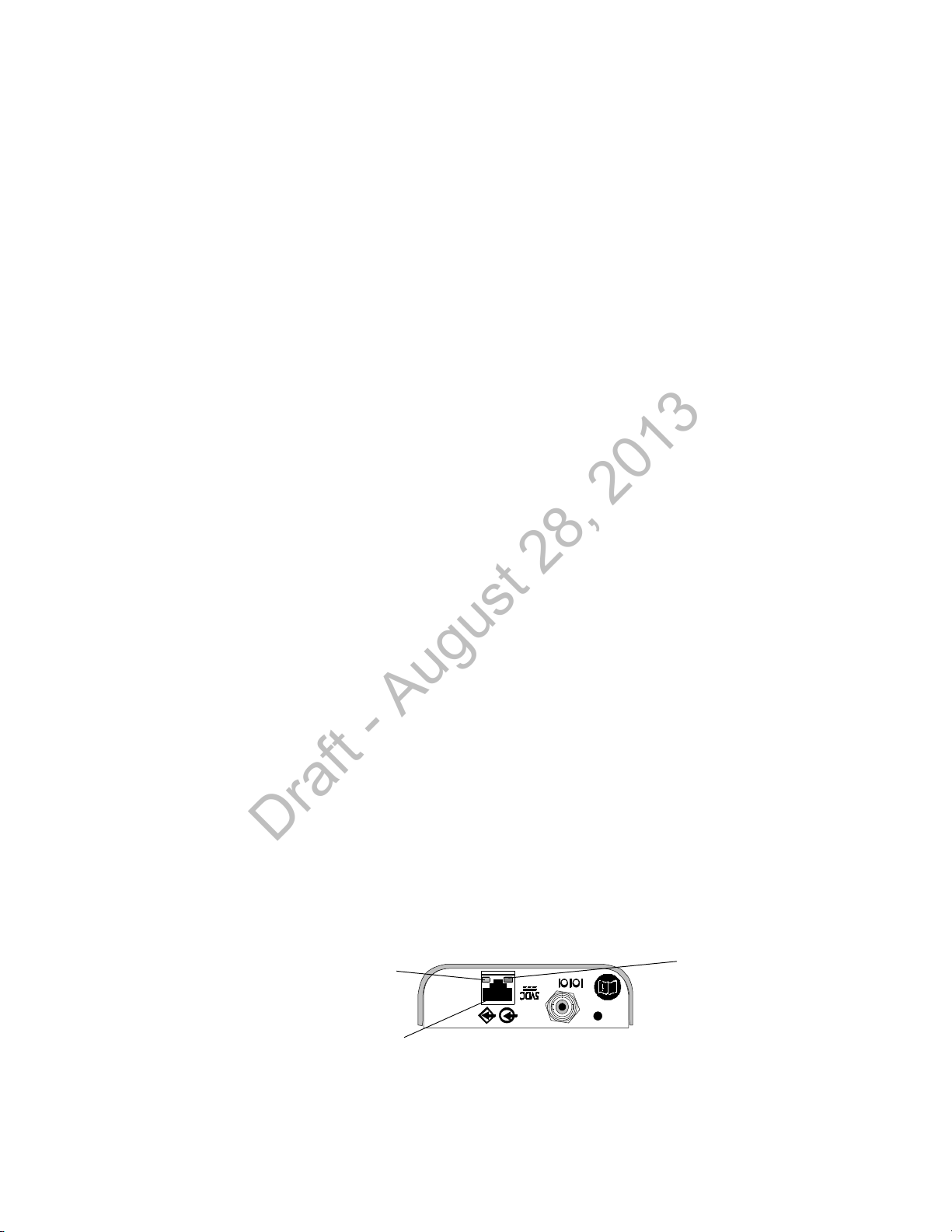
Troubleshooting the Remote Antenna Using its LEDs
UTP Cable Connector
to Core AP
Connection LED
(Green)
Power LED
(Yellow)
Draft - August 28, 2013
• Wired/Ethernet Activity - The Core AP provides two LEDs to indicate wired/
Ethernet activity to the IntelliVue Smart-hopping infrastructure. During normal
operation, these LEDs indicate the following information:
- Link LED - Link present/Ethernet connection. Lights GREEN (ON) when a
pass-through link is present - OFF when not present.
- Act LED - Wired network activity. Flashes GREEN (ON) when there is activity is
over the wired network.
• Wireless/RF Activity - The AP provides three LEDs to indicate wireless/RF
activity. During normal operation, these LEDs indicate the following information:
- Power/Sync LED - GREEN (ON) when power and synchronization signal is
present.
- Radio LED - Normally OFF (not lit) - flashes green to indicate wireless network
activity.
- Network LED - Normally OFF (not lit) - flashes green to indicate wired network
activity.
• Remote Antenna - The Core AP provides two LEDs on each RJ-45 UTP cable
connector that provides status on a connected Remote Antenna:
- RA Connection - Lights GREEN to indicate a RA is connected to the Core AP.
- RA Power - Lights YELLOW to indicate connected RA is receiving power from
the Core AP.
If the Status LED indicators are not functioning properly as indicated then perform
the appropriate troubleshooting procedures. If you cannot resolve the problem with
the LEDs, then make written note of the LED lighting and sequence of colors,
replace the unit, and send the defective unit back to Philips with the explanation of
LEDs sequence and colors displayed. Refer to Chapter 4 of the IntelliVue Smart-
hopping Infrastructure Installation and Service Guide for complete AP replacement
procedures.
Troubleshooting the Remote Antenna Using its LEDs
Complete test and inspection procedures for the IntelliVue Smart-hopping 1.4 GHz
Remote Antenna are given in Chapter 5 of the IntelliVue Smart-hopping
Infrastructure Installation and Service Guide. You must perform these procedures
when the Remote Antenna is initially installed and after any service event.
Figure 3-1 shows the location of the IntelliVue Smart-hopping 1.4 GHz Remote
Antenna LEDs.
IntelliVue Smart-hopping 1.4 GHz High-power Access Point Installation Guide 3-3
Page 64

Chapter 3: Maintaining the IntelliVue Smart-hopping 1.4 GHz Core Access Point
Draft - August 28, 2013
Figure 3-2: IntelliVue Smart-hopping Remote Antenna LEDs
A summary of the Remote Antenna’s status LEDs is given below to help you
troubleshoot any operational problems that may arise.
• Remote Antenna - The Core AP provides two LEDs on each RJ-45 UTP cable
connector that provides status on a connected Remote Antenna:
- RA Connection - Lights GREEN to indicate a RA is connected to the Core AP.
- RA Power - Lights YELLOW to indicate connected RA is receiving power from
the Core AP.
If the Status LED indicators are not functioning properly as indicated, then refer to
the sections that follow and Chapter 4 of the IntelliVue Smart-hopping
Infrastructure Installation and Service Guide for complete Remote Antenna
replacement procedures.
Replacing a Core AP or Remote Antenna
The repair strategy for the IntelliVue Smart-hopping Core Access Point or Remote
Antenna is unit replacement. No repairs are to be made to the Core AP or RA.
Individual AP or RA components, PC assemblies, or sub-assemblies are not
available for purchase.
If a IntelliVue Smart-hopping Core AP or RA is determined to be defective/nonoperational, call your local Philips Field Service Engineer/Customer Engineer or the
Philips Customer Care Solutions Center for information on ordering a replacement
unit and returning the defective unit.
Use the following toll-free number to contact the Philips Customer Care Solutions
Center:
• Telephone: (+1) 800-722-9377
When replacing defective equipment on your IntelliVue Smart-hopping
infrastructure, be sure to follow the procedures given in Chapter 5 of the IntelliVue
Smart-hopping Infrastructure Installation and Service Guide.
Ordering Replacement Parts
This section contains information for ordering replaceable parts and assemblies for
the IntelliVue Smart-hopping 1.4 GHz Core Access Point and Remote Antenna. The
parts are listed in tables by major assemblies. Each table contains the orderable
part number (New or Exchange) and a description of the part. Only the part
numbers listed are orderable. Any unlisted part numbers and part descriptions are
not orderable from Philips.
To order a replacement part, first identify the faulty component, part, subassembly
or assembly, then look in the associated table for that major assembly and find (and
record) the part description and replaceable part number. Order replaceable parts
from your nearest Philips Sales/Service office or from the Philips Support Materials
Organization. A complete listing of the Philips Sales/Service Offices addresses with
phone numbers can be found at the end of this chapter.
3-4
Page 65
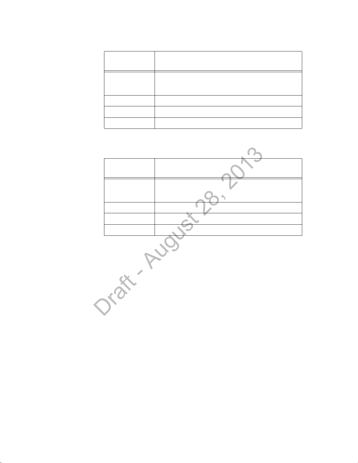
Ordering Replacement Parts
Draft - August 28, 2013
Table 3-1: Ordering Core Access Point Replacement Parts
New
Part Number
453564235171 IntelliVue Core Access Point, 1.4 GHz. Complete AP unit
includes the following: AP Case (top cover and shell), Main PC
Board, Radio Module PC Board, and Two External Antennas.
453564079561 1.4 GHz Antenna with SMA-style Connector
453564052201 Core AP/Remote Antenna Ceiling Mount Kit
453564090571 Ferrite Core Block
Table 3-2: Ordering Remote Antenna Replacement Parts
New
Part Number
453564036561 IntelliVue Remote Antenna, 1.4 GHz. Complete unit includes the
following: RA Case (top cover and shell), Main PC Board, Radio
Module PC Board, and Two External Antennas.
453564079561 1.4 GHz Antenna with SMA-style Connector
453564056081 Plenum, 74 ft. (22.6m), Coax & Data Cable Assembly
Description
Description
453564052201 Core AP/Remote Antenna Ceiling Mount Kit
IntelliVue Smart-hopping 1.4 GHz High-power Access Point Installation Guide 3-5
Page 66

Chapter 3: Maintaining the IntelliVue Smart-hopping 1.4 GHz Core Access Point
Draft - August 28, 2013
Philips Sales and Support Offices Worldwide
Please call your local sales office listed in your telephone directory or a regional
office listed below for the location of your nearest sales office.
CORPORATE HEADQUARTERS:
Philips Medical Systems
Netherlands B.V.
Postbus 10.000
5680 DA Best
Netherlands
UNITED STATES:
Philips Medical Systems
3000 Minuteman Road
Andover, MA 01810
(800) 934-7372
CANADA:
Philips Medical Systems
281 Hillmount Road
Markham, ON L6C 2S3
(800) 291-6743
EUROPE, MIDDLE EAST AND AFRICA:
Philips Medizin Systeme Böblingen GmbH
Cardiac and Monitoring Systems
Hewlett-Packard Str. 2
71034 Böblingen
Germany
Fax: (+49) 7031 463 1552
LATIN AMERICA HEADQUARTERS:
Philips Medical Systems
1550 Sawgrass Corporate Parkway #300
Sunrise, FL 33323
Tel: 954-835-2600
Fax: 954-835-2626
ASIA PACIFIC HEADQUARTERS:
Philips Medical Systems
30/F Hopewell Centre
17 Kenn e d y Road
Wanchai
Hong Kong
Tel: (852) 2821 5888
Fax: (852) 2527 6727
3-6
Page 67

A
Draft - August 28, 2013
Access points
cluster AP descriptions 1-3
Ethernet interface on cluster APs 1-6
illustration of 3-2, 3-4
illustration of cluster AP 1-3
mounting options for cluster AP 1-4
overview of Cluster APs 1-3
placement guidelines 2-2
serial port 1-7
status LEDs 1-8, 3-2
Act LED 1-8, 3-3
C
Coaxial Cable Connectors on Core AP 1-7
Coaxial Cable Connectors on remote antenna 1-7
Core AP description 1-3
Core APs
description of 1-3
Index
E
Ethernet interface, on cluster APs 1-6
F
Ferrite block, installing on AP cable 2-4
I
IntelliVue Telemetry System (ITS)
overview of 1-2
L
LEDs
access point 1-8, 3-2
Remote Active Antenna 1-8
Link LED 1-8, 3-3
M
Mounting options, access point 1-4
Mounting the ITS Core AP
above a ceiling tile 2-9
below a ceiling tile (fixed mount) 2-12
below a ceiling tile (quick release) 2-16
IntelliVue Smart-hopping 1.4 GHz High-power Access Point Installation Guide Index-1
Page 68

to a wall (CA earthquake rated) 2-7
Draft - August 28, 2013
to a wall (fixed mount) 2-6
Mounting the ITS Remote Antenna
above a ceiling tile (mounting rails) 2-25
above a ceiling tile (tether mount) 2-28
below a ceiling tile (fixed mount) 2-30
below a ceiling tile (quick release) 2-34
to a wall (CA earthquake rated) 2-23
to a wall (fixed mount) 2-21
N
Network LED 1-8, 3-3
O
Overview of the ITS 1-2
P
Philips Customer Care Solutions Center, contacting 3-4
Power over Ethernet (PoE) Unit
description of ix
Power source 1-4
Power/Sync LED 1-8, 3-3
R
Radio LED 1-8, 3-3
Remote Antenna description 1-3
Replacement parts, ordering 3-4
Replacing a Core AP or Remote Antenna 3-4
S
Serial port, on AP 1-7
Startup sequence 2-37
Synchronization signal 1-4
T
Troubleshooting the Core AP 3-2
Troubleshooting the Remote Antenna 3-3
U
UL 2043 compliance 1-9, 1-11
Uninterruptible Power Supply (UPS)
overview of ix
UTP Cable Connectors on Core AP 1-7
UTP Cable Connectors on remote antenna 1-7
Index-2
Page 69

W
Draft - August 28, 2013
Wireless Medical Telemetry Service (WMTS) band 1-2
IntelliVue Smart-hopping 1.4 GHz High-power Access Point Installation Guide Index-3
Page 70

Index-4
Draft - August 28, 2013
 Loading...