

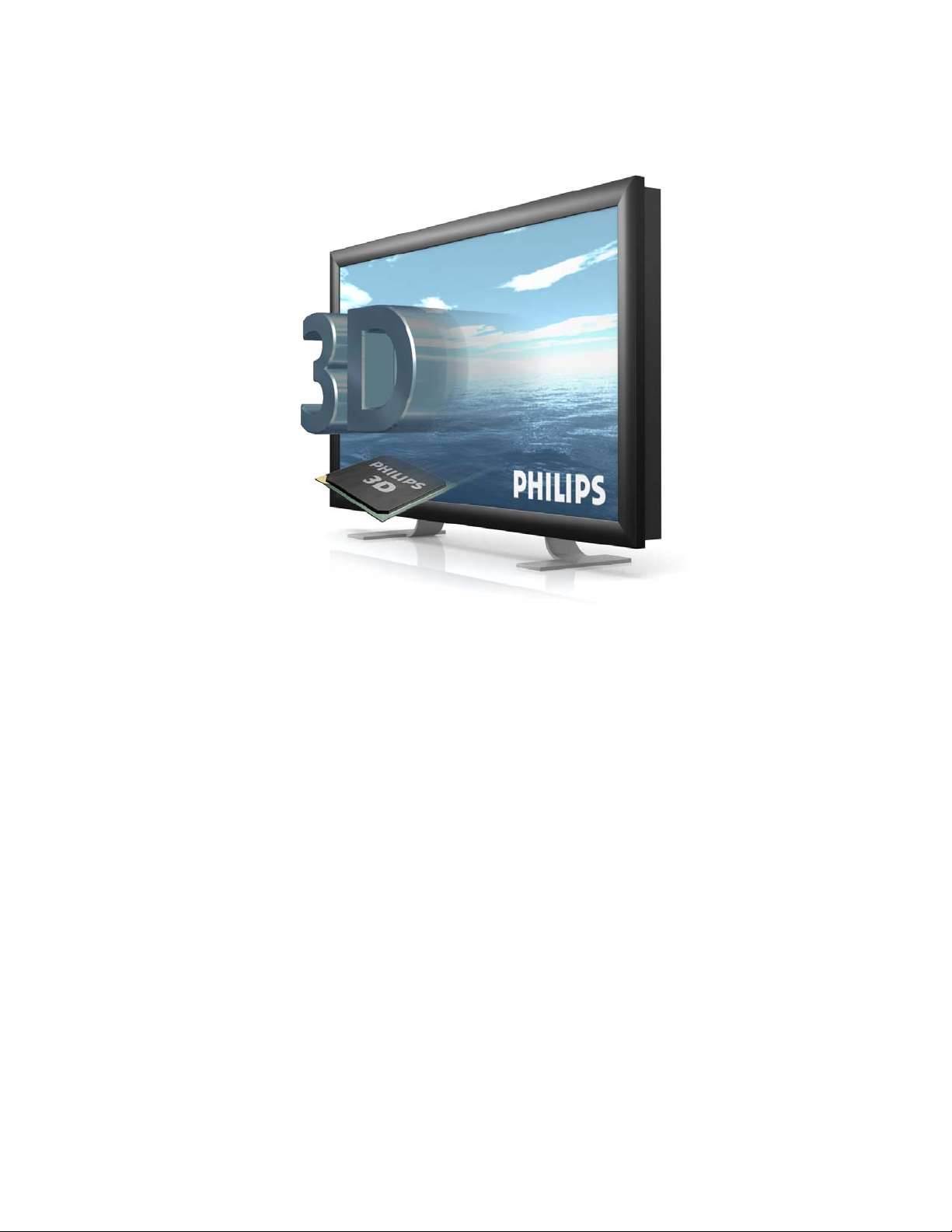
42-inch 3D-Intelligent Display
42-3D6C01/00
42-3D6W01/00
42-3D6C02/00
42-3D6W02/00
User Manual
Philips 3D Solutions
Warning this is a class A product. In a domestic
environment this product may cause radio interference
in which case the user may be required to take
adequate measures.
Safety Instructions for 3D display
Read and follow these instructions:
1. This product must be earthed.
2. The mains plug or appliance inlet is used as the disconnect device and
should be easily accessible.
3. Use only an approved power cord or interconnection cable.
4. Unplug the product if you are not going to use it for a long period of time.
5. Unplug the product if you need to clean it, use a slightly damp cloth. Never
use alcohol, solvents or ammonia-based liquids.
6. Refer all servicing to qualified service personnel
7. Do not block any ventilation holes.
8. To avoid electric shock, do not expose to rain or excessive moisture.
9. Do not store or use the product in locations exposed to excessive heat,
direct sunlight, extreme cold or in dusty environments.
10. Avoid moving the product between locations with large temperature
differences.
11. Choose a location within the following temperature and humidity ranges.
• Temperature: 0- 35°C
• Humidity : 20-80% RH
12. Avoid hitting or dropping during operation and transportation.

Mounting
The display can be placed on a table stand or wall-mounted. The table stand is
supplied as standard; the mounting bracket can be purchased separately. This
bracket can also be used as an adapter in combination with universal wall
supports, ceiling supports or universal floor stands (e.g. Vogel’s Professional).
Fitting the table stand
Only use the stand supplied with the set, making sure that the fasteners are
properly tightened. Never use a makeshift stand, or legs fixed using wood screws.
Using the mounting bracket
The standard VESA mount holes on the mounting bracket allow the user to install
the Philips 3D display on any VESA MIS-E compatible wall support, ceiling
support or floor stand.
Important: Use a VESA MIS-E compatible support suitable for the weight of this
3D Display.
Always secure the mounting bracket to the display using 4 screws. This helps
avoid potentially dangerous situations when lifting the display out of the mounting
bracket.
Positioning the display
For the best results, choose a place where there is no direct light shining onto the
screen, and which is some distance away from radiators or other sources of heat.
Leave a space of at least 10 cm all around the display for ventilation, making sure
that curtains, cupboards etc. cannot obstruct the airflow through the ventilation
apertures. The display is intended for use in a public places only and should
never be operated or stored in excessively hot or humid conditions.
Avertissement – Ce produit est un produit de classe A.
Dans un environnement domestique, ce produit peut
causer un brouillage radioélectrique. L’utilisateur
pourrait avoir à prendre des mesures appropriées à
cet égard.
Instructions de sécurité pour l’écran 3D
Prière de lire et respecter les instructions suivantes :
1. Cet appareil doit être connecté à la terre.
2. La fiche secteur ou la prise d’entrée de l'appareil est utilisée comme
dispositif de débranchement et doit être facilement accessible.
3. Utilisez uniquement un cordon d’alimentation ou un câble d’interconnexion
approuvé.
4. Déconnectez l’appareil si vous ne l’utilisez pas pendant une période
prolongée.
5. Déconnectez l’appareil pour le nettoyer ; utilisez un chiffon légèrement
humidifié. Ne jamais utiliser de l’alcool, des solvants ou des produits à
base d’ammoniac.
6. Confiez les opérations d’entretien au personnel d’entretien qualifié.
7. Ne pas bloquer les orifices d’aération.
8. Afin d’éviter tout choc électrique, ne pas exposer l’appareil à la pluie, ni à
un taux d’humidité excessif.
9. Ne pas entreposer ni utiliser l’appareil dans des lieux poussiéreux ou
exposés à une chaleur excessive, aux rayons du soleil ou à des
températures excessivement basses.
10. Évitez de transporter l’appareil entre deux endroits entre lesquels il y a une
grande différence de température.
11. Veillez à ce que le lieu d’entreposage ou d’utilisation ait les
caractéristiques de température et de taux d’humidité suivantes :
• Température: 0-35°C
• Humidité relative : 20-80%
12. Évitez les chocs ou la chute de l’appareil pendant son utilisation ou
pendant le transport.

Montage
L’écran peut être placé sur un support de table ou monté au mur. Le support de
table est fourni avec l’appareil et le support de montage au mur est vendu
séparément. Ce support peut également servir d’adaptateur combiné à un support
de plafond ou encore à un support mural ou de plancher de type universel (par ex.,
modèle Vogel Professional).
Installation du support de table
N’utilisez que le support fourni avec l’ensemble en vous assurant de bien serrer les
dispositifs d'attache. N’utilisez jamais de support improvisé ni de pattes fixées à
l'aide de vis à bois.
Utilisation du support de montage
Les trous de montage VESA standards sur le support de montage permettent à
l’utilisateur d’installer l’écran Philips 3D sur tout support conforme à la norme VESA
MIS-E, qu’il soit de type mural, de plafond ou de plancher.
Important : Utilisez un support conforme à la norme VESA MIS-E qui convient au
poids de cet écran 3D.
Assurez-vous de fixer le support de montage à l’écran au moyen de 4 vis. Vous
éviterez ainsi toute situation dangereuse en soulevant l'écran hors du support de
montage.
Positionnement de l’écran
Pour obtenir de meilleurs résultats, choisissez un endroit éloigné des appareils de
chauffage et autres appareils dégageant de la chaleur et où aucune lumière directe
n’est réfléchie sur l’écran. Laissez un espace d’au moins 10 cm tout autour de
l’écran pour permettre une aération adéquate, en vous assurant que les rideaux,
armoires et autres n’empêchent pas l’air de circuler par les grilles d’aération.
L’écran a été conçu pour fonctionner dans des environnements publics et ne
devrait jamais être utilisé ou rangé dans un endroit extrêmement chaud ou humide.
Document Information
Info Content
Title 42 inch 3D Display, User Manual (9922 159 01 73 1 090401)
Date 01 April 2009
Security The material and the information contained herein are
proprietary to Philips 3D Solutions. Copying, reproduction,
adaptation, modification or dissemination in whole or part is not
permitted without the prior written consent of Philips 3D
Solutions.
Contact http://www.philips.com/3dsolutions

Display User Manual
3D Solutions
Table of Contents
1 Introduction ............................................................................................................................................................................. 8
2 Product features ................................................................................................................................................................... 9
2.1 Global product features ........................................................................................................................................... 9
2.2 Technical aspects and details ............................................................................................................................. 10
2.3 Cosmetic specifications ......................................................................................................................................... 11
3 Scope of supply, Set up and mounting ..................................................................................................................... 14
3.1 Scope of Supply ....................................................................................................................................................... 14
3.2 Image retention ......................................................................................................................................................... 14
3.3 Connecting the display .......................................................................................................................................... 15
3.4 Cleaning instructions .............................................................................................................................................. 16
3.5 Disposal of your old product ................................................................................................................................ 17
4 Software installation .......................................................................................................................................................... 18
4.1 Minimum PC requirements .................................................................................................................................. 18
4.2 Prepare PC ................................................................................................................................................................. 18
5 Environmental .....................................................................................................................................................................
6 Interfaces ............................................................................................................................................................................... 20
6.1 DVI-in ............................................................................................................................................................................ 20
6.2 LED ................................................................................................................................................................................ 20
7 Trademarks, Copyrights and disclaimer ................................................................................................................... 21
8 Mounting bracket ................................................................................................................................................................ 22
9 References ........................................................................................................................................................................... 25
19
01 April 2009
©2009 Philips Electronics Nederland B.V. 7 of 25

Display User Manual
3D Solutions
1 Introduction
The 42-inch 3D display from Philips 3D Solutions offers state-of-the-art lenticular lens design
creating a variety of distinct autostereoscopic views. By this the viewer will benefit from the
multi-user experience along with a large comfort zone. The 42-inch 3D display is specifically
designed for a wide range of applications such as digital signage and information provision.
The display is featuring superior lens design and 3D rendering relying on proven, highly
optimized and accurate manufacturing processes. The lens design minimizes cross talk,
creating highly distinct views. The 42-3D6C01/00 and 42-3D6C02/00 are designed for optimal
viewing comfort. The 42-3D6W01/00 and 42-3D6W02/00 are designed for maximum WOW
viewing experience.
The display’s 2D-plus-depth rendering interface is open, allowing maximum flexibility. No
matter what sort of Philips 3D Solutions display is used, the content does not need
regeneration. What’s more, the rendering hardware sits inside the display, allowing for
maximum optimisation of the optical system by embedded processing.
Provided with the 42-inch 3D display are the 3DS Media Player and the Display Control Tool.
The Display Control Tool can be used to set all kinds of visualisation parameters for the 3D
display; examples are the WOW offset, the WOW range, the contrast, and the brightness. The
3DS Media Player is used for play-out for the Philips 3D Solutions 3D displays. It takes care
that the display switches to 3D mode with the appropriate 3D visualization settings.
A digital version of the 3D Display User Manual can be downloaded from our website:
www.philips.com/3dsolutions
.
01 April 2009
8 of 25 ©2009 Philips Electronics Nederland B.V.

Display User Manual
2 Product features
2.1 Global product features
Multi-view Lenticular Display
o 9 view autostereoscopic 3D display
o Non-switchable lenticular technology
o Optimal viewing distance: 3 meters (10 feet).
o Wide comfort zone for 3D perception
o Full brightness, full contrast
o 2D-plus-Depth or Declipse input in 3D mode
o Protective plate at the front side of the display
Advanced display signal processing engine
o Integrated 3D display processing hardware
o Open 3D data interface
o 2D-plus-Depth converted to 9 different views and interwoven into a 3D image
o Rendering algorithm is tuned for lenticular optical behaviour
o Two modes:
• 3D rendering mode
• 2D transparent mode with picture quality improvement filter
Connectivity
o Display control via DDC/CI channel; no additional RS232 cable needed
o AC switch
o A LED indicates ‘power on’ and ‘standby’ mode
3D Solutions
1
1
For an elaborate explanation on the display interface formats see the ‘3D Interface Specifications white paper’ document. It can be downloaded from the Documents section on
http://www.philips.com/3dsolutions
.
01 April 2009
©2009 Philips Electronics Nederland B.V. 9 of 25

Display User Manual
3D Solutions
2.2 Technical aspects and details
Group Item 42-3D #
LCD
panel
Resolution 1920 x RGB x 1080
Pixel pitch 0.4845 mm x 0.4845 mm
Effective viewing area 930.24 mm x 523.26 mm
Size 42’’
Contrast Ratio 1500:1
Aspect Ratio 16:9
Brightness 500 cd/m
Response time 8 ms (gray-to-gray)
Refresh rate 60 fps
Display colors 16.7 M (8 bits RGB)
White chromaticity Wx: 0.280 Wy: 0.285 (at 10500 K)
Physical Weight (including table
Type TFT LCD
42-3D6C #: 32 kg
stand)
42-3D6W #: 35 kg
2
Dimensions (WxHxD) 1017 x 610 x 128 mm
Package dimensions
(WxHxD)
Installation Table stand (included) wall, or ceiling
Power Consumption 230 W
Power Consumption
standby
Operating temperature 0 - 35 °C
Relative humidity 20 % to 80 %
System MTBF 50K hrs
Installation angle 0 - 10° from vertical
Interface Connector DVI-D single link
Voltage 110 – 230 V, 50 – 60 Hz
1176 x 791 x 318 mm
mounting bracket or free-standing (optional)
2.5 W
01 April 2009
10 of 25 ©2009 Philips Electronics Nederland B.V.

Display User Manual
jor
A
jor
2.3 Cosmetic specifications
2.3.1 Description
This specification standard is applicable to:
3D-displays supplied by Philips 3D Solutions.
2.3.2 Environmental conditions of inspection
3D Solutions
The environmental conditions and visual inspection shall be conducted as below.
Ambient temperature in the range 15-25 [
Humidity in the range 25-75 [%RH].
The functional inspection distance of the monitor (measured between the monitor and the
inspector’s sight) should be at least 3.0 [m].
The maximal viewing angle relative from the normal direction of the module/monitor is
specified according to ±Y degree to the front surface of the display in vertical direction, and ±X
degree to the front surface of the display in horizontal direction. The values below are the
following: X = 15, Y = 45.
Ambient illumination:
External appearance inspection in the range 400-600 [Lux].
Light on inspection in the range 100-200 [Lux].
o
C].
2.3.3 Classification of defects
The defects are classified as major and minor defects. The definition of defects is described as
follows:
Major defect:
The defect may cause functional failure, or reduce the usability of the product for its purpose.
For example: electrical failure, deformation, etc.
Minor defect:
The defect does not reduce the usability of the product for its purpose. For example: dot
defect, etc.
The judgement of the major and minor defects shall be according to the table with
classification of defects below.
Inspection item Description Defect type
Vertical line Abnormal line appears in vertical
direction.
Horizontal line Abnormal line appears in horizontal
direction.
Cross line Abnormal cross line appears in display. Major
No display No signal output in display.Ma
Irregular display
Dot defect Bright dot, dark dot or dot adjacent
©2009 Philips Electronics Nederland B.V. 11 of 25
bnormal signal outputs in display.Ma
appear in display.
Major
Major
Minor
01 April 2009

Display User Manual
3D Solutions
Foreign material Foreign material appears in display Minor
2.3.4 Inspection Criteria
Definition of dot defect:
If the size of a dot defect is larger than 0.5 times a single pixel, it can be regarded as one dot
defect
Bright dot: Dot appears bright and the size is fixed in a black pattern.
Dark dot: Dot appears dark and the size is fixed in pure red, green and blue pattern.
2.3.4.1 Display defects
The size of a circular area is defined by the average of the size along the horizontal axis (=a)
and the vertical axis (=b), i.e. D=(a+b)/2. The size of a lint/scratch is defined by its with (=W)
and its length (=L).
Item 3D-display Maximum
tolerance
Bright dot Random N ≤ 3
2 dots adjacent N ≤ 1
3 dots adjacent or more N ≤ 0
Dark dot
Total bright and dark dots N ≤ 12
Backlight Break down Not permitted
Connector Oxidized/rusty connector not acceptable
Item protective plate Maximum tolerance
Protective plate
scratches
Item 3D-display Maximum tolerance
LED function See paragraph
Cosmetic
profiles
Outside and
connectors
Disclaimer will be printed on bag sticker and included in this manual
Please be aware that the protective plate in front of this display is sensitive
for scratching during cleaning. This is caused by hard particles (like sand)
that might be present in the cloth used and/or the cleaning fluid.
Small backlight intensity variations can occur in dark backgrounds
Random N ≤ 12
2 dots adjacent N ≤ 2
3 dots adjacent or more
Minimum distance between dark
N ≤ 1
L ≥ 15 [mm]
dots
0.15 < W ≤ 0.25 [mm], 0.3 < L ≤ 10.0 [mm], N ≤ 7
Failure not acceptable
7.2
Scratches
0.05 < W ≤ 0.15 [mm], 0.3 < L ≤ 2.0
[mm], N ≤ 7
Sharp edges Not allowable.
Cracks and
Rust
Not acceptable under any
circumstances.
01 April 2009
12 of 25 ©2009 Philips Electronics Nederland B.V.

Display User Manual
y
3D Solutions
Discoloration of the active area circumference can occur and should be
treated as normal and will not change the functional performance of the 3D
intelligent display.
Philips 3D Solutions is not responsible for a poor performance due to a not
optimal signal input according to display timing recommendation below
Advanced Timing
Horizontal
pixels
Front porch 15
Back porch 48 Scan rate 67.02 kHz
Sync
Vertical
lines
Front porch 5 Sync width 5
Back porch 26 Refresh
Sync
Pixel clock 145.30
Sync width 48
2
+ Active lines 1920
polarity
60.054 Hz
rate
polarit
+ Active
pixels
1080
MHz
Signals must comply with the
following DVI standard:Digital
Visual Interface DVI
Digital Display Working Group
Revision 1.0; April 02, 1999
01 April 2009
©2009 Philips Electronics Nederland B.V. 13 of 25

Display User Manual
3D Solutions
3 Scope of supply, Set up and mounting
3.1 Scope of Supply
The contents of the box:
o Display 42-3D #
o Table stand
o 3 Mains cords (USA, EU and UK)
o DVI cable
o CD ROM with:
Display Control Tool
3DS Media Player
User manuals
3D Sample content
o Printed version of the Display user manual (this manual)
o Cardboard box with cushions
The following items can be purchased separately:
o Mounting bracket (Article code: 42-WM)
3.2 Image retention
IMPORTANT: Always display alternating content with your application. If a still image in high
contrast remains on the screen for an extended period of time, it may leave an 'after-image' or
'ghost image' on the front of the screen. This is a well-known phenomenon, caused by the
shortcomings inherent in the LCD technology. Please note that the after-image symptom
cannot be repaired and is not covered under warranty.
01 April 2009
14 of 25 ©2009 Philips Electronics Nederland B.V.

Display User Manual
3.3 Connecting the display
NEVER (dis)connect DVI when your PC or Display is on.
2D monitor
(optional)
DVI cable
PC
DVI cable
3D Solutions
3D Display
Power cord
A second 2D display may be connected to the PC. Only use a DVI cable and graphics card
that is compliant with the DVI standard (see reference to DVI standard in section 9).
The picture below show the DVI-connector and power connector on the back of the display
1
2
Make sure the PC and Display are switched off!
1. Connect the PC via the DVI cable to the DVI connecter.
2. Connect the power cord.
01 April 2009
©2009 Philips Electronics Nederland B.V. 15 of 25

Display User Manual
3D Solutions
3.4 Cleaning instructions
Before cleaning the display, disconnect the power cord and DVI cable.
It is preferable to clean the front of the display with the cleaning products listed in the table
below.
To clean we recommend:
cleaning materials e.g. soft cotton cloth
window leather
Aqueous solution, neutral and weakly
alkaline window cleaner without
additives of abrasive substances:
Permitted portion of ammonia < 5
Vol-%, as well as water soluble
organic solvents < 5 Vol-%.
Do not use for cleaning:
alkaline lyes e.g. durd soap, certain textile detergents
lyes e.g. toilet cleaner
acids e.g. hydrochloric acid, vinegar, lemon
decalcification agent e.g. citric acid
degreasing agent e.g. acetone, methylene chloride,
Strong ammonia detergents e.g. Toilet cleaner
chlorine or Hypochloride detergents e.g. Chavel water, Domestos
solvents e.g. Ethyl alcohol, Isopropyl alcohol,
coarse millinery e.g. abrasive, steel wool, sponge with
Other Electrolube ASC, REF ASC250ml
As an alternative, clean the front of the display with a solution of soft soap (e.g. liquid hand
soap) and tepid water, using a soft cloth or sponge.
The rest of the display can be cleaned with a dry cloth.
e.g. Flux
Ajax
trichloroethylene, petrol
alcohol, acetone, trichloroethylene,
benzene, hexane, petrol
abrasives, blades cloth with thread
made of steel, hard cloth or paper
tissue
01 April 2009
16 of 25 ©2009 Philips Electronics Nederland B.V.

Display User Manual
3D Solutions
3.5 Disposal of your old product
Your product is designed and manufactured with high quality materials and components,
which can be recycled and reused.
Please act according to your local rules and do not dispose of your old products with normal
household waste. The correct disposal of your old product will help prevent potential negative
consequences for the environment and human health.
When this crossed-out wheeled bin symbol is attached to a product it means
the product is covered by the European Directive 2002/96/EC
Please inform yourself about the local separate collection system for electrical
and electronic products.
01 April 2009
©2009 Philips Electronics Nederland B.V. 17 of 25

Display User Manual
3D Solutions
4 Software installation
This chapter contains the prerequisites for the PC hardware and the operating system for the
software. First, check whether your PC complies with the requirements that are given in the
next sections. Then follow the installation instructions, where you will be guided step by step
through the software installation procedure.
4.1 Minimum PC requirements
The PC must comply with the following requirements:
o Pentium 4, ≥ 3 GHz or Dual core ≥ 1.7 GHz
o ≥ 512 MB internal memory for Windows XP, ≥ 1024 MB internal memory for Windows
Vista
o 7200 rpm hard disk with 8 Mbyte cache (minimal sustained throughput 10 MB/s)
o DVD ROM player
o Graphics card:
o based on NVIDIA for example 7600 or 8600 chipsets,
o or based on NVIDIA Quadro for example FX1400 (windows XP only),
o or based on ATI for example X1650 (Windows XP only).
o Windows XP SP2 or Windows Vista (see above for restrictions concerning graphics
cards)
4.2 Prepare PC
Make sure that the following software is installed on the PC before connecting the 3D Display
to the PC:
o Windows XP (upgraded to Service Pack 2) or Windows Vista
o NVIDIA Display driver or ATI Driver (Windows XP only)
01 April 2009
18 of 25 ©2009 Philips Electronics Nederland B.V.

Display User Manual
5 Environmental
Condition Operating Shipping / storage
Temperature
Humidity 20 % - 80 %
Air pressure 600 – 1100 mBar 300 – 1100 mBar
The display is only used indoor.
0 °C to 35 °C -20 °C to 60 °C
0% - 95 %
No condensation
No condensation
3D Solutions
01 April 2009
©2009 Philips Electronics Nederland B.V. 19 of 25

Display User Manual
3D Solutions
6 Interfaces
6.1 DVI-in
Pi
n
1 T.M.D.S.
2 T.M.D.S.
3 T.M.D.S.
4 No
5 No
6 DDC
7 DDC Data 15 Ground
8 No
The DDC Clock and the DDC data are used by the Display Control Tool to control depth and
colour settings in the display.
Signal Pi
n
9 T.M.D.S.
Data2-
10 T.M.D.S.
Data2+
11 T.M.D.S.
Data2/4
Shield
12 No
connect
13 No
connect
14
Clock
16 Hot Plug
connect
Signal Pi
n
17 T.M.D.S.
Data1-
18 T.M.D.S.
Data1+
19 T.M.D.S.Da
Data1/3
Shield
20
connect
21
connect
+5V
Power
(for +5V)
Detect
22 T.M.D.S.
23
24 T.M.D.S.
Signal
Data0-
Data0+
ta0/5
Shield
No connect
No connect
Clock
Shield
T.M.D.S.
Clock+
Clock-
6.2 LED
LED Color Status
Red Display is in standby mode. No DVI clock is present.
Green Display on
01 April 2009
20 of 25 ©2009 Philips Electronics Nederland B.V.

Display User Manual
3D Solutions
7 Trademarks, Copyrights and disclaimer
Specifications are subject to change without notice.
Trademarks are the property of Koninklijke Philips Electronics N.V. or their respective owners.
2009© Koninklijke Philips Electronics N.V. All rights reserved.
01 April 2009
©2009 Philips Electronics Nederland B.V. 21 of 25

Display User Manual
3D Solutions
8 Mounting bracket
The mounting bracket is not supplied as standard with the 3D Display. It must be purchased
separately with article code: 42-WM.
Installation instructions are supplied with the mounting bracket. Please read these carefully
and act accordingly. This chapter contains the dimensions of the mounting bracket.
01 April 2009
22 of 25 ©2009 Philips Electronics Nederland B.V.

Display User Manual
Hole pattern on mounting bracket:
3D Solutions
01 April 2009
©2009 Philips Electronics Nederland B.V. 23 of 25

Display User Manual
3D Solutions
Location of mounting bracket relative to display (rear view).
01 April 2009
24 of 25 ©2009 Philips Electronics Nederland B.V.

Display User Manual
9 References
The following references are not normative but informative.
Description
VESA Display data channel standard;
Version 3; December 15, 1997
VESA Display data channel command interface (DDC/CI) standard;
Version 1; August 14, 1998
Digital Visual Interface DVI;
Digital Display Working Group;
Revision 1.0; April 02, 1999
VESA enhanced extended display identification data standard;
Release A, Revision 1;
February 9, 2000
ITU-R BT.709.4; Parameter values for HDTV standards for production and
international programme exchange;
- 0 – 0 – 0 – 0 – 0 -
3D Solutions
01 April 2009
©2009 Philips Electronics Nederland B.V. 25 of 25
 Loading...