

Philips BDL4221V/00, BDL4221V/27, 420WN6QS/93, BDL4221VS/00, 420WN6QS/97 Service Manual
Horizontal frequencies
30 - 63kHz
Service
Service
Service
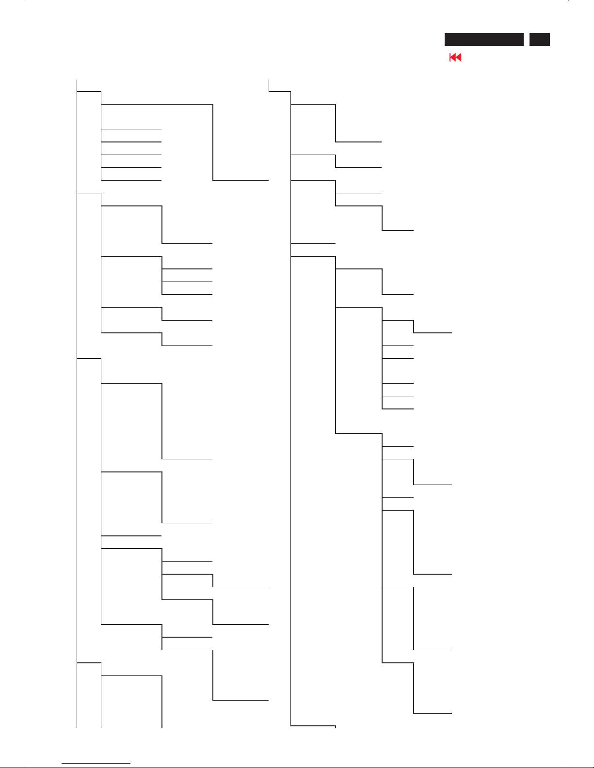
TABLE OF CONTENTS
Published by BCU Monitors Printed in suzhou Copyright reserved Subject to modification F May .23 2006
Description Page
Important Safety Notice---------------------------------- 2
Technical Data/Installation----------------------------3~7
On-Screen Display------------------------------------8~11
Aging Mode/OSD LOCK/UNLOCK--------------------12
Trouble shooting-------------------------------------15~17
Failure Mode Of Panel-----------------------------------18
Factory Mode/Warning message-----------------13~14
Safety Test Requirements ------------------------------19
Mechanical Instructions----------------------------20~21
Electrical Instructions-------------------------------22~25
Display adjustment----------------------------------26~27
DDC DATA/Instructions-----------------------------28~36
ISP Instructions --------------------------------------37~38
Block Diagram---------------------------------------------39
Description Page
Scaler Diagram--------------------------------------40~55
Scaler Board C.B.A---------------------------------56~57
Power Diagram/C.B.A -----------------------------58~60
IR&Control Diagram/C.B.A -----------------------61~62
DSUB Diagram/C.B.A------------------------------63~65
Tuner Diagram/C.B.A------------------------------66~68
Exploded View -------------------------------------------69
Recommended/Spare parts list -----------------70~75
Circuit description---------------------------------------76
Repair Tips-------------------------------------------77~78
General product specification------------------79~123
Different Parts List-------------------------------------124
Updated for 420WN6QS-----------------------125~126
Revision List--------------------------------------------127
REFER TO BACK COVER FOR IMPORTANT SAFETY GUIDELINES
CAUTION: USE A SEPARATE ISOLATION TRANSFORMER FOR THIS UNIT WHEN SERVICING.
ANY PERSON ATTEMPTING TO SERVICE THIS CHASSIS MUST FAMILIARIZE HIMSELF WITH THE CHASSIS
AND BE AWARE OF THE NECESSARY SAFETY PRECAUTIONS TO BE USED WHEN SERVICING ELECTRONIC
EQUIPMENT CONTAINING HIGH VOLTAGES.
SAFETY NOTICE
GB
3138 106 10490
BDL 42" LCD Monitor/TV
BDL4221V/00
BDL4221V/27
BDL4221VS/00
420WN6QS/93
420WN6QS/97
Important Safety Notice
2
420WN6 LCD TV
Go to cover page
Proper service and repair isimportant to the safe, reliable
operation of all HPConsumer Electronics Company**
Equipment. The service procedures recommended by HP and
described in this service manual are effective methods of
performing service operations. Some ofthese service
operations require the use of tools specially designed for the
purpose. The special tools should be used when and as
recommended.
It is important to note that this manual contains various
CAUTIONS and NOTICES which should be carefully read in
order to minimize the risk of personal injury to service
personnel. The possibility exists that improper service
methods may damage the equipment. It is also important to
understand that these CAUTIONS and NOTICES ARE NOT
EXHAUSTIVE. HP could not possibly know, evaluate and
advise the service trade of all conceivable ways in which
service might be done or of the possible hazardous
consequences of each way. Consequently, HP has not
undertaken any such broad evaluation. Accordingly, a
servicer who uses a service procedure or tool which is not
recommended by HP must first satisfy himself thoroughly that
neither his safety nor the safe operation of the equipment will
be jeopardized by the service method selected.
* * Hereafter throughout this manual, HP Consumer
Electronics Company will bereferred to as HP.
Critical components having special safety characteristics are
identified with a bythe Ref. No. inthe parts list and
enclosed within a broken line*
(where several critical components are grouped in one area)
along with the safety symbol on the schematics or
exploded views.
Use of substitute replacement parts which do not have the
same specified safety characteristics may create shock, fire,
or other hazards.
Under no circumstances should the original design be
modified or altered without written permission from Philips.
Philips assumes no liability, express or implied, arising out of
any unauthorized modification of design.
Servicer assumes all liability.
*BrokenLine
WARNING
Take care during handling the LCD module with backlight
unit
- Must mount the moduleusing mounting holes arranged infour
corners.
- Do not press onthe panel, edge of theframe strongly or electric
shock as this will result in damage to the screen.
- Do not scratch orpress on the panel withany sharp objects, such
as pencil or pen asthis may result in damage to the panel.
- Protect the module fromthe ESD as it maydamage the electronic
circuit (C-MOS).
- Make certain that treatment person s body are grounded through
wrist band.
- Do not leave themodule in high temperature andin areas of high
humidity for a long time.
- Avoid contact with water as it may ashort circuit within the module.
- If the surface ofpanel become dirty, please wipe it off with a soft
material. (Cleaning with a dirty or rough cloth may damage the
panel.)
FOR PRODUCTS CONTAINING LASER :
DANGER- Invisible laser radiation when open.
AVOID DIRECT EXPOSURE TO BEAM.
CAUTION- Use of controls or adjustments or
performance of procedures other than
those specified herein may result in
hazardous radiation exposure.
CAUTION- The use of optical instruments with this
product will increase eye hazard.
TO ENSURE THE CONTINUED RELIABILITY OF THIS
PRODUCT, USE ONLY ORIGINAL MANUFACTURER'S
REPLACEMENT PARTS, WHICH ARE LISTED WITH THEIR PART
NUMBERS IN THE PARTS LIST SECTION OF THIS
SERVICE MANUAL.
3
Technical Data
420WN6 LCD TV
Go to cover page
1. General
1.1. Product description
This 42 LCD TV Monitor is specified as a display peripheral with PC
analog video signal input and includes TV/ DTV function with 42 TFT
LCD display.
Horizontal scan range is 30~63KHz and refresh range is 50~75 Hz.
This scan range allows it to display resolution up to 1366x768
non-interlaced at 60 Hz refresh rate. The image can be adjusted
through OSD control; these adjustments can be stored on a board
memory including 12 factory pre-set modes.
1.2 Destination : WE (PAL B/G/D/K /I ; SECAM L /L? )
1.3 B asic data
1.3.1 LCD panel
1.3.1.1 LPL Panel
Type NO : LC420W02 B6 (Supplier LPL)
Display area(mm) : 930.25mm x 523.01mm
Number of Pixels : 1366(H) x 768(V)
Pitch ( mm ) : 0.227mm(H) x 0.681mum(V)
Color pixel arrangement : RGB vertical stripe
Display operating mode : Normally black
Color depth : 16,777,216 colors ( 8 bits)
Brightness (cd/m^2) : 500(Center 1 points, Typ.)
Viewing angle(CR>10) : Viewing angle free(R/L 178(Typ.),
U/D 178(Typ.))
Surface treatment : Hard coating(3H),Anti-glare treatment of
the front polarize
Electrical interface : LVDS
Response Time (ms, Typ) : TrR:8,TrD:10(Gray to Gray)
Contrastratio :Typical1100:1withAI
Outline Dimension : 1006 mm(H) x 610 mm(V) x 56(D) mm (Typ.)
Module weight (g) : 11,800(Typ.)
Backlight : 20 CCFL
1.3.2. Power supply
AC-input : 90V ~ 264VAC,50/60±2Hz
Power consumption : 140W/Typ(at PC mode),220W/Typ
(atTVmode).
Power cord length : 1.8M
Power cord type : European type and UK type
Power indicator : LED (On: Blue ,Sleeping mode: Amber )
Auto power saving : < 5W
"
"
1.3.3. Horizontal scan : 30 ~ 63KHz
1.3.4. Vertical scan : 50 ~ 75 Hz
1.3.5. Input signals
1.3.5.1 PC Signal type
a. Analog Video : 15 pin D-Sub
0.7 Vp-p linear, positive polarity and
separate Sync ( TTL level, positive or negative polarity )
b. Audio signal : Mini-jack audio input
c. Signal source : Pattern generator format refer to the SPEC
d. Reference generator : CHROMA 2135 or 2250
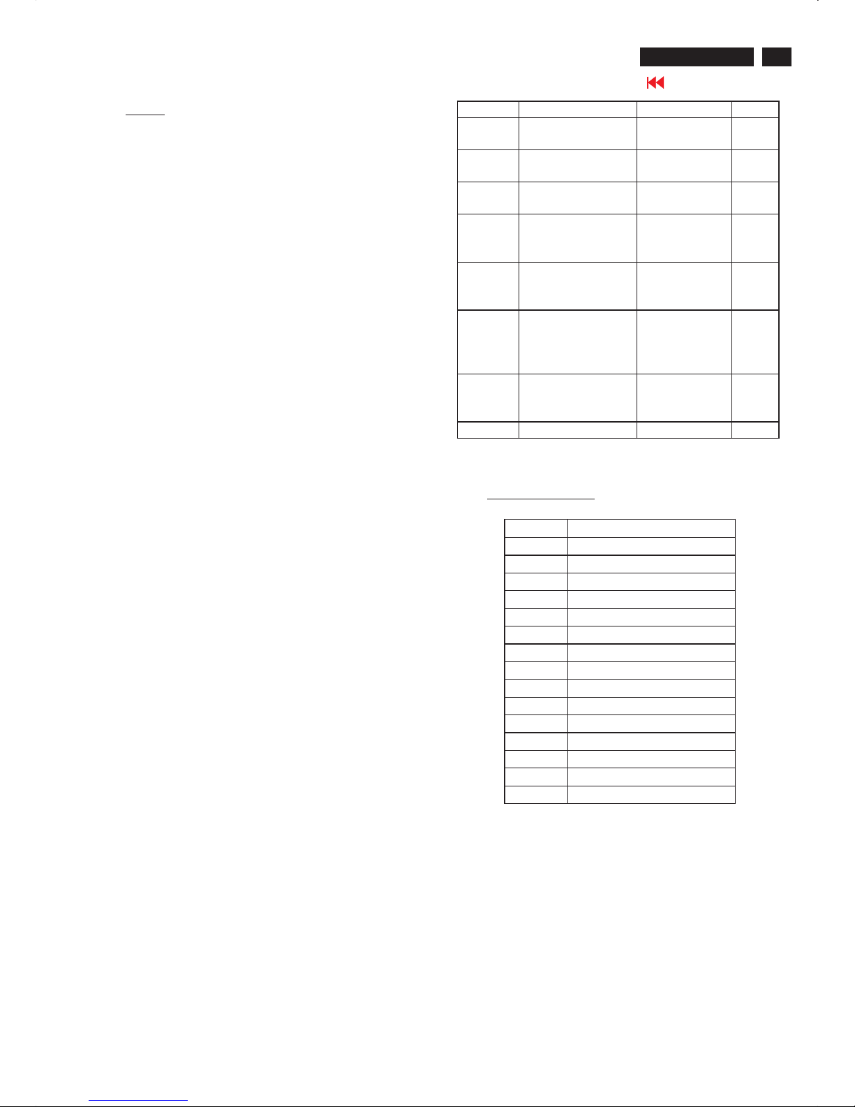
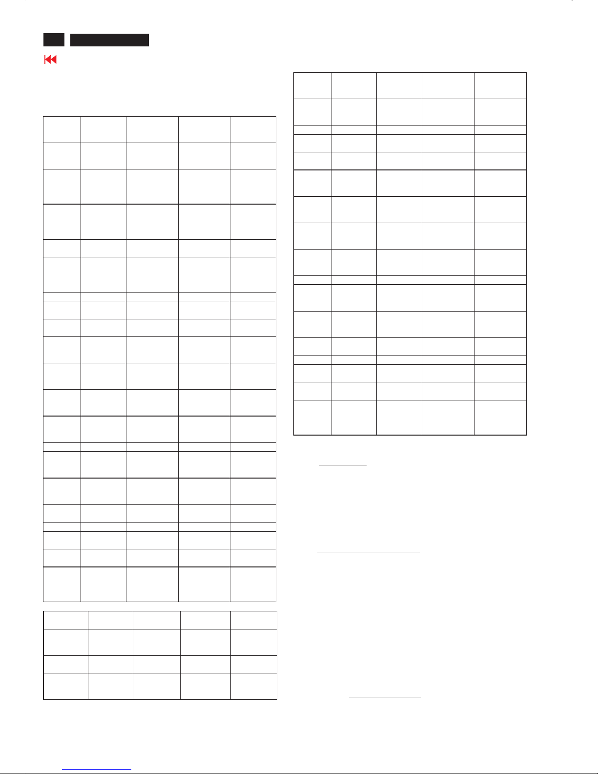
1.3.5.2 TV Signal type: (Video Model : without RF signal input)
Signal type Video signal Audio signal Remark
Composite Input / Output
SCART connector
Input / output, L /R
SCART connector
R,G,B Input
SCART connector
Input
SCART connector
CVBS Input
RCA connector, Yellow
Share with S-Video
S-Video Input
S-terminal, Black
Input, L/R
RCA connector, white,
Red
Component
Y, Pb, Pr
Input
RCA connector,
Green, Blue, Red
Input, L/R
RCA connector, white,
Red
CVBS Output Output ( from CVBS )
RCA connector, Yellow
Output ( from CVBS ),
L/R
RCA connector, white,
Red
DVI IN Digital TV signal support
HDCP
DVI connector
Input, VGA audio in
RF Signal Antenna input or Cable input * Option
1.3.6 PC input connectors
A. PC Analog Video input with D-SUB connector
D-SUB Pin assignment
Signal interface
1.8M 15 Pins, D-SUB male.
Sync polarity
-Hori. sync positive/negative
-Vert. sync positive/negative
PIN No. SIGNAL b(PC)
1Red
2Green
3Blue
4GND
5GND
6RedGND
7GreenGND
8BlueGND
9 +5V (Supply from PC)
10 Sync GND
11 GND
12 Bi-directional data
13 H-sync
14 V-sync
15 Data clock

4
420WN6 LCD TV
Go to cover page
B. Output analog D-sub connector pin assignment
PIN No. SIGNAL
1 Red_OUT
2 Green_OUT
3 Blue_OUT
4GND
5GND
6RedGND
7GreenGND
8BlueGND
9GND
10 Sync GND
11 GND
12 GND
13 H-sync_OUT
14 V-sync_OUT
15 GND
C. DVI-D : Pin assignment (for PC DVI and Video HDCP)
Signal interface
- 1.8M 24 Pins, DVI-D male.
Signal type - Digital interface with 4 channels TMDS signal
(2) PC Audio input with 3.5 Mini stereo jack
Specification
Audio L/R input
-Nominal :0.5Vrms.
- Maximum : 1.5 V rms.
-Impedance > 10 k ? .
1.3.7 TV video input /output connectors
(1 ) TV Tu ner with RF connector (Option)
TV Input from Aerial or Cable
Specification
Pin No. Description
1RX2-
2RX2+
3GND
4GND
5GND
6 DDC clock
7 DDC data
8GND
9RX1-
10 RX1+
11 GND
12 GND
13 GND
14 +5V
15 GND
16 +5V
17 RX0-
18 RX0+
19 GND
20 GND
21 GND
22 GND
23 RXC+
24 RXC-
-AerialorCable
- Impedance 75 ohm.
(2) HD / Com ponent Y Pb Pr with RCA connector ( Video , Audio input )
Specification
Video - Y : 700mV, Pb, Pr, : ± 350mV,
- Impedance : 75ohm
Audio: L/R input
- Nominal : 0.5 V rms.
- Maximum : 1.5 V rms.
- Impedance > 10 kohm.
Note : the input will be overloaded when the signal > 1.5 V rms.
(3) S-Video with S terminal (Video, Audio input)
Specification
Video - Y : 1Vpp , C : 300 mV pp
- Impedance : 75ohm.
Audio L/R input (share with Composite Audio input)
-Nominal :0.5Vrms.
- Maximum : 1.5 V rms.
- Impedance > 10 kohm.
Note : the input will be overloaded when the signal > 1.5 V rms.
(4) CVBS inpu t with RCA Jack (Video, Audio input)
Specification
Video - CVBS Source signal 1 Vpp
- Impedance : 75ohm.
Audio L/R input (share with S-Video Audio input)
-Nominal :0.5Vrms.
- Maximum : 1.5 V rms.
-Impedance > 10 kohm.
Note : the input will be overloaded when the signal > 1.5 V rms.
(5) CVBS output with RCA Jack (Video, Audio output
from CVBS source)
Specification
Video - CVBS output. 1 Vpp ( from TV Tuner )
- Impedance : 75ohm.
Audio L/R output ( from TV Tuner )
- Nominal : 0.5 V rms.
- Maximum : 1.5 V rms.
-Impedance < 1Kohm.
(6) SCART ( Video , Audio input /output ) this is for WE model only
Specification
Video - CVBS Source signal 1 Vpp
Impedance : 75ohm.
-Y:1Vpp,C :300mVpp
Impedance : 75ohm.
- RGB source signal 1Vpp
Impedance : 75ohm
Audio L/R input (share with S-Video Audio input )
- Nominal : 0.5 V rms.
- Maximum : 1.5 V rms.
-Impedance > 10 kohm.
(7) DVI input with DVI connector, support HDCP
Specification
Video - Digital interface with 4 channels TMDS signal
- Impedance : 100ohm.
Audio L/R input
- Nominal : 0.5 V rms.
- Maximum : 1.5 V rms.
-Impedance > 10 Kohm.
(8) Headphone with 3.5 mm stereo jack
Specifications : L/R Output
10 mW / 32 ohm
Note : Headphones with impedance between 8 ~ 600ohm
when headphone plug is connected, loudspeaker
sound is muted.
Technical Data
5
Installation
420WN6 LCD TV
Go to cover page
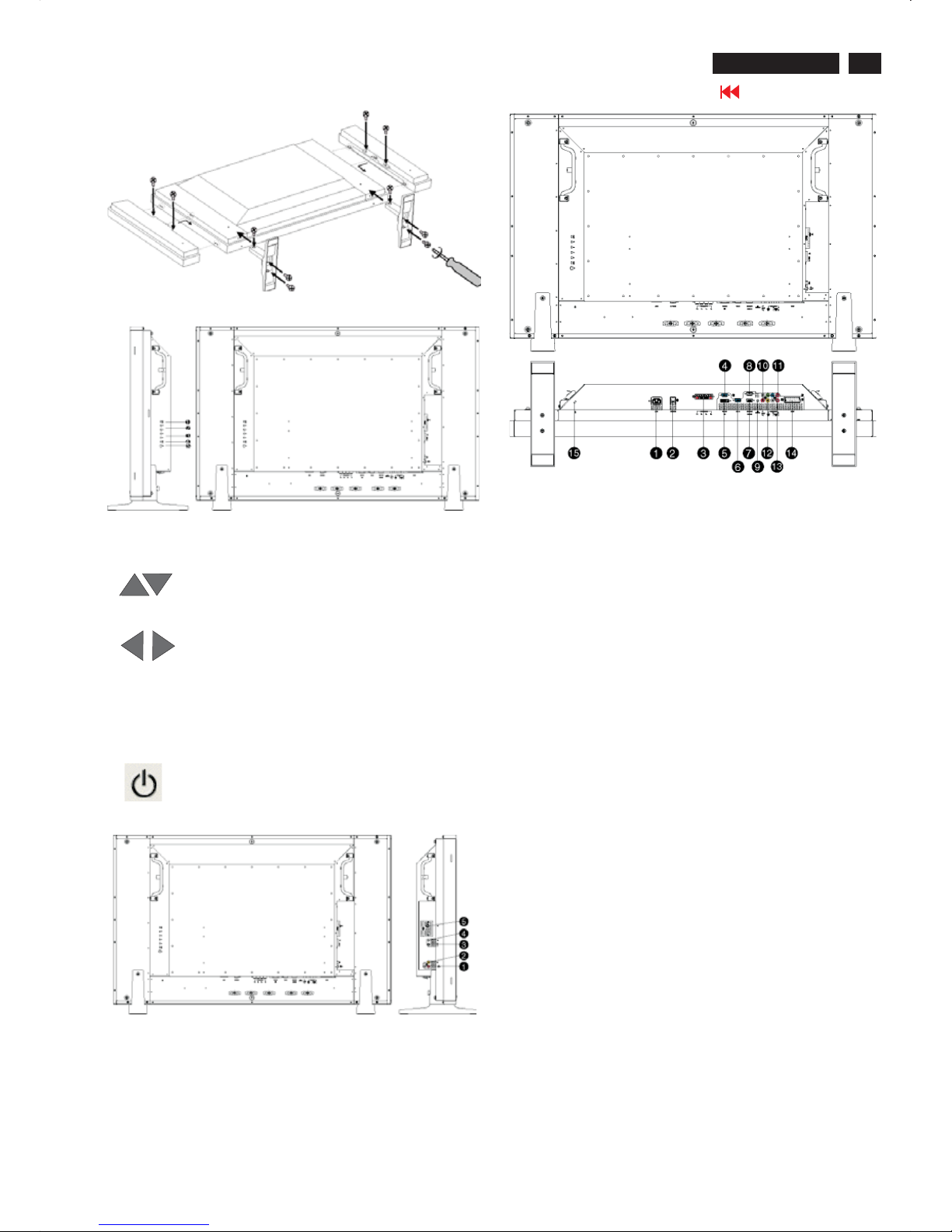
Side View(left)
1 INPUT Selecting input source
2. Increase or decrease the channelnumberor
moving up or down to highlight thefunction in OSD
3. Increase or decrease the levelof audio volume or
moving left or right to highlight the sub-menu in the
selected function of OSD
4. Openthe OSDorconfirm the selected function
5. DC powerswitch On/Off
Menu
Side View(Right)
1Audio input for composite input Audio (leftand right) in put for
compo site signal in put.
2 Composite input Composite(CVBS) signal input
3 S-Video input S-Video signal input
4 Earphone output Earphone output
5TVtunerTVtuner input (available in TV
version only)
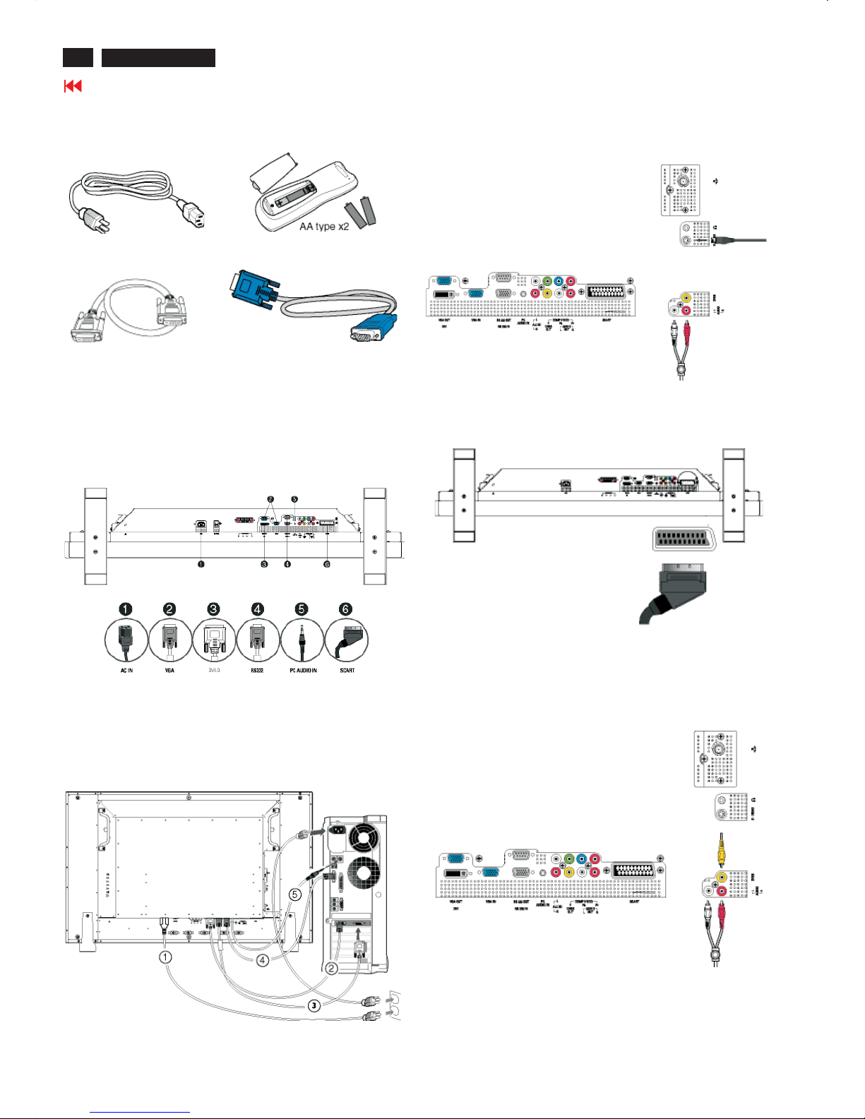
Rear View
1 ACin ACpowerin
2ACpowerACpowerswitch
3 Speakers output External speakers output
4D-Sub output PC analog D-Sub output
5 DVI-D input PC digital input
6D-Sub input PC analog D-Sub input
7 RS232 input RS232 network connection Input
8 RS232 output RS232 network conne ction output for the use of
loop through function
9PCaudio PC stereoaudio input
10 Audio input for component signal Audio (leftand right) input
for component signal input
11 Component input Component (YPbPr ) signal input
12 Composite output Composite(CVBS) output for the use
of loop through function
13 Audio output for composite output Audio (leftand right) out put
for compo site signal out put.
14 External / EURO-AV SCARTconnection (for the use of
European modelonly)
15 Kensington lock Kensington lock
6
420WN6 LCD TV
Go to cover page
Installation
Accessory Pack
Unpack all the parts
Power cable Remote control &batteries
DVI-D Cable VGA signal cable
Setting up and connecting your monitor/TV
CAUTION: Ensure that the power to the monitor/TV is switched off before
The installation.
- Connecting the monitor/TV
l Connect the cables to the rear of your monitor/TV according to the
numbers:
TV mo del
-Connect toPC
l Connect the cables to the back of your computer by following step 1~5.
l If your monitor displays the computer image the installation has been
completed successfully.
l If installation was not successful, see the Troubleshooting section.
l For installation of the monitor driver for Microsoft Windows® , see
the Monitor Driver Installation section
(Getting Started).
- Connect to DVD/VCD/VCR
Connect to DVD/VCR/VCD throu gh S-VIDEO
l Connect to DVD/VCR/VCD through S-VIDEO
Connect to DVD/VCR /VCD through SCART (for Europe only)
Connect to DVD/VCR /VCD through composite video (CVBS)
Connect to DVD/VCR /VCD through component video (YPbPr)

7
Installation
420WN6 LCD TV
Go to cover page
Connecting to Cable TV
Antenna
Progressive video and HDTV connections for digital high-definition picture
8
420WN6 LCD TV
Go to cover page
Philips' LCD Panel Pixel Defect Policy
Philips strives to deliver the highest quality products.We use some of the
industry's most advanced manufacturing processes and practise
stringent quality control. However, pixel or sub pixel defects on the TFT
LCD panels used in flat panel monitors are sometimes unavoidable.
No manufacturer can guarantee that all panels will be free from pixel
defects, but Philips guarantees that any monitor with an unacceptable
number of defects will be repaired or replaced under warranty. This
notice explains the different types of pixel defects and defines
acceptable defect levels for each type. In order to qualify for repair or
replacement under warranty, the number of pixel defects on a TFT
LCD panel must exceed these acceptable levels. For example, no more
than 0.0004% of the sub pixels on a 15" XGA monitor may be defective.
Furthermore,Philips sets even higher quality standards for certain types
Or combinations of pixel defects that are more noticeable than others.
This policy is valid worldwide.
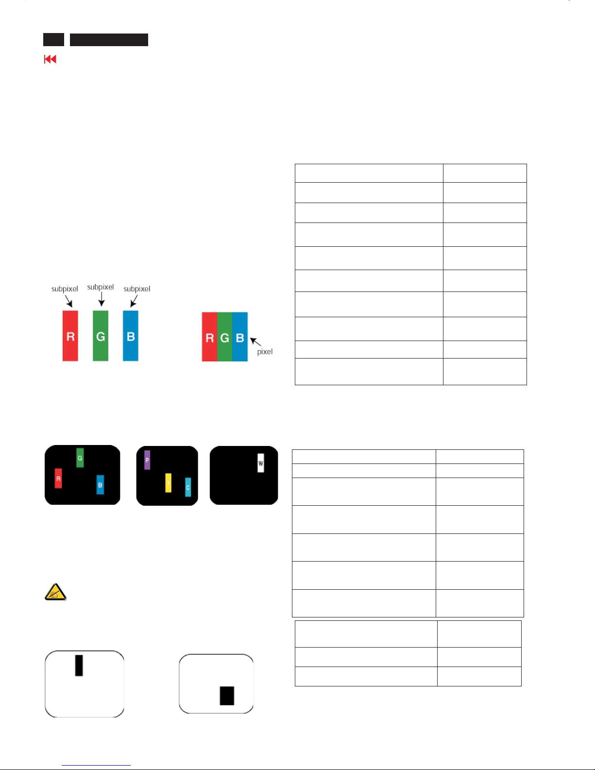
Pixels and Sub pixels
A pixel, or picture element, is composed of three sub pixels in the
primary colors of red, green and blue. Many pixels together form an
image. When all sub pixels of a pixel are lit, the three coloredsubpixels
together Appear as a single white pixel. When all are dark, the three
colored sub pixels together appear as a single black pixel. Other
combinations of lit and dark sub pixels appear as single pixels of other
colors.
Types of Pixel Defects
Pixel and sub pixel defects appear on the screen in different ways.
There are two categories of pixel defects and several types of sub pixel
defects within each category.
Bright Dot Defects Bright dot defects appear as pixels or sub pixels that
are always lit or 'on'. That is, a bright dot is a sub-pixel that stands out on
the screen when the monitor displays a dark pattern.
There are the types of bright dot defects:
One lit red, green or blue
sub pixel
Twoadjacentlitsubpixels:
- Red + Blue = Purple
- Red + Green = Yellow
- Green + Blue = Cyan (Light Blue)
Three adjacent lit sub
Pixels (one white pixel)
A red or blue bright dot must be more than 50 percent brighter
than neighboring dots while a green bright dot is 30 percent
brighter than neighboring dots.
Black Dot Defects Black dot defects appear as pixels or sub pixels that
are always dark or 'off'. That is, a dark dot is a sub-pixel that stands out
on the screen when the monitor displays a light pattern.
These are the types of black dot defects:
One dark sub pixel Two or three adjacent dark sub pixels
Proximity of Pixel Defects
Because pixel and sub pixels defects of the same type that are near to
one another may be more
noticeable, Philips also specifies tolerances for the proximity of pixel
defects.
Pixel Defect Tolerances
In order to qualify for repair or replacement due to pixel defects during
the warranty period, a TFT LCD panel in a Philips flat panel monitor
must have pixel or sub pixel defects exceeding the
tolerances listed in the following tables.
BRIGHT DOT DEFECTS ACCEPTABLE LEVEL
MODEL
420WN6
1litsubpixel 0
2 adjacent lit sub pixels 0
3 adjacent lit sub pixels (one white pixel) 0
75% ~ 50% of Dot 0
50% ~ Less Dot (Weak Dot) Max 7
Distance between two bright dot defects* N/A
Total bright dot defects of all types 0
Tiny bright dots less then 50% R/B, 30% G Ma
Max4
*Bright Dot is defined as dots (sub-pixels) which appeared brightly in the
screen when the LCM displayed with whole pattern & Bright Dot's
brightess is defined over 50% of the brightness against around. (but,
Green bright dot is over 30% of brightness against around)
*Here in Tiny Bright Dot is defined as "for Red and Blue" the bright area
should be no longer than1/2 sub-pixel and for green the bright area
should be no larger than 1/3 sub-pixel.
BLACK DOT DEFECTS ACCEPTABLE LEVEL
MODEL 420WN6
1 dark sub pixel 5 or fewer
2 adjacent dark sub pixels 1 or fewer
3 adjacent dark sub pixels 0
Distance between two black dot defects* 15 mm or more
Total black dot defects of all types 5 or fewer
TOTAL DOT DEFECTS
ACCEPTABLE L EVEL
MODEL
420WN6
Total bright or black dot defects of all types 5 or fewer
Note:
* 1 or 2 adjacent sub pixel defects = 1 dot defect
All Philips monitors are ISO13406-2 Compliant
Philips Pixel Defect Policy
9
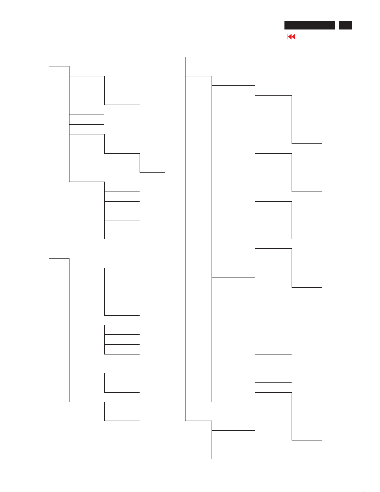
On Screen Display
420WN6 LCD TV
Go to cover page
PICTURE
SMART PICTURE FEATURES
p
NORMAL PIP
WARM SIZE
q
COOL
p
OFF
PC MAIN MENU
BRIGHTNESS SMALL
CONTRAST MEDIUM
AUTO ADJUST LARGE
YES
q
PBP
STORE VIDEO
p
YES
p
TV
q
NO AV
MANUAL ADJUST S-VIDEO
PHASE
q
EXT
CLOCK AUDIO
HORIZON
TAL
p
PC
VERTICA
L
q
PIP
DISPLAY
AUDIO
p
ICON1
SMART SOUND ICON2
p
MUSIC SOURCE ICON3
THEATRE
p
PC
q
ICON4
NEWS DVI
q
PERSONA
L TV
SETTINGS AV
TREBLE S-VIDEO
BASS HD
BALANCE
q
EXT
VIRTUAL
SURROUND ZOOM
p
ON ZOOM ID
q
OFF ZOOM TYPE
AVL
p
OFF
p
YES 4X4
q
NO INSTALL 3X3
LANGUAGE 2X2
p
ENGLISH
q
1X5
DEUTSCH
FRANÇAIS
1.pc signal control
On Screen Display
10
Magnavox LCD TV
Go to cover page
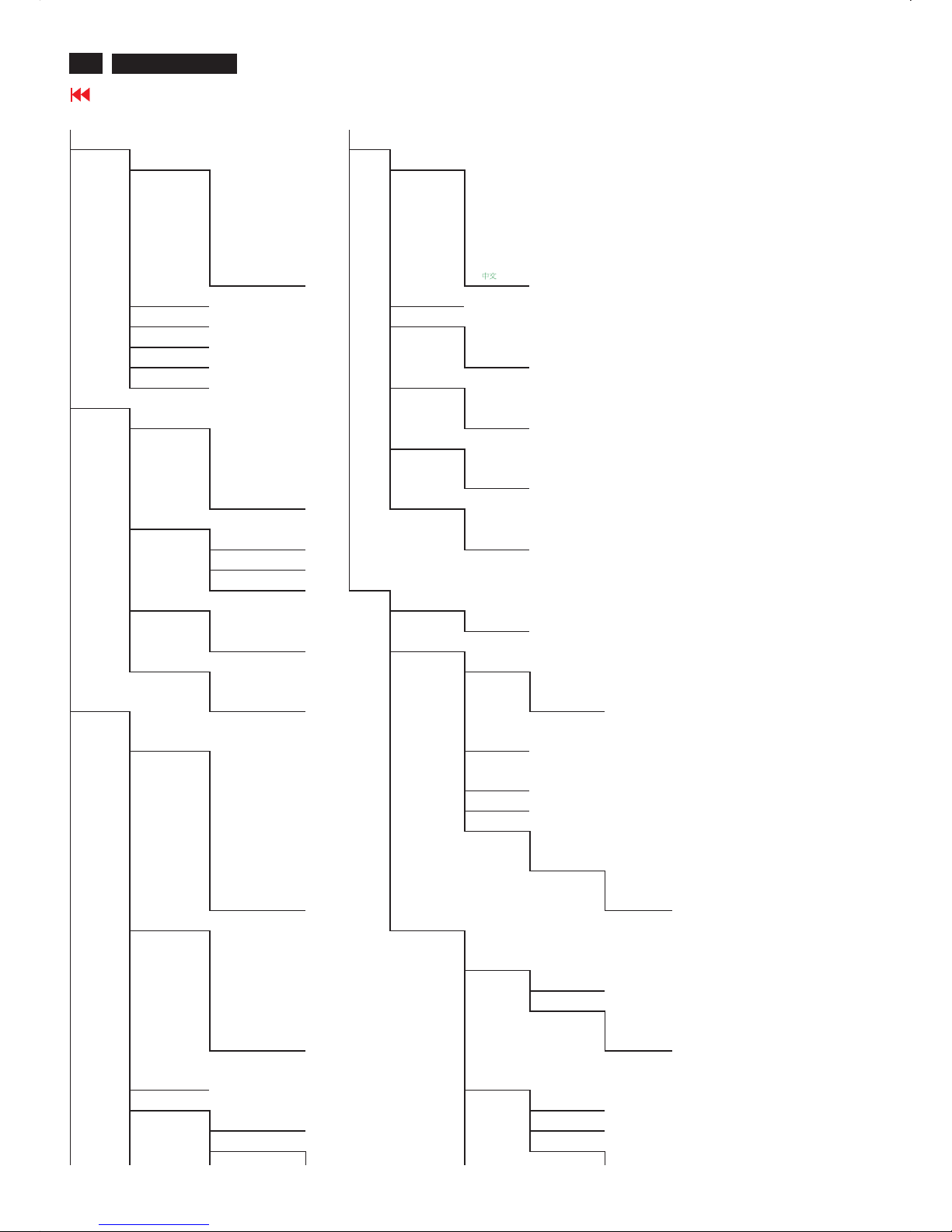
PICTURE INSTALL
SMART PICTURE LANGUAGE
p
SPORTS
p
ENGLISH
MOVIES DEUTSCH
WEAK SIGNAL FRANÇAIS
TV MAIN MENU
NIGHT ITALIANO
MULTIMEDIA ESPAÑOL
q
PERSONAL
q
BRIGHTNESS MONITOR ID
CONTRAST DCR
COLOR
p
ON
SHARPNESS
q
OFF
TINT LIGHT SENSOR
AUDIO
p
ON
SMART SOUND
q
OFF
p
MUSIC REMOTE CONTROL
THEATRE
p
ON
NEWS
q
OFF
q
PERSONAL FACTORY RESET
SETTINGS
p
NO
TREBLE
q
YES
BASS
BALANCE SETUP
VIRTUAL SURROUND AUTO PROGRAM
p
ON START
q
OFF MANUALSTORE
AVL SYSTEM
p
YES
p
FRANCE
FEATURES
q
NO
q
WEST EUROPE
SOURCE
p
PC
MANUAL
STORE
DVI
HDCP
PROGRAM
NUMBER
TV FINE TUNE
AV STORE
S-VIDEO YES
HD STORE
q
EXT
p
YES
q
NO
PICTURE FORMAT CHANNEL SETTING
p
AUTOMATIC
CHANNEL
EDIT
4:3 CHANNEL
ZOOM 16:9 SKIP
WIDESCREEN
p
ACTIVATE
q
SUPER WIDE
q
SKIP
PICTURE
ALIGNMENT
CHANNEL
SWAP
AUTO LOCK FROM
LOCK PROGRAM TO
CHANGE CODE EXCHANGE
YES EXCHANGED
2.TV signal control
WE/AP/China
11
On Screen Display
420WN6 LCD TV
Go to cover page
PICTURE SETUP
SMART PICTURE TUNER MODE
p
SPORTS
p
ANTENNA
BRIGHTNESS MOVIES CABLE
CONTRAST WEAK SIGNAL
q
AUTO
TV MAIN MENU
COLOR NIGHT AUTO PROGRAM
SHARPNESS MULTIMEDIA START
TINT
q
PERSONAL CHANNEL EDIT
AUDIO CHANNEL
SMART SOUND
p
MUSIC SKIP
THEATRE
p
ACTIVATE
NEWS
q
SKIP
q
PERSONAL MANUAL F INE TUNE
SETTINGS RATING
TREBLE BLOCK OPTION
BASS
p
ON
BALANCE
q
OFF
VIRTUAL SURROUND
p
ON MOVIE RATING
q
OFF G
p
ON
AVL
p
YES
q
OFF
q
NO PG
FEATURES
p
PC PG13
SOURCE
DVI
HDCP R
TV NC17
AV X
S-VIDEO
HD TV RATING
q
EXT TV Y
TV Y7
PICTURE FORMAT
p
AUTOMATIC BLOCK
4:3 FV
ZOOM 16:9 TV G
WIDESCREEN TV PG
q
SUPER WIDE BLOCK
PICTURE ALIGNMENT V
AUTO LOCK S
LOCK PROGRAM L
CHANGE CODE D
YES TV 14
CLEAR ALL BLOCK
p
ON V
ZOOM
q
OFF S
ZOOM ID L
ZOOM TYPE
p
OFF D
INSTALL 4X4 TVMA
LANGUAGE
p
ENGLISH 3X3 BLOCK
DEUTSCH 2X2 V
FRANÇAIS
q
1X5 S
ITALIANO L
ESPAÑOL CLOSED CAPTION
NAFTAMODE
12
420WN6 LCD TV
Go to cover page
AGING...
After 55 seconds, bring up:
After 5 seconds, bring up:
AGING...
After 55 seconds, bring up:
----------
---------repeatly
Connect Signal cable again=> go back to normal display
Access Aging.. Mode
Step 1 : Select the source "PC" and then turn off LCD-TV, and disconnect
Interface Cable between Monitor and PC.
Step 2 : [Push "power " button and then push the "Left " and "Right"
buttons at the same time immediately and hold it] untill comes out
" AGING screen" then release all buttons.
Bring up:
OSDLock
OSD function can be locked by
· Pressing Menu button for more than 10 seconds while there is
video signal in. The screen automatically shows OSD MAIN MENU
LOCKED for 3 seconds.
When users press Menu button, OSDLock MENU will appear,
and the default cursor location will be on unlock.
OSD can be unlocked by
· Pressing front panel Menu button for more than 10 seconds
while there is video signal in. As the menu button is pressed, the
screen will keep showing OSD MAIN MENU LOCKED until OSD
function unlocked. Then, OSD MAIN MENU UNLOCK will
automatically show for 3 seconds.
"
"
"
"
"
"
Aging Mode/OSD LOCK/UNLOCK
13
Factory Mode
420WN6 LCD TV
Go to cover page
Access factory. Mode
how to get into factory mode menu
Step 1 :Select the source "PC" andthen turn off LCD-TV.
Step 2 : [Push "power "button andthen push the "VOL-"and "VOL+"
buttons at the sametime immed
iatelyand hold it] about five seconds
then releaseall buttons.
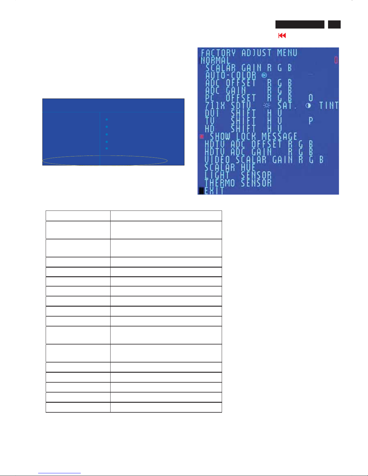
Press "menu"button and bringupfactory mode indication asshown in
Fig.1
Usethe "UP" and "DOWN" to select the "last line" andthenpre
ss
the "Right"button
MAINCONTROLS
SMART PICTURE
AUDIO BRIGHTNESS
FEATURES CONTRAST
INSTALL AUTOADJUST
MANUAL ADJUST
NEWMODE
PICTURE
BDS 32*420WN6 EU VO.42.60505OLC 32 *A6K3*A1
Fig.1
Menu Item Description
Scalar Gain R G B Scalar Gain for Normal/Warm/CoolinPC
mode.
Auto-Color Adjustcolor from received signal (either in
PCorHDTV mode).
ADC Offset RGB Adjust AD 9883 for PC ADC offset.
ADC Gain R G B Adjust AD 9883 for PC ADC gain.
PC Offset RGB PCanalogscalar offset.
711X SDTV Brightness Adjust SA 7119 SDTV brightness.
711X SDTV SAT.Adjust SA 7119 SDTV saturation.
711X SDTV Contrast Adjust SA 7119 SDTV contrast.
711X SDTV TINT Adjust SA 7119 SDTV tint(hue).
TV Shift H V AdjustTV screenposition
horizontally/vertically.
HD Shift H V Adjust HDTV screenposition
horizontally/vertically.
Show Lock Message ShowOSD lock message.
HDTV ADC Offset RGB Adjust AD 9883 for HDTV ADC offset.
HDTV ADC Gain R G B Adjust AD 9883 for HDTV ADC gain.
Video Scalar Gain R G B Adjust scalar gain for Video mode.
Scalar Hue Adjust scalar hue.

Warning Message
14
420WN6 LCD TV
Go to cover page
""
'
1.Automatic adjustment (for factory only)
Press Volume+ and Volume- on front key at the same time (PC mode only). It adjusts PC
image to the best and save the screen automatically.
2.OUTOFRANGE
If PC input timing is out of range, it shows OUT OF RANGE warning message on the center
of the screen. The range of horizontal frequency is between 14 - 63 KHz. The range of vertical
frequency is between 45 - 76 Hz. The OSD won t timeout.
3.NO VIDEO INPUT
When PC input timing has either horizontal frequency or vertical frequency. Or neither has
horizontal frequency nor vertical frequency. It shows on the center of the screen for 30
seconds, then it will enter sleep mode.
15
Trouble Shooting
420WN6 LCD TV
Go to cover page
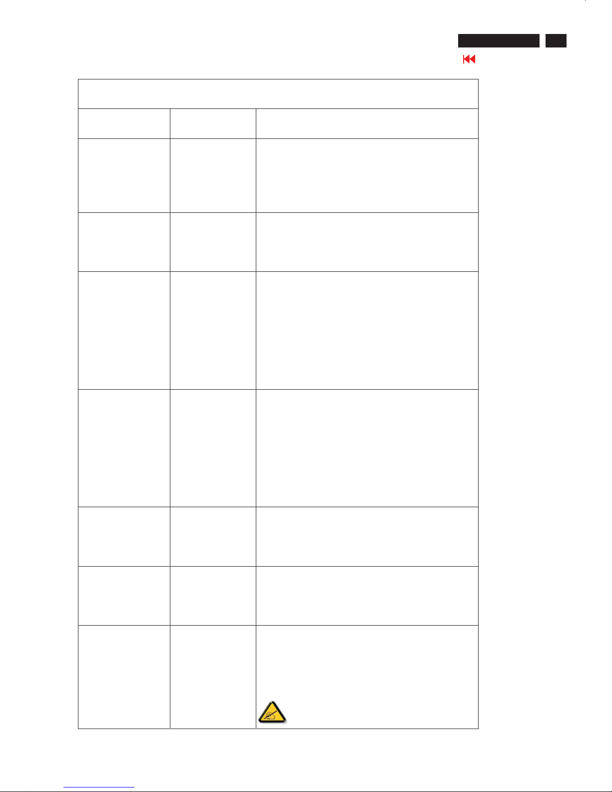
Common Problems
Symptoms Having this problem? Check these items
No Video/ Power
LED off
No picture, the LCD
Monitor TV is not
working
*Check connection integrity at both ends of the video cable
and/or power cord.
* Electric outlet verification
* Ensure AC power at the rear of the monitor TV is switched on.
No Video/ Power
LED on
No picture or no
brightness
*Increase brightness and contrast controls.
* Perform the LCD Monitor TV self-test feature check.
* Check for bent or broken pins in video cable connector.
Poor Focus Picture is fuzzy,
blurry or ghosting
*Auto adjust image through Menu -> Image Setting -> Auto
Adjust.
*Adjust Phase and Clock controls via OSD.
*Eliminate video extension cables.
*Perform the LCD Monitor TV factory reset (via Menu -> Factory
Reset -> All Settings).
*Lower video resolution or increase font size.
Shaky/Jittery Video Wavy picture or
fine movement
*Auto adjust image through Menu -> Image Setting -> Auto
Adjust
*Adjust Phase and Clock controls via OSD
*Perform the LCD Monitor TV factory reset (via Menu -> Factory
Reset -> All Settings)
*Check environmental factors
*Relocate and test in other room
Missing Pixels LCD screen has spots *Cycle power on-off
* These are pixels that are permanently off and is a natural
defect that occurs in LCD technology
Stuck-on Pixels LCD screen has
bright spots
*Cycle power on-off
* These are pixels that are permanently on and is a natural
defect that occurs in LCD technology
Brightness Problems Picture too dim or
too bright
*Perform the LCD Monitor TV factory reset (via Menu -> Factory
Reset -> All Settings)
*Auto adjust image through Menu -> Image Setting -> Auto
Adjust
*Adjust brightness & contrast controls
Note: When operating in DVI mode, the
contrast adjustment is not available.
16
420WN6 LCD TV
Go to cover page
Trouble Shooting
Geometric Distortion Screen not
centered correctly
*Perform the LCD Monitor TV reset on "Position Settings Only"
*Auto adjust image through Menu -> Image Setting -> Auto
Adjust
*Adjust the centering controls
*Ensure the LCD Monitor TV is in proper video mode
Note: When operating in DVI mode, the
positioning
adjustments are not available.
Horizontal/Vertical
Lines
Screen has one or
more lines
*Perform the LCD Monitor TV reset
*Auto adjust image through Menu -> Image Setting -> Auto
Adjust
*Adjust Phase and Clock controls via OSD
*Check for bent or broken pins in the video cable connector
Note: When operating in DVI mode, the Pixel
Clock and Phase
adjustments are not available.
Sync Problems Screen is
scrambled or
appears torn
*Perform the LCD Monitor TV reset
* Push Auto Adjust button
* Adjust Phase and Clock controls via OSD
* Check for bent or broken pins
* Boot up in the "safe mode"
LCD Scratched Screen has scratches
or
smudges
*Turn the LCD Monitor TV off and clean the screen
Safety Related
Issues
Visible signs of
smoke or sparks
*Do not perform any troubleshooting steps
*The LCD Monitor TV needs to be replaced
Intermittent Problems The LCD Monitor
TV malfunctions
on & off
*Ensure the LCD Monitor TV is in proper video mode
* Ensure video cable connection between computer and the
LCD monitor TV is secured
*Perform the LCD Monitor TV factory reset (via Menu ->
Factory Reset -> All Settings)
* Perform the LCD Monitor TV self-test feature check to
determine if the intermittent problem occurs in self-test mode
TV and Audio Problems
Poor TV signal
reception
Abnormal picture
seen from the
screen
*The proximity of mountains or high buildings may be
responsible for ghost pictures, echoing or shadows. In this
case, try manually adjusting your pictures: see 'fine tuning' or
adjust the direction of the outside aerial.
17
Trouble Shooting
420WN6 LCD TV
Go to cover page
No TV picture No picture when
TV input was
selected
*Have you connected the aerial socket properly? Have you
chosen the right system? Poorly connected SCART cables or
aerial sockets are often the cause of picture or sound problems
(sometimes the connectors can become half disconnected if the
LCD Monitor TV set is moved or turned). Check all
connections.
No sound No sound output
when a program
with sound was
playing
*Ensure that the audio cables are firmly connected to both the
audio input connectors on your the LCD Monitor TV and audio
output connectors on your PC or Video player.
*If on certain TV channels you receive a picture but no sound,
this means that you do not have the correct TV system. Modify
the SYSTEM setting.
Video Problems
No Video No signal indicator
is displayed.
*Check Video Input Selection
Composite: Yellow colored RCA jack
S-Video: Typically a round 4 pin jack
Component: Typically 3 RCA jacks of Green, Red and Blue.
*Make sure you did not plug the video cable to video output port
behind the LCD monitor TV.
Low Quality DVD
playback
Picture not crisp
and some color
distortion
*Check DVD connection
Composite gives good picture
S-Video gives better picture
Component gives best picture
No sound See video but no
audio
*Check if the LCD Monitor TV volume is turn off of muted.
*Connect the audio cable securely.
*Audio cable is connected incorrectly.
*Verify that the audio source is selected correctly in the OSD.
Remote Control Problems
Remote control does
not work properly
No response from
the LCD Monitor
TV when remote
is pressed
*Point the remote control directly at the remote sensor on the
LCD Monitor TV.
* Replace both batteries with new ones.
* Make sure the remote control is not disabled (for
disable/enable the remote control, please refer to the section of
Remote Control).
Produc t Spec ific Pr obl ems
Screen image is too
small
Image is centered
on screen, but
does not fill entire
viewing area
Perform the LCD Monitor TV factory reset (via
Menu -> Factory Reset -> All Settings).
Cannot adjust the
LCD Monitor TV with
the buttons at the
side of the unit
OSD does not
appear on the
screen
Turn the LCD Monitor TV off and unplug the
power cord and then plug back and power on.
18
420WN6 LCD TV
Go to cover page
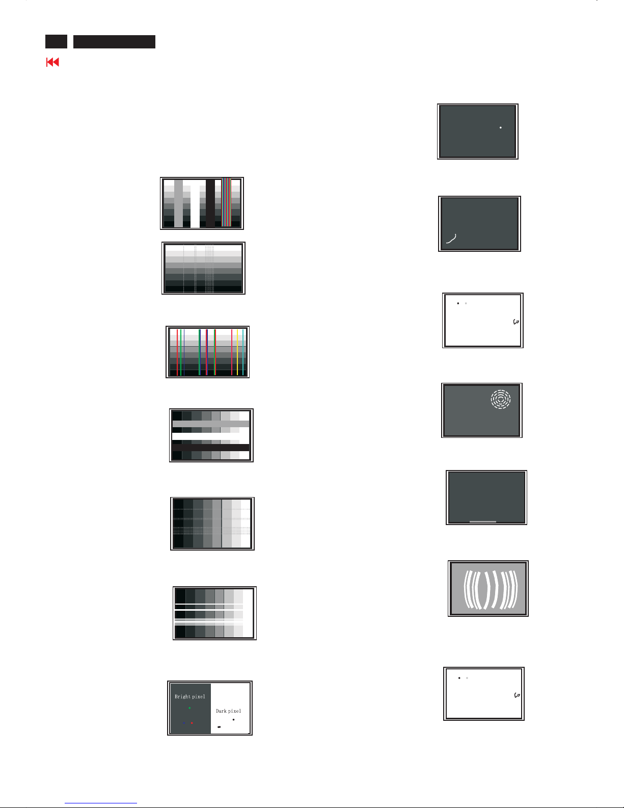
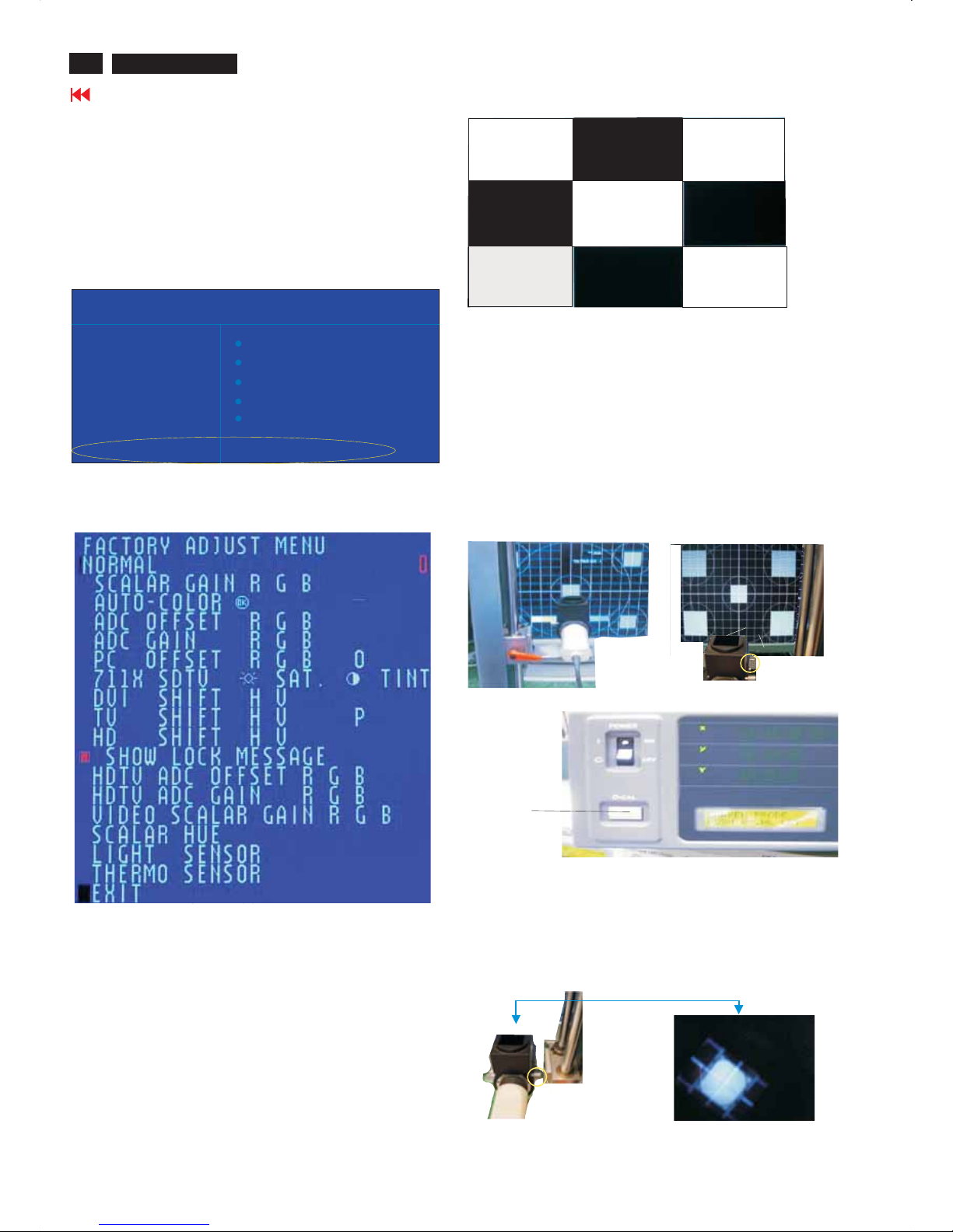
Failure description
Phenomenon
Vertical block defect
Vertical dim lines
Vertical lines defect
(Always bright or dark)
Horizontal block defect
Horizontal dim lines
Horizontal lines defect
(Always bright or dark)
Has bright or dark pixel
Polarizer has bubbles
Polarizer has bubbles
Foreign material inside
polarizer. It shows liner or
dot shape.
Concentric circle formed
Bottom back light of LCD is
brighter than normal
Back light un-uniformity
Backlight has foreign material.
Black or white color, liner or
circular type
Quick reference for failure mode of LCD panel
this page presents problems that could be made by LCD panel.
It is not necessary to repair circuit board. Simply follow the mechanical
instruction on this manual to eliminate failure by replace LCD panel.
Failure Mode Of Panel
19
420WN6 LCD TV
Go to cover page
All units that are returned for service or repair must pass the
original manufactures safety tests. Safety testing requires both
and testing.Hipot Ground Continuity
HI-POT TEST INSTRUCTION
1.Application requirements
2.
1.1 All mains operated products must pass the Hi-Pot test as
described in this instruction.
1.2This test must be performed again after the covers have
been refitted following the repair, inspection or modification
of the product.
2.1Connecting conditions
2.1.1The test specified must be applied between the parallel-
blade plug of the mainscord and all accessible metal
parts of the product.
2.1.2 Before carrying out the test, reliable conductive
connections must be ensured and thereafter be
maintained throughout the test period.
2.1.3 The mains switch(es) must be in the "ON" position.
2.2Test Requirements
All products should be HiPot and Ground Continuity tested as
follows:
Test 2820VDC 1700VDC Test current:
voltage (2000VAC)(1200VAC) 25A,AC
Test time:
Test time 3 seconds 1 second 3 seconds(min.)
(min.) Resistance
required:
Trip set at 100 uA 5 mA <=0.09+Rohm,
current for Max. R is the
(Tester) limitation; set resistance of
at 0.1 uA for the mains cord.
Min. Limitation
Ramp set at 2
time seconds
(Tester)
Test method
Condition HiPot Test for HiPot Test for Ground Continuity
products where products where Test requirement
the mains input the mains input is
range is Full 110V AC(USA
range(or 220V type)
AC)
2.2.1The minimum test duration for Quality Control Inspector
must be 1 minute.
2.2.2The test voltage must be maintained within the specified
voltage + 5%.
2.2.3 There must be no breakdown during the test.
2.2.4The grounding blade or pin of mains plug must be
conducted with accessible metal parts.
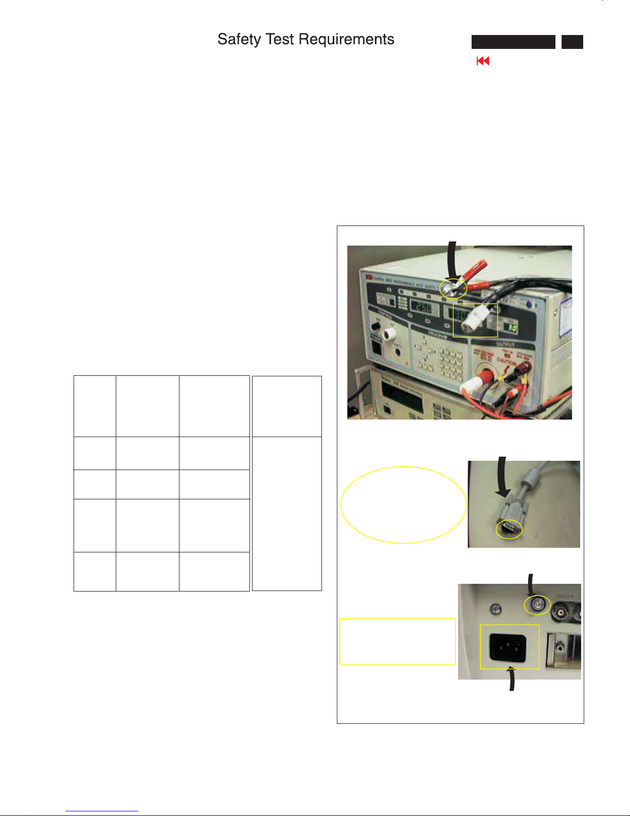
3. Equipments and Connection
3.1. Equipments
For example :
- ChenHwa 9032 PROGRAMMABLEAUTO SAFETY
TESTER
- ChenHwa 510B Digital Grounding Continuity Tester
- ChenHwa 901 (AC Hi-pot test), 902 (AC, DC Hi-pot test)
Withstanding Tester
3.2. Connection
4. Recording
Hipot and Ground Continuity testing records have to be kept
for a period of 10 years.
* Turn on the power switch of monitor before Hipot and
Ground Continuity testing.
Connect the "video cable"
or "grounding screw"
to the CLIP onyourtester.
Video cable
(Rear view of monitor)
Connect thepower cord
to the monitor.
Grounding screw
Power outlet
(ChenHwa 9032 tester)
Clip
Clip
20
420WN6 LCD TV
Go to cover page
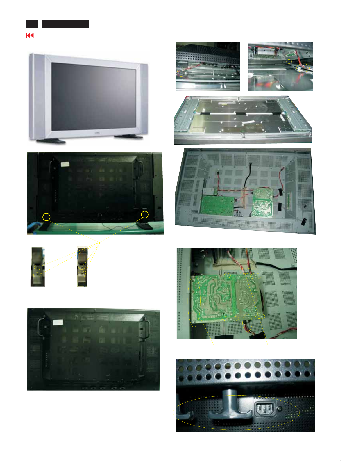
Mechanical Instructions
Front View
Back view
Remove the base, unscrew the screws
Remove all the screws on the four sides
After unscrew all the screws ,rise the back cover slowly and carefully
then you will see the following picture. you should disconnect all the
connector carefully and the remove the back cover.
Remove the scaler board and power board and TV BOX
Unscrew all the screws and disconnect the connectors on the power
board and unscrew the screws on the side as shown in following
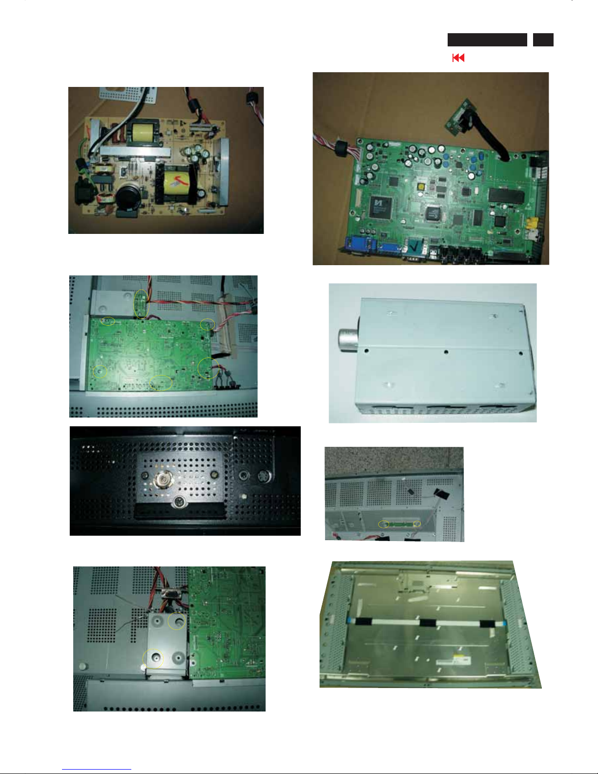
21
Mechanical instructions
420WN6 LCD TV
Go to cover page
Then removethepower board
Remove the scaler board:
-unscrew all the screwsonthescalerboard and on the side
-disconnect the connectors
-then remove the scaler board and the TV BOX
After you removetheTVBOX then unscrew the screws
Unscrew the screwsand open the click to remove the control board
22
420WN6 LCD TV
Go to cover page
Electrical Instructions
1. General points
1.1During the test and measuring, supply a distortion free AC
mains voltage to the apparatus via an isolated transformer
with low internal resistance.
1.2 All measurements mentioned hereafter are carried out at a
Normal mains voltage (90 - 142 VAC for NAFTA version,
195 -264 VAC for EUROPEAN version, or 90 - 264 VAC for
the model with full range power supply, unless otherwise stated.)
1.3 All voltages are to be measurement or applied with respect
to ground, unless otherwise stated.
1.4 The test has to be done on a complete set including LCD
panel in a room with temperature of 25 +/- 5 degree C.
1.5 All values mentioned in these test instruction are only applicable
of a well aligned apparatus, with correct signal.
1.6 The letters symbols (B) and (S) placed behind the test instruction
denotes
(B): carried out 100% inspection at assembly line
(S): carried out test by sampling
1.7 The white balance (color temperature), has to be tested in
subdued lighted room.
1.8 Repetitive power on/off cycle are allowed except it should be
avoided within 6 sec.
2. Input and output signal
2.1.1 PC Signal type
a.Analog Video : 15 pin D-sub ,0.7 Vp-p linear, positive
polarity & separate sync.( TTL level, positive or negative polarity)
b.Digital Video : DVI-Digital interface with 4 channels TMDS signal
c.Audio signal : 3.5mm stereo mini-jack
Level: Nominal : 0.5 V rms.
- Maximum : 1.5 V rms.
-Impedance > 10 k ohm.
d.Signal source: Pattern generator format as the SPEC.
Reference generator : CHROMA 2200 or 2250
2.1.2 TV Signal type(Video Model: w/o RF signal input )
RF Signal : Aerial input / 10mV(80dBuV)
Video signal : CVBS input ( RCA jack) / 1Vpp (300mV-sync,
700mV-video.)
S video input / 1VppY-signal, 300mVpp C-signal
SCARTx1: CVBS, RGB signal
HD in(YPbPr input)/ 1Vpp Y signal, 350mVpp Pb,Pr signal
HDCP:Digital interface with 4 channels TMDS signal
Audio signal : Audio (1) R/L for AV IN(AV and S-Video).
Level: - Nominal : 0.5 V rms.
- Maximum : 1.5 V rms.
- Impedance > 10 kohm.
Audio (2) R/L for SCART IN
Level: - Nominal : 0.5 V rms.
- Maximum : 1.5 V rms.
Impedance > 10 k ohm.
Audio (3) R/L for HD Video IN.
Level: - Nominal : 0.5 V rms.
-Maximum : 1.5 V rms.
- Impedance > 10 k ohm.
2.1.3 CVBS output:
Video: CVBS output 1Vpp / Impedance : 75ohm
Audio: R/L output (from CVBS)
Level: - Nominal : 0.5 V rms.
- Maximum : 1.5 V rms.
- Impedance < 1 kohm.
2.1.4 Headphone
Audio: R/L output -10mW at 32ohm.
3.5mm stereo jack with switch
Impedance is between 8 and 600 ohm.
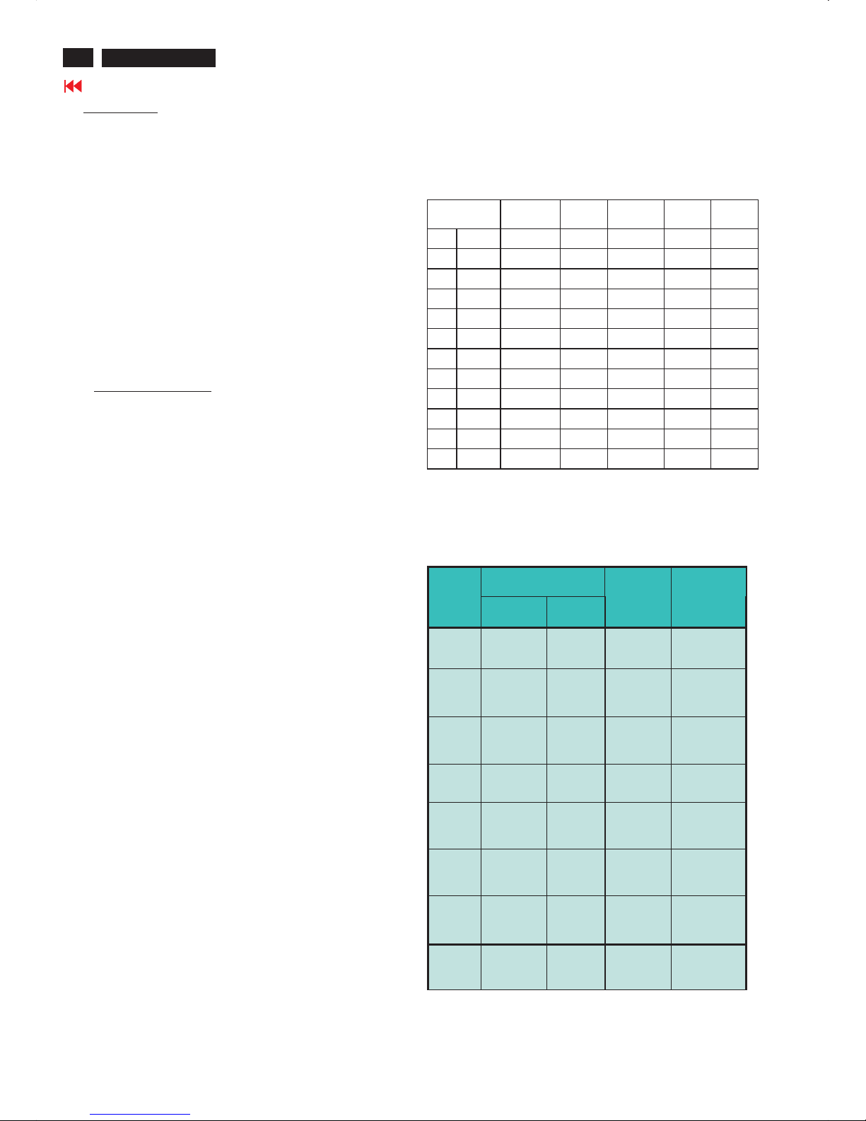
2.2 PC Input signal mode
2.2.1 PRESET VIDEO RESOLUTION
The analogue color LCD monitor must be capable of displaying
standard resolutions within the vertical frequency range of 50 - 75 Hz,
and horizontal scan range of 30 - 63 KHz .
Use the CHROMA-2250 generator as the standard signal timing source.
Dot rate
(MHz)
H.freq
(KHz)
Mode Resolution V.freq
(Hz)
Remark
1 25.175 31.469 VGA-1 640*350 70.086
2 25.175 31.469 IBM VGA 640 * 480 59.940
3 31.500 37.500 VGA 640 * 480 75.000
4 28.322 31.469 VGA 720*400 70.087
5 36.000 35.156 VESA 800 * 600 56.250
6 40.000 37.879 VESA 800 * 600 60.317
7 49.500 46.875 VESA 800 * 600 75.000
8 65.000 48.363 VESA 1024 * 768 60.004
9 78.750 60.023 VESA 1024 * 768 75.029
10 74.500 47.772 WXGA 1280 * 720 59.855 CVT
11 79.500 47.776 WXGA 1280 * 768 59.870 CVT
12 84.75 47.720 VSEA 1360 * 768 59.799 CVT
Resolution recommend on 1360x768 @ 60Hz
Remark:Mo de 1,3,4,5,7,9,11 will run aut o adjustmen t only ,
and W/O QA check ing
2.3 TV input signal Channel and pattern
2.3.1 Table 2.3.1 for NAFTA model
Signal Distribution Table (NTSC)
Frequenc y Carrier s
CH
Video So und
TV System
Pattern
A03 61.25MHz 65.75MHz NTSC M Color Circle
A06 83.25MHz 87.75MHz NTSC M Red Raster
A09 187.25MHz 191.75MHz NTSC M Circle Pattern
A11 199.25MHz 203.75MHz NTSC M Cross Hatch
A13 211.25MHz 215.75MHz NTSC M
Two White
Window
A52 699.25MHz 703.75MHz NTSC M Color Bar
A69 801.25MHz 805.75MHz NTSC M 100% White
C70 499.25MHz 503.75MHz NTSC M Checkerboard
Table 2.3.1
23
Electrical Instructions
420WN6 LCD TV
Go to cover page
2.3.2 Table 2.3.2 f or WE m odel
Signal Distribution Table ( PAL )
Frequenc y Carrier s
PRG CH
Video Sound
TV System
Pattern
0
1 AU37 590.25MHz 595.75MHz PAL B(UK) Pure White
2 AU2 64.25MHz 69.75MHz PAL B(UK) Circle Pattern
3 E7 189.25MHz 194.75MHz
PAL B
(CCIR)
Circle Pattern
4 G47 679.25MHz 684.75MHz
PAL G
(CCIR)
Circle Pattern
5 I23 487.25MHz 493.75MHz
PAL I
(UK)
Circle Pattern
6 E12 224.25MHz 229.75MHz
PAL B
(CCIR)
Color Bar
7 AU7 182.25MHz 187.75MHz
PAL B
(UK)
Color Bar
8 G68 847.25MHz 852.75MHz
PAL G
(CCIR)
100% White
9 AU9 196.25MHz 201.75MHz
PAL B
(UK)
Checkerboard
10
AU10 209.25 MHz 214.75 MHz
PAL B
(UK)
Crosshatch
11 AU0 46.25MHz 51.75MHz
PAL B
(UK)
Color Bar
12 AU2 64.25MHz 69.75MHz
PAL B
(UK)
Color Bar
13 AU5 102.25 MHz 107.75 MHz
PAL B
(UK)
Crosshatch
14 AU5A 138.25MHz 143.75MHz
PAL B
(UK)
Color Bar
15 AU7 182.25MHz 187.75MHz
PAL B
(UK)
Pure White
16 AU9 196.25MHz 201.75MHz
PAL B
(UK)
Pure White
17 AU10 209.25MHz 214.75MHz
PAL B
(UK)
Circle Pattern
18 I23 487.25MHz 493.75MHz
PAL I
(UK)
Circle Pattern
19 G28 527.25MHz 532.75MHz
PAL G
(CCIR)
Circle Pattern
20 AU37 590.25MHz 595.75MHz
PAL G
(UK)
Circle Pattern
21 I40 623.25MHz 629.75MHz
PAL I
(UK)
Color Bar
22 CH44 655.25MHz 661.75MHz
PAL DK
(UK)
Color Bar
23 I60 783.25MHz 789.75MHz
PAL I
(UK)
100% White
24 I66 831.25MHz 837.75MHz
PAL I
(UK)
Checkerboard
25 K21 471.25 MHz 477.75 MHz
SEC K1
(CCIR)
Crosshatch
28 G28 527.25MHz 532.75MHz
PAL G
(UK)
Color Bar
Table 2.3.2
2.3.3 Table 2.3.3 for AP-Multi model
Signal Distribution Table (PAL and NTSC)
Frequenc y Carrier s
PRG CH
Video Sound
TV System
Pattern
0
1 AU37 590.25MHz 595.75MHz PAL B(UK) Pure White
2 AU2 64.25MHz 69.75MHz PAL B(UK) Circle Pattern
3 E7 189.25MHz 194.75MHz
PAL B
(CCIR)
Circle Pattern
4 G47 679.25MHz 684.75MHz
PAL G
(CCIR)
Circle Pattern
5 I23 487.25MHz 493.75MHz
PAL I
(UK)
Circle Pattern
6 M58 735.25MHz 739.75MHz
NTSC M
(CCIR)
Color Bar
7 AU7 182.25MHz 187.75MHz
PAL B
(UK)
Color Bar
8 K21 471.25MHz 477.75MHz
PAL G
(CCIR)
100% White
9 AU9 196.25MHz 201.75MHz
PAL B
(UK)
Checkerboard
10 AU10 209.25 MHz 214.75 MHz
PAL B
(UK)
Crosshatch
11 E12 224.25MHz 229.75MHz
PAL B
(CCIR)
Color Bar
12 G34 575.25MHz 580.75MHz
PAL G
(CCIR)
Color Bar
13 G62 799.25 MHz 804.75 MHz
PAL G
(CCIR)
Crosshatch
14 C4 77.25MHz 83.75MHz
PAL D
(CCIR)
Color Bar
28 G28 527.25MHz 532.75MHz
PAL G
(UK)
Color Bar
2.3.4 TV Table 2.3.4 for Chi na model
Signal Distribution Table (PAL D) table 2.3.4
Frequenc y Carrier s
PRG CH
Video Sound
TV System
Pattern
1 C4 65.25MHz 71.75MHz PAL D
(CCIR)
Full Write
2 E7 184.25MHz 190.75MHz PAL D
(CCIR)
Circle
Pattern
3 E12 224.25MHz 230.75MHz
PAL D
(CCIR)
Color Bar
4 K21 471.25MHz 477.75MHz PAL D
(CCIR)
Full Write
5 G34 511.25MHz 517.75MHz PAL D
(CCIR)
Circle
Pattern
6 G62 547.25MHz 553.75MHz
PAL D
(CCIR)
Color Bar
7 M58 551.25MHz 557.75MHz PAL D
(CCIR)
Crosshatch
8 G47 615.25MHz 621.75MHz
PAL D
(CCIR)
Color Bar
24
420WN6 LCD TV
Go to cover page
Electrical Instructions
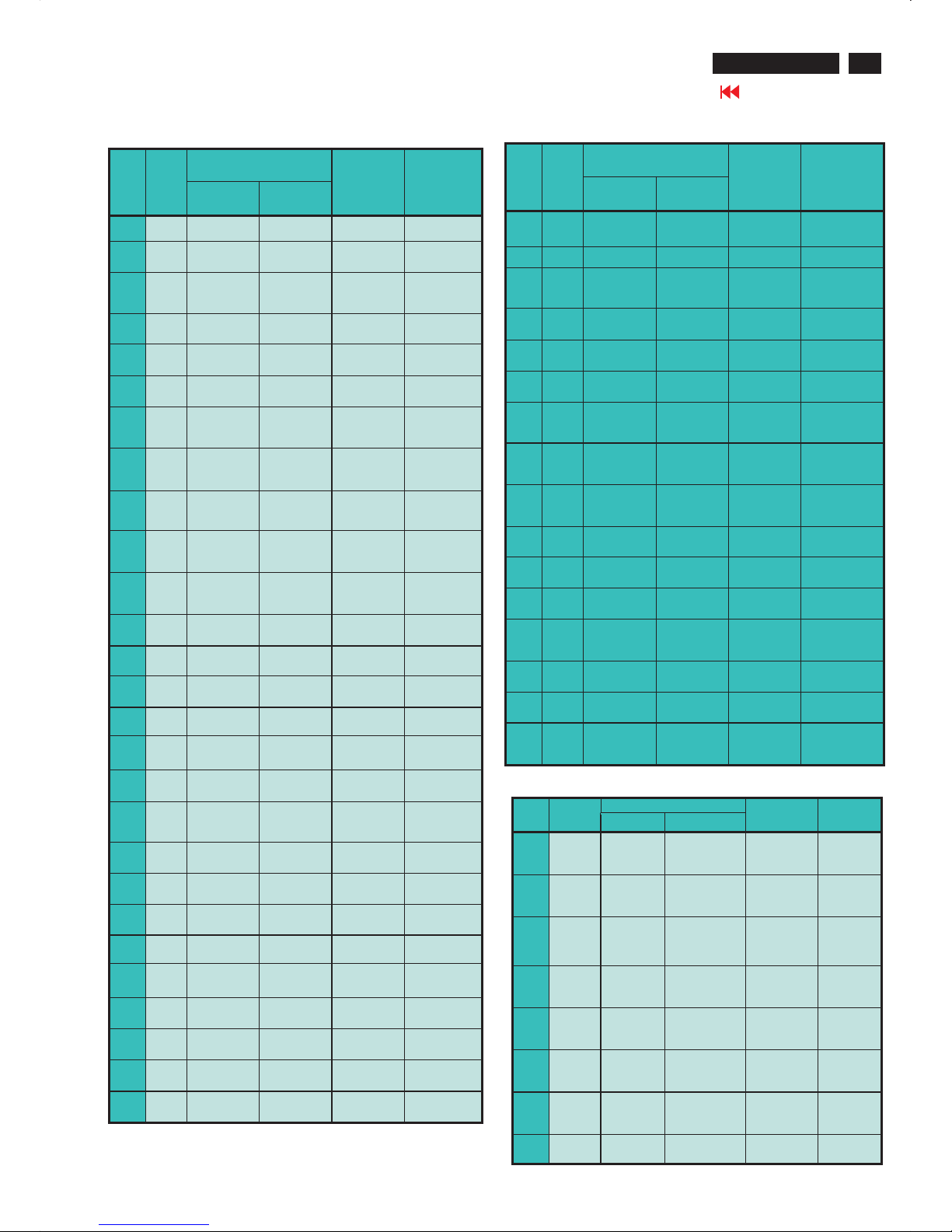
2.4 HD input mode
2.4.1 HD detail timing
(For Quantune Data setting with Q801GD or 802G in YpbPr mode)
Item 1920X108
0i 60Hz
1280X720P
60Hz
1920X1080i
50Hz
1280X720
P
50Hz
Pixel
rate
74.25MHz
(13.468
ns)
74.25MHz
(13.468 ns)
74.25MHz
( 13.468ns )
74.25MHz
(13.468
ns)
Horizont
al
Frequen
cy
33.75KHz 45KHz 28.125KHz 37.5KHz
Active 1920
pixels
(25.859
us)
1280 pixels
(17.239 us)
1920 pixels
(25.859 us)
1280
pixels
(17.239
us)
Blank 280 pixels
(3.771 us)
370 pixels
(4.983 us)
720 pixels
( 9.697 us )
700 pixels
(9.428 us)
Period 2200
pixels
(29.630
us)
1650 pixels
(22.222 us)
2640 pixels
( 35.556
us )
1980
pixels
(26.667
us)
Pulse
delay
44 pixels
(0.593 us)
70 pixels
(0.943 us)
484 pixels
( 6.519 us )
400 pixels
(5.387 us)
Pulse
width
44 pixels
(0.593 us)
40 pixels
(0.539 us)
44 pixels
( 0.593 us )
40 pixels
(0.539 us)
Vertical
Frequen
cy
60 Hz 60 Hz 50 Hz 50 Hz
Active 1080 lines
(42.000
ms)
720 lines
(16.0 ms)
1080 lines
( 38.4 ms )
720 lines
(19.2 ms)
Blank 45 lines
(1.333
ms)
30 lines
(0.667 ms)
45 lines
(1.6 ms )
30 lines
(0.8 ms)
Period 1125 lines
(33.333
ms)
750 lines
(16.667 ms)
1125 lines
(40ms)
750 lines
(20 ms)
Pulse
delay
2 lines
(0.059
ms)
5 lines
(0.111 ms )
2 lines
( 0.071 ms )
5 lines
(0.133
ms )
Pulse
width
5 lines
(0.148
ms)
5 lines
(0.111 ms)
5 lines
(0.178 ms )
5 lines
(0.133
ms)
EQ
before
0 line 0 line 0 line 0 line
EQ after 1 line 0 line 1 line 0 line
Scan Interlace Progressive Interlace Progressiv
e
Sync
type
ACS ACS ACS ACS
Video
kind
Analog
YPbPr
(ITU-R
BT.709)
Analog
YPbPr (ITUR BT.709)
Analog
YPbPr (ITURBT.709)
Analog
YPbPr
(ITU-R
BT.709)
Item 720X576P
50Hz
720X480P
60Hz
720X576i
50Hz
720X480i
60Hz
Pixel rate 27 MHz
(37.037
ns)
27.027MHz
(37.000 ns)
13.5MHz
( 74.074
ns )
13.5MHz
( 74.074
ns )
Horizontal
Frequency
31.25 KHz 31.5KHz 15.625KHz 15.734KHz
Active 720 pixels
(26.667
us)
720 pixels
(26.640
us)
720 pixels
(53.333 us)
720 pixels
(53.333
us)
Blank 144 pixels
(5.333 us)
138 pixels
(5.106 us)
144 pixels
( 10.667
us )
138 pixels
( 10.222
us )
Period 864 pixels
(42.000
us)
858 pixels
(31.746
us)
864 pixels
( 64.00 us )
858 pixels
( 63.556
us )
Pulse
delay
12 pixels
(0.444 us)
16 pixels
(0.592 us)
12 pixels
( 0.889 us )
19 pixels
( 1.407 us )
Pulse
width
64 pixels
(2.370 us)
62 pixels
(2.294 us)
63 pixels
( 4.667 us )
62 pixels
( 4.593 us )
Vertical
Frequen
cy
50 Hz 60 Hz 50 Hz 59.94 Hz
Active 576 lines
(18.442
ms)
480 lines
(15.238
ms)
576 lines
( 36.864
ms )
480 lines
( 30.507
ms )
Blank 49 lines
(1.568
ms )
45 lines
(1.429
ms)
49 lines
(3.136 ms )
45 lines
(2.860 ms )
Period 625 lines
(20.000
ms)
525 lines
(16.667
ms)
625 lines
(40ms)
525 lines
( 33.367
ms )
Pulse
delay
5 lines
(0.160
ms)
9 lines
(0.287
ms)
2 lines
( 0.128 ms )
4 lines
( 0.254 ms )
Pulse
width
5 lines
(0.160
ms)
6 lines
(0.190
ms)
3 lines
(0.192 ms )
3 lines
(0.191 ms )
EQ
before
0 line 0 line 2 line 3 line
EQ after 0 line 0 line 2 line 3 line
Scan ProgressiveProgressiveInterlace Interlace
Sync
type
ACS ACS ACS ACS
Video
kind
Analog
YPbPr
(SMPTE
RP177)
Analog
YPbPr
(SMPTE
RP177)
Analog
YPbPr
(SMPTE
RP177 )
Analog
YPbPr
(SMPTE
RP177 )
Table 2
3. Power supply
3.1 Setup the AC I/P at 264 VAC and 90VAC , and power board
provide two DC Output
1. The DC output voltage is 24V +/-1V DC for Inverter and Scaler
board Measured point between pin3(+24V) and pin6(GND) at
item 1001 of scaler board
2. The DC output voltage is 16V +/-1 V DC for Scaler and Audio board
Measured point between pin1(+16V) and pin6(GND) at item
1001 of scaler board
3.2 Any adjustment is not needed.
4. PC mode Display Adjustment
4.1 Displ ay quality ad jus tment
Use timing mode as describe in 2.2, and use the POPO (pixel
on pixel off) pattern to adjust the clock until no stripe and adjust
the phase until clear picture.
Adjust all pre-load 12 modes, but ignore the wave interference
on non-60 Hz modes.
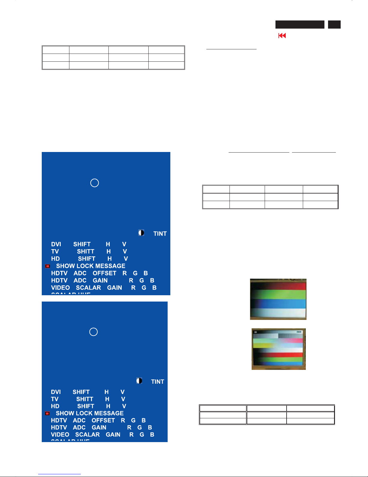
4.2 WHITE-D adjust ment (B)
4.2.1 At factory mode apply 1360X768 @60Hz mode with 32 gray
pattern. Set smart picture at Normal , and Brightness to 50% and
Contrast to 50%.
Set AUTO-COLOR function for auto ADC offset and gain setup.
4.2.2 Apply full white pattern , adjust the Cool,
Normal & Warm SCALER GAIN RG B
to reach W/D and luminance in factory mode.(See fig.1)
1. Check (X, Y) co-ordinates as below :
""
25
Electrical Instructions
420WN6 LCD TV
Go to cover page
Cool/9300°K Normal/6500°K Warm/5700°K
x (center) 0.283 ± 0.005 0.313 ± 0.005 0.328 ± 0.005
y (center) 0.297 ± 0.005 0.329 ± 0.005 0.344 ± 0.005
Table 4.2.2.1: Reading with Minolta CA-110.
2. Check the gray level color poor & noise condition and chromaticity
Note:
1. Use Minolta CA-110 for color coordinates and luminance check.
2.Set Light Senor off before W-D adjustment.
3. Lumin ance> 400 cd/m
2
in the center of the screen at
6500(NORAML)color and PC Brightness control; Contrast control
at 100%
4.Set smart picture at normal ,brightness &contrast to 50% after alignment.
5.Set Light senor off after Light senor check.
4.3 Check th e digital interface cable (B )
Check the 32 gray level color poor & noise condition.
FACTORY ADJUST MENU
NORMAL
30?C
SCALARGAINRGB
AUTO-COLOR
ADC OFFSET R G B
ADC GAIN R G B
PC OFFSETRGB
711X SDTV ? SAT.
OK
FACTORY ADJUST MENU
COOL
30?C
SCALARGAINRGB
AUTO-COLOR
ADC OFFSET R G B
ADC GAIN R G B
PC OFFSETRGB
711X SDTV ? SAT.
OK
Fig.1
Fig.2
5. TV Mode display adjust
5.1 White balance adjustment (B)
5.1.1 General set-up :
Equipment Requirements: Color analyzer.
Input requirements:
Input Signal Type : RF signal
1. Set to NTSC system, frequency=187.25MHZ ( for NAFTA
model ), with white pattern of 100%
2. Set to PAL B/G system, frequency=64.25MHz ( for WE
model ) with white pattern of 100%
Input Signal Strength : 10mV (80 dBuV) terminal voltage.
Input Injection Point : TV Tuner input
Alignment method:
Initial Set-up :
1.Set 711X SDTV Brightness=135; Sat. =64, Contrast =50
in Factory mode(can be fine tuned).
2. Set Smart picture as Personal
3. Apply 100% Full White pattern by TV pattern generator.
Alignment :
Set the VIDEO SCALER GAIN R G B
=SCALERGAINRGB
in Factory Mode(See Fig 2.)
[ Enter factory menu : press VOL+ and VOL- keys together around
six seconds or use factory command by Industrial PC.
1. Check (X, Y) co-ordinates in factory mode as below:
Table 5.1.1 Reading with Minolta CA-110.
2.Set TV Color temperature in Factory model as Cool, and
check smart picture at Sports after factory alignment.
3.Check the gray pattern should be distinguished and color bar
is correct.
4.SetTVDCRatON.
Cool/9300°K Nor mal/6500°K Warm /5700°K
x (center) 0.283 ± 0.015 0.313 ± 0.015 0.328 ± 0.015
y (center) 0.297 ± 0.015 0.329 ± 0.015 0.344 ± 0.015
""
""
6. HDTV Mode display adjust
6.1 White balance adjustment (B)
General set-up:
Equipment : Quantum Data Pattern Generator 801GD or 802G.
Apply 1080i, RGBW(Infocus2) gray pattern.
Or FLUKE 54200, apply 576i(PAL B/G), DIGITAL
SCAN/DIGI_ADC1 pattern.
Alignment method:
Initial Set-up
: 1.Set Smart picture as Personal , Brightness=50, Color=50,
Contrast=50)
2.Set AUTO-COLOR function for HDTV ADC offset & gain setup.
Alignments : 1. Apply 100% Full White pattern by Quantum
DATA 802G pattern generator.
Check (X, Y) co-ordinates as below:
If chromaticity (X, Y) co-ordinates is out of specification, re-alignment
Video scalar R/G/B gain from 127/127/127.
2. Set smart picture at sports after HDTV alignment.
3. Check the gray pattern should be distinguished and color bar is correct.
Picture Mode x y
Personal
0.283 ± 0.015 0.298 ± 0.015
""
""
Display Adjustment
26
420WN6 LCD TV
Go to cover page
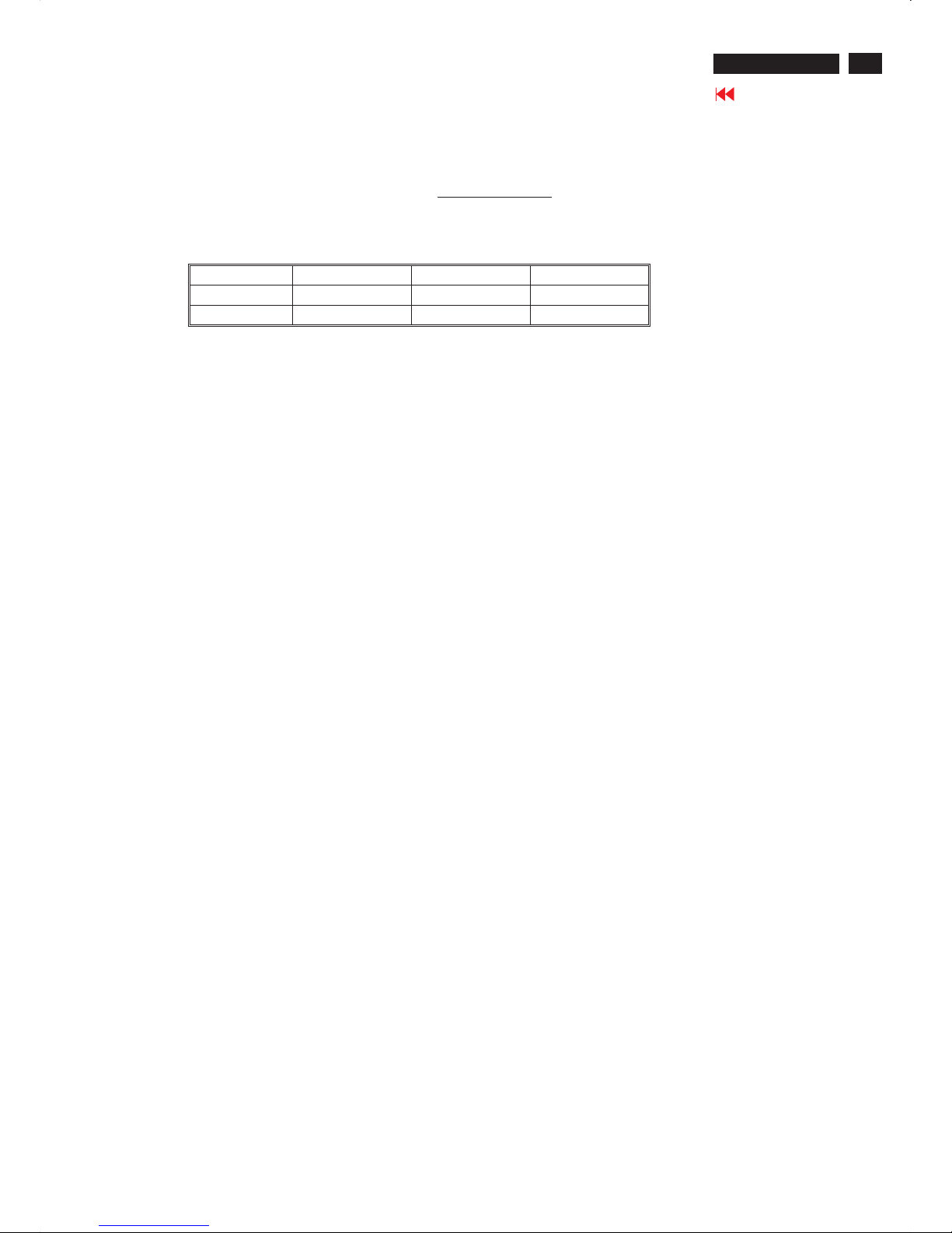
Fig. 1
Fig.7
Clear image
Measurement/viewing selector
Display adjustment
Access factory.Mode
how toget intofactorymode menu
Step 1:Selectthesource "PC" and then turn off LCD-TV.
Step 2 :[Push"power"button and then push the "VOL-"and "VOL+"
buttons at the same time immediately and hold it] about fiveseconds
then release all b
uttons.
Press "menu"button and bring up factorymode indicationasshownin
Fig.1
Use theDOWN and UP to selectthe "
" and then press the "VOL +" button
BDS32*420WN6 EU VO.42.6
0505OLC32*A6K3*A1
PCmode WHITE-D adjustment (B)
1 Apply 1024X768/60Hz mode with5block patternasFig3.Set
main controls brightness controlat50% and contrast to50% on
User mode.Set color setting at natural color on User mode.Move
cursor to"AUTO-color" item on fact
orymode, press "menu" key
to activethis function, then scalerwill adjust RGB and Color
RGB automatically byitself.
Fig.2
Fig.3
2. Apply a 1024x768/60Hz signal withwhite pattern.Set
brightness controlat50% and contrast controlat50%. Adjust the
R.G.B gain toreach special color temperature on centerof
screen.
2.1 Aim theprobeCA-A30atthe centerofscreen as Fig. 4
2.2 Removethe lens p
rotective coverofprobeCA-A30.
2.3 Set Measuring/viewing selector toMeasuring position for reset
analyzer. (Zero calibration) as Fig. 5
2.4Turn onthe colour analyzer (CA-110).
2.5 Press 0-CAL buttonto start reset analyzer. See Fig. 6
Cover (black)
Measurement viewing selector
O-CAL
Fig.4
Fig.6
Fig.5
2.6 Switch lightprobeto Viewing position.
2.7 Movethe Lens barrel forward or backwardtoget clear imageas
showninFig. 7
2.8 Switch lightprobetoMeasuring position. It should beable to
indicate colourvalue ontheCA-11
0.
MAIN CONTROLS
SMART PICTURE
AUDIOBRIGHTNESS
FEATURES CONTRAST
INSTALL AUTO ADJUST
MANUAL ADJUST
NEW MODE
PICTURE
BDS32*420WN6 EU VO.42.60505OLC32*A6K3*A1
Display adjustment
27
420WN6 LCD TV
Go to cover page
2.9 WHITE-D adjustment (B)
2.9.1 At factory mode apply 1360X768@60Hz mode with 32 gray pattern.
Set smart picture at Normal , and Brightness to 50%andContrast to 50%.
Set AUTO-COLOR function for auto ADC offset and gain setup.
2.9.2 Apply full white pattern , adjust the Cool, Normal & Warm SCALER GAIN RG B
to reach W/D and luminance in factory mode.(See fig.1)
1. Check (X, Y) co-ordinates as below :
Reading with Minolta CA-110.
2. Check the gray level color poor & noise condition and chromaticity
Note:
1. Use Minolta CA-110 for color coordinates and luminance check.
2.Set Light Senor off before W-D adjustment.
3. Luminance> 400 cd/m
2
in the center of the screen at 6500(NORAML)color
and PC Brightness control; Contrast control at 100%
4.Set smart picture at normal ,brightness &contrast to 50% after alignment.
5.Set Light senor off after Light senor check.
Cool/9300°K Normal/6500°K Warm /5700°K
x (center) 0.283 ± 0.005 0.313 ± 0.005 0.328 ± 0.005
y (center) 0.297 ± 0.005 0.329 ± 0.005 0.344 ± 0.005
""
28
420WN6 LCD TV
Go to cover page
Fig. 3Fig. 3
General
Pin assignment
A. 15-pin D-Sub Connector
DDC Data Re-programming
Analog DDC IC, & EEPROM
Additional information
In case the DDC data memory IC or main EEPROM which storage all
factory settings were replaced due to a defect, the serial numbers have
to be re-programmed" ".
It is advised to re-soldered DDC IC and main EEPROM from the old
board onto the new board if circuit board have been replaced, in this
case the DDC data does not need to be re-programmed.
Additional information about DDC (Display Data Channel) may be
obtained from Video Electronics Standards Association (VESA). Extended
Display Identification Data(EDID) information may be also obtained from
VESA.
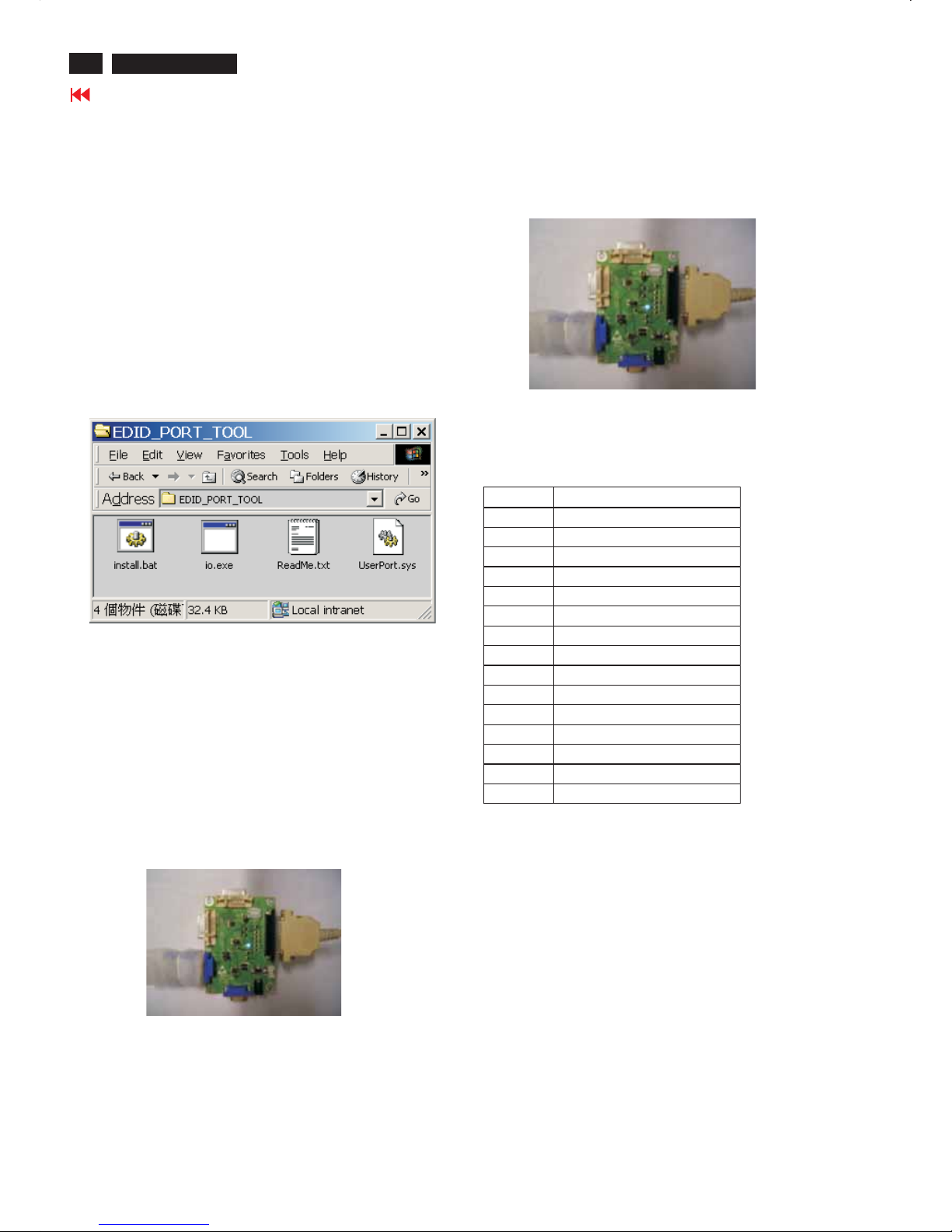
1. An i486 (or above) personal computer or compatible.
2. Microsoft operation system Windows 95/98 .
Y o Install the EDID_PORT_Tool under Win2000/XP . As
Fig. 1 .
A. Cody the "UserPort.sys" to C:\WINNT\system32\drivers(win2000)
C:\WINDOWS\system32\drivers(winXP)
B. Running " io.exe" everytime, Before you start to programming
edid data .
4.A/D Alignment kits (3138 106 10396):
inclusion : a. Alignment box x1 (as Fig.
2)
b. Printer cable x1
c. (D-Sub) to (D-Sub) cable x1
System and equipment requirements
ou have t
3. EDID45.EXE program .
Note: The alignment box has already build-in a batteries socket for
using as power source. Pull out the socket by
remove four screws at the rear of box. Please do not forget that
remove batteries after programming. The energy of batteries can
only drive circuits for a short period of time.
batteries (8~12V)
Fig. 2Fig. 2
Fig. 1Fig. 1
To Printer port
To Monitor
D-sub cable
ToPC
DDC INSTRUCTIONS
PINNo. SIGNAL b(PC)
1Red
2Green
3Blue
4GND
5 GND
6 Red GND
7Green GND
8 Blue GND
9 +5V (Supply from PC)
10 Sync GND
11 GND
12 Bi-directional data
13 H-sync
14V-sync
15 Data clock
29
DDC INSTRUCTIONS
420WN6 LCD TV
Go to cover page
Method 1: Start on DDC program
Fig. 5
Fig. 4
PC
1=Power connector
2= D-SUB connector
To printer port (
L
TP1)
Printer
Port
To
Monitor
ToPC
1
2
----->
----->
Fig. 8
Note 1: If the connection is improper, you will see the following error
message (as shown in Fig. 8) before entering the main menu.
Meanwhile, the (read EDID) function will be disable. At this
time,
please make sure all cables are connected correctly and
1
Fig. 9
4. Click button. The main menu appears (as shown in Fig. 7).OK
This is for initialize alignment box.
Fig. 7
Fig. 6
3. At the submenu, type the letter of your computer's hard disk drive
followed by :EDID45 (for example, C:\EDID45, as shown in Fig. 6).
5
TO VIDEOCARD
1
2
30
420WN6 LCD TV
Go to cover page
DDC INSTRUCTIONS
Re-programming DDC IC
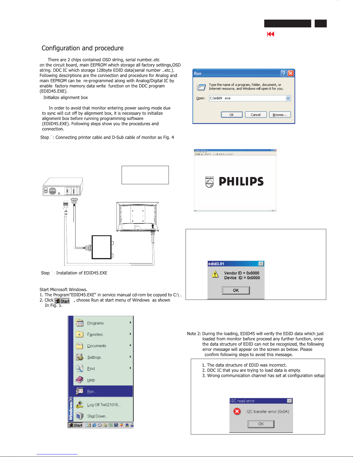
Step 1: After initialize alignment box, connecting all cables and
box as shown in Fig. 10
Fig. 11
Step 2: Read DDC data from monitor
1. Click icon as shown in Fig. 11 from the tool bar to bring up
the Channels "Configuration Setup" windows as shown in Fig. 12.
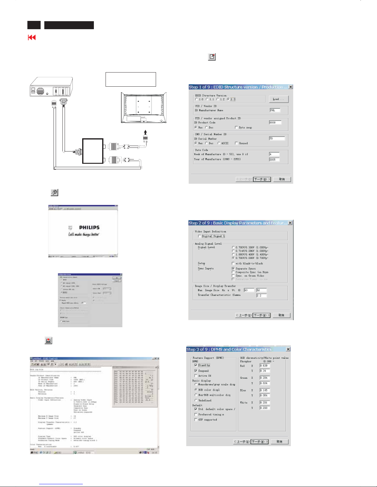
Step 3: Modify DDC data (verify EDID version, week, year)
1. Click (new function) icon from the tool bar, bring up
Step 1 of 9 as shown in Fig. 14 .
EDID45 DDC application provides the function selection and
text change (select & fill out) from Step 1 to Step 9.
Step 4: Modify DDC data (Monitor Serial No.)
Next1. Click , bring up Fig. 15.
2. Click , bring up Fig. 16.Next
3. Click OK button to confirm your selection.
4. Click icon (Read EDID function) to read DDC EDID data from
monitor. The EDID codes will display on screen as shown in Fig. 13.
Fig. 15
Fig. 16
2. Select the DDC2Bi as the communication channel.
As shown in Fig. 12.
Fig. 10
1=Power connector
2= D-SUB connector
PC
To printer port (
L
TP1)
Printer
Port
To
Monitor
ToPC
1
2
----->
----->
Fig. 12
ToPCVideo port (D-sub)
Fig. 13
Fig. 14
Don't close this screen. --->
3138106 10396
 Loading...