

Philips 32PFL3406D/78, 32PFL3606D/78, 32PFL5606D/77, 40PFL5606D/77, 32PFL5606D/78 Service Manual
...
Color Television Chassis
L11M1.1L
LA
19080_000_110301.eps
110329
Contents Page
1. Revision List 2
2. Technical Specifications and Connections 2
3. Precautions, Notes, and Abbreviation List 6
4. Mechanical Instructions 10
5. Service Modes, Error Codes, and Fault Finding 19
6. Alignments 25
7. Circuit Descriptions 28
8. IC Data Sheets 36
9. Block Diagrams
Wiring Diagram 32" (Thriller) 45
Wiring Diagram 40" (Thriller) 46
Wiring Diagram 32" (Berlinale) 47
Wiring Diagram 40" (Berlinale) 48
Block Diagram Video 3939 123 65052 49
Block Diagram Audio 3939 123 65052 50
B01 313912365231 76
B02 313912365231 77
B03 313912365231 79
B04 313912365231 80
B05 313912365231 84
B06 313912365231 86
B07 313912365231 90
313912365231 SSB Layout 91
E 272217190347 Leading Edge Module 93
E 272217190276 KEYBOARD 95
J 272217190275 IR/LED 96
T01 313912365071 98
313912365071 TCON Layout 104
11. Styling Sheets
Styling Sheet Thriller 32" 105
Styling Sheet Thriller 40" 106

Revision List
EN 2 L11M1.1L LA1.
1. Revision List
Manual xxxx xxx xxxx.0
• First release.
Manual xxxx xxx xxxx.1
• Chapter 2: Table 2-1
updated (added Berlinale CTNs).
• Chapter 4: added wiring diagrams; see section 4.1
.
• Chapter 6: added white tone alignment data, see section
6.3
.
• Chapter 7: added Berlinale architecture diagrams; see
section 7.1
.
2. Technical Specifications and Connections
Index of this chapter:
2.1 Technical Specifications
2.2 Directions for Use
2.3 Connections
Notes:
• Figures can deviate due to the different set executions.
• Specifications are indicative (subject to change).
2.1 Technical Specifications
For on-line product support please use the links in Table 2-1.
Here is product information available, as well as getting started,
user manuals, frequently asked questions and software &
drivers.
Table 2-1 Described Model Numbers and Diversity
CTN Styling
SSB 2 4 9 10
3139 123 xxxxx
Connection Overview
Mechanics Block Diagrams Schematics
Wire Dressing
Assembly Removal
LCD Removal
Wiring Diagram
Video
Audio
Control & Clock
I2C
Supply lines
B01 (DC-DC)
B02 (Tuner & Dig. Dem.)
B03 (Class D & mute)
B04 (Power, DDR, LVDS)
B05 (HDMI, USB)
B06 (analog I/O, VGA)
B07 (Hospitality)
E (Keyboard/Leading Edge)
J (IR/LED)
T01 (LVDS Display, TCON
32PFL3406D/78 Thriller
11-1
65052 2-1 4-1 4.3 4.3.2 9-1 9-5 9-6 9-7 9-8 9-9 10-1 10-2 10-3 10-4 10-5 10-6 10-7 10-18 10-19 -
32PFL3606D/78 Thriller
11-1
65052 2-1 4-1 4.3 4.3.2 9-1 9-5 9-6 9-7 9-8 9-9 10-1 10-2 10-3 10-4 10-5 10-6 10-7 10-18 10-19 -
Technical Specifications and Connections
EN 3L11M1.1L LA 2.
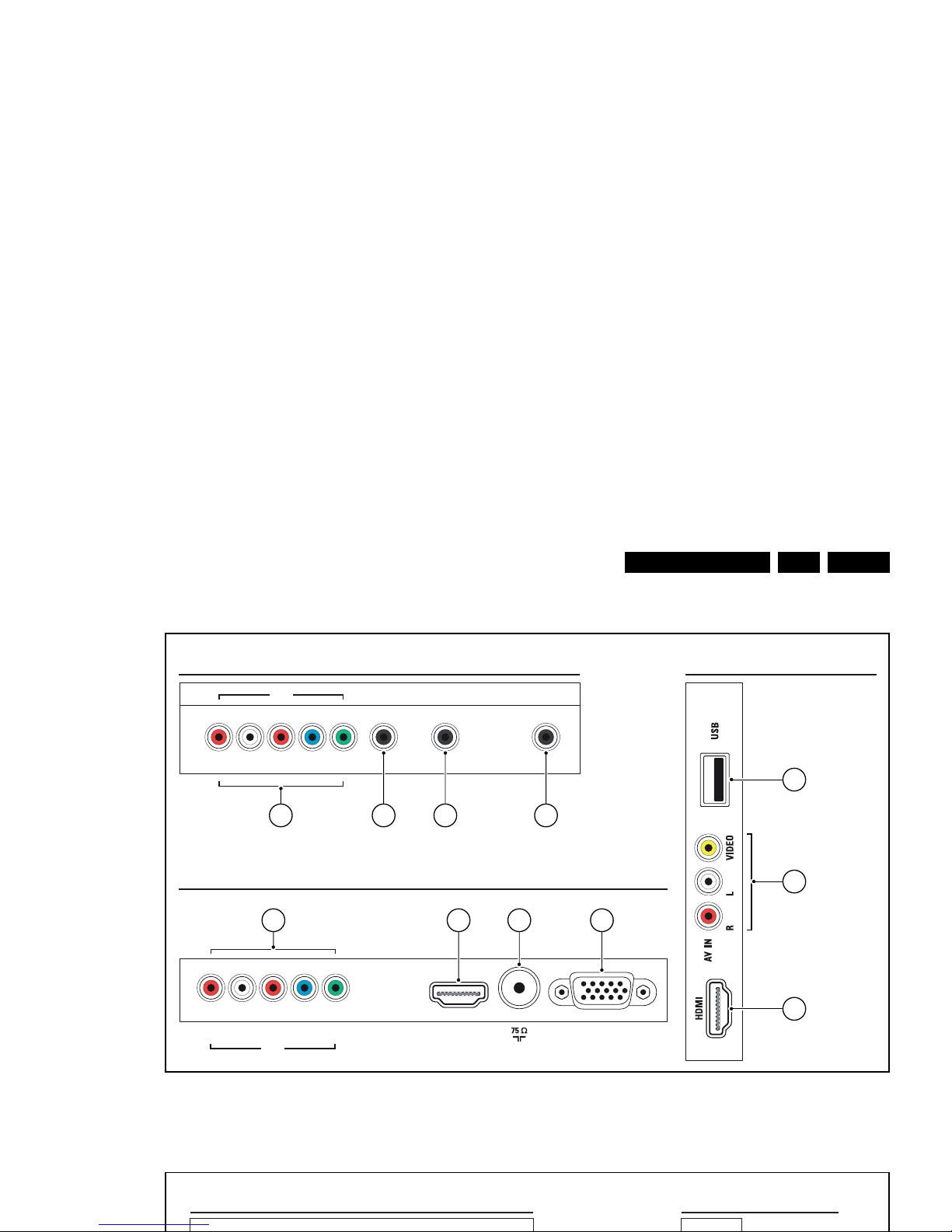
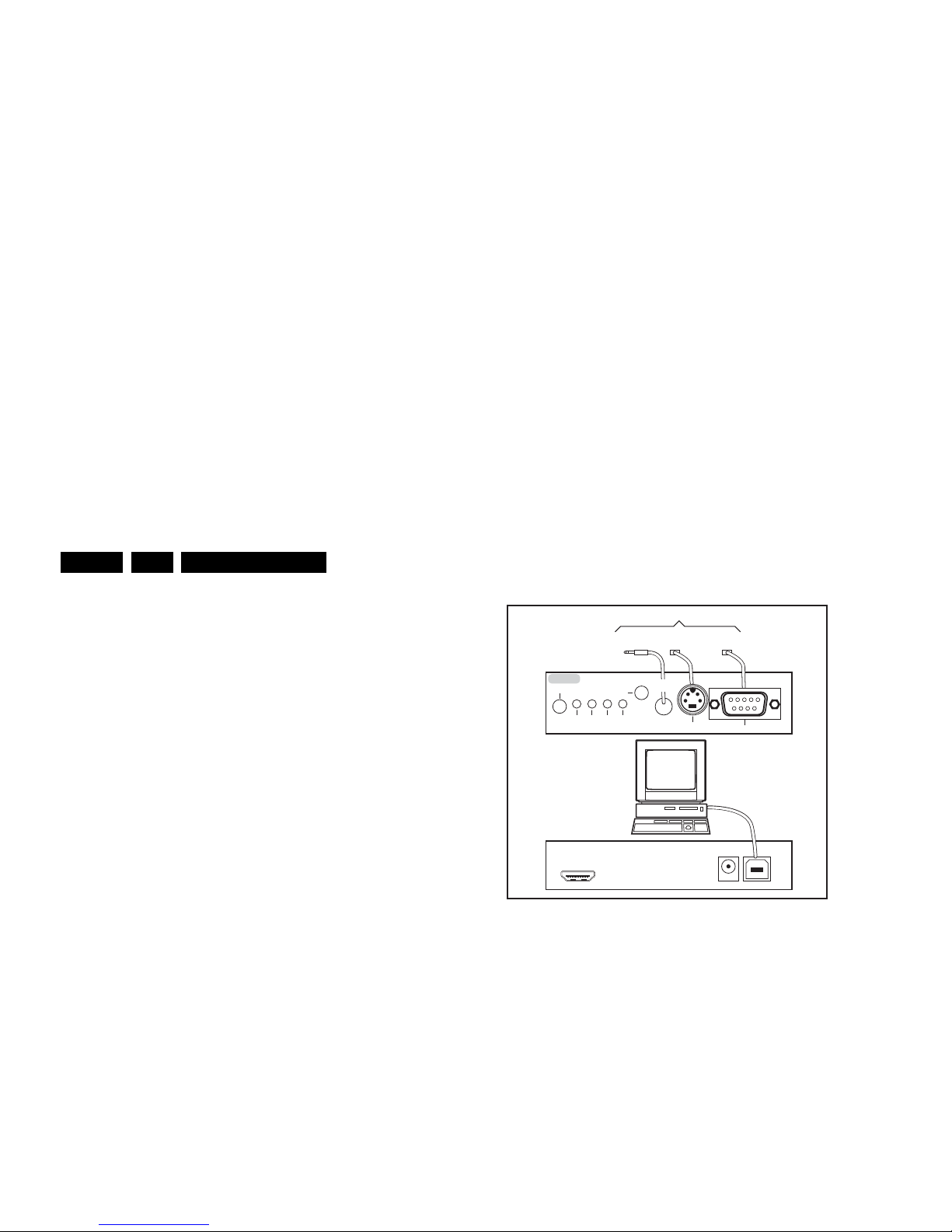
2.3 Connections
Figure 2-1 Connection overview Thriller (xxPFL3x06/xx)
SROTCENNOC EDISSROTCENNOC RAER
DIGITAL
AUDIO OUT
AUDIO IN
DVI/ VGA
SERV.U
R L Pr Pb Y
CVI 1
BOTTOM REAR CONNECTORS
VGA
HDMI 1
(ARC)
R L Pr Pb Y
CVI 2
ANTENNA
19130_001_110421.eps
110421
1
3
2
4 5 6 7
8 9 10 11
SIDE CONNECTORS
REAR CONNECTORS
Technical Specifications and Connections
EN 4 L11M1.1L LA2.
Note: The following connector color abbreviations are used
(according to DIN/IEC 757): Bk= Black, Bu= Blue, Gn= Green,
Gy= Grey, Rd= Red, Wh= White, Ye= Yellow.
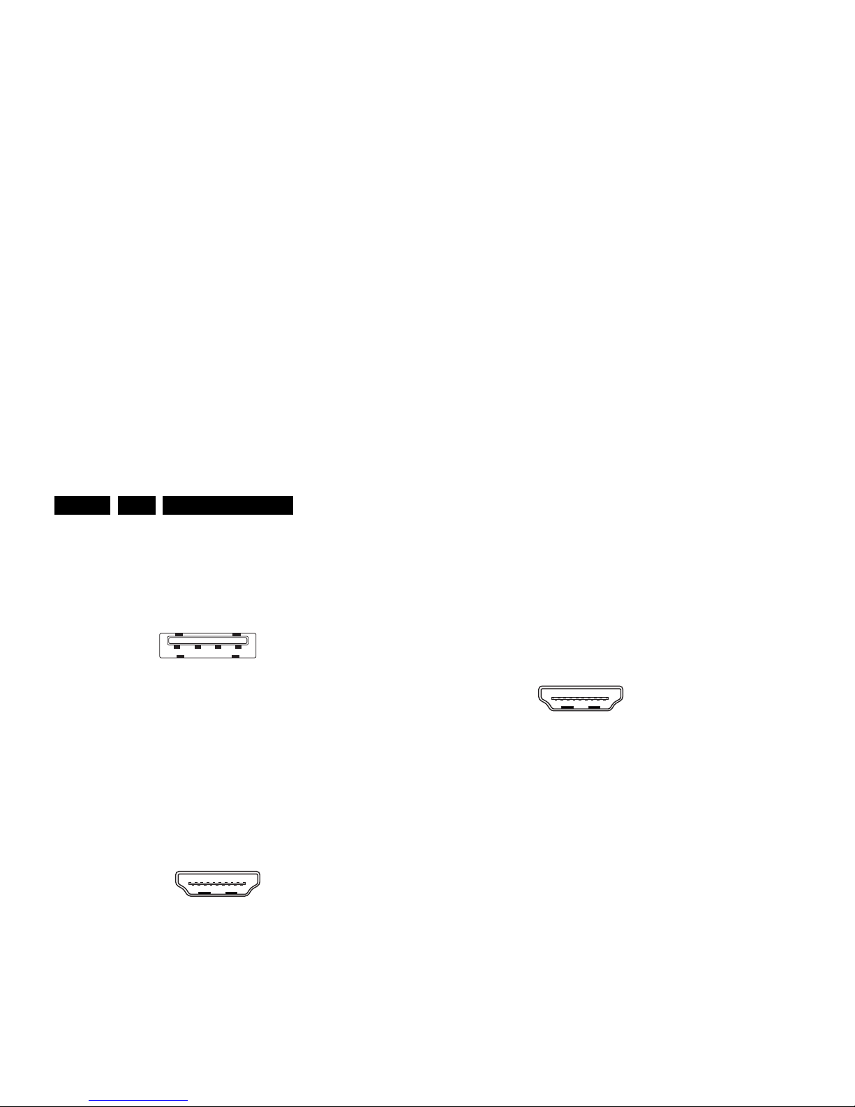
2.3.1 Side Connections
1 - USB2.0
Figure 2-3 USB (type A)
1-+5V k
2 - Data (-) jk
3 - Data (+) jk
4 - Ground Gnd H
2 - AV IN: Cinch: Video CVBS - In, Audio - In
Ye - Video CVBS 1 V
PP
/ 75 ohm jq
Wh - Audio L 0.5 V
RMS
/ 10 kohm jq
Rd - Audio R 0.5 V
RMS
/ 10 kohm jq
3 - HDMI: Digital Video, Digital Audio - In
Figure 2-4 HDMI (type A) connector
1 - D2+ Data channel j
2 - Shield Gnd H
3 - D2- Data channel j
4 - D1+ Data channel j
5 - Shield Gnd H
6 - D1- Data channel j
7 - D0+ Data channel j
8 - Shield Gnd H
9 - D0- Data channel j
10 - CLK+ Data channel j
11 - Shield Gnd H
2.3.3 Bottom Connections
8 - CVI-2: Cinch: Video YPbPr - In, Audio - In
Wh - Audio - L 0.5 V
RMS
/ 10 k jq
Rd - Audio - R 0.5 V
RMS
/ 10 k jq
Rd - Video Pr 0.7 V
PP
/ 75 jq
Bu - Video Pb 0.7 V
PP
/ 75 jq
Gn - Video Y 1 V
PP
/ 75 jq
9 - HDMI1 Audio Return Channel: Digital Video, Digital
Audio - In
Figure 2-5 HDMI (type A) connector
1 - D2+ Data channel j
2 - Shield Gnd H
3 - D2- Data channel j
4 - D1+ Data channel j
5 - Shield Gnd H
6 - D1- Data channel j
7 - D0+ Data channel j
8 - Shield Gnd H
9 - D0- Data channel j
10 - CLK+ Data channel j
11 - Shield Gnd H
12 - CLK- Data channel j
13 - Easylink Control channel/CEC jk
14 - ARC Audio Return Channel j
15 - DDC_SCL DDC clock j
16 - DDC_SDA DDC data jk
17 - Ground Gnd H
18 - +5V j
19 - HPD Hot Plug Detect j
20 - Ground Gnd H
10 - Aerial - In
- - F-type Coax, 75 D
11 - VGA: Video RGB - In
1 2 3 4
10000_022_090121.eps
090121
10000_017_090121.eps
090428
19
1
18 2
10000_017_090121.eps
090428
19
1
18 2

Technical Specifications and Connections
EN 5L11M1.1L LA 2.
1 - D2+ Data channel j
2-Shield Gnd H
3 - D2- Data channel j
4 - D1+ Data channel j
5-Shield Gnd H
6 - D1- Data channel j
7 - D0+ Data channel j
8-Shield Gnd H
9 - D0- Data channel j
10 - CLK+ Data channel j
11 - Shield Gnd H
12 - CLK- Data channel j
13 - Easylink Control channel/CEC jk
14 - n.c.
15 - DDC_SCL DDC clock j
16 - DDC_SDA DDC data jk
17 - Ground Gnd H
18 - +5V j
19 - HPD Hot Plug Detect j
20 - Ground Gnd H

Precautions, Notes, and Abbreviation List
EN 6 L11M1.1L LA3.
3. Precautions, Notes, and Abbreviation List
Index of this chapter:
3.1 Safety Instructions
3.2 Warnings
3.3 Notes
3.4 Abbreviation List
3.1 Safety Instructions
Safety regulations require the following during a repair:
• Connect the set to the Mains/AC Power via an isolation
transformer (> 800 VA).
• Replace safety components, indicated by the symbol h,
only by components identical to the original ones. Any
other component substitution (other than original type) may
increase risk of fire or electrical shock hazard.
Safety regulations require that after a repair, the set must be
returned in its original condition. Pay in particular attention to
the following points:
• Route the wire trees correctly and fix them with the
mounted cable clamps.
• Check the insulation of the Mains/AC Power lead for
external damage.
• Check the strain relief of the Mains/AC Power cord for
proper function.
• Check the electrical DC resistance between the Mains/AC
Power plug and the secondary side (only for sets that have
a Mains/AC Power isolated power supply):
1. Unplug the Mains/AC Power cord and connect a wire
between the two pins of the Mains/AC Power plug.
2. Set the Mains/AC Power switch to the “on” position
(keep the Mains/AC Power cord unplugged!).
3. Measure the resistance value between the pins of the
Mains/AC Power plug and the metal shielding of the
tuner or the aerial connection on the set. The reading
should be between 4.5 M and 12 M.
4. Switch “off” the set, and remove the wire between the
two pins of the Mains/AC Power plug.
• Check the cabinet for defects, to prevent touching of any
inner parts by the customer.
• Where necessary, measure the waveforms and voltages
with (D) and without (E) aerial signal. Measure the
voltages in the power supply section both in normal
operation (G) and in stand-by (F). These values are
indicated by means of the appropriate symbols.
3.3.2 Schematic Notes
• All resistor values are in ohms, and the value multiplier is
often used to indicate the decimal point location (e.g. 2K2
indicates 2.2 k).
• Resistor values with no multiplier may be indicated with
either an “E” or an “R” (e.g. 220E or 220R indicates 220 ).
• All capacitor values are given in micro-farads (10
-6
),
nano-farads (n 10
-9
), or pico-farads (p 10
-12
).
• Capacitor values may also use the value multiplier as the
decimal point indication (e.g. 2p2 indicates 2.2 pF).
• An “asterisk” (*) indicates component usage varies. Refer
to the diversity tables for the correct values.
• The correct component values are listed on the Philips
Spare Parts Web Portal.
3.3.3 Spare Parts
For the latest spare part overview, consult your Philips Spare
Part web portal.
3.3.4 BGA (Ball Grid Array) ICs
Introduction
For more information on how to handle BGA devices, visit this
URL: http://www.atyourservice-magazine.com
. Select
“Magazine”, then go to “Repair downloads”. Here you will find
Information on how to deal with BGA-ICs.
BGA Temperature Profiles
For BGA-ICs, you must use the correct temperature-profile.
Where applicable and available, this profile is added to the IC
Data Sheet information section in this manual.

Precautions, Notes, and Abbreviation List
EN 7L11M1.1L LA 3.
The third digit in the serial number (example:
AG2B0335000001) indicates the number of the alternative
B.O.M. (Bill Of Materials) that has been used for producing the
specific TV set. In general, it is possible that the same TV
model on the market is produced with e.g. two different types
of displays, coming from two different suppliers. This will then
result in sets which have the same CTN (Commercial Type
Number; e.g. 28PW9515/12) but which have a different B.O.M.
number.
By looking at the third digit of the serial number, one can
identify which B.O.M. is used for the TV set he is working with.
If the third digit of the serial number contains the number “1”
(example: AG1B033500001), then the TV set has been
manufactured according to B.O.M. number 1. If the third digit is
a “2” (example: AG2B0335000001), then the set has been
produced according to B.O.M. no. 2. This is important for
ordering the correct spare parts!
For the third digit, the numbers 1...9 and the characters A...Z
can be used, so in total: 9 plus 26= 35 different B.O.M.s can be
indicated by the third digit of the serial number.
Identification: The bottom line of a type plate gives a 14-digit
serial number. Digits 1 and 2 refer to the production centre (e.g.
SN is Lysomice, RJ is Kobierzyce), digit 3 refers to the B.O.M.
code, digit 4 refers to the Service version change code, digits 5
and 6 refer to the production year, and digits 7 and 8 refer to
production week (in example below it is 2010 week 10 / 2010
week 17). The 6 last digits contain the serial number.
powered TV set, it is best to test the high voltage insulation.
It is easy to do, and is a good service precaution.
3.4 Abbreviation List
0/6/12 SCART switch control signal on A/V
board. 0 = loop through (AUX to TV),
6 = play 16 : 9 format, 12 = play 4 : 3
format
AARA Automatic Aspect Ratio Adaptation:
algorithm that adapts aspect ratio to
remove horizontal black bars; keeps
the original aspect ratio
ACI Automatic Channel Installation:
algorithm that installs TV channels
directly from a cable network by
means of a predefined TXT page
ADC Analogue to Digital Converter
AFC Automatic Frequency Control: control
signal used to tune to the correct
frequency
AGC Automatic Gain Control: algorithm that
controls the video input of the feature
box
AM Amplitude Modulation
AP Asia Pacific
AR Aspect Ratio: 4 by 3 or 16 by 9
ASF Auto Screen Fit: algorithm that adapts
aspect ratio to remove horizontal black
bars without discarding video
information
ATSC Advanced Television Systems
Committee, the digital TV standard in
the USA
ATV See Auto TV
Auto TV A hardware and software control
system that measures picture content,
and adapts image parameters in a
dynamic way
AV External Audio Video
AVC Audio Video Controller
AVIP Audio Video Input Processor
B/G Monochrome TV system. Sound

Precautions, Notes, and Abbreviation List
EN 8 L11M1.1L LA3.
D/K Monochrome TV system. Sound
carrier distance is 6.5 MHz
DFI Dynamic Frame Insertion
DFU Directions For Use: owner's manual
DMR Digital Media Reader: card reader
DMSD Digital Multi Standard Decoding
DNM Digital Natural Motion
DNR Digital Noise Reduction: noise
reduction feature of the set
DRAM Dynamic RAM
DRM Digital Rights Management
DSP Digital Signal Processing
DST Dealer Service Tool: special remote
control designed for service
technicians
DTCP Digital Transmission Content
Protection; A protocol for protecting
digital audio/video content that is
traversing a high speed serial bus,
such as IEEE-1394
DVB-C Digital Video Broadcast - Cable
DVB-T Digital Video Broadcast - Terrestrial
DVD Digital Versatile Disc
DVI(-d) Digital Visual Interface (d= digital only)
E-DDC Enhanced Display Data Channel
(VESA standard for communication
channel and display). Using E-DDC,
the video source can read the EDID
information form the display.
EDID Extended Display Identification Data
(VESA standard)
EEPROM Electrically Erasable and
Programmable Read Only Memory
EMI Electro Magnetic Interference
EPG Electronic Program Guide
EPLD Erasable Programmable Logic Device
EU Europe
EXT EXTernal (source), entering the set by
SCART or by cinches (jacks)
FDS Full Dual Screen (same as FDW)
FDW Full Dual Window (same as FDS)
FLASH FLASH memory
FM Field Memory or Frequency
Modulation
subcommittee of the International
Telecommunication Union relating to
radio communication. ITU-656 (a.k.a.
SDI), is a digitized video format used
for broadcast grade video.
Uncompressed digital component or
digital composite signals can be used.
The SDI signal is self-synchronizing,
uses 8 bit or 10 bit data words, and has
a maximum data rate of 270 Mbit/s,
with a minimum bandwidth of 135
MHz.
iTV Institutional TeleVision; TV sets for
hotels, hospitals etc.
LS Last Status; The settings last chosen
by the customer and read and stored
in RAM or in the NVM. They are called
at start-up of the set to configure it
according to the customer's
preferences
LATAM Latin America
LCD Liquid Crystal Display
LED Light Emitting Diode
L/L' Monochrome TV system. Sound
carrier distance is 6.5 MHz. L' is Band
I, L is all bands except for Band I
LPL LG.Philips LCD (supplier)
LS Loudspeaker
LVDS Low Voltage Differential Signalling
Mbps Mega bits per second
M/N Monochrome TV system. Sound
carrier distance is 4.5 MHz
MHEG Part of a set of international standards
related to the presentation of
multimedia information, standardised
by the Multimedia and Hypermedia
Experts Group. It is commonly used as
a language to describe interactive
television services
MIPS Microprocessor without Interlocked
Pipeline-Stages; A RISC-based
microprocessor
MOP Matrix Output Processor
MOSFET Metal Oxide Silicon Field Effect

Precautions, Notes, and Abbreviation List
EN 9L11M1.1L LA 3.
PAL Phase Alternating Line. Color system
mainly used in West Europe (colour
carrier = 4.433619 MHz) and South
America (colour carrier
PAL M = 3.575612 MHz and
PAL N = 3.582056 MHz)
PCB Printed Circuit Board (same as “PWB”)
PCM Pulse Code Modulation
PDP Plasma Display Panel
PFC Power Factor Corrector (or Pre-
conditioner)
PIP Picture In Picture
PLL Phase Locked Loop. Used for e.g.
FST tuning systems. The customer
can give directly the desired frequency
POD Point Of Deployment: a removable
CAM module, implementing the CA
system for a host (e.g. a TV-set)
POR Power On Reset, signal to reset the uP
PSDL Power Supply for Direct view LED
backlight with 2D-dimming
PSL Power Supply with integrated LED
drivers
PSLS Power Supply with integrated LED
drivers with added Scanning
functionality
PTC Positive Temperature Coefficient,
non-linear resistor
PWB Printed Wiring Board (same as “PCB”)
PWM Pulse Width Modulation
QRC Quasi Resonant Converter
QTNR Quality Temporal Noise Reduction
QVCP Quality Video Composition Processor
RAM Random Access Memory
RGB Red, Green, and Blue. The primary
color signals for TV. By mixing levels
of R, G, and B, all colors (Y/C) are
reproduced.
RC Remote Control
RC5 / RC6 Signal protocol from the remote
control receiver
RESET RESET signal
ROM Read Only Memory
RSDS Reduced Swing Differential Signalling
SSC Spread Spectrum Clocking, used to
reduce the effects of EMI
STB Set Top Box
STBY STand-BY
SVGA 800 × 600 (4:3)
SVHS Super Video Home System
SW Software
SWAN Spatial temporal Weighted Averaging
Noise reduction
SXGA 1 280 × 1024
TFT Thin Film Transistor
THD Total Harmonic Distortion
TMDS Transmission Minimized Differential
Signalling
TS Transport Stream
TXT TeleteXT
TXT-DW Dual Window with TeleteXT
UI User Interface
uP Microprocessor
UXGA 1600 × 1200 (4:3)
V V-sync to the module
VESA Video Electronics Standards
Association
VGA 640 × 480 (4:3)
VL Variable Level out: processed audio
output toward external amplifier
VSB Vestigial Side Band; modulation
method
WYSIWYR What You See Is What You Record:
record selection that follows main
picture and sound
WXGA 1 280 × 768 (15:9)
XTAL Quartz crystal
XGA 1024 × 768 (4:3)
Y Luminance signal
Y/C Luminance (Y) and Chrominance (C)
signal
YPbPr Component video. Luminance and
scaled color difference signals (B-Y
and R-Y)
YUV Component video
Mechanical Instructions
EN 10 L11M1.1L LA4.
4. Mechanical Instructions
Index of this chapter:
4.1 Cable Dressing
4.2 Service Positions
4.3 Assy/Panel Removal (Thriller styling; xxPFL3x06D/xx)
4.4 Assy/Panel Removal (Berlinale styling; xxPFL5x06D/xx)
4.5 Set Re-assembly
Notes:
• Figures below can deviate slightly from the actual situation,
due to the different set executions.
4.1 Cable Dressing
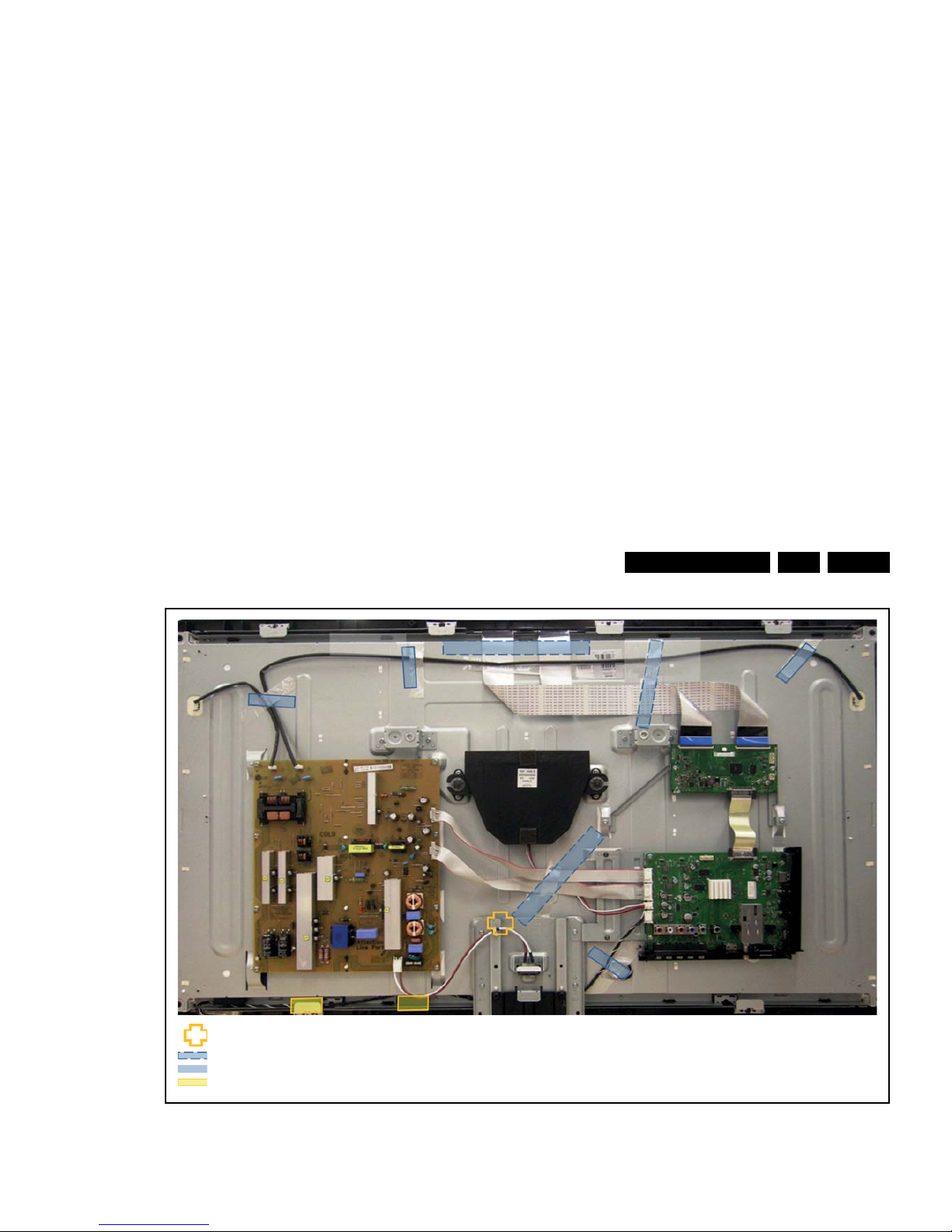
Mechanical Instructions
EN 11L11M1.1L LA 4.
Figure 4-2 Cable dressing 40" Thriller (xxPFL3x06D/xx)
19130_003_110426.eps
110426
11 mm saddle × 1
150 mm tape × 3
70 mm tape × 4
Foam × 2
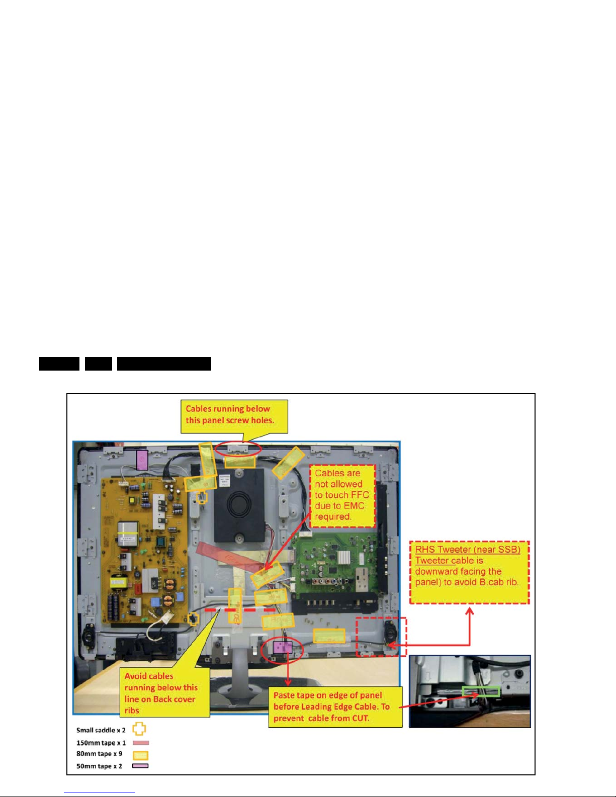
Mechanical Instructions
EN 12 L11M1.1L LA4.
19131_025_110623.eps
110623
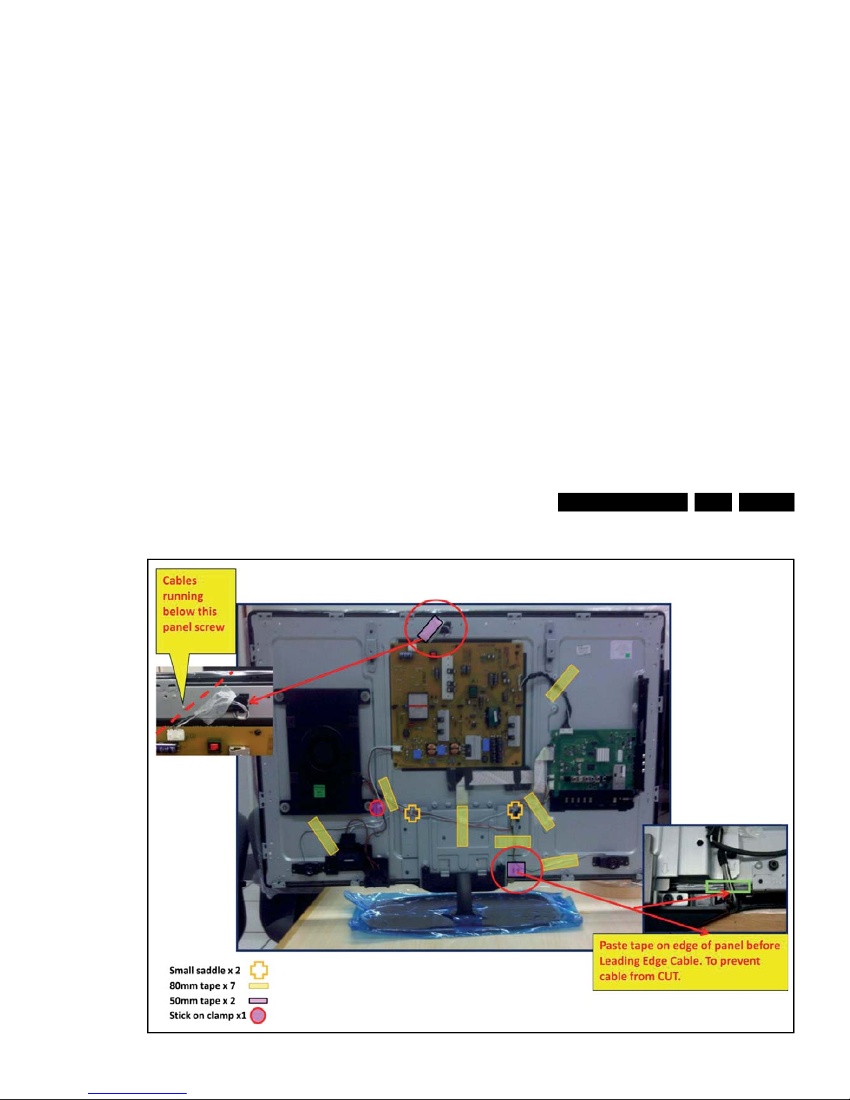
Mechanical Instructions
EN 13L11M1.1L LA 4.
Figure 4-4 Cable dressing 40" Berlinale (xxPFL5x06D/xx)
19131_026_110623.eps
110623
Mechanical Instructions
EN 14 L11M1.1L LA4.
4.2 Service Positions
For easy servicing of a TV set, the set should be put face down
on a soft flat surface, foam buffers or other specific workshop
tools. Ensure that a stable situation is created to perform
measurements and alignments. When using foam bars take
care that these always support the cabinet and never only the
display. Caution: Failure to follow these guidelines can
seriously damage the display!
Ensure that ESD safe measures are taken.
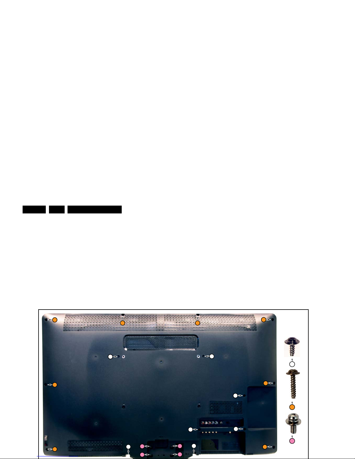
4.3 Assy/Panel Removal (Thriller styling;
xxPFL3x06D/xx)
Instructions below apply to the 40PFL3606D/78, but will be
similar for other models.
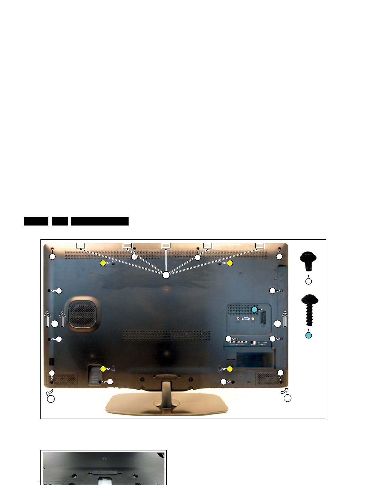
4.3.1 Rear Cover
3
2
1
3
3
2 2
3
2
2
3
3
3
3
2
1
1
2
32
32
1
1
3
Mechanical Instructions
EN 15L11M1.1L LA 4.
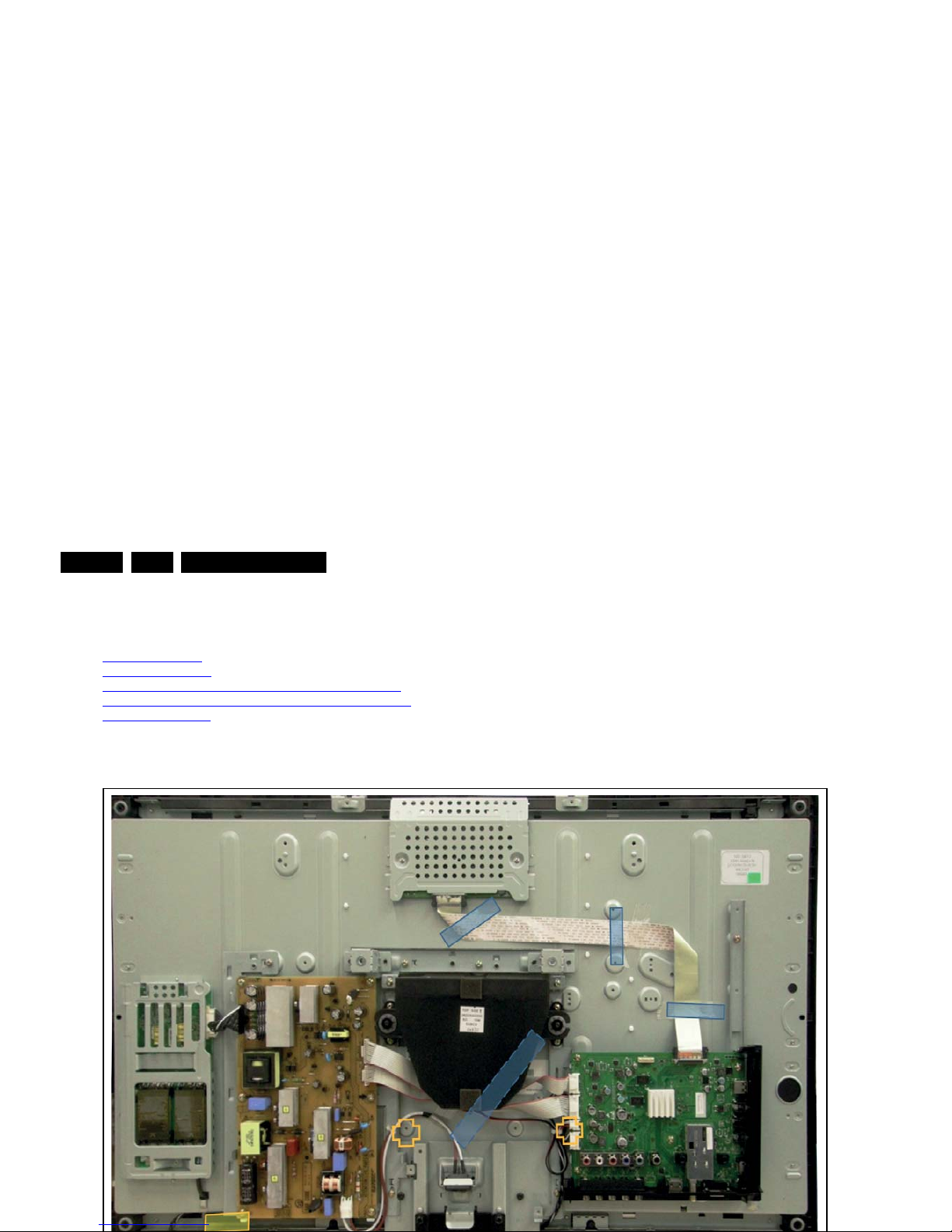
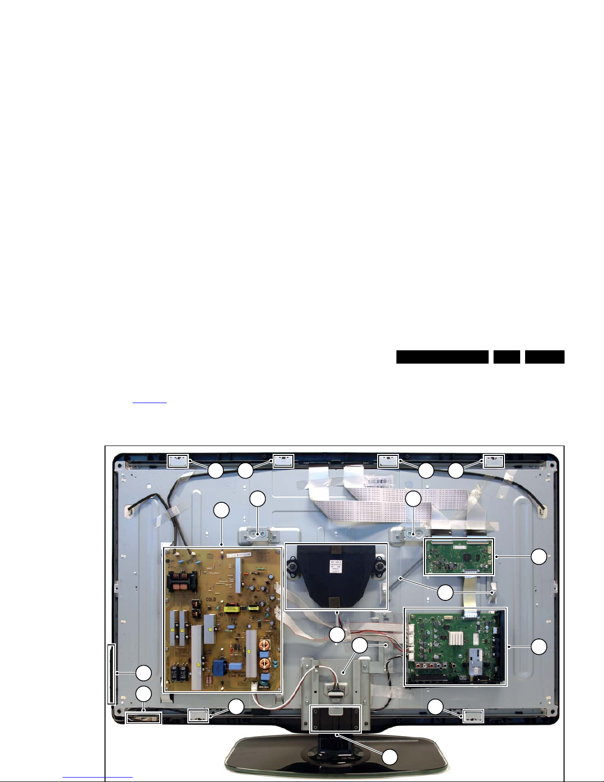
4.3.2 LCD Panel
Refer to Figure 4-6
for details.
1. Remove the Stand [A].
2. Remove the Speakers/Subwoofer [B].
3. Remove the PSU [C], SSB [D] and TCON (E).
4. Remove the IR/LED board [F].
5. Remove the Local Control board [G].
6. Remove the clamps [1].
7. Remove all metal subframes [2] that do not belong to the
LCD display.
1A
1B
1C
12 12
12
12
D
E
F
1
1
1111
G
Mechanical Instructions
EN 16 L11M1.1L LA4.
Figure 4-7 Rear cover removal -1-
4.4.2 Small Signal Board (SSB)
Caution: it is mandatory to remount all different screws at their
original position during re-assembly. Failure to do so may result
in damaging the SSB.
1. Release the clips from both the LVDS Flat Foil connectors
that connect with the SSB.
19150_006_110512.eps
110512
6
22
2
3
2
2
2
2
1
1
1
1
2
2
2
3
2
2
2
2
8
7
8
7
Mechanical Instructions
EN 17L11M1.1L LA 4.
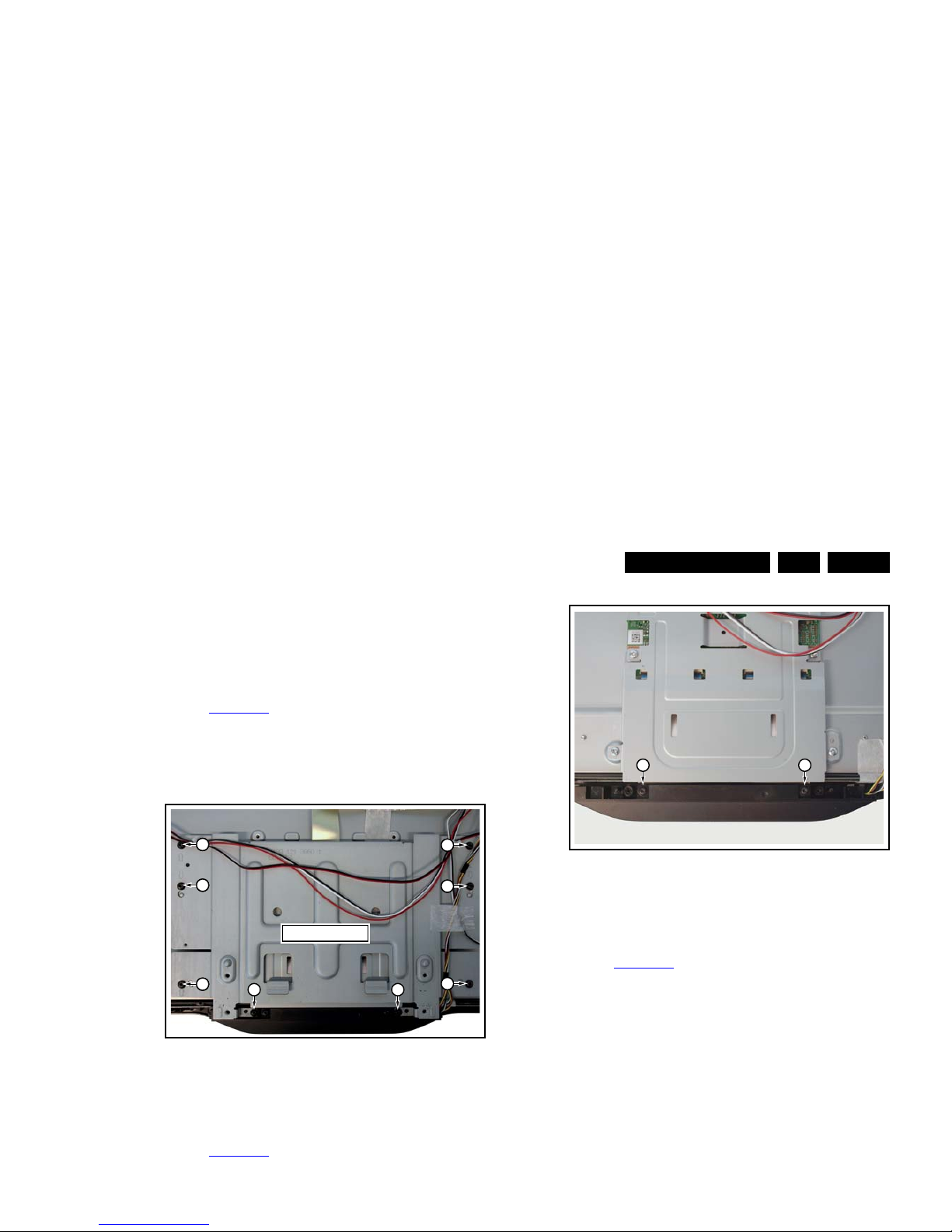
4.4.4 Stand removal
1. Remove the four fixation screws.
2. Take the stand out in a downwards direction.
4.4.5 Stand bracket removal
Refer to Figure 4-10
for details.
Caution: it is mandatory to remount all different screws at their
original position during re-assembly. Be sure to put the set in
the Service Position.
1. Remove the fixation screws [1], [2].
2. Take the Stand bracket out.
Figure 4-10 Stand bracket removal
4.4.6 Power switch and mains plug
Refer to Figure 4-11
for details.
1. Unplug the connector from the PSU.
2. The switch and mains inlet can be removed by lifting the
catches with a screwdriver [1] and sliding them out [2].
When defective, replace the power switch and mains plug
assembly.
Figure 4-12 IR/LED/Keyboard removal
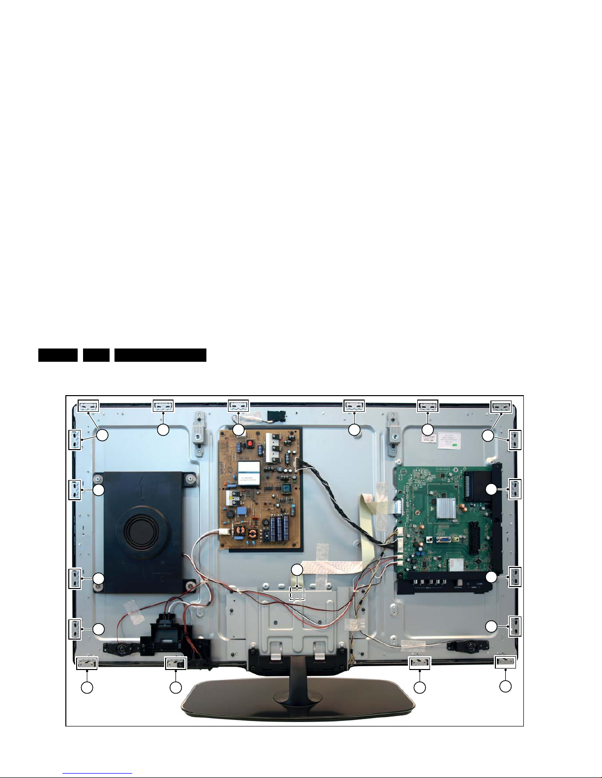
4.4.8 LCD Panel
Refer to Figure 4-14
for details.
1. Remove the SSB as described earlier.
2. Remove the PSU as described earlier.
3. Remove the stand as described earlier.
4. Remove the stand bracket as described earlier.
5. Remove the Power switch and mains plug as described
earlier and remove the plastic subframe.
6. Remove the speakers.
7. Remove all tapes that secure any cable and remove the
cables from the set.
8. Release the clips from the LVDS flat
foil connector [1].
Caution: be careful, as these are very fragile cables and
connectors! Take the flat foil out of it’s connector.
9. Release the metal clips [2] at the top, sides and bottom of
the panel that secure the LCD panel with the bezel and
remove the clips from their position. Be careful not to break
the plastic catches [3] that secure the metal brackets.
10. Lift the LED Panel from the bezel.
19150_007_110512.eps
110512
1 1
Stand Bracket
3
2
2
2
2
32
32
19150_009_110512.eps
110512
1 1
Mechanical Instructions
EN 18 L11M1.1L LA4.
Figure 4-14 LCD Panel removal -2-
19150_011_110512.eps
110512
1
22
2 2 2
2
2 2
2
2
2
2
2
2
2
2

Service Modes, Error Codes, and Fault Finding
EN 19L11M1.1L LA 5.
5. Service Modes, Error Codes, and Fault Finding
Index of this chapter:
5.1 Test Points
5.2 Service Modes
5.3 Service Tools
5.4 Error Codes
5.5 The Blinking LED Procedure
5.6 Fault Finding and Repair Tips
5.7 Repair Policy TCON Boards
5.8 Software Upgrading
5.1 Test Points
In the chassis schematics and layout overviews, the test points
are mentioned. In the schematics and layouts, test points are
indicated with “Fxxx” or “Ixxx”.
As most signals are digital, it will be difficult to measure
waveforms with a standard oscilloscope. Several key ICs are
capable of generating test patterns, which can be controlled via
ComPair. In this way it is possible to determine which part is
defective.
Perform measurements under the following conditions:
• Service Default Mode.
• Video: Color bar signal.
• Audio: 3 kHz left, 1 kHz right.
5.2 Service Modes
The Service Mode feature is split into four parts:
• Service Default Mode (SDM).
• Service Alignment Mode (SAM).
• Customer Service Mode (CSM).
• Computer Aided Repair Mode (ComPair).
SDM and SAM offer features, which can be used by the Service
engineer to repair/align a TV set. Some features are:
• A pre-defined situation to ensure measurements can be
made under uniform conditions (SDM).
• Activates the blinking LED procedure for error identification
5.2.1 General
Next items are applicable to all Service Modes or are general.
Life Timer
During the life time cycle of the TV set, a timer is kept (called
“Op. Hour”). It counts the normal operation hours (not the
Stand-by hours). The actual value of the timer is displayed in
SDM and SAM in a decimal value. Every two soft-resets
increase the hour by +1. Stand-by hours are not counted.
Software Identification, Version, and Cluster
The software ID, version, and cluster will be shown in the main
menu display of SDM, SAM, and CSM.
The screen will show: “AAAAAAB-XX.YY”, where:
• AAAAAA is the chassis name: L11M11.
• B is the region indication: E= Europe, A= AP/China, U=
NAFTA, L= LATAM.
• XX is the main version number: this is updated with a major
change of specification (incompatible with the previous
software version). Numbering will go from 01 - 99 and AA ZZ.
– If the main version number changes, the new version
number is written in the NVM.
– If the main version number changes, the default
settings are loaded.
• YY is the sub version number: this is updated with a minor
change (backwards compatible with the previous versions)
Numbering will go from 00 - 99.
– If the sub version number changes, the new version
number is written in the NVM.
– If the NVM is fresh, the software identification, version,
and cluster will be written to NVM.
Display Option Code Selection
When after an SSB or display exchange, the display option
code is not set properly, it will result in a TV with “no display”.
Therefore, it is required to set this display option code after
such a repair.
To do so, press the following key sequence on a standard RC

Service Modes, Error Codes, and Fault Finding
EN 20 L11M1.1L LA5.
5.2.2 Service Default Mode (SDM)
Purpose
Set the TV in SDM mode in order to be able to create a predefined setting for measurements to be made. In this platform,
a simplified SDM is introduced (without protection override and
without tuning to a predefined frequency).
Specifications
• Set linear video and audio settings to 50%, but volume to
25%. Stored user settings are not affected.
• Set Smart Picture to “Game”.
• Set Smart Sound to “Standard”.
• Tune channel to:
- for analogue SDM: channel 3 (61.25 MHz)
- for digital SDM: channel 26 (545.143 MHz).
• For digital SDM: set PID default from the stream.
• All service-unfriendly modes (if present) are disabled, since
they interfere with diagnosing/repairing a set. These
service unfriendly modes are:
– (Sleep) timer.
– Blue mute/Wall paper.
– Auto switch “off” (when there is no “ident” signal).
– Hotel or hospital mode.
– Child lock or parental lock (manual or via V-chip).
– Skipping, blanking of “Not favorite”, “Skipped” or
“Locked” presets/channels.
– Automatic storing of Personal Preset or Last Status
settings.
– Automatic user menu time-out (menu switches back/
OFF automatically.
– Auto Volume levelling (AVL).
How to Activate
To activate analogue SDM, use one of the following methods:
• Press the following key sequence on the RC transmitter:
“062596” directly followed by the MENU button.
• Short one of the “Service” pads on the TV board during cold
start (see Figure 5-2
). Then press the mains button
(remove the short after start-up).
Caution: When doing this, the service-technician must
know exactly what he is doing, as it could damage the
television set.
• ERR: Shows all errors detected since the last time the
buffer was erased in format <xxx> <xxx> <xxx> <xxx>
<xxx> (five errors possible).
• OP: Used to read-out the option bytes. Ten codes (in two
rows) are possible.
How to Navigate
As this mode is read only, there is not much to navigate. To
switch to other modes, use one of the following methods:
• Command MENU from the user remote will enter the
normal user menu (brightness, contrast, color, etc...) with
“SDM” OSD remaining, and pressing MENU key again will
return to the last status of SDM again.
• To prevent the OSD from interfering with measurements in
SDM, command “OSD” or “i+” (“STATUS” or “INFO” for
NAFTA and LATAM) from the user remote will toggle the
OSD “on/off” with “SDM” OSD remaining always “on”.
• Press the following key sequence on the remote control
transmitter: “062596” directly followed by the INFO[i+]/OK
button to switch to SAM (do not allow the display to time out
between entries while keying the sequence).
How to Exit
Switch the set to Stand-by by
• pressing the standby button on the remote control
transmitter or on the television set, or
• via a standard RC-transmitter by keying the “00” sequence.
If you switch the television set “off” by removing the mains (i.e.,
unplugging the television), the television set will remain in SDM
when mains is re-applied, and the error buffer is not cleared.
The error buffer will only be cleared when the “clear” command
is used in the SAM menu.
Note:
• If the TV is switched “off” by a power interrupt while in SDM,
the TV will show up in the last status of SDM menu as soon
as the power is supplied again. The error buffer will not be
cleared.
• In case the set is accidentally in Factory mode (with an “F”
displayed on the screen), pressing and holding “VOL-“
button for 5 seconds and then followed by pressing and
holding the “CH-” button for another 5 seconds should exit
the Factory mode.

Service Modes, Error Codes, and Fault Finding
EN 21L11M1.1L LA 5.
Menu items and explanation:
1. System Information.
• Op Hour: This represents the life timer. The timer
counts normal operation hours, but does not count
Stand-by hours.
• MAIN SW ID: See paragraph Software Identification,
Version, and Cluster for the SW name definition.
• ERR: Shows all errors detected since the last time the
buffer was erased. Five errors possible.
• OP1/OP2: Used to read-out the option bytes. See
paragraph 6.7 Option Settings
in the Alignments
section for a detailed description. Ten codes are
possible.
2. Tuner.
• AGC Adjustment: See paragraph 6.3.1
for
instructions.
• Store: To store the data.
3. Clear. Erases the contents of the error buffer. Select this
menu item and press the MENU RIGHT key on the remote
control. The content of the error buffer is cleared.
4. Options. To set the option bits. See paragraph 6.7 Option
Settings in the “Alignments” chapter for a detailed
description.
5. RGB Align. To align the White Tone. See White Tone
Alignment: for a detailed description.
6. NVM Editor. To change the NVM data in the television set.
See also paragraph 5.6 Fault Finding and Repair Tips
.
7. Upload to USB.
8. Download from USB.
9. Initialise NVM. To initialize a (corrupted) NVM. Be careful,
this will erase all settings!
10. Auto ADC. Refer to chapter 6. Alignments
for detailed
information.
11. EDID Write Enable. Enables EDID writing (not applicable
to Berlinale sets).
12. Service Data. Virtual Key board for character input entry.
How to Navigate
• In the SAM menu, select menu items with the UP/DOWN
keys on the remote control transmitter. The selected item
will be indicated. When not all menu items fit on the screen,
use the UP/DOWN keys to display the next / previous
menu items.
soon as the power is supplied again. The error buffer will
not be cleared.
• In case the set is in Factory mode by accident (with “F”
displayed on screen), pressing and holding “VOL-“ button
for 5 seconds and then followed by pressing and holding
the “CH-” button for another 5 seconds should exit the
Factory mode.
5.2.4 Customer Service Mode (CSM)
Purpose
The Customer Service Mode shows error codes and
information on the TV’s operation settings. A call centre can
instruct the customer (by telephone) to enter CSM in order to
identify the status of the set. This helps them to diagnose
problems and failures in the TV before making a service call.
The CSM is a read-only mode; therefore, modifications are not
possible in this mode.
Specifications
• Ignore “Service unfriendly modes”.
• Set volume to 25%.
• Set Smart Picture to “Game”.
• Set Smart Sound to “Standard”.
• Line number for every line (to make CSM language
independent).
• Set the screen mode to full screen (all contents on screen
is visible).
• After leaving the Customer Service Mode, the original
settings are restored.
• Possibility to use “CH+” or “CH-” for channel surfing, or
enter the specific channel number on the RC.
How to Activate
To activate CSM, press the following key sequence on a
standard remote control transmitter: “123654” (do not allow the
display to time out between entries while keying the sequence).
After entering the Customer Service Mode, the following items
are displayed:
Menu Explanation CSM1
1. Set Type. Type number, e.g. 32PFL3605/78. (*)
Service Modes, Error Codes, and Fault Finding
EN 22 L11M1.1L LA5.
3. HDCP Keys. Indicates if the HDMI keys (or HDCP keys)
are valid or not. Not applicable to Berlinale series.
4. not used
5. not used
6. not used
7. not used.
Create a CSM dump on an USB stick
There will be CSM dump to a plugged in USB-stick upon
entering CSM-mode. An extended CSM dump will be created
when the “OK” button on RC is pressed in CSM while a USB
stick is plugged in. A direct CSM flash dump will be created
when the buttons “red + 2679” on the remote control are
pressed in CSM while a USB stick is plugged in.
How to Exit
To exit CSM, use one of the following methods:
• Press the MENU/HOME button on the remote control
transmitter.
• Press the POWER button on the remote control
transmitter.
• Press the POWER button on the television set.
5.3 Service Tools
5.3.1 ComPair
Introduction
ComPair (Computer Aided Repair) is a Service tool for Philips
Consumer Electronics products. and offers the following:
1. ComPair helps you to quickly get an understanding on how
to repair the chassis in a short and effective way.
2. ComPair allows very detailed diagnostics and is therefore
capable of accurately indicating problem areas. You do not
have to know anything about I2C or UART commands
yourself, because ComPair takes care of this.
3. ComPair speeds up the repair time since it can
automatically communicate with the chassis (when the uP
is working) and all repair information is directly available.
4. ComPair features TV software up possibilities.
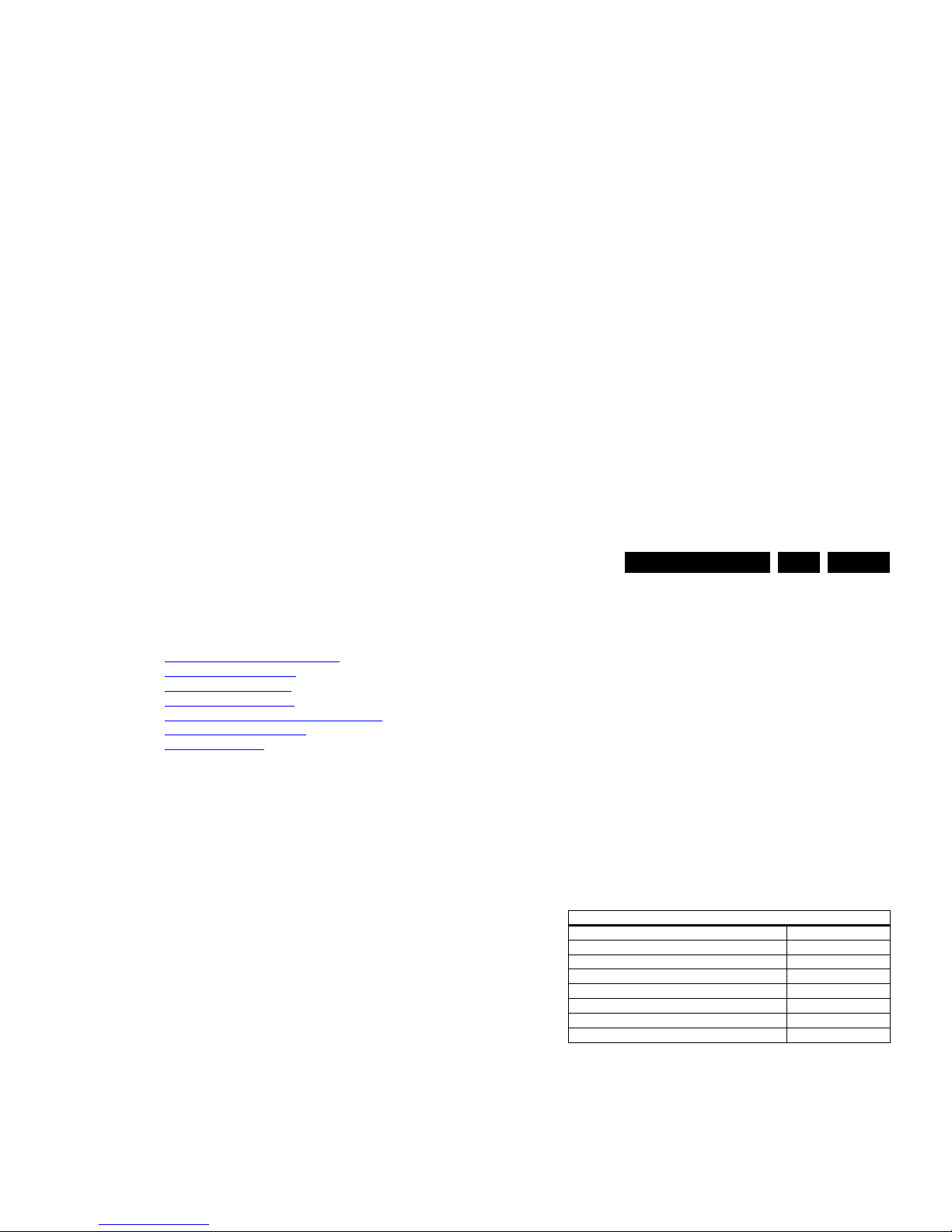
Specifications
Figure 5-3 ComPair II interface connection
Caution: It is compulsory to connect the TV to the PC as
shown in the picture above (with the ComPair interface in
between), as the ComPair interface acts as a level shifter. If
one connects the TV directly to the PC (via UART), ICs will be
blown!
How to Order
ComPair II order codes:
• ComPair II interface: 3122 785 91020.
• ComPair UART interface cable: 3138 188 75051.
• Program software can be downloaded from the Philips
Service web portal.
Note: For this chassis, “Pgammar” and “T-con NVM”
programming (VCOM alignment) are added to ComPair.
Additional cables for VCOM Alignment
10000_036_090121.eps
091118
TO
UART SERVICE
CONNECTOR
TO
UART SERVICE
CONNECTOR
TO
I2C SERVICE
CONNECTOR
TO TV
PC
HDMI
I
2
C only
Optional power
5V DC
ComPair II Developed by Philips Brugge
RC out
RC in
Optional
Switch
Power ModeLink/
Activity
I
2
C
ComPair II
Multi
function
RS232 /UART

Service Modes, Error Codes, and Fault Finding
EN 23L11M1.1L LA 5.
5.4.2 How to Read the Error Buffer
You can read the error buffer in three ways:
• On screen via the SAM/SDM/CSM (if you have a picture).
Example:
– ERROR: 0 0 0 0 0 : No errors detected
– ERROR: 6 0 0 0 0 : Error code 6 is the last and only
detected error
– ERROR: 9 6 0 0 0 : Error code 6 was detected first and
error code 9 is the last detected (newest) error
• Via the blinking LED procedure (when you have no
picture). See paragraph 5.5 The Blinking LED Procedure
.
•Via ComPair.
5.4.3 Error codes
The “layer 1” error codes are pointing to the defective board.
They are triggered by LED blinking when CSM is activated. In
the LC10 platform, only two boards are present: the SSB and
the PSU/IPB, meaning only the following layer 1 errors are
defined:
•2: SSB
• 3: IPB/PSU
•4: Display
Table 5-1 Error code table
5.4.4 How to Clear the Error Buffer
The error code buffer is cleared in the following cases:
Example (2): the content of the error buffer is “12 9 6 0 0”
After entering SDM, the following occurs:
• 1 long blink of 5 seconds to start the sequence,
• 12 short blinks followed by a pause of 1.5 seconds,
• 9 short blinks followed by a pause of 1.5 seconds,
• 6 short blinks followed by a pause of 1.5 seconds,
• 1 long blink of 1.5 seconds to finish the sequence,
• The sequence starts again with 12 short blinks.
5.5.2 Displaying the Entire Error Buffer
Additionally, the entire error buffer is displayed when Service
Mode “SDM” is entered.
5.6 Fault Finding and Repair Tips
Notes:
• It is assumed that the components are mounted correctly
with correct values and no bad solder joints.
• Before any fault finding actions, check if the correct
options are set.
5.6.1 NVM Editor
In some cases, it can be convenient if one directly can change
the NVM contents. This can be done with the “NVM Editor” in
SAM mode. With this option, single bytes can be changed.
Caution:
• Do not change these, without understanding the
function of each setting, because incorrect NVM
settings may seriously hamper the correct functioning
of the TV set!
• Always write down the existing NVM settings, before
changing the settings. This will enable you to return to the
original settings, if the new settings turn out to be incorrect.
5.6.2 Load Default NVM Values
It is possible to download default values automatically into the
Layer-1
error code
Defective
board
Layer-2
error code Defective device
2 SSB 11 Speaker DC protection active on SSB
3 IPB/PSU 16 +12 missing/low, PSU defective
3 IPB/PSU 17 POK line defective
2 SSB 35 EEPROM I2C error on SSB, M24C16
2 SSB 34 Tuner I2C error on SSB
2 SSB 23 HDMI Mux IC I2C error on SSB - Berlinale
models with Mux only
2 SSB 27 Channel decoder on SSB
4Display
(Inverter)
18 LCD Panel inverter error. INV_STATUS
(for 32” sets only)

Service Modes, Error Codes, and Fault Finding
EN 24 L11M1.1L LA5.
5.6.3 No Picture
When you have no picture, first make sure you have entered
the correct display code.
See Display Option Code Selection
for the instructions.
5.6.4 Unstable Picture via HDMI input
Check (via ComPair) if HDMI EDID data is properly
programmed.
5.6.5 No Picture via HDMI input
Check if HDCP key is valid. This can be done in CSM.
5.6.6 HDMI CEC Not Functioning
Go to Home/Menu ->Setup -> Installation -> Preference and
set the Easylink option to “on”. Also check if the connected
device is CEC enabled.
5.6.7 TV Will Not Start-up from Stand-by.
Possible Stand-by Controller failure. Reflash the SW.
5.7 Repair Policy TCON Boards
Thriller sets (xxPFL3x06D/xx) in the 40" range have an
additional “Philips” TCON board (diagram T01). This board
should be swapped separately from the bare LCD panel.
Alignment can be done using ComPair. All other TCON boards
come with the LCD panel and should be swapped together as
one entity.
5.8 Software Upgrading
5.8.1 Introduction
It is possible for the user to upgrade the main software via the
USB port. This allows replacement of a software image in a
2. Execute the command "NVM Copy" > "NVM Copy to USB",
to copy the NVM data to the USB stick. The NVM filename
on the USB stick will be named
"L11M11L_NVM_T2U.BIN" (this takes a couple of
seconds).
Write NVM Data to TV
1. First, ensure (via a PC) that the filename on the USB stick
has the correct format: "L11M11L_NVM_U2T.BIN".
2. Insert the USB stick into the USB slot while in SAM mode.
3. Execute the command "NVM Copy" > "NVM Copy from
USB" to copy the USB data to NVM (this takes about a
minute to complete).
To write an NVM mask to the TV, ensure that the mask has the
correct format: "L11M11L_NVM_U2T.MAK" (0x00 to write
protect, 0xFF to overwrite).
Important: The file must be located in the "/Repair" directory
of the USB stick.
5.8.4 How to Copy EDID Data to/from USB
Write EDID Data to USB
1. Insert the USB stick into the USB slot while in SAM mode.
2. Execute the command "NVM Copy" > "EDID Copy to
USB", to copy the EDID data to the USB stick. The
filename on the USB stick will be named
"L11M11L_EDID_T2U.BIN" (this takes a couple of
seconds).
Write EDID Data to TV
1. First, ensure (via a PC) that the filename on the USB stick
has the correct format: "L11M11L_EDID_U2T.BIN".
2. Insert the USB stick into the USB slot while in SAM mode.
3. Execute the command "NVM Copy" > "EDID Copy from
USB" to copy the USB data to EDID (this takes about a
minute to complete).
Important: The file must be located in the "/Repair" directory
of the USB stick.
5.8.5 How to Copy the Channel List to/from USB
Alignments
EN 25L11M1.1L LA 6.
6. Alignments
Index of this chapter:
6.1 General Alignment Conditions
6.2 Hardware Alignments
6.3 Software Alignments
6.4 ADC gain adjustment
6.5 TCON Alignment (= VCOM alignment)
6.6 Additional TCON Board
6.7 Option Settings
Note: Figures below can deviate slightly from the actual
situation, due to the different set executions.
General: The Service Default Mode (SDM) and Service
Alignment Mode (SAM) are described in chapter 5. Menu
navigation is done with the CURSOR UP, DOWN, LEFT or
RIGHT keys of the remote control transmitter.
6.1 General Alignment Conditions
Perform all electrical adjustments under the following
conditions:
• Power supply voltage (depends on region):
– AP-NTSC: 120 V
AC
or 230 VAC / 50 Hz ( 10%).
– AP-PAL-multi: 120 - 230 V
AC
/ 50 Hz ( 10%).
– EU: 230 V
AC
/ 50 Hz ( 10%).
– LATAM-NTSC: 120 - 230 V
AC
/ 50 Hz ( 10%).
– US: 120 V
AC
/ 60 Hz ( 10%).
• Connect the set to the mains via an isolation transformer
with low internal resistance.
• Allow the set to warm up for approximately 15 minutes.
• Measure voltages and waveforms in relation to correct
ground (e.g. measure audio signals in relation to
AUDIO_GND).
Caution: It is not allowed to use heatsinks as ground.
• Test probe: Ri > 10 Mohm, Ci < 20 pF.
• Use an isolated trimmer/screwdriver to perform
alignments.
6.2 Hardware Alignments
6.3 Software Alignments
With the software alignments of the Service Alignment Mode
(SAM) the Tuner and RGB settings can be aligned.
6.3.1 Tuner Adjustment (RF AGC Take Over Point)
Purpose: To keep the tuner output signal constant as the input
signal amplitude varies.
No alignment is necessary, as the AGC alignment is done
automatically.
6.3.2 RGB Alignment
Before alignment, set the picture as follows:
White Tone Alignment:
• Activate SAM.
• Select “RGB Align.“ and choose a color temperature.
• Use a 100% white screen as input signal and set the
following values:
– “Red BL Offset” and “Green BL Offset” to “7” (if
present).
– All “White point” values initial to “127”.
In case you have a color analyzer:
• Measure with a calibrated (phosphor- independent) color
analyzer (e.g. Minolta CA-210) in the centre of the screen.
Picture Setting
Dynamic backlight Off
Dynamic Contrast Off
Color Enhancement Off
Picture Format Unscaled
Light Sensor Off
Brightness 50
Color 0
Contrast 100
Alignments
EN 26 L11M1.1L LA6.
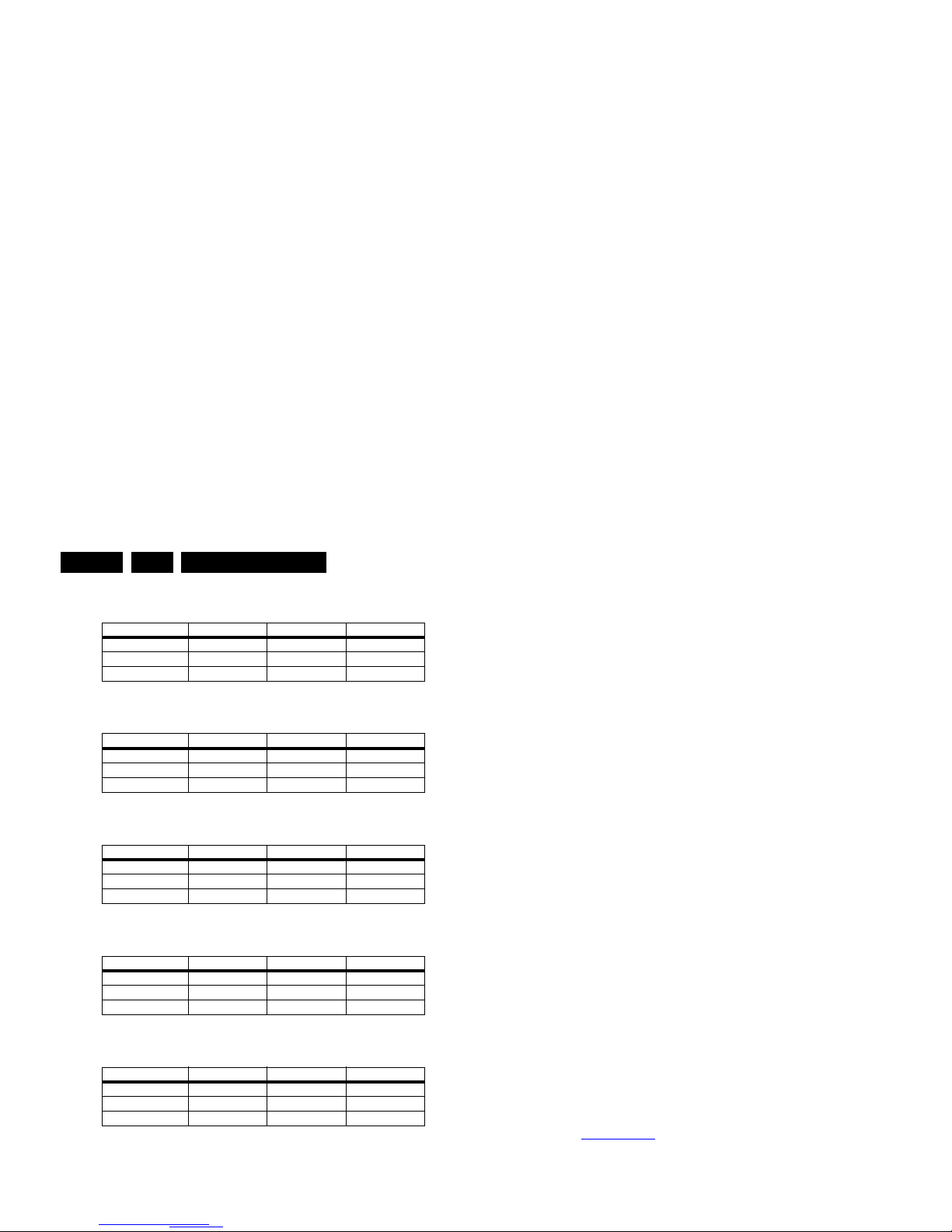
Table 6-2 Tint settings 32" Thriller HD (xxPFL3406D/xx)
Table 6-3 Tint settings 32" Thriller FHD (xxPFL3606D/xx)
Table 6-4 Tint settings 40" Thriller FHD (xxPFL3606D/xx)
Table 6-5 Tint settings 32" Berlinale FHD (xxPFL5606D/xx)
Table 6-6 Tint settings 40" Berlinale FHD (xxPFL5606D/xx)
6.4 ADC gain adjustment
Use a Quantum Data Patters Generator 802BT and apply a
“PgcWrgb” image (“dot, cross and color bar mix pattern”)
according to Figure 6-1
.
• Select the input source to YPbPr input.
• In SAM, initiate the “Auto ADC” calibration command.
Upon appearance of the “Auto ADC Completed” message, the
alignment is completed.
Notes:
1. Peak-to-Peak
2. Black-to-Peak.
6.4.2 PC VGA
Following instructions result in correct alignment of ADC gain,
offset and phase, related to PC VGA input signal. Apply a
signal of format “DMT1060”.
• Apply following signals to the PC VGA input connector:
– Red signal of 0.7 Vp-p
1
/ 75 ohm.
– Green signal of 0.7 Vp-p
1
/ 75 ohm.
– Blue signal of 0.7 Vp-p
1
/ 75 ohm.
• Select the input source to PC VGA input.
• In SAM, initiate the “Auto ADC” calibration command.
Upon appearance of the “Auto ADC Completed” message, the
alignment is completed.
6.5 TCON Alignment (= VCOM alignment)
New requirement for “TCON on SSB” project:
• The purpose of VCOM alignment is to obtain an equal
voltages for both Positive and Negative LC polarity. This is
important to avoid “Flicker” and “Image Sticking”.
• The P-Gamma + VCOM calibrator IC, ISL24837 is used for
VCOM adjustment.
• The adjusted VCOM data will be stored inside on-chip
memory and will be automatically recalled during each
power-up.
ComPair (see 5.3.1 ComPair
) will foresee in a possibility to do
this alignment.
6.6 Additional TCON Board
Thriller sets (xxPFL3x06D/xx) in the 40" range have an
Colour Temp. R G B
Cool 201 240 255
Normal 2 27 255 243
Warm 243 249 164
Colour Temp. R G B
Cool 246 246 248
Normal 2 42 240 246
Warm 255 231 155
Colour Temp. R G B
Cool 212 244 254
Normal 2 31 255 236
Warm 242 252 161
Colour Temp. R G B
Cool 187 255 241
Normal 2 11 254 217
Warm 234 254 156
Colour Temp. R G B
Cool t.b.d. t.b.d. t.b.d.
Normal t.b.d. t.b.d. t.b.d.
Warm t.b.d. t.b.d. t.b.d.

Alignments
EN 27L11M1.1L LA 6.
How to Change Options Codes
An option code (or “option byte”) represents eight different
options (bits). All options are controlled via ten option bytes
(OP#1... OP#10).
Activate SAM and select “Options”. Now you can select the
option byte (OP#1... OP#10) with the CURSOR UP/ DOWN
keys, and enter the new 3 digit (decimal) value. For the correct
factory default settings, see the sticker inside the set.
Circuit Descriptions
EN 28 L11M1.1L LA7.
7. Circuit Descriptions
Index of this chapter:
7.1 Introduction
7.2 Power Supply
7.3 Video
7.3.1 Video: Front-End
7.4 Audio
7.5 Inputs
7.5.1 Inputs: HDMI
7.5.2 Inputs: USB
Notes:
•Only new circuits (circuits that are not published recently)
are described.
• Figures can deviate slightly from the actual situation, due
to different set executions.
• For a good understanding of the following circuit
descriptions, please use chapter 9. Block Diagrams
and
10. Circuit Diagrams and PWB Layouts
. Where necessary,
you will find a separate drawing for clarification.
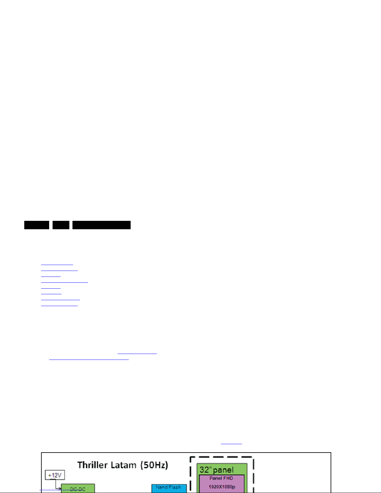
7.1 Introduction
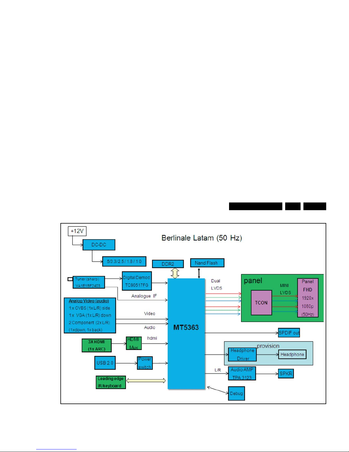
The LC11M1.1L LA chassis is a digital chassis using a
Mediatek chipset. It covers screen sizes of 32" to 40".
The xxPFL3x06D/xx sets come with the “Thriller” styling, and
the xxPFL5x06D/xx come with the “Berlinale” styling.
Main key components are the Mediatek MT5363 integrated
“System On Chip” (SoC) that supports multimedia video/audio
input, and the integrated TCON (Timing Controller), part for the
LCD panel. Thriller sets (xxPFL3x06D/xx) in the 40" range
however have an additional “Philips” TCON board (diagram
T01) that comes separate from the LCD panel and that should
be swapped separately.
System SoC is based on MT5363:
• NAND Flash – 128 Mbyte, NumOnyx/Hynix.
• DDR – 128 Mbyte (32 × 16M, 2 pcs), Hynix.
• Use internal MT5363 Stand-by micro-controller.
Tuner/Frontend configuration:
• Half NIM tuner (VA1E1BF2403) from Sharp.
• Toshiba Channel Decoder (TC90517).
Interfaces for debug and SW upgrade:
• UART (3.5 mm jack).
• USB port.
•JTAG.
Refer to Figure 7-1
for details.
Circuit Descriptions
EN 29L11M1.1L LA 7.
Figure 7-2 L11M1.1L LA Architecture Berlinale (xxPFL5x06D/xx)
19131_022_110623.eps
110623
Circuit Descriptions
EN 30 L11M1.1L LA7.
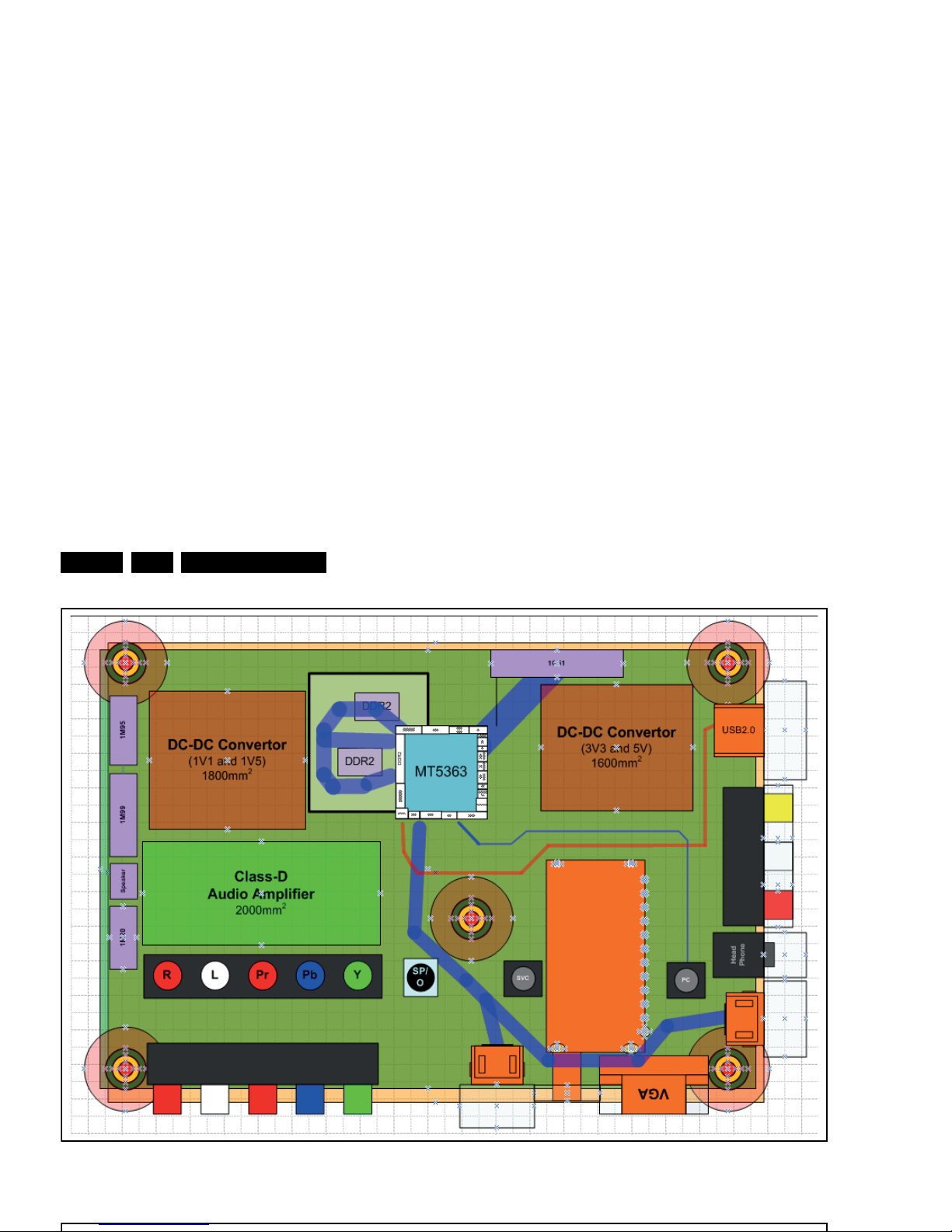
Figure 7-3 SSB cell layout Thriller (xxPFL3x06D/xx)
19130_010_110426.eps
110426
 Loading...