

Philips 40PFL1708/F7 Owner’s Manual
Register your product and get support at
WWWopsilipSoCOm/support
50PFL3708
46PFL3708
40PFL4708
40PFL1708
39PFL2708
32PFL3508
32PFL4508
29PFL4508
24PFL4508
EN User Manual
ES Manual del Usuario
FR Manuel d'Utilisation
EN
For further assistance, call the customer support service in your country.
To obtain assistance, contact Ph[l[ps Customer Care Center;
In the U.S.A., Canada, Puerto Rico, orthe U.S. Vir£[n Islands 1 866 309 5962
M6x[co D.F. and Area Metropolitana; 58 87 97 36
Interior de la Republ[ca; 01 800 839 19 89
E$
Para obtener m_s informaci6n, Ilame al servicio de soporte al cliente de su pal's.
Para obtener as[stenda, comun[quese con Centro de atenciGn aEd[ente de Ph[l[ps;
En Eos Estados Unidos, en Canada, Puerto Rico o en las Bias V[rgenes de los
Estados Un[dos; 1 866 309 5962
M6x[co D.F. 7 Area Metropol[tana; 58 87 97 36
Interior de la Republ[ca; 01 800 839 19 89
FR
Pour obtenir de I'aide suppl_mentaire, communiquez avec le centre de service
la clientele de votre pays.
Pour- obtenir de I'a[de, commun[quez avec le centre de service £ la cl[ent61e PNl[ps au;
Dans le Etats Unis, au Canada, £ Puerto Rico ou aux TiesVierges am@-icaines; 1 866 309 5962
M6x[co D.F. et _,ma Metropol[t_sna; 58 87 97 36
Interior de la Republ[ca; 01 800 839 19 89

Contents
1 Notice s
2 Important
Positioning the TV
Regulatory notices
Environmental care
Get staked
Features 7
Supplied accessories 7
Symbols used in this User Manual 7
Stand assembly 8
Attaching the base 8
Managing cables 9
Installingthe remote control batteries 9
Remote control I 0
Control panel 1I
Terminals 11
Connecting the antenna or the cabte I2_
Connecting a set-top box, Blu-ray disc / DVD recorder via
composite connectors and Analog Audio I2_
Plugging in the AC power cord I 2
Selecting your connection quality I3
HDNI - Highest quality I3
Component (Y Pb Pr) - High quality I3
Composite - Basic quality I3
Connecting your devices 13
HDNI Digital connection I3
HDNI-DVI connection 13
Component Analog Video Connection I4
Composite Analog Video Connection I4
Digital Audio Output Connection I4
PC connection I5
USB Memory Stick I5
Initial setup I6
4
Use your TV
Switching on your TV and putting it in Standby mode
Adjusting volume
Switching channels
Watching channels from an external device
Sleep timer
Switching audio mode
EasyLinl<options
Changing picture format
TV screen information
I8
I8
I8
I8
I9
I9
I9
20
20
2I
Use more of your TV
Displaying the Main Menu
6
6
6
6
7
Picture
Sound
Setup
Autoprogram
Channet list
Add channels
Antenna confirmation
Features
Caption settings
Child and ratings lock
Channel loci<
Setting US movie and TV ratings
Canadian English or Canadian French ratings
Change PIN
PC settings
EasyLinl<(HDNI CEC)
Device list
Setting your location to home
E-sticker
Language
USB
Picture (JPEG)
Video (Motion JPEG)
6
Upgrade your TV software
Checking your current software version
Upgrading the software
7
Useful tips 34
FAQ 34
Troubleshooting 35
8
Information 36
Glossary 36
Maintenance 36
22
2_2_
23
24
24
2_4
25
25
25
26
2_6
2_7
2_7
28
2_9
2_9
2_9
30
30
31
3t
31
32
32_
32_
33
33
33
9 Specifications 37
10 Warranty 38

Registering your model with Philips makes you eligible for all of the valuable benefits listed below, so don't miss out.
Register online at www.productrecords.comlphl to ensure:
i!iii! iiil@ ii¸
Know these sQfe_ symbols
RISKOF ELECTRICSHOCK
DO NOT OPEN
CAUTION:TO REDUCETHERISKOFELECTRICSHOCK,DONOT
REMOVECOVER(ORBACK).NOUSER-SERVICEABLEPARTS
INSIDE.REFERSERVICINGTOQUALIFIEDSERVICEPERSONNEL.
Thecautionmarkingislocatedon therearor bottomof thecabinet.
WARNING:
CAUTION:
ATTENTION:
To reduce the risk of fire or electric shock, do not expose this apparatus to rain or moisture. Apparatus shall
not be exposed to dripping or splashing and no objects filled with liquids, such as vases, shall be placed on the
apparatus.
To prevent electric shock, match wide blade of plug to wide slot, fully insert.
Pour _viter les choc _lectriques,introduire la lame la plus large de la fiche dans la borne correspondante de la
prise et pousser jusqu'au fond.
CHILD SAFETY:
PROPER TELEVISION PLACEHENT HATTERS
THE CONSUMER ELECTRONICS INDUSTRY
CARES
• Manufacturers, retailers and the rest of the consumer
electronics industry are committed to making home
entertainment safe and enjoyable.
• As you enjoy your"television, please note that all televisions -
new and old- must be supported on proper stands or" installed
according to the manufacturer's recommendations. Televisions
that are inappropriately situated on dressers, bookcases,
shelves, desks, speakers, chests, carts, etc., may fall over',
resulting in injury.
TUNE IN TO SAFETY
• ALWAYS follow the manufacturer's recommendations for"the
safe installation of your television.
• ALWAYS read and follow all instructionsfor" proper use of
your"television.
• NEVER allow children to climb on or" play on the television or"
the furniture on which the television is placed.
• NEVER place the television on furniture that can easily be used
as steps, such as a chest of drawers.
• ALWAYS install the television where it cannot be pushed,
pulled over" or" knocked down.
• ALWAYS route cords and cables connected to the television
so that they cannot be tripped over', pulled or"grabbed.
C E.org/safety
Cons_me_ El_t tunics Associati_
The lightning flash with arrowhead symbol, within an equilateral
triangle, is intended to alert the user to the presence of
uninsulated "dangerous voltage" within the apparatus's enclosure
A
that may be of sufficient magnitude to constitute a risk of
electric shock to persons.
The exclamation point within an equilateral triangle is intended to
_ alert the user to the presence of important operating and
maintenance (servicing) instructions in the literature accompanying
the apparatus.
WALL OR CEILING MOUNT YOUR TELEVISION
• ALWAYS contact your retailer about professional installation if
you have any doubts about your" ability to safely mount your"
television.
• ALWAYS use a mount that has been recommended by the
television manufacturer and has a safety certification by an
independent laboratory (such as UL, CSA, ETL).
• ALWAYS follow all instructions supplied by the television and
mount manufacturers.
• ALWAYS make sure that the wall or"ceiling where you are
mounting the television is appropriate. Some mounts are not
designed to be mounted to walls and ceilings with steel studs
or" cinder" block construction. If you are unsure, contact a
professional installer'.
• Televisions can be heavy. A minimum of two people is
required for" a wall or" ceiling mount installation.
MOVING AN OLDER TELEVISION TO A NEW
PLACE IN YOUR HOME
• Many new television buyers move their" older" CRT televisions
into a secondary room after"the purchase of a flat-panel
television. Special care should be made in the placement of
older" CRT televisions.
• ALWAYS place your" older" CRT television on furniture that is
sturdy and appropriate for" its size and weight.
• NEVER place your" older" CRT television on a dresser where
children may be tempted to use the drawers to climb.
• ALWAYS make sure your" older" CRT television does not hang
over"the edge of your" furniture.

Important Safety Instructions
i!ii! ii ¸
1. Read these instructions,
2. Keep these instructions,
3. Heed all warnings
4. Follow all instructions
5. Do not use this apparatus nearwatel:
6, Clean onl7 with dry cloth
7. Do not block an7 ventilation openings Install in accordance with the
manufacturer's instructions
8. Do not install near any heat sources such as radiators, heat registers,
stoves, or other apparatus (including amplifiers) that produce heat.
9. Do not defeat the safety purpose of the polarized or grounding-
type plug. A polarized plug has two blades with one wider than the
othel:A grounding type plug has two blades and a third grounding
prong.The wide blade or the third prong are provided for your
safety.If the provided plug does not fit into your outlet, consult an
electrician for replacement of the obsolete outlet.
10. Protect the power cord fi-om being walked on or pinched
particularl 7 at plugs, convenience receptacles, and the point where
the 7 exit from the apparatus.
11. Onl 7 use attachments / accessories specified b7the manufacturel:
12. Use onl 7 with the cart, stand, tripod, bracket or table
specified by the manufacturer, or sold with the
apparatus.When a cart is used, use caution when
moving the cart / apparatus combination to avoid injury
fi-om tip-ovel:
13. Unplug this apparatus during lightning storms or when unused for
long periods of time
14. Refer all servicing to qualified service personnel. Servicing is
required when the apparatus has been damaged in any way, such
as powel_suppl7 cord or plug is damaged, liquid has been spilled
or objects have fallen into the apparatus, the apparatus has been
exposed to rain or moisture, does not operate normally, or has
been dropped.
Note to the CATV system installer:
This reminder is provided to call the CATV system installeCs
attention to Article 820-40 of the NEC that provides guidelines for
proper grounding and, in particulac specifies that the cable ground
shall be connected to the grounding system of the building, as close
to the point of cable entry as practical.
Example of Antenna Grounding as per NEC - National
Electric Code
GROUND CLA-MP_ ANTENNA LEAD INWlRE
___. ANTENNA DISCHARGE
2 Z'22; ,T2'c°;Z°S
Wall Mount Bracket Kit
Brand
50PFL3708 /
46PFL3708
40PFL4708 /
39PFL2708
40PFL1708 SANUS
32PFL3508 /
32PFL4508 / SANUS
29PFL4508
24PFL4508 SANUS
The recommended Wall Mount Bracl<et Kit (sold separately)
allows the mounting of theTV on the wall.
. For detailed information on installing the wall mount, refer to the
Wall Mount Instruction Book
. P&F USA is not responsible for any damage to the product or
injury to yourself or others if you elect to install the TV Wall
Mount Bracket or mount theTV onto the Bracl<et on your own.
. The Wall Mount Bracl<et must be installed by experts.
PHILIPS
PHILIPS
Model #
SQH6485
SQH6435/17
SAN25BB
SAN18B
MST15
Screw dimension
M6 x 1.614" (41ram)
with spacer
M6 x 1.614" (41ram)
with spacer
M4 x 0.472" (12ram)
M4 x 0.472" (12ram)
M4 x 0.472" (12ram)
ELECTRIC SERVICE T...._..._ POWER SERVICEGROUNDING
EQUIPMENT ELECTRODE SYSTEM
P&F USA is not liable for these types of accidents or injury noted
below.
. Install the Wall Mount Bracket on a sturdy vertical wall.
. If installed onto a ceiling or slanted wall, the TV and Wall Mount
Bracket may fall which could result in a severe injury.
. Do not use screws that are longer or shorter than their specified
length. If screws too long are used this may cause mechanical or
electrical damage inside theTV set. If screws too short are used
this may cause theTV set to fall.
. Do not fasten the screws by excessive force.This may damage
the product or cause the product to fall, leading to an injury.
. For safety reasons use 2 people to mount theTV onto aWali
Mounting Bracl<et
. Do not mount theTV onto the Wall Mounting Bracl<et while
7ourTV is plugged in orTurned On. It may result in an electrical
shock injury.
When installing the unit on the wall, allow this much space.
Top: 11.8 inches (30cm)
Left and right side: 5.9 inches (1Scm)
Bottom: 3.9 inches (10cm)
(NEC ART 250,PARTH)
@!,li!iil@ i i iii¸
1 Notice
Trademarks are the property of Koninldijke Philips NM or their
respective owners
P&F USA reserves the right to change products at any time without
being obliged to adju£ earlier supplies accordingly.
The material in this manual is believed adequate for the intended use of
the sy£em If the product or its individual modules or procedures are
used for purposes other than those specified herein, confirmation of
their validity and suitability mug be obtained P&F USA warrants that
the material itself does not infifinge any United States patents No
further warranty is expressed or implied
P&F USA cannot be held responsible neither for any errors in the
content of this document nor for any problems as a result of the
content in this document Errors reported to P&F USA will be adapted
and published on the P&F USA support website as soon as possible
Pixel characteristics
This LCD product has a high number of color pixels.Although it has
effective pixels of 99.999% or more, black dots or bright points of light
(red, green or blue) may appear con£antly on the screen This is a
£ructural property of the display (within common indu£ry £andards)
and is not a real@notion
Warranty
No components are user serviceable. Do not open or remove covers
to the inside of the product Repairs may only be done by Service
Centers and official repair shops. Failure to do so shall void any
warranty, stated or implied
Any operation expressly prohibited in this manual, any adjustments or
assembly procedures not recommended or authorized in this manual
shall void the warranty.
Federal Communications Commission Notice
This equipment has been tested and found to comply with the limits
for a Class B Digital device, pursuant to part 15 of the FCC Rules.
These limits are designed to provide reasonable protection against
harmful interference in a residential installation.This equipment
generates, uses and can radiate radio frequency energy and, if not
installed and used in accordance with the instructions, may cause
harmful interference to radio communications. However, there is no
guarantee that interference will not occur in a particular installation. If
this equipment does cause harmful interference to radio or television
reception, which can be determined by turning the equipment off and
on, the user is encouraged to try to correct the interference by one
or more of the following measures:
. Reorient or relocate the receiving antenna
, Increase the separation between the equipment and the receivel:
, Connect the equipment into an outlet on a circuit different fi-om
that to which the receiver is connected
, Consult the dealer or an experienced radio or television technician
for help
Declaration of Conformity
Trade Name :
Responsible Party :
Model:
Address: PC Box 2_2`48,Alpharetta, GA 3002_3-2_2_48
Telephone Number : 1 866 309 5962_
PHILIPS
P&F USA, Inc.
50PFL3708, _6PFL3708, _0PFL4708,
40PFL1708, 39PFL2708, 32PFL3508,
32PFL4508, 29PFL4508, 24PFL4508
USA
Modifications
This apparatus may generate or use radio frequency energy. Changes
or modifications to this apparatus may cause harmful interference
unless the modifications are expressly approved in the User Manual
The user could lose the authority to operate this apparatus if an
unauthorized change or modification is made
Cables
Connections to this device must be made with shielded cables with
metallic RFI / EMI connector hoods to maintain comp%nce with FCC
Rules and Regulations
Canadian notice
CAN ICES-3 (B)/NHB-3 (B)
Standard Television ReceivingApparatus, Canada BETS-7 / NTHR-7.
Copyright
All other registered and unregistered trademarl<s are the property of
their respective owners
The terms HDN1 and HDMI High-Definition
HI ITIIll °
HI_-DEFI_ITlaNMU_IM_IAI_TERFAaE
[_ DOLBY
DiGiTAL
SfS_ TruSurround XT technology is incorporatedunder license from SRS Labs, Inc.
TruSurroundXT SRSTruSurround XT ® creates a truly immersive
÷ SRSTruSurround XT technolog 7 is supported in 40PFL4708,
39PFL2_708,32_PFL3S08, 32_PFL4508,2_9PFL4508, 2_4PFL4508 only.
Consumer Notice:
ThisTV has been set to maximize energy efficiency while delivering the
best possible picture using the factory installed home mode settings.
Changing or enabling other features in thisTV (e.g. brightened
backlighting) will possibly increase energy consumption beyond the
original ENERGY STAR® qualified limits.
Nultimedia Interface, and the HDNI Logo are
trademarks or registered trademarks of HDNI
Licensing LLC in the United States and other
countries
Manufactured under license fi-om Dolby
Laboratories. Dolby and the double-D symbol
are trademarl<s of Dolby Laboratories
S[S_ is a trademark of SRS Labs,Inc.
surround sound experience with rich bass and
clear dialog from only two speal<ers.
ENERGY STAR® is a joint program of the U.S.
Environmental Protection Agency and the U.S.
Department of Energy helping us all save
money and protect the environment through
energy efficient products and practices.
LED bacldightingtechnology useslessenergy
when compared with a standard CCFL
bacldightingLCD television of the same
screensizeActual energy savingswill vary
dependingon the screensize
Portions of this software are copyright @The FreeType Project
(www.freetype.org).
The American Academy of Pediatrics discourages television viewing
for children younger than two years of age.
i!iii! !ii!i@ i i iii¸
2 Important
Positioning the TV
e
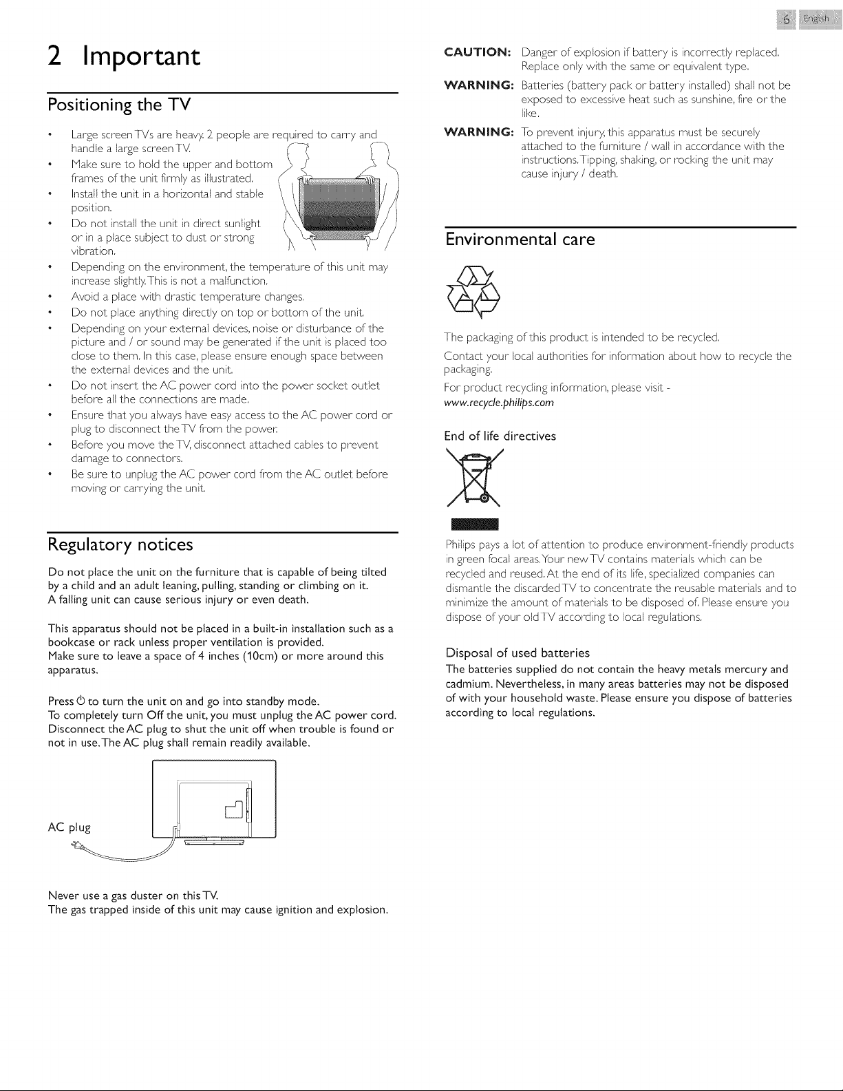
Large screen TVs are heavy. 2_people are required to carry and
handle a large screenT_4
e
Make sure to hold the upper and bottom
frames of the unit firmly as illustrated.
e
Install the unit in a horizontal and stable
position.
e
Do not install the unit in direct sunlight
or in a place subject to dust or strong
vibration
Depending on the environment, the temperature of this unit may
increase slightly.This is not a malfunction
e
Avoid a place with drastic temperature changes
e
Do not place anything directly on top or bottom of the unit
e
Depending on your external devices, noise or disturbance of the
picture and / or sound may be generated if the unit is placed too
dose to them In this case, please ensure enough space between
the external devices and the unit
e
Do not insert the AC power cord into the power socket outlet
before all the connections are made
e
Ensure that you always have easy access to the AC power cord or
plug to disconnect theTV from the power.
e
Before you move theTV, disconnect attached cables to prevent
damage to connectors
e
Be sure to unplug the AC power cord fi-om the AC outlet before
moving or carrying the unit
CAUTION:
Danger of explosion if battery is incorrectly replaced
Replace only with the same or equivalent type
WARNING:
Batteries (battery pack or battery installed) shall not be
exposed to excessive heat such as sunshine, fire orthe
like
WARNING:
To prevent injury, this apparatus must be securely
attached to the fiJrniture / wall in accordance with the
instructions Tipping, shaking, or rocking the unit may
cause injury / death
Environmental care
The packaging of this product is intended to be recycled
Contact your local authorities for information about how to recycle the
packaging
For product recycling information, please visit -
www, recyde,pflilips,com
End of life directives
Regulatory notices
Do not place the unit on the furniture that is capable of being tilted
by a child and an adult leaning, pulling, standing or climbing on it.
A falling unit can cause serious injury or even death.
This apparatus should not be placed in a built-in installation such as a
bookcase or rack unless proper ventilation is provided.
Make sure to leave a space of 4 inches (10cm) or more around this
apparatus.
Press (_ to turn the unit on and go into standby mode.
To completely turn Offthe unit, you must unplug theAC power cord.
Disconnect theAC plug to shut the unit off when trouble is found or
not in use.TheAC plug shall remain readily available.
plug _ "
Never use a gas duster on thisTV.
The gas trapped inside of this unit may cause ignition and explosion.
Philips pays a Jot of attention to produce environment-friendly products
in green focal areas.Your newTV contains materials which can be
recycled and reused.At the end of its life, specialized companies can
dismantle the discarded TV to concentrate the reusable materials and to
minimize the amount of materials to be disposed of. Please ensure you
dispose of your old TV according to local regulations.
Disposal of used batteries
The batteries supplied do not contain the heavy metals mercury and
cadmium. Nevertheless, in many areas batteries may not be disposed
of with your household waste. Please ensure you dispose of batteries
according to local regulations.

i!iil; iii/@ i i iii¸
3 Get started
Featu res
• DTV / Analog TV / CATV
You can use your remote control to select channels whici7 are broadcast in Digital
formal and conventional Analog forma±. Also, cable subscribers can access their cable
]V channels,
• Information display
You can display the title, contents (DTV only) and other information of the current
program on the TV screen,
• Autoprogram
Ihis unit automatically scans and memorizes channels available in your area, eliminating
difficult setup procedures.
• Child lock
Ihis feature allows you to block children's access to inappropriate programs.
• Closed Caption decoder
Built in Closed Caption decoder displays text for Closed Cap_ion supported programs.
• MTS / SAP tuner
Audio can be selected fi-om the remote control
• Auto Standby
If there is no Input signal and no operation for I 5 minutes, the unit will go into Standby
mode automatically.
• Sleep timer
You carl se_ the unit to go into Standby mode after a specific amount of time.
• Choices for on-screen language
Selec_ your on screen language: English, Spanish or French.
• Stereo sound function
• PLL frequency synthesized tuning
Provides free and easy channel selection and lets you tune directly to any channel using
the number and decimal point "•" buttons on the remote control.
• Various adjustment for picture and sound
Customizes image quality suitable for your room and sets your sound preference,
• EasyLink via HDMI link
EasyLink allows your other- HDMI link devices to be controlled by the HDNI cable
connected to your IV.
• HDMI Input
• HDMI-DVI Input
If your video device has DVI Output jack, use an HDMI DVI conversion cable to
connect the unit.
• Component Video Input
• PC Input
• AV Input
• USB terminal
]he picture (]PEG) and video (Motion jPEG) files stored on a USB Memory Stick can
be played back on this unit.
• Digital Audio Output
• Headphone Audio Output
Supplied accessories
User Manual
Remote Control and
batteries
(AAA, 1.5V x 2)
O
ca c_
C3C3CD
C3CDCD
C3C73CD
C3C3CD
Quick Start guide
TV base and screws
DoO
C3C23C3
Screws packed with this unit.
Model Quantity Size
50PFL3708/
46PFL3708
40PFL4708/ 3
39PFL2708 4
40PFL1708 3
32PFL3508/
32PFL4508/
29PFL4508/
24PFL4508
Note
• If you lose the screws, please purchase the above-mentioned Phillips head screws at
your local store.
• If you need to replace these accessories, pMase ref:sr to dqe part name or No. with the
illustrations and call our toll fi-ee customer support line found on the cover of this User
Manual.
When using a universal remote control to operate ths uniL
• Make sure the component code on your universal remote control is set to our brand.
Refer to the instruction book accompanying your remote control for more details,
• We do not guarantee 100% interoperability with all universal remote controB,
8
3
H4 x 0.472"(12ram)
H4 x 0.393"(10mm)
H4 x 0.787"(20mm)
H4 x 0.787"(20mm)
H4 x 0.984"(25mm)
Symbols used in this User Manual
The following is the description for the symbols used in this User
Manual. Description refers to:
• If neither symbol appears, the operation is applicable to both.
i!ii!_!l@_i_i_iii¸
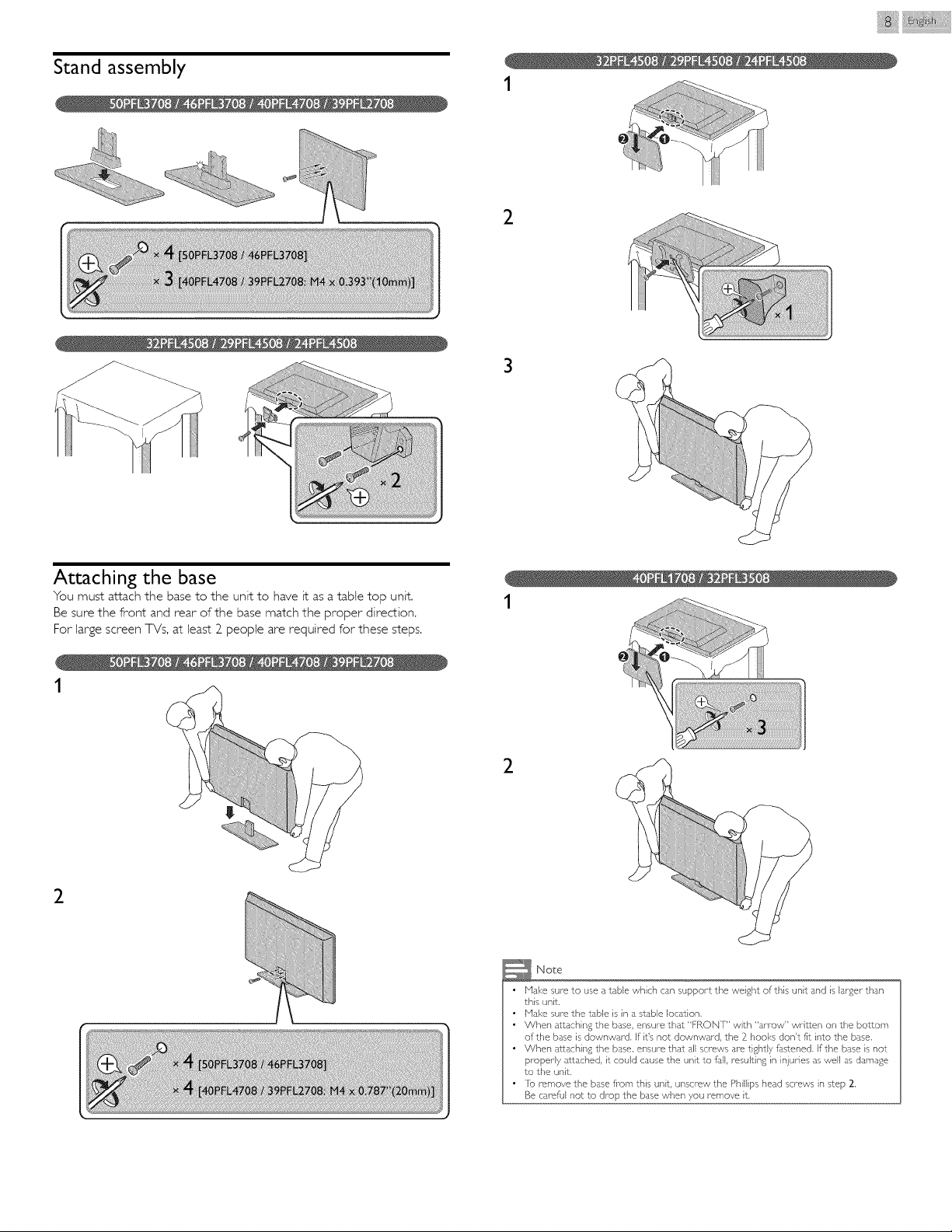
Stand assembly
1
2
3
Attaching the base
You must attach the base to the unit to have it as a table top unit,
Be sure the front and rear of the base match the proper direction,
For large screen TVs, at least 2 people are required for these steps.
1
2
1
2
Note
• Make sure to use a table which can support the weight of this unit and is lar£er than
this unit,
• Mal<e sure the table is in a stable location,
• When attaching the base, ensure that "FRON] " with "arrow" written on the bottom
of the base is downward. If it's not downward, the 2 hooks don't fit into the base.
• When a_aching the base, ensure that all screws are tightly fdsSened. If the base is not
properly attached, it could cause the unit to full, resulting in injuries as well as damage
to the unit.
• Io remove the base fi_om this unit unscrew the Phillips head screws in step 2.
Be careful not to drop the base when you remove it.

Managing cables
Route your antenna cable and all other cables through the cable
management tie* at the back of the TV.
The holder helps keep your cables tidy and easily manageable.
1 Attach the cable management tie as illustrated below.
_- Pass cables through the cable management tie to avoid tangles.
f"
i!ii li ¸
* The cable management tie is not supplied with your TV, If you would
like this part, please call our toll free customer support line found on
the cover of this User Manual, and it will be sent to you for free of
charge.
Installing the remote control batteries
1 Slide the battery cover offthe back of the remote control.
_- Insert the 2 supplied batteries (AAA, 1.5V). Be sure the + and -
ends of the batteries line up with the markings inside the case.
3 Slide the cover back into position.
_e N°bs
move the batteries if not using the remote control for an extended period of time, ]

iii_}}i_l_@__i_i_iii¸
Remote control
0 (POWER)
Turns the TV On from Standby or Offto Standby,
EasyLink(HDMI CEC) buttons
• Begins or Restarts the Disc playback,
IIII Pauses the Disc playback,
• Stops the Disc playback,
/ _ Searches Backward or Forward through the disc,
,No_e
u must set On in the Master EasyLink (" p.30) to operate the above
notions,
SAP
®
Selects Audio mode (MONO/STEREO/SAP) / Audio lan£ua£e,
®
1_ (MENU)
Displaysthe main menu.
INFO []_]
®
Displays Information about the current program.
®
• • _11_ (NAVIGATION buttons) / OK
Moves the cursor, Selects the On-screen Menu items.
@
[_ OPTIONS
Opens EasyLinl<options menu.
u must set On in the Master EasyLink (" p.30) to operate the above
nctions.
®
®
@
@
SOURCE
Selects Connected devices.
CH+I-
Selects a Channel.
COLOR buttons
Use these Buttons according to the directions On-screen,
0 - 9 (NUMBER buttons)
Used to enter a Channel / Program number.
• (DOT) Use with 0-9 to select digital channels. For example, to
enter Z1, press
PREV.CH Returns to the previously viewed Channel.
(_ '_x (MUTE)
Turns the Sound On and Off,
(_) VOL + / -
Adjusts the Volume.
(_) BACK
Returns to the previous Menu operation.
(_) FORMAT
Adjusts the Picture size on the TV screen.
(_) SLEEP
Sets Sleep Timer.
(_) cc
Displays the audio portion of programming as text superimposed
over the video,

iii }}i iii ¸
Control panel
Terminals
®
©
VOL _III_
Adjusts the Volume. In the Menu screen, moves the Cursor Left
(_1) / Right (1_).
VOL _1 : Volume Down
VOL I_ : Volume Up
CH &IT
®
Selects a Channel. In the Menu screen, moves the Cursor Up (&)
/Down (V).
MENU
®
Opens the Main On-screen Menu.
SOURCE
®
Selects Connected devices.
®
®
®
(POWER)
Turns the TV On and Off.
Remote Control Sensor
Receives IR signal from Remote control,
Power On / Standby Indicator
(On :lights in white, Standby : no light)
Ambient Light Sensor
Alters the brightness of the TV screen automatically by detecting
your room lighting levet. Do not block this Light Sensor window
to allow proper operation.
® Digital Audio Output jack
Digital Audio (S/PDIF) Output to home theaters and other Digital
Audio systems.
(_ Component (Y/Pb/Pr) / Composite Video (VIDEO) Input jacks
for VIDEO
Composite Video Input (VIDEO) jack is a shared jack with
Component Video Input (Y) jack,
(_ Analog Audio (L/R) Input jacks
Connect Analog Audio signals from;
- HDHI-DVI / Analog Audio (L/R) jacks signal
- Component Video / Analog Audio (L/R) jacks signal
- Composite Video / Analog Audio (L!R) jacks signal
- PC Connection / Analog Audio (L!R) jacks signal with Stereo
mini 3.5mm plug Audio cable on PC
(_ HDMI Input jack(s)
Digital audio and video Input from high definition Digital devices
such as DVD / Blu-ray disc players, cable / satellite set-top boxes
PC's.
(_) PC Input jack
VGA cable connection for PC.
USB terminal
®
Data Input from USB Memory Stick only,
Do not connect any device to this terminal such as; Digital
camera, keyboard, mouse, etc.
75 ohm Cable / Antenna connection
Signal Input from an antenna or cable / satellite set-top boxes.
Headphone Audio Output jack
Headphone 3.5mm stereo jack for personal listening.

Connecting the antenna or the cable
Be sure your antenna or other device is connected properly before
pIugging in the AC power cord.
If you connect to an antenna through RF cable
Any DTV programs that are broadcasted in your area can be received
for free through an antenna connection,
Connecting a set-top box, Blu-ray disc / DVD recorder
via composite connectors and Analog Audio
Do not place your recorder too dose to the screen because some
recorders can be susceptible to signals.
OUT AA
Audio (L/R) + _ OUT
Video cables _
OUT IN
If you connect a set-top box through RF cable
If the TV is connected to a cable / satellite set-top box via a coaxial
connection, set the TV to channel 3, 4 or the channet specified by the
service provider.
RF cable J
IN@
OUT
RF cable set-top box
I
If you connect a set-top box through HDMI
If the TV is connected to a cable / satellite set-top box via HDkII, make
sure you select the correct Source by using _ SOURCE.
OUT
set-top box
IN
Note
If you have any question about the DIV's antenna, visit www.antennaweb.org for
further information,
• Dependi% on your antenna system_ you may need different types of combhqers
(mixers) or separators (splitters) for HDIV signal, ]he minimum RF bandpass on
these devices is 2,000MHz or 2GHz,
• For your safety and to avoid damage to this unit, please unplug the RF coaxial cable
from the antenna Input jack before moving the unit,
• If you did use an antenna to receive Analog ]_ it should also work for DTV receptiorL
Outdoor or attic antennas will be more effective than a set-top box or inside antenna.
• Io ]urn On your reception source easily between antenna and cable, install an
antenna selector:
• If you are not receiving a signal from your cable service, contact the Cable provider:
• Only the left loudspeaker reproduces sound for mono equipment Use a mono to
stereo adapter (not supplied) for sound reproduction via all internal loudspeakers.
) + Video _cabl_s
Blu-ray disc/DVD recorder
Plugging in the AC power cord
Hake sure that the AC power cord must be pIugged to an AC outlet
after all the necessary connections are made.
Noso
ch time you plug in the AC power cord, no operations will be performed for a few
conds, This is not a malfunction.
If you connect a set-top box through Component Video Input
If the TV is connected to a cable / satellite set-top box via Component
Video Input, make sure you select the correct Component Video Source
by using _ SOURCE.
OUT
RF cable [
set-top box
 Loading...