

Philips 3-DTC Owners manual
Warning - ESD......................................................................2
Wiring....................................................................................3
Brief description....................................................................4
Truth table ............................................................................6
Timing Diagram ...................................................................7
Repair Tips
Replacing the CD Drive...................................................11
Jammed carriage, blocked tray .......................................12
Replacing the gears ........................................................15
Exploded view.....................................................................20
Published by HB 0148 Service Audio Printed in The Netherlands Subject to modification
© 3103 785 25140
3 Disc Tray Changer
CLASS 1
LASER PRODUCT
©
Copyright 2001 Philips Consumer Electronics B.V. Eindhoven, The Netherlands
All rights reserved. No part of this publication may be reproduced, stored in a retrieval
system or transmitted, in any form or by any means, electronic, mechanical, photocopying,
or otherwise without the prior permission of Philips.
Table of Contents
3DTC

2
The following steps have to be done when replacing the CD mechanism:
1. Disconnect flexfoil from old CD drive
2. Put a paperclip over contacts of flexfoil to short-circuit the contacts (fig.1)
3. Remove old CD drive
4. Remove paperclip from flexfoil
5. Connect flexfoil to new CD drive
6. Remove ESD-protection (solder joint) from laserunit (see below)
7. Position new CD drive in its studs
CHARGED CAPACITORS ON THE SERVO BOARD MAY DAMAGE THE CD DRIVE ELECTRONICS WHEN
CONNECTING A NEW CDM MECHANISM. THAT´S WHY, BESIDES THE SAFETY MEASURES LIKE
• SWITCH OFF POWER SUPPLY
• ESD PROTECTION
ADDITIONAL ACTIONS MUST BE TAKEN BY THE REPAIR TECHNICIAN.
WARNING
fig.1
Attention: The laser diode of this CD drive is protected against ESD by a solder joint which shortcircuits the
laserdiode to ground.
For proper functionality of the CD drive this solder joint must be removed after connection the drive to
the set.

3
WIRING
Module
WIRING
CD Drive

Brief description
On the next pages various actions of the 3 Disc Tray Changer are described with simplified drawings.
1. Initial state. After Power on the changer is in this position.
The drawer closed
Carriage #1 is in Play position
Carriage #2 and #3 are in home position
The Changer looks like
2. Tray open.
The Drawer is moved out
Carriage #2 and #3 remain in home position
The Changer looks like
2
3
1
Carriage
Drawer
Clamper
2
3
1
Carriage
Drawer
Clamper
4
5
3. Carriage extra.
This position is necessary to get access to the lower carriage. It is also used during disc change.
The changer looks like
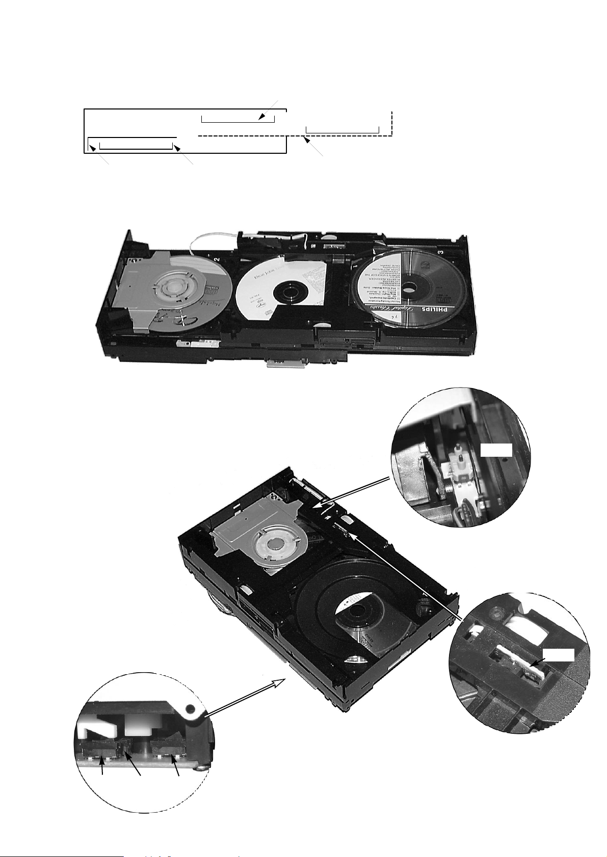
The various states are recognized by seven switches.
For functions see truth table on next page.
2
3
1
Carriage
Carriage extra position
Drawer
Clamper
SW8
SW7
SW6
SW2&3
SW4&5
Location of switches

Truth Table
Slider reverse recognition
Slider forward recognition
Drawer closed recognition
No carriage under clamper
Carriage #1 under clamper
Carriage #2 under clamper
Carriage #3 under clamper
Carriage home recognition
Carriage extra recognition
1
0
0
0
0
0
0
0
0
0
1
0
0
0
0
0
0
0
0
0
1
0
0
0
0
0
0
0
0
0
0
0
1
1
0
0
0
0
0
0
1
0
1
0
0
0
0
0
0
0
0
0
1
0
0
0
0
0
0
0
0
0
1
X
X
X
X
X
X
X
X
X
SW
8
Function
SW7SW6SW5SW4SW3SW2-
Q0 Q1 Q2 Q3 Q4 Q5 Q6 Q7
Register output / Switch
6
 Loading...