

Philips 34PW9818, 30PW9818 User Manual
Color TV
Directions for Use
Color TV
Congratulations on purchasing this Philips product.
We’ve included everything you need to get started.
If you have any problems,Philips Representatives can
help you get the most from your new product by explaining:
• Hookups,
• First Time Setup,and
• Feature Operation.
For fast help,call us first!
1-800-531-0039
Thank you for making Philips a part of your home!
Important!
Return your
Warranty
Registration Card
within 10 days.
See why inside.
3104 315 2176.1
Model No.:
Serial No.:

2
Once your PHILIPS purchase is registered,you’re eligible to receive all the privileges
of owning a PHILIPS product. So complete and return the Warranty Registration
Card enclosed with your purchase at once.And take advantage of these important benefits.
Return your Warranty Registration card today to ensure you
receive all the benefits you’re entitled to.
Congratulations
on your
purchase,
and welcome to the
“family!”
Dear PHILIPS product owner :
Thank you for your confidence in PHILIPS.You’ve selected one of the best-built,best-backed products available
today. And we’ll do everything in our power to keep you happy with your purchase for many years to come.
As a member of the PHILIPS “family,” you’re entitled to protection by one of the most comprehensive warranties and outstanding service networks in the industry.
What’s more,your purchase guarantees you’ll receive all the information and special offers for which
you qualify,plus easy access to accessories from our convenient home shopping network.
And most importantly you can count on our uncompromising commitment to your total satisfaction.
All of this is our way of saying welcome–and thanks for investing in a PHILIPS product.
Sincerely,
Lawrence J.Blanford
President and Chief Executive Officer
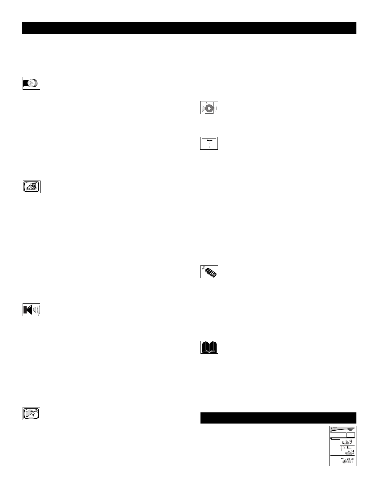
Know these
safetysymbols
t This “bolt of lightning” indicates uninsulated material within your unit may cause an elec-
trical shock.For the safety of everyone in your household,please do not remove product covering.
s The “exclamation point” calls attention to f eatures for which y ou should read the enclosed
literature closely to prevent operating and maintenance problems.
W ARNING:T O PREVENT FIRE OR SHOCK HAZARD ,DO NOT EXPOSE THIS EQUIPMENT
TO RAIN OR MOISTURE.
CAUTION: To prevent electric shock,match wide blade of plug to wide slot, and fully insert.
ATTENTION:Pour éviter les chocs électriques, introduire la lame la plus large de la fiche dans
la borne correspondante de la prise et pousser jusqu’au fond.
CAUTION
RISK OF ELECTRIC SHOCK
DO NOT OPEN
CAUTION: TO REDUCE THE RISK OF ELECTRIC SHOCK, DO NOT
REMOVE COVER (OR BACK). NO USER-SERVICEABLE PARTS
INSIDE. REFER SERVICING TO QUALIFIED SERVICE PERSONNEL.
Warranty
Verification
Registering your product within
10 days confirms your right to maximum protection under the terms and
conditions of your PHILIPS warranty.
Owner
Confirmation
Your completed Warranty
Registration Card serves as
verification of ownership in the
event of product theft or loss.
Model
Registration
Returning your Warranty Registration
Card right away guarantees you’ll
receive all the information and special
offers which you qualify for as the
owner of your model.
P.S. Remember, to get the most from your
PHILIPS product,you must return your
Warranty Registration Card within 10
days.So please mail it to us right now!
R
E
G
I
S
T
R
A
T
I
O
N
N
E
E
D
E
D
W
I
T
H
I
N
1
0
D
A
Y
S
Hurry!
Visit our World Wide Web Site at http://www.philips.com
3
IMPORTANT SAFETY INSTRUCTIONS
Read before operating equipment
1. Read these instructions.
2. Keep these instructions.
3. Heed all warnings.
4. Follow all instructions.
5. Do not use this apparatus near water.
6. Clean only with a dry cloth.
7. Do not block any of the ventilation openings. Install in accordance
with the manufacturers instructions.
8. Do not install near any heat sources such as radiators, heat regis-
ters, stoves, or other apparatus (including amplifiers) that produce
heat.
9. Do not defeat the safety purpose of the polarized or grounding-
type plug. Apolarized plug has two blades with one wider than
the other. A grounding type plug has two blades and third grounding prong. The wide blade or third prong are provided for your
safety. When the provided plug does not fit into your outlet, consult an electrician for replacement of the obsolete outlet.
10. Protect the power cord from being walked on or pinched particu-
larly at plugs, convenience receptacles, and the point where they
exit from the apparatus.
11. Only use attachments/accessories specified by the manufacturer.
12. Use only with a cart, stand, tripod, bracket, or table
specified by the manufacturer, or sold with the app-
aratus. When a cart is used, use caution when moving
the cart/apparatus combination to avoid injury from tip-over.
13. Unplug this apparatus during lightning storms or when unused for
long periods of time.
14. Refer all servicing to qualified service personnel. Servicing is
required when the apparatus has been damaged in any way, such
as power-supply cord or plug is damaged, liquid has been spilled
or objects have fallen into apparatus, the apparatus has been
exposed to rain or moisture, does not operate normally, or has
been dropped.
15. This product may contain lead and mercury. Disposal of these
materials may be regulated due to environmental considerations.
For disposal or recycling information, please contact your local
authorities or the Electronic Industries Alliance: www.eiae.org
16. Damage Requiring Service - The appliance should be serviced
by qualified service personnel when:
A. The power supply cord or the plug has been damaged; or
B. Objects have fallen, or liquid has been spilled into the appli-
ance; or
C. The appliance has been exposed to rain; or
D. The appliance does not appear to operate normally or
exhibits a marked change in performance; or
E. The appliance has been dropped, or the enclosure damaged.
17. Tilt/Stability - All televisions must comply with recommended
international global safety standards for tilt and stability properties
of its cabinet design.
• Do not compromise these design standards by applying excessive pull force to the front, or top, of the cabinet which could ultimately overturn the product.
• Also, do not endanger yourself, or children, by placing electronic equipment/toys on the top of the cabinet. Such items could
unsuspectingly fall from the top of the set and cause product damage and/or personal injury.
18. Wall or Ceiling Mounting - The appliance should be mounted to
a wall or ceiling only as recommended by the manufacturer.
19. Power Lines - An outdoor antenna should be located away from
power lines.
20. Outdoor Antenna Grounding - If an outside antenna is connect-
ed to the receiver, be sure the antenna system is grounded so as to
provide some protection against voltage surges and built up static
charges.
Section 810 of the National Electric Code, ANSI/NFPA No. 701984, provides information with respect to proper grounding of
the mast and supporting structure, grounding of the lead-in wire to
an antenna discharge unit, size of grounding connectors, location
of antenna-discharge unit, connection to grounding electrodes, and
requirements for the grounding electrode. See Figure below.
21. Object and Liquid Entry - Care should be taken so that objects
do not fall and liquids are not spilled into the enclosure through
openings.
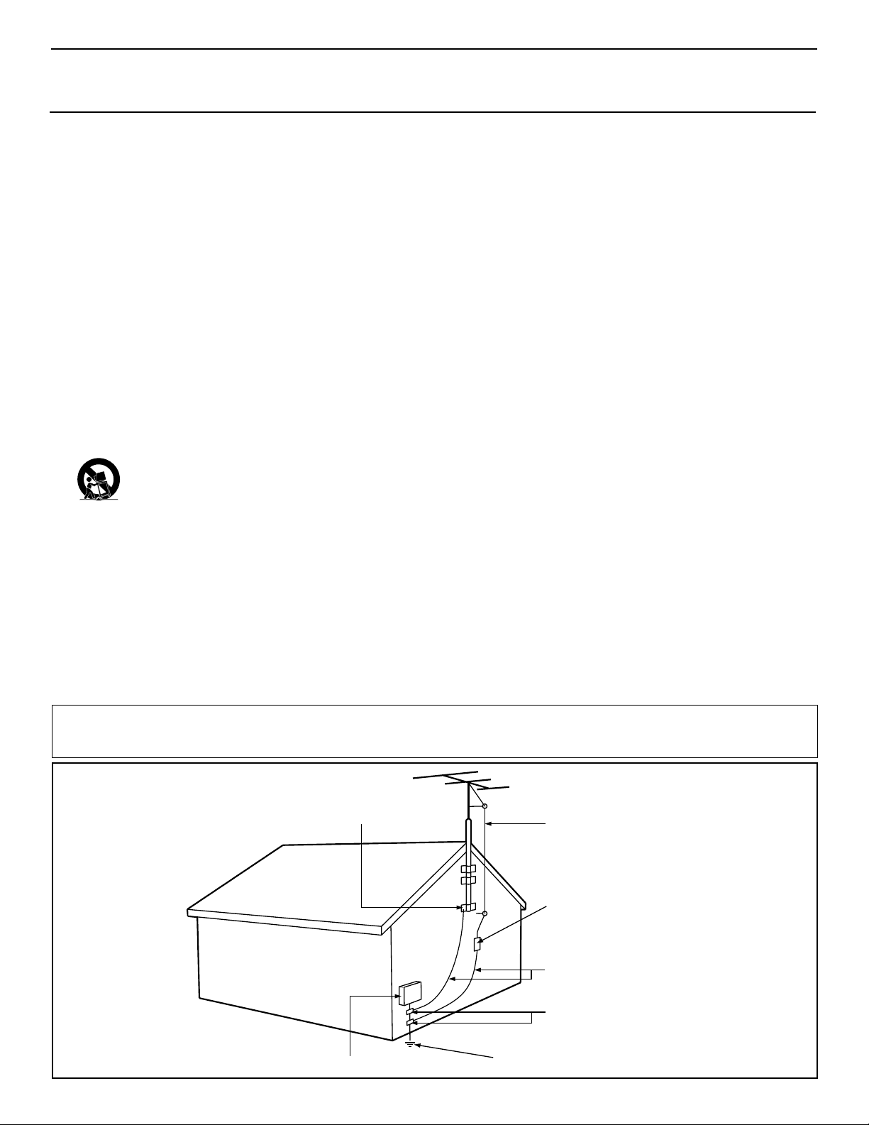
Example of Antenna Grounding
as per NEC - National Electric Code
Note to the CATV system installer:This reminder is provided to call the CATV system installer's attention to Article 820-40 of the NEC that
provides guidelines for proper grounding and,in particular, specifies that the cable ground shall be connected to the grounding system of the building,as close to the point of cable entry as practical.
GROUND CLAMP
ELECTRIC SERVICE EQUIPMENT
POWER SERVICE GROUNDING ELECTRODE SYSTEM (NEC ART 250, PART H)
ANTENNA LEAD IN WIRE
ANTENNA DISCHARGE UNIT
GROUNDING CONDUCTORS (NEC SECTION 810-21)
GROUND CLAMPS
(NEC SECTION 810-20)
4
CONTENTS
INTRODUCTION
Welcome/Registration of Your TV . . . . . . . . . . . . . . . . . . . .2
Safety/Precautions . . . . . . . . . . . . . . . . . . . . . . . . . . . . . .2–3
Features . . . . . . . . . . . . . . . . . . . . . . . . . . . . . . . . . . . . . . . .5
AUDIO/VIDEO INPUT JACKS
Jack Panel descriptions and required cables . . . . . . .6
Using the AV 1 Input Jacks . . . . . . . . . . . . . . . . . . . . . . . . .7
Using the AV 2 Input Jacks . . . . . . . . . . . . . . . . . . . . . . . . .8
Using the Side Input Jacks . . . . . . . . . . . . . . . . . . . . . . . . . .9
Using the AV 3 Input Jacks . . . . . . . . . . . . . . . . . . . . . . . .10
Using the AV 4 Input Jacks . . . . . . . . . . . . . . . . . . . . . . . .11
Using the Component Video Input Jacks (CVI) . . . . . . . . .12
Using the S-Video Input Jack . . . . . . . . . . . . . . . . . . . . . . .13
Using the Monitor Output Jacks . . . . . . . . . . . . . . . . . . . . .14
Using the Audio Output Jacks . . . . . . . . . . . . . . . . . . . . . .15
PICTURE MENU CONTROLS
Adjusting the Contrast Control . . . . . . . . . . . . . . .16
Adjusting the Brightness Control . . . . . . . . . . . . . . . . . . . .16
Adjusting the Color Control . . . . . . . . . . . . . . . . . . . . . . . .16
Adjusting the Sharpness Control . . . . . . . . . . . . . . . . . . . .16
Adjusting the Tint Control . . . . . . . . . . . . . . . . . . . . . . . . .16
How to set the Color Temp Control . . . . . . . . . . . . . . . . . .16
How to use the Pixel Plus (Digital Processing) Control . . .17
How to set the Dynamic Contrast Control . . . . . . . . . . . . .18
How to use the DNR Control . . . . . . . . . . . . . . . . . . . . . . .19
How to use the Color Enhancement Control . . . . . . . . . . .20
How to use the Auto Picture Control . . . . . . . . . . . . . . . . .21
How to set the Picture Format Control . . . . . . . . . . . . . . . .22
SOUND MENU CONTROLS
Adjusting the TV Volume
(and Headphone Volume) . . . . . . . . . . . . . . . . . . . . . . . . . .23
Adjusting the TV Equalizer Control . . . . . . . . . . . . . . . . . .24
How to use the Sound Mode Control . . . . . . . . . . . . . . . . .25
How to use the Alternate Audio Control . . . . . . . . . . . . . . .26
How to set the TV for Stereo programming . . . . . . . . . . . .27
How to use the 3D Surround Effect Control . . . . . . . . . . . .28
How to use the AVL (Automatic Volume Leveler) Control .29
How to use the Delta Volume Control . . . . . . . . . . . . . . . .30
How to use the Auto Sound Control . . . . . . . . . . . . . . . . . .31
FEATURE MENU CONTROLS
How to use the Closed Captions Controls . . . . . . .32
How to use the Sleeptimer Control . . . . . . . . . . . . . . . . . .33
How to use the On-Timer Control . . . . . . . . . . . . . . . . . . .34
Using the Channel List Control . . . . . . . . . . . . . . . . . . . . .35
How to use the Channel Lock Control . . . . . . . . . . . . . . . .36
Using the Lock After Control . . . . . . . . . . . . . . . . . . . . . . .37
How to block programming using the TV Ratings Lock
Controls . . . . . . . . . . . . . . . . . . . . . . . . . . . . . . . . . . . . . . .38
How to block programming using the Movie Ratings
Controls . . . . . . . . . . . . . . . . . . . . . . . . . . . . . . . . . . . . . . .39
Editing channels with the Channel Remove Control . . . . . .40
Using the Antenna Attenuator Control . . . . . . . . . . . . . . . .41
SPEAKER MENU CONTROLS
Using the Test Tone and Speaker Trim Controls . . .42
How to turn the Center Mode and Surround Speakers
Controls on . . . . . . . . . . . . . . . . . . . . . . . . . . . . . . . . . . . .43
GENERAL MENU CONTROLS
How to use the Menu Background Control . . . . . .44
Using the Surf Control (Channel Surf) . . . . . . . . . . . . . . . .45
How to use the Dual Screen Format Control . . . . . . . . . . .46
How to use the Multipip Control . . . . . . . . . . . . . . . . . . . .47
How to use the Freeze Control . . . . . . . . . . . . . . . . . . . . . .48
How to Reset the AV Setting . . . . . . . . . . . . . . . . . . . . . . .49
Using the Tilt Adjust Control . . . . . . . . . . . . . . . . . . . . . . .49
How to Minimize or Maximize the Onscreen Display . . . .50
How to set up the Timer Zone and Daylight
Savings Controls . . . . . . . . . . . . . . . . . . . . . . . . . . . . . . . .50
How to change your PIN (Personal Identification Number)
for AutoLock features . . . . . . . . . . . . . . . . . . . . . . . . . . . .51
How to Label the AV Sources . . . . . . . . . . . . . . . . . . . . . .52
REMOTE CONTROL RELATED FEATURES
Using the Active Control . . . . . . . . . . . . . . . . . . . .53
How to use the Zoom Control . . . . . . . . . . . . . . . . . . . . . .53
Using the Remote Control with accessory devices
Code-Entry Method . . . . . . . . . . . . . . . . . . . . . . . . . . . . .54
Search Method . . . . . . . . . . . . . . . . . . . . . . . . . . . . . . . .55
Direct-Entry Code list for accessory devices . . . . . . . . .56-57
Remote Control VCR Specific Button . . . . . . . . . . . . . . . .58
IMPORTANT INFORMATION
Care and Cleaning . . . . . . . . . . . . . . . . . . . . . . . . .59
Troubleshooting . . . . . . . . . . . . . . . . . . . . . . . . . . . . . . . . .59
Glossary of terms . . . . . . . . . . . . . . . . . . . . . . . . . . . . . . . .60
Index . . . . . . . . . . . . . . . . . . . . . . . . . . . . . . . . . . . . . . . . .61
Limited Warranty . . . . . . . . . . . . . . . . . . . . . . . . . . . . . . . .62
Refer to the simple Quick Use and Setup
Guide (supplied with your TV) for details
on Basic Connections, Remote Control
Operation, Language and Auto Program.
QUICK USE AND SETUP GUIDE
b
P
1
2
b
P
1
3
2
General Source
Settings
Menu background
Surf
Dual screen format
Multipip format
Quick Use and Setup Guide
Important Notice/Warning . . . . . . . . . . . . . . . . . . . .1
Making Basic TVConnections
Basic Cable TVConnections . . . . . . . . . . . . . . . . .1
Basic Antenna TVConnections . . . . . . . . . . . . . . .1
Basic TVOperation . . . . . . . . . . . . . . . . . . . . . . . .2
Remote Battery Installation . . . . . . . . . . . . . . . . . . .2
Remote Control Button Descriptions . . . . . . . . . . . .2
CABLETV
our Cable TVinput into your home may be a single (75 ohm)
Y
cable or a converter box installation. In either case, the connection to the TVis very easy. Follow the steps below to connect
your cable signal to your new television.
If yourcable signal comes directly from a round 75Ωcoaxial
cable use the following steps:
Connect the open end of the round Cable Company sup-
plied cableto the 75Ωinputon the TV. Screw it down finger
1
tight.
Plug the television in to the wall outletand turn the TVon.
Refer to the AUTOPROGRAM feature to program all the
2
available channels on your cable signal.
If yourcable signal comes from a cable box, use the following
steps:
Connect the open end of the round Cable Company sup-
the cable signal IN(put) plug on the back of
plied cable to
3
the Cable Box.
Using a separate round coaxial cable, connect one end to the
OUT(put) plug on the back of the Cable Box.
4
Connect the otherend of the round coaxial cableto the
75Ωinput on the back of the television. Screw it down finger
5
tight.
Plug the television in to the wall outletand turn the TVon.
Refer to the TUNER and AUTOPROGRAM features on page
6
3 of this Quick Use Guide. TUNER should be set to the
CABLE option. AUTOPROGRAM can be set to program all
the available channels on your cable signal into the televi-
sion’s memory.
ANTENNATV
combination antenna receives normal broadcast chan-
nels (VHF 2–13 and UHF 14–69). Your connection is
A
easy because there is only one 75Ω(ohm) antenna plug on
the back of your TV, and that’s where the antenna goes.
If yourantenna has a round cable(75 ohm) on the end,
then you're ready to connect it to the TV.
1
If yourantenna has flat, twin-lead wire (300 ohm), you
first need to attach the antenna wires to the screws on a
300- to 75-ohm adapter.
Push the round endof the adapter (or antenna) onto the
75Ω(ohm) plug on the back of the TV. If the round end of
2
the antenna wire is threaded, screw it down finger tight.
Plug the television in to the wall outletand turn the TV
Refer to the TUNER and AUTOPROGRAM features on
on.
3
page 3 of this Quick Use Guide. TUNER should be set to the
ANTENNAoption. AUTOPROGRAM can be set to program
all the available channels on your cable signal into the televi-
sion’s memory.
CONTENTS
How to Use the Installation Features . . . . . . . . . .3-4
Using the Language Control . . . . . . . . . . . . . . . . . .3
Setting the Tuner Mode Control . . . . . . . . . . . . . . .3
How to Automatically Program Channels . . . . . . . .3
How to Add and Delete Channels . . . . . . . . . . . . . .4
How to set the AutoChron™Feature (Clock) . . . . .4
How to Name (Label) Channels . . . . . . . . . . . . . . . .4
BASICTV CONNECTIONS
Direct Cable Connection:
Cable Box Connection:
Antenna Connection:
broadcast channels 2-13 (VHF) and 14-69 (UHF).
Color TV
Color TV
IMPORTANT
NOTE: This owner's manual is used with several
different television models. Not all features (and
drawings) discussed in this manual will necessarily match those found with yourtelevision set.
This is normal and does not require that you contact yourdealerorrequest service.
WARNING: TO PREVENTFIRE OR SHOCK
HAZARD DO NOTEXPOSE THIS UNITTO
RAIN OR EXCESSIVE MOISTURE.
AC Power
Cable signal coming from
Wall Outlet
Cable Company (Round
75Ωcoaxial cable)
Power Plug
from back of TV
Jack Panel Back of TV
Jack Panel Back
4
3
of Cable Box
INPUT
OUTPUT
AC Power
Wall Outlet
Round 75Ω
Coaxial Cable
6
b
Jack Panel
Cable Signal IN from
Back of TV
the Cable Company
P
5
Power Plug
from back of TV
Outdoor or Indoor Antenna
(Combination VHF/UHF)
AC Power
Jack Panel
The combination antenna receives normal
Wall Outlet
Back of TV
300 to 75-ohm
Adapter
Twin
Lead Wire
Power Plug
from back of TV
Round 75Ω
Coaxial Cable
from Antenna
3121 233 42241

5
Items Included with This TV
FEATURES
Active Control™ continuously measures and corrects all incoming signals to help provide the best picture quality. This feature
monitors and corrects both the sharpness control and noise
reduction control.
Audio/Video Jack Panel allows direct connections with VCRs,
DVDs, High Definition Receivers or other devices, providing
quality TV picture and sound playback.
Audio Volume Leveler (AVL) Control keeps the TV sound at
an even level. Peaks and valleys that occur during program
changes or commercial breaks are reduced, making for a more
consistent, comfortable sound.
Channel Lock allows you to block the viewing of certain channels or programs with certain ratings if you do not want your
children to view inappropriate materials.
Auto Programming scans (when activated) for all available
channels from regular antenna or cable signals and stores only
active broadcast stations in the TV’s memory.
AutoPicture™ allows you to change the picture settings (color,
tint, contrast, etc.) for various types of programming, such as
sports, movies, multimedia (games), or weak signals with the
push of one button. Selections include, Personal, Rich, Natural,
Soft, Multimedia, or Eco.
AutoSound™ allows you to change to different factory predefined audio settings and a personal control that you set according to your own preferences through the onscreen Sound menu.
The five factory-set controls (Personal, Speech, Music, Movie,
and Multimedia) enable you to tailor the TV sound so as to
enhance the particular programming you are watching.
Channel Remove allows you to delete channels from the list
stored in the TV’s memory. Channel Remove makes it easy to
limit the number of channels that are available to you when you
press the Channel (+) or (–) buttons on your remote control.
Closed Captioning allows the viewer to read TV program dialogue or voice conversations as onscreen text.
Dynamic Contrast helps to sharpen the picture quality by
improving the contrast between the darkest and brightest parts of
the picture.
Pixel Plus™ (or Digital Processing) gives a choice of two different scanning techniques – Progressive Scan or Pixel Plus.
Progressive Scan doubles the number of picture lines, eliminating line flicker and providing a jitter-free picture.
Pixel Plus™improves the appearance of onscreen motion.
The number of picture lines are increased along with the
number of pixels per line, giving normal broadcast signals,
DVD reproduction or Digital TV signals, unparalleled sharpness and depth. Gives the viewer near High Definition and
natural looking detail without the High Definition signal.
Infrared Remote Control works your TV and other remotecontrolled devices, such as VCRs, DVD players, cable converters, satellite receivers, etc.
Onscreen Menu shows helpful messages and instructions for
setting TV feature controls (can be viewed in English, French, or
Spanish).
Your new television and its packing contain materials that
can be recycled and reused. Specialized companies can recycle your product to increase the amount of reusable materials
and minimize the amounts that need to be properly disposed.
Your product also uses batteries that should not be thrown
away when depleted, but should be handed in and disposed of
as small chemical waste.
When you replace your existing equipment, please find out
about the local regulations regarding disposal of your old television, batteries, and packing materials.
END-OF-LIFE DISPOSAL
Sleep Timer automatically turns the TV OFF after a set amount
of time that you choose.
Standard Broadcast (VHF/UHF) or Cable TV (CATV) channel capability allows for viewing by antenna or cable.
Stereo capability, including a built-in audio amplifier and twinspeaker system, allows for the reception of TV programs broadcast in stereo sound.
Surf Button allows you to easily switch among only the channels that are of interest to you (the ones that you have programmed into the TV’s Surf control through the onscreen menu).
Surf allows 2 channel surfing or 9 channel surfing.
Timer allows you to set your TV to turn itself ON and OFF
once or daily like an alarm clock.
As an Energy Star® Partner, Philips Consumer
Electronics has determined this product meets
the Energy Star® guidelines for energy efficiency. Energy Star® is a U.S. registered mark. Using products
with the Energy Star® label can save energy. Saving energy
reduces air pollution and lowers utility bills.
Active Control, AutoPicture, AutoSound, Pixel Plus are
trademarks of Philips Consumer Electronics Company.
Copyright 2002 Philips Consumer Electronics.
As you unpack your TV, please note the included items:
• Directions for Use manual (contains safety-tip, clean-
ing and Factory Service Center location information)
• Warranty Registration Card
• Remote Control (with supplied batteries for use)
• Quick Use Guide to help you set up your new TV.
Please take a few minutes to complete your registration
card. The serial number for the TV is on the rear of the set.
For your future reference, please write down the serial and
model number of this television in the space provided on the
cover of this manual. (In the unlikely event you should need
to place a service call, these numbers will be needed.)
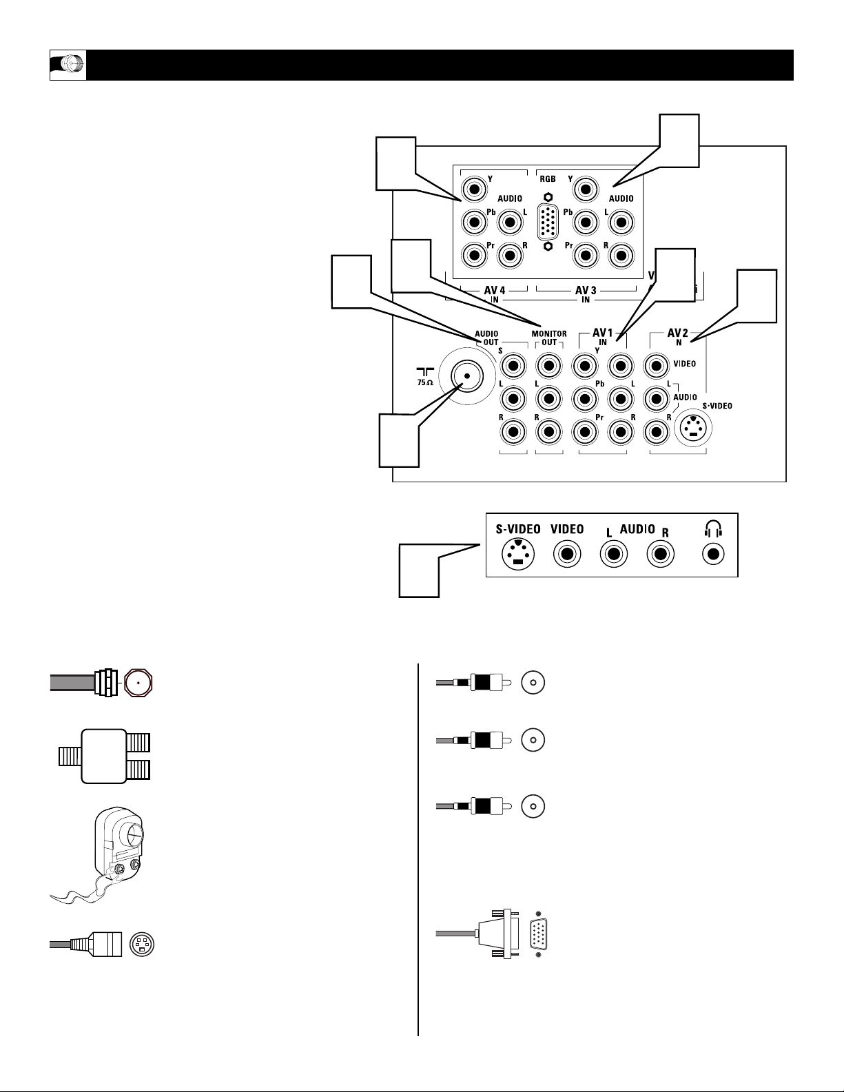
6
T
he television is equipped with external
input and output jacks for use with optional
accessory devices such as Home entertainment
Receivers, VCRs, DVD Player, Gaming Units,
Video Cameras, etc. The following gives a brief
explanation of the different types of jacks available and the type of cables needed to make
connections.
1
75Ω RF - Cable/Antenna Input connection jack.
2
AV 1 IN - Audio/Video connection jacks
including Component Video Inputs.
3
AV 2 IN - Audio/Video Input connection
jacks including S-Video connections.
4
AV 3 IN - Component Video, VGA
(RGB), and Audio Input connection
jacks.
5
AV 4 IN - High Definition Component
Video and Audio Input connection jacks.
6
Monitor Out - Audio/Video Output
connection jacks (TV tuner signal only).
7
Audio Out - Audio connections for
home entertainment receivers and external speakers.
8
SIDE - Audio/Video Input jacks include
a S-Video jack, plus a Headphone jack
located on the side of the cabinet.
JACK P
ANEL DESCRIPTIONS AND REQUIRED CABLES
A 75-ohm coaxial cable connects signals
from an antenna or a cable TV company
to the antenna jack on the back of the TV.
Coaxial cables use “F” connectors.
A two-way signal splitter enables you to
take a single antenna or cable TV signal
and supply it to two different inputs.
A 300- to 75-ohm twin-lead adapter
accepts the antenna cables (called twinlead wires) from an antenna, allowing you
to connect the antenna signal to the TV.
A S-Video cable provides better picture
performance than regular (composite)
video connections.
S-Video cables can be used only with SVideo-compatible accessory devices. You
must also connect the left and right audio
cables to the AV 2 Audio in jacks because
the S-Video jack carries only the picture
signal, not the sound.
Video and audio cables with standard
RCA (phono) connectors connect the
video and audio jacks of accessory
devices such as VCRs and DVD players
to the jacks on the TV.
These connectors are usually color coded.
The jacks on your TV are also color
coded to match the colors of the connectors. Yellow for video (composite) and
Red and White for the right and left audio
channels. The video cables used to connect component video or RGB (high-resolution) jacks are color coded red, green,
and blue.
A VGA (HD15) cable makes a VGA
(RGB) connection to the HD INPUT-AV
4 jack on the rear of the TV.
Cable Descriptions:
Yellow - Video
White - Audio Left
Red - Audio Right
7
5
6
1
Located on the back of the TV
4
2
3
8
Located on the side of the TV
7
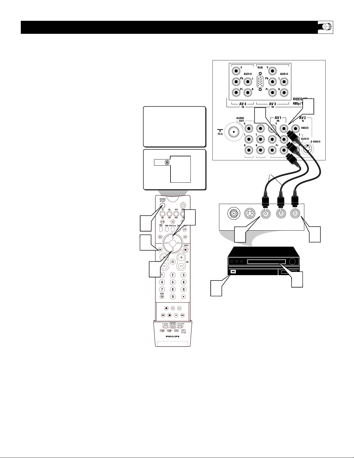
T
he TV’s audio/video input jacks are for
direct picture and sound connections
between the TV and a VCR (or similar device)
that has audio/video output jacks. Follow the
easy steps below to connect your accessory
device to the AV 1 Input Jacks located on the
back of the TV.
1
Connect the VIDEO (yellow) cable to
the VIDEO AV1 IN jack on the back of
the TV.
2
Connect the AUDIO (red and white)
cables to the AUDIO (left and right)
AV1 IN jacks on the rear of the TV.
3
Connect the VIDEO (yellow) cable to
the VIDEO OUT jack on the back of
the VCR.
4
Connect the AUDIO (red and white)
cables to the AUDIO (left and right)
OUT jacks on the rear of the VCR.
5
Turn the VCR (accessory device) and
the TV ON.
6
Press the SOURCE SELECT button
on the remote control to display the
SOURCE menu.
7
Press the CURSOR UP or DOWN
button to select the AV1 option.
8
Press the OK button to confirm your
selection. The TV will change to the
AV1 channel.
USING THE AV 1 I
NPUT JACKS
AUDIO IN
(RED/WHITE)
VCR
(EQUIPPED WITH VIDEO AND
AUDIO OUTPUT JACKS)
VIDEO IN
(YELLOW)
BACK OF VCR
BACK OF TV
AV1
1
2
6
8
7
Source
TV
AV1: VCR
AV2: Recorder
AV3: DVD
AV4: HD
SIDE: Camera
ACITVE
CONTROL
SOUND PICTURE
R L
AUDIO OUT
VIDEO
OUT
7
3
7
ANT/CABLE
OUT
S-VIDEO
OUT
4
5
ZOOM
AUDIO IN
(RED/WHITE)
SECOND VCR
or ACCESSORY DEVICE
(EQUIPPED WITH VIDEO
AND AUDIO OUTPUT JACKS)
VIDEO IN
(YELLOW)
BACK OF 2ND VCR
BACK OF TV
8
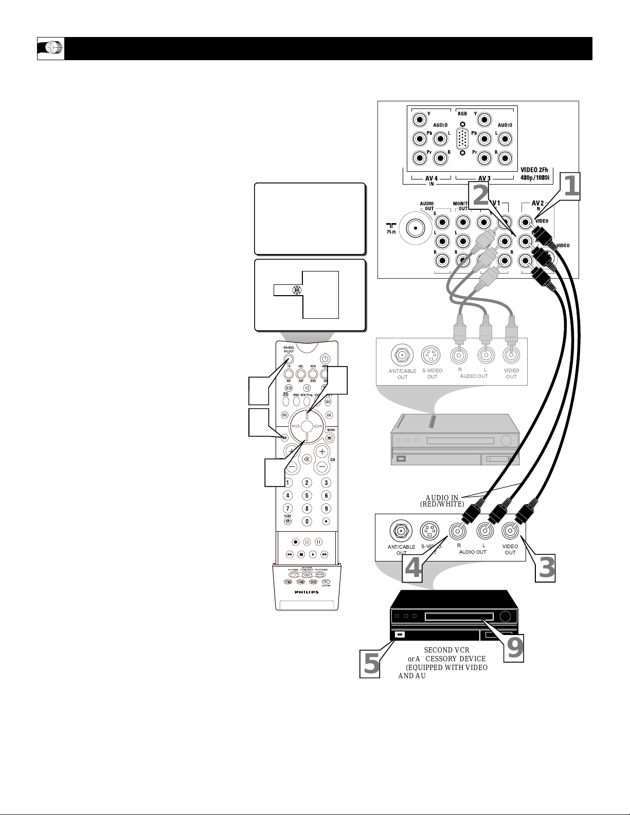
T
he TV’s audio/video input jacks allow you
connect multiple accessory devices at one
time to different sets of input jacks.. Follow
the easy steps below to connect an additional
accessory device to the AV 2 Input Jacks located on the back of the TV.
1
Connect the VIDEO (yellow) cable to
the VIDEO AV2 IN jack on the back of
the TV.
2
Connect the AUDIO (red and white)
cables to the AUDIO (left and right)
AV2 IN jacks on the rear of the TV.
3
Connect the VIDEO (yellow) cable to
the VIDEO OUT jack on the back of
the VCR.
4
Connect the AUDIO (red and white)
cables to the AUDIO (left and right)
OUT jacks on the rear of the VCR.
5
Turn the VCR (accessory device) and
the TV ON.
6
Press the SOURCE SELECT button
on the remote control to display the
SOURCE menu.
7
Press the CURSOR UP or DOWN
button to select the AV2 option.
8
Press the OK button to confirm your
selection. The TV will change to the
AV2 channel.
9
With the VCR (or accessory device)
ON and a prerecorded tape (or other
media depending on type of accessory
device being used) inserted, press the
PLAY button to view the tape on the
television.
USING THE AV 2 I
NPUT JACKS
FIRST VCR
CONNECTED TOAV1 INPUTS
AV2
TV
AV1: VCR
Source
AV2: Recorder
AV3: DVD
AV4: HD
SIDE: Camera
1
2
6
8
7
ACITVE
CONTROL
SOUND PICTURE
ANT/CABLE
OUT
S-VIDEO
OUT
RL
AUDIO OUT
VIDEO
OUT
7
OUT
RL
AUDIO OUT
VIDEO
OUT
9
OUT
S-VIDEO
ANT/CABLE
ZOOM
4
5
3
9
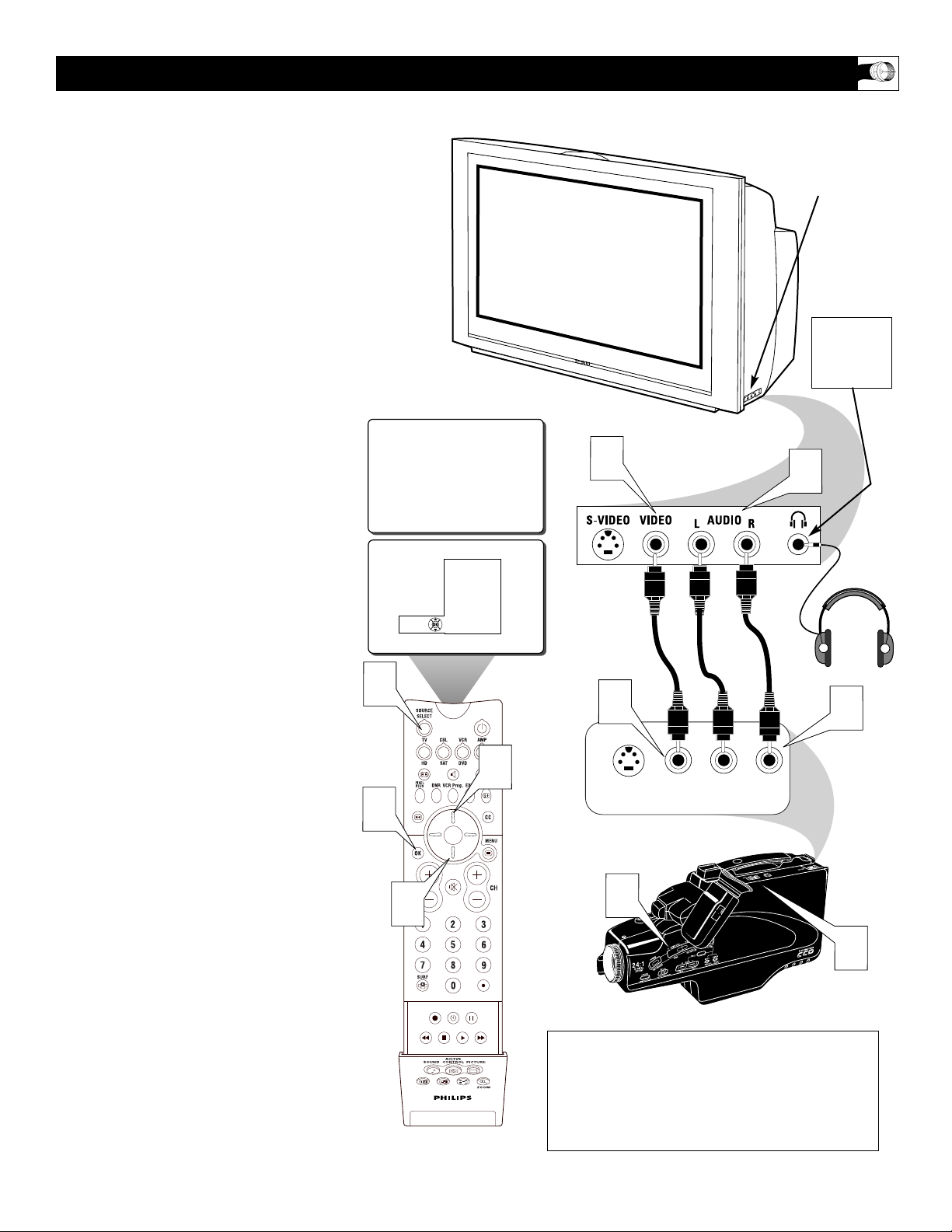
T
his television has input jacks conveniently
located on the side of the cabinet. These
jack are for easy hook-ups (without having to
move around to the back of the TV) for cameras, gaming units, and other accessory
devices that wouldn’t be connected permanently. Follow the easy steps below to connect
your accessory device to the SIDE Input Jacks
located on the right side of the TV.
1
Connect the VIDEO (yellow) cable to
the VIDEO IN jack on the side of the
TV.
2
Connect the AUDIO (red and white)
cables to the AUDIO (left and right)
IN jacks on the side of the TV.
3
Connect the VIDEO (yellow) cable to
the VIDEO OUT jack on the back of
the camera (or accessory device).
4
Connect the AUDIO (red and white)
cables to the AUDIO (left and right)
OUT jacks on the rear of the camera
(or accessory device).
5
Turn the camera (or accessory
device) and the TV ON.
6
Press the SOURCE SELECT button
on the remote control to display the
SOURCE menu.
7
Press the CURSOR UP or DOWN
button to select the SIDE option.
8
Press the OK button to confirm your
selection. The TV will change to the
SIDE channel.
9
With the camera (or accessory device)
ON and a prerecorded tape (or other
media depending on type of accessory
device being used) inserted, press the
PLAY button to view the tape on the
television.
USING THE SIDE I
NPUT JACKS
VIDEO IN
(YELLOW)
NOTE: The S-Video Cable can be used in place of
the Yellow Video cable shown in this diagram. If
your camera or accessory device has a S-Video
output jack, connecting the video signal through
the S-Video jack will reproduce the video signal
with greater quality.
AUDIO IN
(RED &
WHITE)
Jack Panel of
Camera
or External
Accessory Device
SIDE (AV 3) Input Jacks
Located on the Side of
the Television Cabinet
The SIDE
JACKS also
contain a
HEADPHONE
JACK.
6
8
SIDE
Source
SIDE
TV
AV1: VCR
AV2: Recorder
AV3: DVD
AV4: HD
SIDE: Camera
7
1
3
S-VIDEO
VIDEO
AUDIO
LEFT RIGHT
2
4
7
ACITVE
CONTROL
SOUND PICTURE
9
5
ZOOM
10
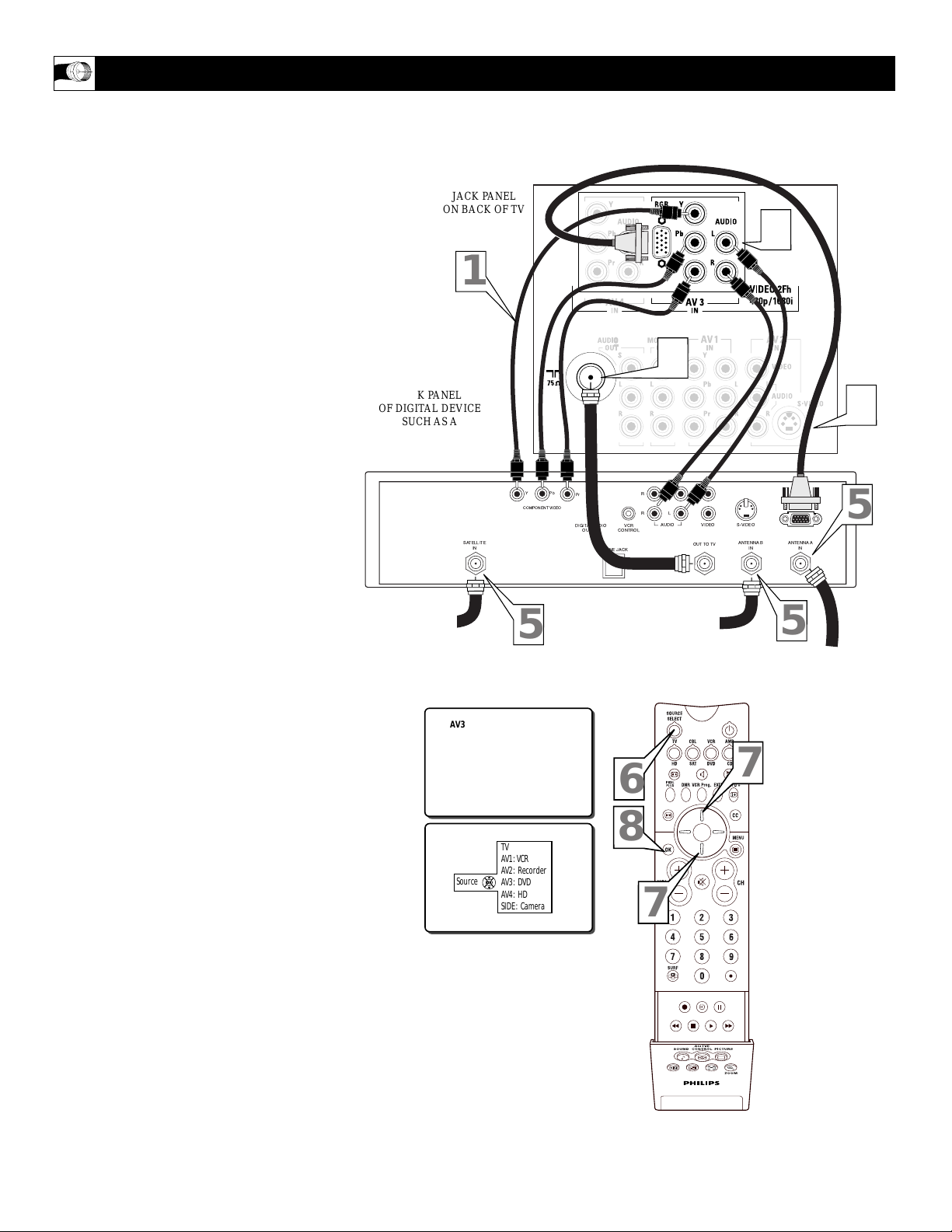
T
he AV3 Input Jacks provide Both Component
and RGB Video Inputs at 1080i, for accessories like a HD Receiver and Digital DVD
Players. Using the color difference signals (Pb,
Pr) and the luminance (Y) signal will improve
color bandwidth information. The TV can also
become a monitor for projectors, computers or
HD Receivers using the RGB Input.
1
Connect the Component (Y, Pb, Pr)
Video OUT jacks from the DVD player
(or similar device) to the (Y, Pb, Pr) AV3
IN(put) jacks on the TV.
2
Connect the red and white AUDIO
CABLES to the Audio (left and right)
output jacks on the rear of the accessory
device to the Audio (Land R) AV3
IN(put) jacks on the TV.
3
Connect a RGB cable from the VGA
OUT on the HD Receiver to the AV3
RGB Input jack on the back of the TV.
4
Connect a 75Ω round cable from the
OUT TO TV jack on the HD Receiver to
the 75Ω IN on the back of the TV.
5
If using a Satellite Dish, Cable signal or
Antenna signal, connect the 75Ω round
cable from a Satellite Dish to the SATELLITE IN and/or the Cable and Antenna
signals to the ANTENNA“A” or “B” IN
on the back of the HD Receiver.
6
Press the SOURCE SELECT button
on the remote control to display the
SOURCE menu.
7
Press the CURSOR UP or DOWN
button to select the AV3 option.
8
Press the OK button to confirm your
selection. The TV will change to the
AV3 channel.
USING THE AV 3 I
NPUT JACKS
JACK PANEL
ON BACK OF TV
JACK PANEL
OF DIGITAL DEVICE
SUCH AS A
PROGRESSIVE SCAN
DVD PLAYER
OR HD RECEIVER
Note: If the AV3 channel is tuned and no signal
connection present, the screen could jump or flash.
AUDIO IN
(RED/WHITE)
COMPONENT
VIDEO
CABLES
RGB CABLE
COAXIAL CABLE
LEAD-IN FROM
SATELLITE DISH
COAXIAL CABLE LEAD-IN
FROM ALTERNATE RF
SIGNAL SOURCE
COAXIAL CABLE
LEAD-IN FROM CABLE
OUTLET, CONVERTER BOX,
OR VHF/UHF ANTENNA
1
Y
Pb
Pr
DIGITALAUDIO
OUTPUT
PHONE JACK
Coaxial Cable
Lead-in from
Satellite Dish
AV3
SATELLITE
IN
COMPONENTVIDEO
5
4
L
R
L
R
VCR
CONTROL
Coaxial Cable Lead-in
from Alternate RF
Signal Source
VIDEOAUDIO
OUTTO TV
2
3
S-VIDEO
ANTENNABINANTENNAA
IN
5
5
Coaxial Cable
Lead-in from Cable Outlet,
Converter Box,
or VHF/UHF Antenna
Source
TV
AV1: VCR
AV2: Recorder
AV3: DVD
AV4: HD
SIDE: Camera
6
8
7
ACITVE
CONTROL
SOUND PICTURE
7
ZOOM
11
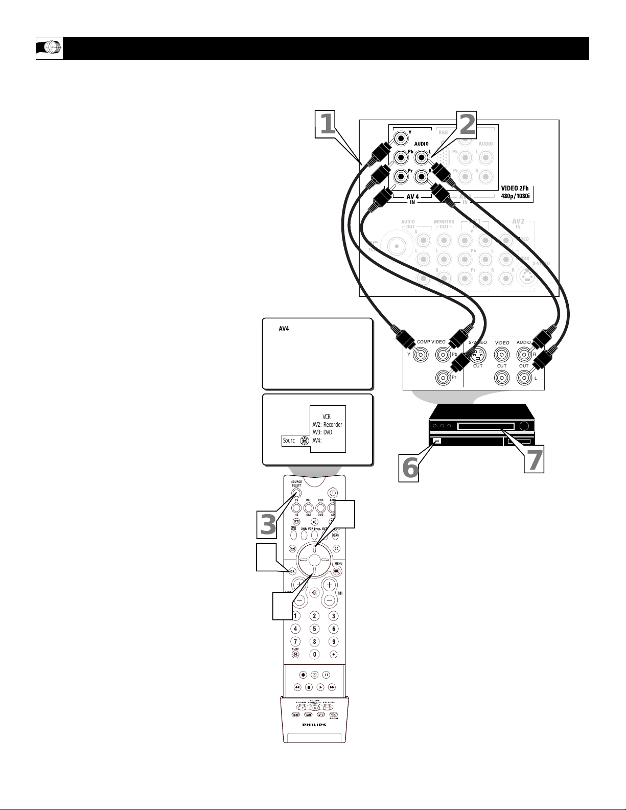
T
he AV4 Input Jacks provide Component Video
Inputs at 1080i, for accessories like a HD
Receiver and Digital DVD Players. Using the
color difference signals (Pb, Pr) and the luminance (Y) signal will improve color bandwidth
information.
1
Connect the Component (Y, Pb, Pr)
Video OUT jacks from the DVD player
(or similar device) to the (Y, Pb, Pr) AV4
IN(put) jacks on the TV.
2
Connect the red and white AUDIO
CABLES to the AUDIO (left and right)
OUT(put) jacks on the rear of the accessory device to the Audio (Land R) AV4
IN(put) jacks on the TV.
3
Press the SOURCE SELECT button
on the remote control to display the
SOURCE menu.
4
Press the CURSOR UP or DOWN
button to select the AV3 option.
5
Press the OK button to confirm your
selection. The TV will change to the
AV3 channel.
6
Turn the TV and the DVD (or digital
accessory device) ON.
7
Press the PLAY button on the DVD (or
digital accessory device) to view the program on the television.
USING THE AV 4 I
NPUT JACKS
JACK PANEL
ON BACK OF TV
JACK PANEL
OF DIGITAL DEVICESUCH
AS A DVD PLAYER
EQUIPPED WITH
COMPONENT VIDEO
OUTPUTS
Note: If the AV4 channel is tuned and no signal connection present, the screen could jump or flash.
AUDIO IN
(RED/WHITE)
COMPONENT
VIDEO
CABLES
1
AV4
Y
COMP VIDEO
Pb
Pr
2
S-VIDEO
OUT
AUDIO
VIDEO
OUT
OUT
R
L
3
5
4
Source
TV
AV1: VCR
AV2: Recorder
AV3: DVD
AV4: HD
SIDE: Camera
ACITVE
CONTROL
SOUND PICTURE
6
7
4
ZOOM
12
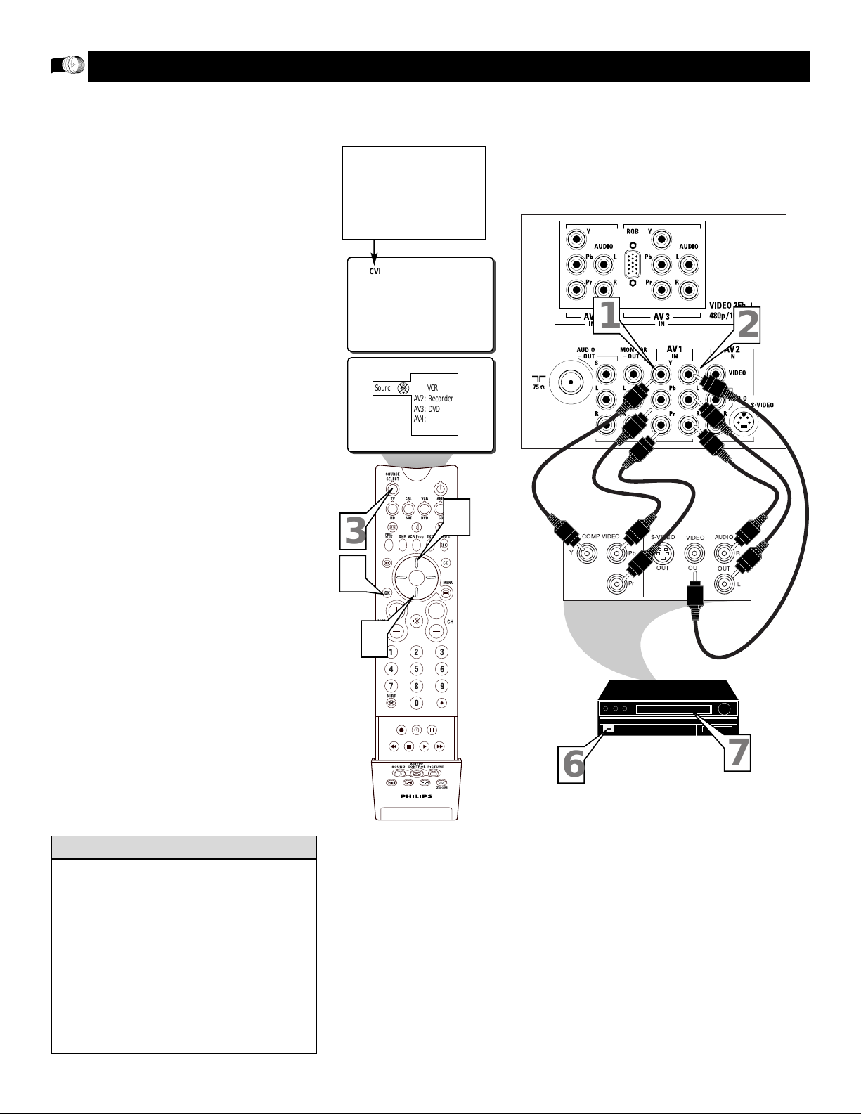
I
f using an accessory device that is not high
definition but uses Component Video jacks.
The AV1 jacks on the TV offer the user the
possibility of better video reproduction using
the Component Video Inputs. The color difference signals (Pb, Pr) and the luminance
(Y) signal are connected and received separately, which allows for improved color bandwidth information (not possible when using
composite video or S-Video connections).
1
Connect the Component (Y, Pb, Pr)
Video OUT jacks from the DVD play-
er (or similar device) to the (Y, Pb, Pr)
IN(put) jacks on the TV. When using
the Component Video Inputs, it is best
not to connect a signal to the AV1
Video Input.
2
Connect the yellow VIDEO CABLE
along with the red and white AUDIO
CABLES to the AUDIO (left and
right) OUT(put) jacks on the rear of the
accessory device to the AV1 VIDEO
and AUDIO IN(put) jacks on the TV.
3
Press the SOURCE SELECT button
on the remote control to display the
SOURCE menu.
4
Press the CURSOR UP or DOWN
button to select the AV1 option. CVI
will show onscreen rather than AV1.
5
Press the OK button to confirm your
selection. The TV will change to the
AV1 channel.
6
Turn the TV and the DVD (or digital
accessory device) ON.
7
Insert a DVD disc into the DVD player
and press the PLAY 䊳 button on the
DVD Player (or digital accessory
device).
USING THE C
OMPONENT VIDEO INPUT (AV1) JACKS
The description for the component video
connectors may differ depending on the
DVD player or accessory digital source
equipment used (for example, Y, Pb, Pr; Y,
B-Y, R-Y; Y, Cr, Cb). Although abbreviations and terms may vary, the letters b and r
stand for the blue and red color component
signal connectors, and Y indicates the luminance signal. Refer to your DVD or digital
accessory owner’s manual for definitions
and connection details.
HELPFUL HINT
AUDIO IN
(RED/WHITE)
COMPONENT
VIDEO
CABLES
BACK OF TV
ACCESSORY DEVICE
EQUIPPED WITH
COMPONENT VIDEO
OUTPUTS.
The CVI connection will be
dominate over the AV1 Video
Input. When a Component Video
Device is connected as described,
it is best not to have a video sig-
nal connected to the AV1 Video
Input jack.
VIDEO
(YELLOW)
CABLE
CVI
1
TV
Source
AV1: VCR
AV2: Recorder
AV3: DVD
AV4: HD
SIDE: Camera
3
4
5
COMP VIDEO
Y
S-VIDEO
VIDEO
Pb
OUT
Pr
4
AUDIO
OUT
OUT
2
R
L
ACITVE
CONTROL
SOUND PICTURE
ZOOM
6
7
13
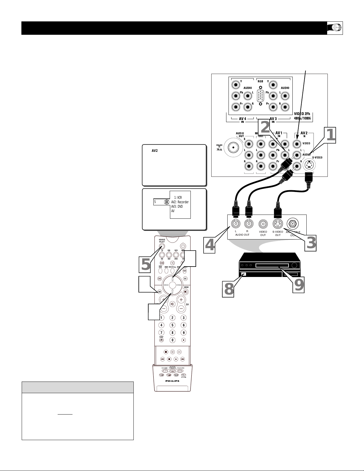
T
he S(uper)-Video connection on the rear
of the TV can provide you with better picture detail and clarity for the playback of
accessory sources such as DBS (digital
broadcast satellite), DVD (digital video
discs), video games, and S-VHS VCR (video
cassette recorder) tapes than the normal
antenna picture connections.
NOTE: The accessory device must have an
S-VIDEO OUT(put) jack in order for you to
complete the connection on this page.
1
Connect the S-VIDEO CABLE to the
S-VIDEO input jack on the rear of the
television.
2
Connect the AUDIO (red and white)
cables to the AUDIO AV2 IN jacks on
the rear of the TV
.
3
Connect the S-VIDEO CABLE to the
S-VIDEO OUT(put) jack on the accessory device.
4
Connect the red and white AUDIO
cables to the AUDIO (left and right)
OUT(put) jacks on the rear of the
accessory device.
5
Press the SOURCE SELECT button
on the remote control to display the
SOURCE menu.
6
Press the CURSOR UP or DOWN
button to select the AV2 option.
7
Press the OK button to confirm your
selection. The TV will change to the
AV2 channel.
8
Turn the VCR, DVD or other accessory device ON.
9
With the VCR (or accessory device)
ON and a prerecorded tape inserted,
press the PLAY button to view the
tape on the television.
USING THE S-V
IDEO INPUT JACKS
The S-Video jack and the AV 2 jacks work
together. When a device is connected to the
S-Video jack, do not connect a signal to the
AV 2 IN Video jack. This could cause an
over-lapping of two video images on the TV
screen.
cc
C
HECK IT OUT
JACK PANEL
ON BACK OF TV
AUDIO CABLES
(Red & White)
S-VIDEO CABLE
VCR or EXTERNAL
ACCESSORY DEVICE
WITH S-VIDEO OUTPUT
When using the S-Video Input, do not
connect a video signal to the AV 2 IN
Video Jack. This could cause a ghost
image to appear over the S-Video signal.
5
7
AV2
6
Source
TV
AV1: VCR
AV2: Recorder
AV3: DVD
AV4: HD
SIDE: Camera
6
4
8
2
LR
AUDIO OUT
VIDEO
OUT
S-VIDEO
OUT
ANT/CABLE
OUT
3
9
1
ACITVE
CONTROL
SOUND PICTURE
ZOOM
14
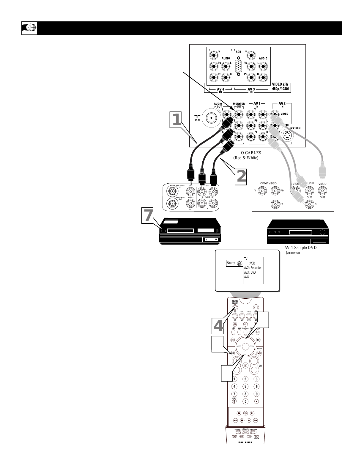
T
he Audio/Video (Monitor) Output jacks
can be used for recording a selected TV
(Antenna Input/tuner signal source) Channel.
This recording can even be completed while
viewing another external Audio/Video Source
Select option. (For example: DVD program
playback shown through the A/V 1 or 2 Input
source connection.)
NOTE: Refer to page 7 for the proper
hookup of an accessory device to the AV 1
IN(put) jacks. Follow the instructions on how
to tune to the AV 1 channel to view a DVD
program playback or pre-recorded VCR tape.
The following steps allow you to connect a
VCR to record a selected TV channel pro-
gram through the Monitor Outputs.
1
Connect one end of the yellow Video
Cable to the Monitor Out VIDEO
plug. Connect the other end to the
VIDEO IN plug on the VCR.
2
Connect one end of the red and white
Audio cable from the Monitor Out
AUDIO L and R plugs on the TV to the
AUDIO IN plugs on the VCR.
3
Tune the TV to the program channel
you wish to record.
Note: Once selected be sure to leave
the TV channel tuned to the desired
program until the complete recording is
finished.
4
Press the SOURCE SELECT button
on the remote control to display the
SOURCE menu.
5
Press the CURSOR UP or DOWN
button to select the AV1 option (or any
of the other AV connection options
from which you wish towatch an
accessory device playback. Example:
DVD playback on AV 1).
6
Press the OK button to confirm your
selection. The TV will change to the
AV1 channel input (or any other source
option you wish to select).
7
Turn the VCR ON, insert a blank
VHS tape and it’s ready to record the
channel program you selected previously in step #3.
USING THE M
ONITOR OUTPUT JACKS
JACK PANEL
Located on the
back of the TV
AUDIO CABLES
(Red & White)
AV 1 Sample DVD
(accessory device
Hookup from Page 7)
MONITOR OUT
VIDEO &
AUDIO L(eft) and R(ight)
Recording VCR
VIDEO CABLE
(Yellow)
1
7
ANTENNA
IN
ANTENNA
OUT
OUT OUT
VIDEO
IN
AUDIO
2
RL
IN
Source
Y
TV
AV1: VCR
AV2: Recorder
AV3: DVD
AV4: HD
SIDE: Camera
COMP VIDEO
Pb
Pr
S-VIDEO
OUT
AUDIO
OUT
VIDEO
L
OUT
R
5
4
6
5
ACITVE
CONTROL
SOUND PICTURE
ZOOM
15
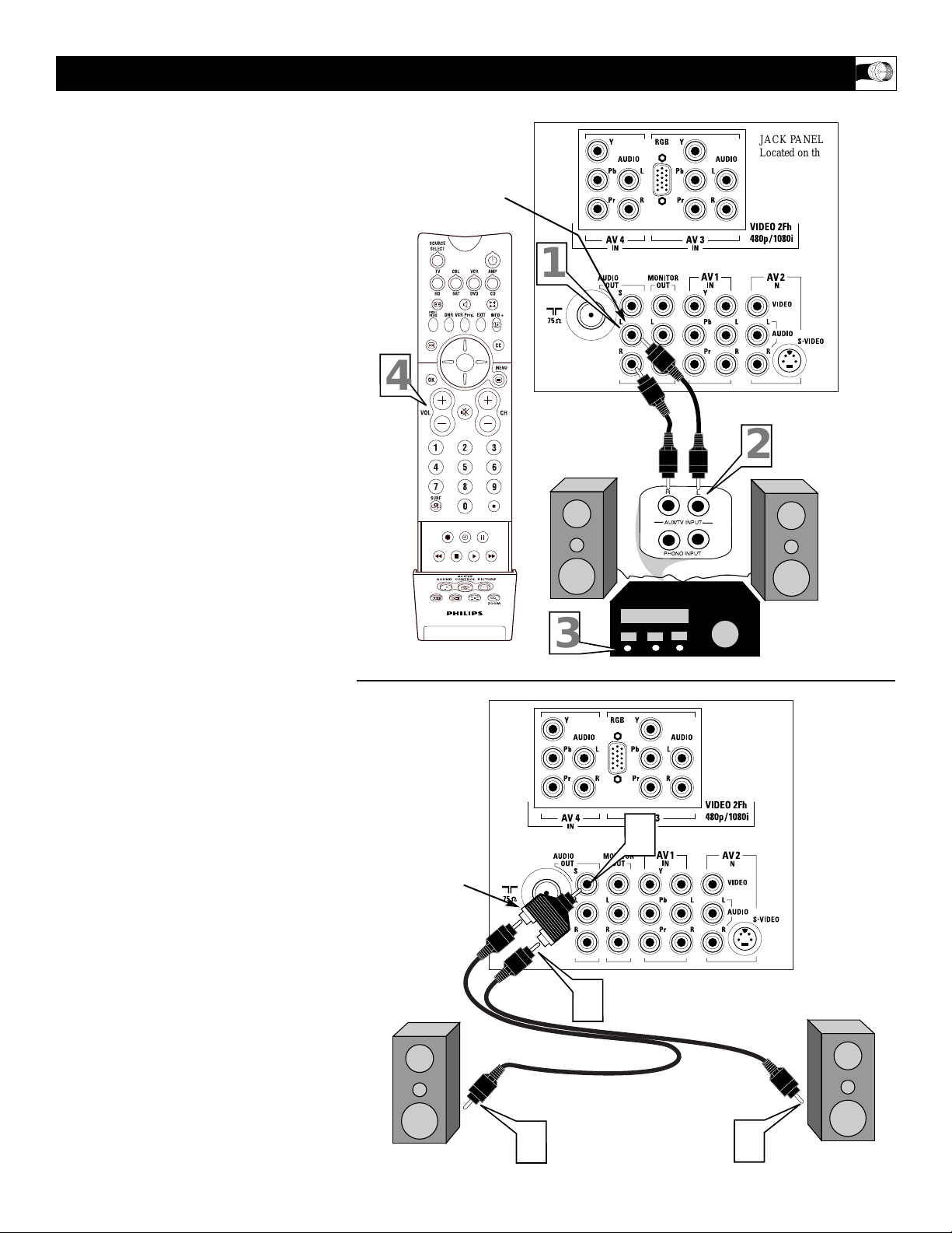
T
he Audio Output jacks are great for con-
necting to an external audio system or a
set of external speakers. This will enhance the
sound coming from the television to improve
your viewing and listening experience.
For Audio System Connection:
1
Connect one end of the R(ight) and
L(eft) Audio Cables (red and white)
to the AUDIO OUT (Left and Right)
jacks on the television.
2
Connect the other ends of the R(ight)
and L(eft) Audio Cables (red and
white) to the Audio Left and Right
Input jacks on the external Audio
System.
3
Turn the Audio System and the TV
on. Adjust the volume coming from
the Audio System to a pleasant listening level.
4
You can now adjust the sound level
coming from the audio system by
pressing the VOLUME (+) or (–)
button on the TV or remote control.
For External Speaker Connection:
1
Connect one end of the R(ight) and
L(eft) Audio Cables (red and white)
to each of the external speakers.
2
Using a Stereo to Mono adapter (not
supplied) connect the other ends of
the Audio Cables to the Stereo end of
the adapter.
3
Connect the mono end of the Stereo
to Mono Adapter to the AUDIO OUT
S jack.
These speakers can now be adjusted using the
Speaker controls within the Setting section of
the onscreen menu. Please see page 42 for
more details.
USING THE A
UDIO OUTPUT JACKS
JACK PANEL
Located on the
back of the TV
AUDIO CABLES
(Red & White)
EXTERNAL
AUDIO SYSTEM
AUDIO OUT
L(eft) and R(ight)
JACK PANEL
Located on the
back of the TV
AUDIO CABLES
(Red & White)
EXTERNAL SPEAKER
EXTERNAL SPEAKER
STEREO TOMONO
ADAPTER
(not supplied)
External
Audio System:
External
Speakers:
4
ACITVE
CONTROL
SOUND PICTURE
1
2
R
L
AUX/TV INPUT
PHONO INPUT
ZOOM
3
2
3
1
1
16
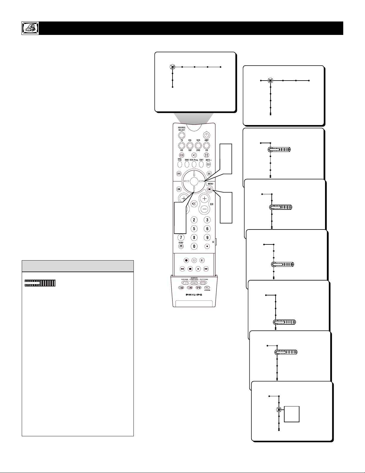
T
o adjust your TV picture controls, select a
channel and follow these steps.
1
Press the MENU button on the remote
control to show the onscreen menu.
2
Press the CURSOR RIGHT button to
highlight PICTURE.
3
Press the CURSOR DOWN button to
select one of the picture adjustment:
CONTRAST, BRIGHTNESS, COLOR,
SHARPNESS, TINT, OR COLOR TEMPERATURE.
NOTE: The menu will show only four items at a
time, so you will need to continue scrolling with
the CURSOR DOWN button to adjust the TINT
and COLOR TEMPERATURE.
4
Press the CURSOR LEFT or CURSOR
RIGHT button to adjust the selected con-
trol. OR, if COLOR TEMPERATURE is
chosen, press the CURSOR RIGHT to
choose from a submenu of options; NORMAL, COOL, or WARM.
5
Press the MENU button when finished
to remove the onscreen menu from the TV
screen.
ADJUSTING THE P
ICTURE CONTROLS
Remember, when the bar scale is centered
, the control settings are at nor-
mal, mid-range levels.
NOTE: The SHARPNESS and TINT
Controls will not be available for adjustments when tuned to the AV3/AV4/CVI
Inputs.
BRIGHTNESS – adds or subtracts light
from the darkest part of the picture.
COLOR – adds or eliminates color.
PICTURE – improves the detail of the light-
est parts of the picture.
SHARPNESS – improves the detail in the
picture.
TINT – adjusts the picture to obtain natural
skin tones.
COLOR TEMP offers NORMAL, COOL, or
WARM picture preferences.
NORMAL – keeps whites, white.
COOL – makes whites, bluish.
WARM – makes whites, reddish.
HELPFUL HINT
Settings
Demo
Install
Picture Sound Features Channels
TV
3
5
ACITVE
CONTROL
SOUND PICTURE
ZOOM
2
4
1
5
Picture Sound Features Channels
TV
Contrast
Brightness
Color
Sharpness
Picture
TV
Contrast
Brightness
Color
Sharpness
Picture
TV
Contrast
Brightness
Color
Sharpness
Picture
TV
Contrast
Brightness
Color
Sharpness
Picture
TV
Contrast
Brightness
Color
Sharpness
Picture
TV
Tint
Color Temperature
Digital processing
Dynamic contrast
Picture
TV
Tint
Color Temperature
Digital processing
Dynamic contrast
Normal
Cool
Warm
40
40
40
40
40
17
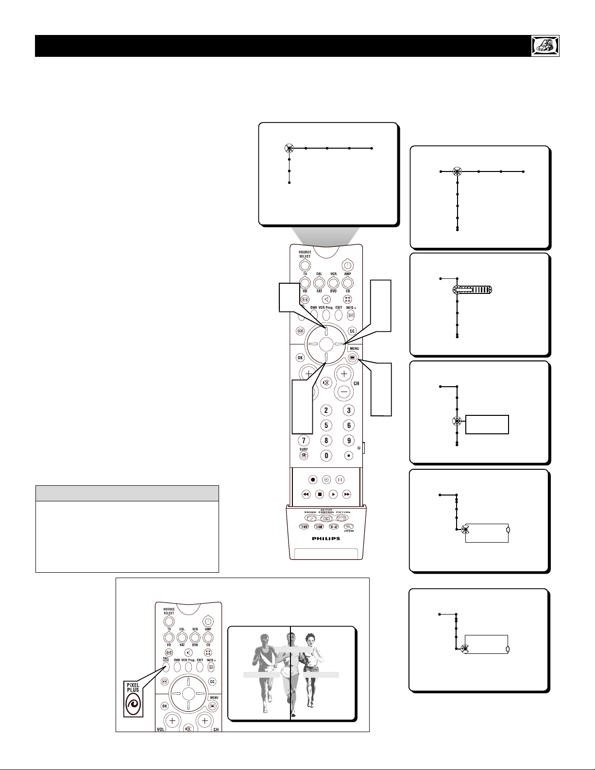
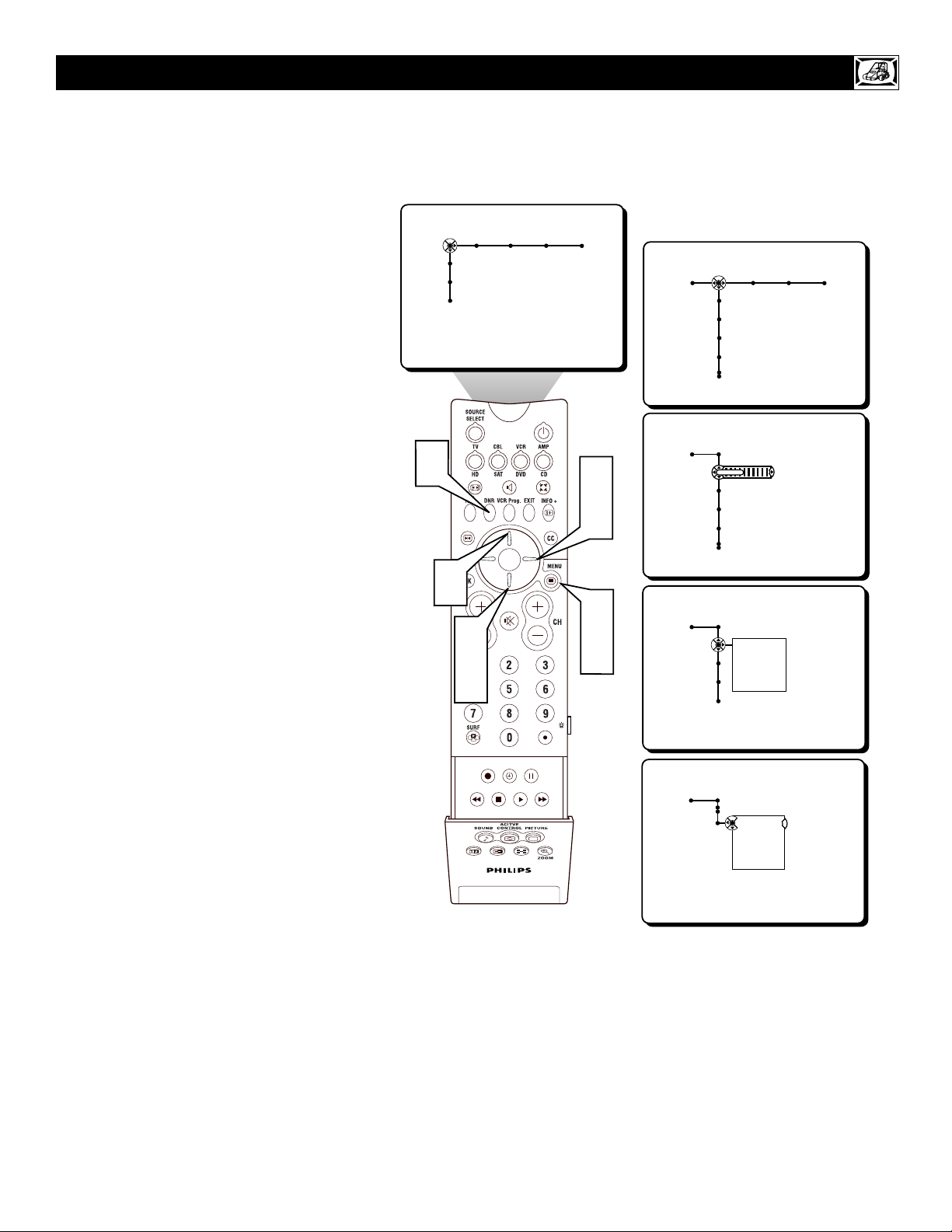
T
he Digital Processing control gives you a
choice between two different picture scan-
ning modes: Progressive Scan or Pixel Plus.
Progressive Scan doubles the number of pic-
ture lines, eliminating line flicker and providing a jitter-free picture.
Pixel Plus improves the picture quality and
appearance of onscreen images. The number
of picture lines are increased along with the
number of pixels per line, giving normal
broadcast signals, DVD reproduction or
Digital TV signals, unparalleled sharpness
and depth. This gives the viewer near High
Definition and natural looking detail without
the High Definition signal.
1
Press the MENU button on the
remote to display the onscreen menu
.
2
Press the CURSOR RIGHT button to
highlight PICTURE.
3
Press the CURSOR DOWN button
repeatedly until the DIGITAL PROCESSING control is highlighted.
4
Press the CURSOR RIGHT button
to enter the Digital Processing submenu.
5
Press the CURSOR UP or DOWN
button to select PROGRESSIVE
SCAN or PIXEL PLUS.
6
Press the MENU button to remove the
onscreen menu from the TV screen.
HOW TO
USE THE DIGITAL PROCESSING CONTROL
With the use of Pixel Plus some DVD players
may display certain screen elements or artifacts while in playback. The Auto PictureSOFT control (see page 21) can also be used
to help reduce the appearance and level of
such a screen playback condition.
HELPFUL HINT
Pixel Plus Demo
With Pixel Plus ON, there is a sharper
image with more natural motion. The
picture will appear flicker free.
Note: The Digital Processing Control is
not available for use with the AV 3 or AV 4
input jacks.
Picture Sound Features Channels
TV
Settings
Demo
Install
5
2
4
Picture Sound Features Channels
TV
Contrast
Brightness
Color
Sharpness
Picture
TV
Contrast
Brightness
Color
Sharpness
40
3
5
ACITVE
CONTROL
SOUND PICTURE
ZOOM
Pixel Plus Demo
1
6
TV
Color Temperature
Digital processing
Dynamic contrast
TV
Digital processing
TV
Digital processing
Picture
Tint
Progresive Scan
Pixel Plus
Picture
Progresive Scan
Pixel Plus
OR
Picture
Progresive Scan
Pixel Plus
Pixel Plus Off Pixel Plus On
18
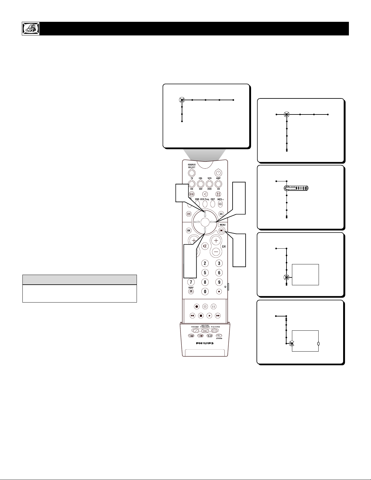
T
he Dynamic Contrast control allows you
to sharpen the picture quality by making
dark portions of the picture darker and light
portions of the picture more noticeable.
Normally, you will probably want to select
MEDIUM. In certain circumstances, however,
you may prefer MINIMUM or MAXIMUM.
1
Press the MENU button on the
remote to display the onscreen menu.
2
Press the CURSOR RIGHT button
to highlight PICTURE.
3
Press the CURSOR DOWN button
repeatedly until the DYNAMIC CONTRAST control is highlighted.
4
Press the CURSOR RIGHT button
to enter the Dynamic Contrast submenu.
5
Press the CURSOR UP or DOWN
button to select one of the Dynamic
Contrast options; OFF, MINIMUM,
MEDIUM, or MAXIMUM.
6
Press the MENU button to remove
the onscreen menu from the TV screen.
HOW TO
SET THE DYNAMIC CONTRAST CONTROL
The Dynamic Contrast control is not available for use with the AV 3 or AV 4 Inputs.
HELPFUL HINT
Picture Sound Features Channels
TV
Settings
Demo
Install
Picture Sound Features Channels
TV
Contrast
Brightness
Color
Sharpness
5
3
5
SOUND PICTURE
ACITVE
CONTROL
ZOOM
2
4
1
6
TV
Contrast
Brightness
Sharpness
TV
Color Temperature
Digital processing
Dynamic contrast
TV
Dynamic contrast
Picture
40
Color
Picture
Tint
Off
Minimum
Medium
Maximum
Picture
Off
Minimum
Medium
Maximum
19
D
ue to many reasons, such as poor cable
reception, the picture can sometimes
appear slightly ÒspeckledÓ (an indication of
signal noise in the picture). The DNR
(Dynamic Noise Reduction) control can help
eliminate this type of interference and
improve the quality of the picture.
1
Press the MENU button on the
remote to display the onscreen menu.
2
Press the CURSOR RIGHT button
to highlight PICTURE.
3
Press the CURSOR DOWN button
repeatedly until the DNR control is
highlighted.
4
Press the CURSOR RIGHT button
to enter the DNR sub-menu.
5
Press the CURSOR UP or DOWN
button to select one of the DNR
options; OFF, MINIMUM, MEDIUM,
or MAXIMUM.
6
Press the MENU button to remove
the onscreen menu from the TV screen.
7
The DNR Control can also be accessed
by simply pressing the DNR button
on the remote control.
HOW TO USE THE DNR (DYNAMIC NOISE REDUCTION) CONTROL
Settings
Picture Sound Features Channels
TV
Demo
Install
TV
Contrast
Brightness
Color
Sharpness
Picture Sound Features Channels
7
5
3
5
SOUND PICTURE
ACITVE
CONTROL
ZOOM
2
4
1
6
TV
Contrast
Brightness
Sharpness
TV
Color enhancement
Auto picture
Picture format
TV
Color
DNR
DNR
Picture
40
Picture
Off
Minimum
Medium
Maximum
Picture
Off
Minimum
Medium
Maximum
 Loading...