

Philips 34PT4323/71R User Manual

Colour Television
Operating Instructions
29PT432329PT4323
29PT4323
34PT432334PT4323
34PT4323
1-4_34PT4323/71/E 05/28/03, 10:28 AM1

TABLE OF CONTENTS
Introduction
Safety Information/Useful Tips .................................................................................................. 3
Before Calling Service ................................................................................................................. 4
Basic Installation/Functions
Hooking Up Your TV (Basic Connection) ............................................................................... 5
Use/Care of remote Control .................................................................................................... 5
Connecting the Audio/Video Sockets (Playback) .................................................................. 6
Connecting the Audio/Video Sockets (Recording) ............................................................... 8
Functions of Remote Control ................................................................................................... 9
Functions of TV Controls ...........................................................................................................11
TV Installation
Selecting the Menu Language...................................................................................................... 12
Select Tuner Mode ........................................................................................................................ 13
Automatic Tuning of Channels .................................................................................................. 14
Editing of Channels ...................................................................................................................... 15
Fine Tuning Of Channels ............................................................................................................. 16
Naming of Channels...................................................................................................................... 17
Features
Adjusting the TV Picture ............................................................................................................. 18
Adjusting the TV Sound .............................................................................................................. 19
Using the Timer.............................................................................................................................. 20
Using the Rotation feature (for certain models only)...........................................................22
Using the Screen Format ............................................................................................................ 23
Activating the Signal Strength Indicator................................................................................... 24
Using the Active Control............................................................................................................. 25
Smart Picture Control .................................................................................................................26
Smart Sound Control....................................................................................................................27
Personal Zapping ...........................................................................................................................28
General
Specifications...................................................................................................................................29
Recycling Directive – To minimise harm to the environment, the batteries
supplied with the TV set do not contain mercury or nickel cadmium. If possible,
when disposing of batteries, use recycling means available to you. Your TV set uses
materials which are reusable or which can be recycled. To minimise the amount of
waste in the environment, specialist companies recover used sets for dismantling and
collection of reusable materials (contact your dealer).
2
1-4_34PT4323/71/E 05/30/03, 9:05 AM2

SAFETY INFORMATION AND USEFUL T IPS
Safety Information
• Disconnect mains plug when :
– the red light below the TV screen is flashing continuously.
–a bright white line is displayed across the screen.
– cleaning the TV screen. Never use abrasive cleaning agents. Use a slight damp chamois
leather or soft cloth.
– there is a lightning storm.
– the set is left unattended for a prolonged period of time.
• No naked flame sources, such as lighted candles, should be placed on top of the TV or
in the vicinity.
• Do not place your TV set under direct sunlight or heat.
• Leave at least 5 cm around each side of TV set to allow for proper ventilation.
• Avoid placing your set (e.g. near the window) where it is likely to be exposed to rain
or water.
• No objects filled with liquids should be placed on top the TV so as to avoid dripping
or splashing of liquids on the set.
Useful Tips
• Do not leave your set on standby mode for a prolonged period of time. Switch off set
to allow it to be demagnetised. A demagnetised set supports good picture quality.
• Do not shift or move the set around when it is switched on. Uneveness in colour in
some parts of the screen may occur.
•Never attempt to repair a defective TV yourself. Always consult a skilled service
personnel.
3
1-4_34PT4323/71/E 04/15/03, 4:02 PM3
BEFORE CALLING SERVICE
Below is a list of frequently occurred symptoms. Before you call for service, make these simple
checks. Some of these symptoms can easily be rectified if you know what to do.
Symptom What you should do
Colour patch • Switch off the TV by the mains power button. Wait for 20
(uneveness) minutes before switching on again.
• Check the TV is not placed too near speakers or magnetic
objects.
No power • Check the TV’s AC power cord is plugged into the mains
socket. If there is still no power, disconnect plug. Wait for
60 seconds and re-insert plug. Switch on the TV again.
No picture • Check the antenna connection at the rear of the TV.
•Possible TV station problem. Try another channel.
Good picture • Try increasing the volume.
but no sound • Check that the sound is not muted. If it is muted, press the
Mute button on the remote control to restore sound.
Good sound but poor • Try increasing the contrast and brightness setting.
colour or no picture
Snowish picture and • Check antenna connection at the rear of the TV.
noise
Horizontal dotted lines • Possible electrical interference e.g. hairdryer, vacuum
cleaner, etc. Switch off appliances.
Double images or • Possible poor positioning of antenna. Using a highly
“Ghost” images directional antenna may improve reception.
TV not responding to • Check life span of batteries of remote control handset.
remote control handset • Aim remote control handset directly at remote control
sensor lens on the TV.
4
1-4_34PT4323/71/E 04/15/03, 4:02 PM4
HOOKING UP Y OUR TV (BASIC CONNECTION)
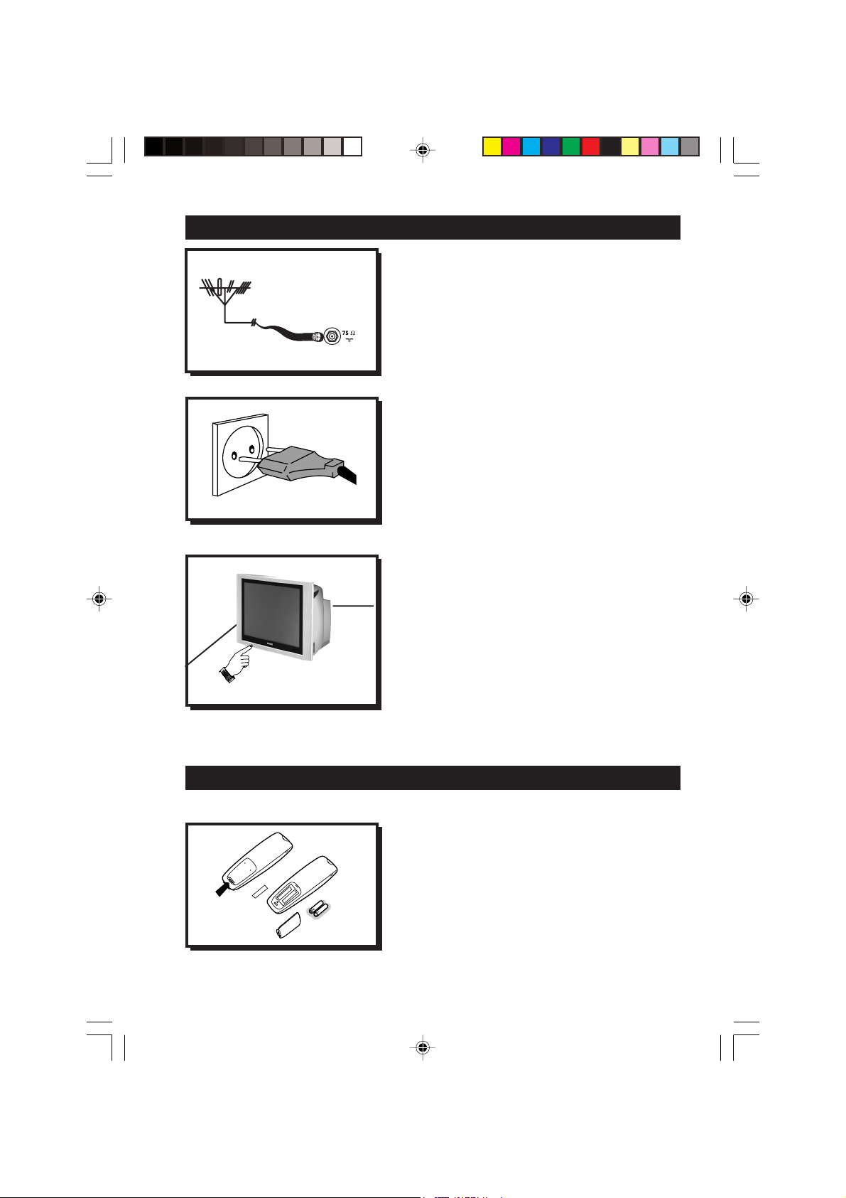
Antenna Connection
• Connect the aerial plug to the antenna socket
on the backcover.
• Insert the mains plug into the wall socket.
Mains Connection
•For correct mains voltage, refer to type sticker at
the rear of the TV set
• Consult your dealer if mains supply is different.
Note : This diagram is not representative of the
actual plug and socket.
Switching on the Set
•Press the main power button to switch on/
off the TV.
• If the set is on standby (indicator is red),
press the Power button on the remote
control to switch on set.
¬¬
¬
¬¬
USE/CARE OF REMOTE CONTROL
5-11_34PT4323/71/E 04/15/03, 11:02 AM5
• Insert the correct type of batteries into the
compartment.
• Ensure the batteries are placed in the right
direction.
5

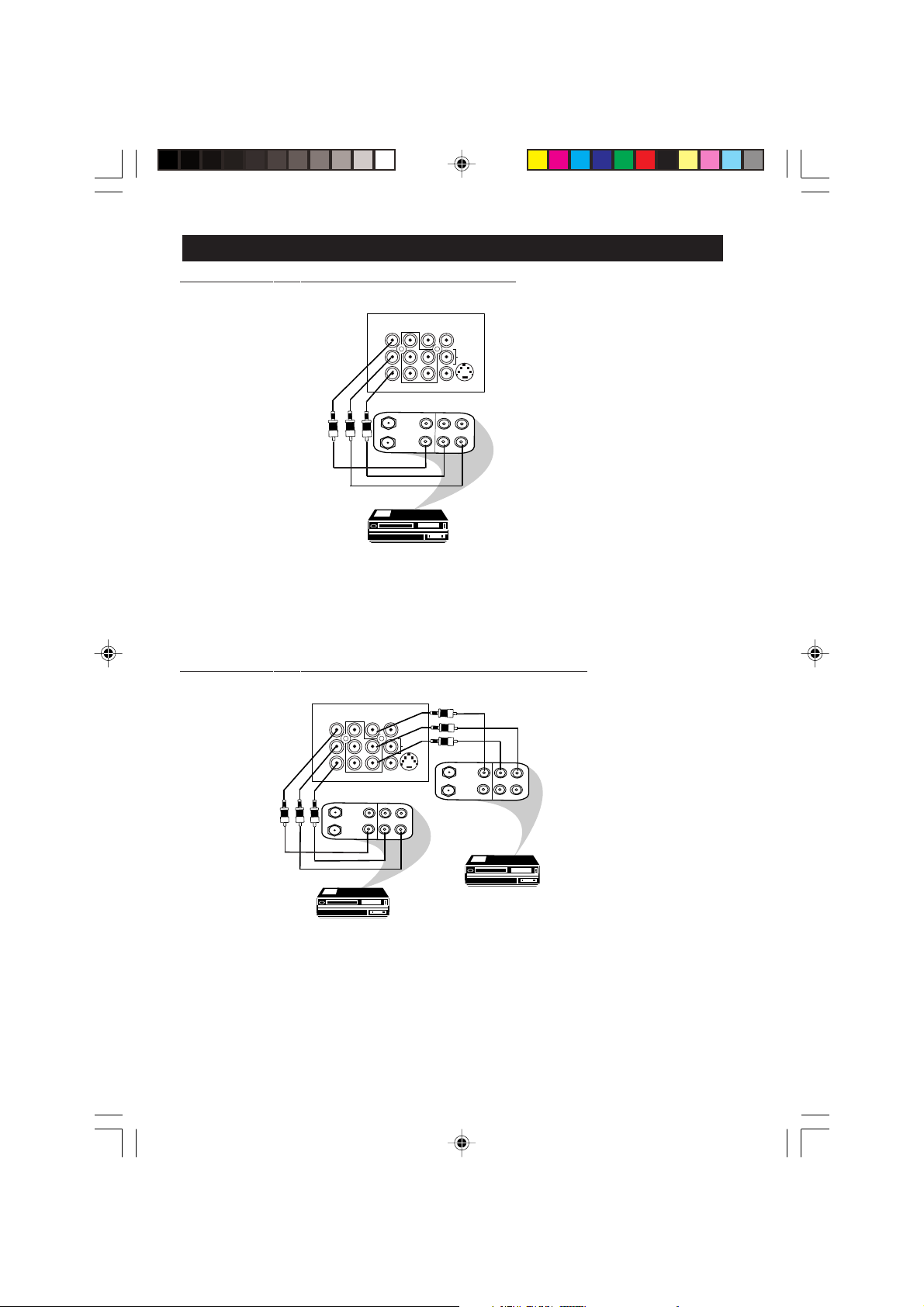
CONNECTING THE AUDIO/VIDEO SOCKETS (PLAYBACK)
COMPONENT VIDEO INPUT
OUT
ANTENNA
IN
AV1 in AV2 inMonitor out
VIDEO
Y
L
AUDIO
R
Pb
Pr
S-VIDEO
OUT
OUT
L
VIDEO
R
AUDIO
IN
IN
AV sockets on
the rear of TV
Back of VCR
VCR (equipped with Video and
Audio output sockets)
You can view the playback of VCR tapes (Video Disc players, camcorders, etc.) by using the AUDIO
and VIDEO INPUT sockets on the rear of the TV.
– Connect the VIDEO and AUDIO IN sockets on the rear of the TV to the AUDIO and
VIDEO OUT sockets on the VCR.
AV1 in AV2 inMonitor out
Y
Pb
Pr
COMPONENT VIDEO INPUT
VIDEO
L
AUDIO
R
S-VIDEO
AV sockets on
the rear of TV
Back of S-VHS VCR
OUT
AUDIO RL VIDEO
IN
OUT
OUT
OUT
S-VIDEO
ANTENNA
IN
IN
The S-Video connection on the rear of the TV is used for the playback of S-VHS VCR tapes, Video Discs,
Video Games or Compact Disc-Interactive (cd-i) discs. Better picture detail and clarity is possible with
the S-Video playback as compared to the picture from a normal antenna (RF) connection.
– Connect the S-VIDEO socket on the rear of the TV to the S-VHS OUT socket on a
S-VHS VCR.
– Connect the AUDIO IN sockets from the rear of the TV to the AUDIO OUT sockets
on the VCR. Note : You need not connect the VIDEO IN socket of the TV if S-VIDEO IN
socket is connected.
6
5-11_34PT4323/71/E 04/15/03, 11:02 AM6

CONNECTING THE A UDIO/VIDEO SOCKETS (PLACKBACK)
AV1 in AV2 inMonitor out
Y
Pb
Pr
COMPONENT VIDEO INPUT
VIDEO
L
AUDIO
R
S-VIDEO
AV sockets on rear of TV
Note: The Component Video
Input sockets (Y, Pb and Pr)
on the TV are compatible with
480i (interlaced, 1 fh) output
signals only, not 480p
(progressive scan, 2 fh)
OUT
Pb
Y
OUT
Pr
L
R
AUDIO
Back of DVD
DVD (Equipped with “Y”, “Pb” and “Pr”
and Output sockets)
You can view the playback of DVD discs by using the COMPONENT VIDEO INPUT sockets on the
rear of the TV.
– Connect the Y, Pb and the Pr INPUT sockets on the TV to the Y, P b and Pr OUTPUT
sockets on the DVD to view playback of DVD discs.
Note:
• The Y, Pb and Pr sockets on the TV are compatible with 480 i (interlaced, 1 fh) output signals
only, not 480p (progressive scan, 2 fh).
• The labels for the component video sockets may differ depending on the DVD player.
Although the abbreviations may vary, the letters B and R stand for blue and red component
signals, respectively, and Y indicates the luminance signal. Refer to the DVD player’s
instructions for use definitions and connection details.
CONNECTING THE A UDIO/VIDEO SOCKETS (PLACKBACK)
Camcorder
Connect headphone jack to
socket for personal listening
For more convenient direct playback connections, the Side Audio/Video Input sockets allow for quick
and easy connections, particularly Camcorder tape recordings.
– Connect the VIDEO socket from the Camcorder to the Side VIDEO in socket of the TV.
– Connect the AUDIO OUT sockets (Right and Left) from the Camcorder to the Side
AUDIO IN sockets.
7
5-11_34PT4323/71/E 04/15/03, 11:02 AM7
CONNECTING THE AUDIO/VIDEO SOCKETS (RECORDING)
Connection for recording from the TV channel
AV sockets on
the rear of TV
OUT
ANTENNA
IN
AV1 in AV2 inMonitor out
Y
Pb
Pr
COMPONENT VIDEO INPUT
OUT
VIDEO
IN
VIDEO
L
AUDIO
R
S-VIDEO
OUT
L
R
AUDIO
IN
VCR (equipped with Video and
Audio input sockets)
– Connect the corresponding INPUT sockets of the VCR to the MONITOR OUTPUT
sockets on the rear of the TV.
–To enhance the sound of your TV, connect the AUDIO L and R sockets to an external audio
system instead of the VCR. For mono equipment, connect only the AUDIO L socket.
Connection for recording from one VCR to another VCR
AV1 in AV2 inMonitor out
COMPONENT VIDEO INPUT
OUT
ANTENNA
IN
VIDEO
Y
L
AUDIO
R
Pb
Pr
OUT
OUT
VIDEO
R
AUDIO
IN
IN
L
S-VIDEO
ANTENNA
OUT
OUT
VIDEO
R
IN
OUT
L
AUDIO
AV sockets on
the rear of TV
Back of VCR
VCR 2
VCR 1
VCR (equipped with Video and
Audio input sockets)
– Connect the sockets of the VCR which you wish to record from, to the corresponding
sockets at either AV1 or AV2
– Connect the sockets of the receiving VCR to the MONITOR OUTPUT sockets on the
rear of the TV.
8
5-11_34PT4323/71/E 04/15/03, 11:02 AM8
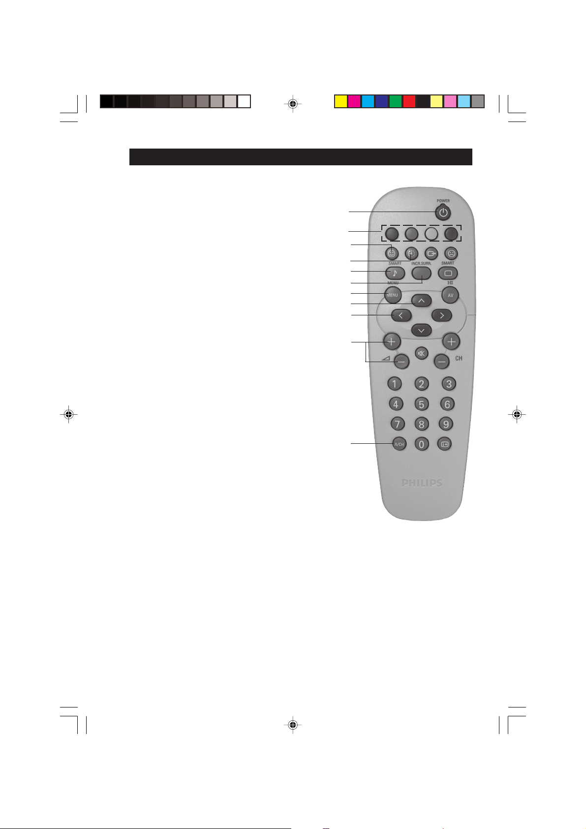
FUNCTIONS OF REMOTE CONTROL
& Power button
– Switch set off temporarily to standby mode.
(The red light indicator lights up when the set
is on standby mode).
–To switch on set from standby mode, press
Channel +/– , Digit (0 -9) or Power button.
é Personal Zapping buttons
As Personal Zapping buttons, you can surf up to
10 personal channels for each button. For detailed
description of functions, refer to section on
“Personal Zapping ”.
“ Smiley button
Allows to add and store your personal preference
channels in your Personal Preference list. For
detailed description of functions, refer to section
on “Using your Personal Zapping feature”.
‘ Sleeptimer Button
Allows you to select a time period after which the
set will switch to standby mode automatically.
( Smart Sound Button
Press the Smart Sound button repeatedly to
access 4 different types of sound settings and
choose your desired setting.
&
é
“
‘
(
§
è
!
ç
0
1
§ Incredible Surround Button
– Allows you to select Incredible Surround sound when
transmission is in stereo mode.
– Allows you to select Spatial sound when transmission
is in mono mode.
è Menu Button
Displays the main menu. Also exits menu from screen.
! Cursor Up Button
Allows you to select the next item on the menu.
ç Cursor Left Button
Allows you to select the sub-menus and adjust the
settings.
0 Volume + / – Button
Increases or decreases volume.
1 A/CH(Alternate channel) Button
Allows you to change between the current
channel and the previous channel.
5-11_34PT4323/71/E 04/15/03, 11:02 AM9
9
 Loading...