

Philips 32PT5441-37B User Manual

Color TV
Color TV
27PT5441/37
32PT5441/37
27PT6441/37
27PT6442/37
3121 235 21512
Model No
.:_______________
Serial No.:
User Manual
Thank you for choosing Philips.
Need help fast?
Read your User Manual first for quick tips that
your using your Philips product more enjoyable. If
you have read your instructions and still need
assistance you may access our online help at
www.p4c.philips.com
or
call 1-888-PHILIPS (1-888-744-5477)
while with your product.

Return your Product Registration Card today
to get the very most from your purchase.
Congratulations on your purchase, and welcome to the “family!”
Dear PHILIPS product owner:
Thank you for your confidence in PHILIPS.You’ve selected one of the best-built, bestbacked products available today.We’ll do everything in our power to keep you happy
with your purchase for many years to come.
As a member of the PHILIPS “family,” you’re entitled to protection by one of the most
comprehensive warranties and outstanding service networks in the industry.What’s
more, your purchase guarantees you’ll receive all the information and special offers for
which you qualify, plus easy access to accessories from our convenient home shopping
network.
Most importantly,you can count on our uncompromising commitment to your total
satisfaction.
All of this is our way of saying welcome - and thanks for investing in a PHILIPS product.
P.S. To get the most from your PHILIPS purchase, be sure to complete and
return your Product Registration Card at once.
Know these
safetysymbols
This “bolt of lightning” indicates uninsulated material within your unit may
cause an electrical shock. For the safety of everyone in your household,please
do not remove product covering.
The “exclamation point” calls attention to features for which you should read
the enclosed literature closely to prevent operating and maintenance problems.
WARNING: To r educe the risk of fire or electric shock, this apparatus should not
be exposed to rain or moisture and objects filled with liquids, such as vases, should
not be placed on this apparatus.
CAUTION: To prevent electric shock, match wide blade of plug to wide slot, fully
insert.
ATTENTION:Pour éviter les choc électriques, introduire la lame la plus large de la
fiche dans la borne correspondante de la prise et pousser jusqu’au fond.
Registering your model with PHILIPS makes you eligible for all of the valuable benefits
listed below, so don't miss out. Complete and return your Product Registration Card at
once to ensure:
*Proof of
Purchase
Returning the enclosed
card guarantees that your
date of purchase will be
on file, so no additional
paperwork will be
required from you to
obtain warranty service.
*Product Safety
Notification
By registering your product, you'll receive notification - directly from the
manufacturer - in the
rare case of a product
recall or safety defect.
*Additional
Benefits of Product
Ownership
Registering your product
guarantees that you'll
receive all of the privileges to which you're
entitled, including special
money-saving offers.
t
s
CAUTION
RISK OF ELECTRIC SHOCK
DO NOT OPEN
CAUTION: TO REDUCE THE RISK OF ELECTRIC SHOCK, DO NOT
REMOVE COVER (OR BACK). NO USER-SERVICEABLE PARTS
INSIDE. REFER SERVICING TO QUALIFIED SERVICE PERSONNEL.
Visit our World Wide Web Site at http://www.philips.com
IMPORTANT SAFETY INSTRUCTIONS
Read before operating equipment
1. Read these instructions.
2. Keep these instructions.
3. Heed all warnings.
4. Follow all instructions.
5. Do not use this apparatus near water.
6. Clean only with a dry cloth.
7. Do not block any of the ventilation openings.
Install in accordance with the manufacturers
instructions.
8. Do not install near any heat sources such as radia-
tors, heat registers, stoves, or other apparatus
(including amplifiers) that produce heat.
9. Do not defeat the safety purpose of the polarized
or grounding-type plug. A polarized plug has two
blades with one wider than the other. A grounding
type plug has two blades and third grounding
prong. The wide blade or third prong are provided
for your safety. If the provided plug does not fit
into your outlet, consult an electrician for replacement of the obsolete outlet.
10. Protect the power cord from being walked on or
pinched particularly at plugs, convenience receptacles, and the point where they exit from the
apparatus.
11. Only use attachments/accessories specified by the
manufacturer.
12. Use only with a cart, stand, tripod, brack-
et, or table specified by the manufacturer,
or sold with the apparatus. When a cart is
used, use caution when moving the cart/apparatus
combination to avoid injury from tip-over.
13. Unplug this apparatus during lightning storms or
when unused for long periods of time.
14. Refer all servicing to qualified service personnel.
Servicing is required when the apparatus has been
damaged in any way, such as power-supply cord
or plug is damaged, liquid has been spilled or
objects have fallen into apparatus, the apparatus
has been exposed to rain or moisture, does not
operate normally, or has been dropped.
15. This product may contain lead and mercury.
Disposal of these materials may be regulated due
to environmental considerations. For disposal or
recycling information, please contact your local
authorities or the Electronic Industries Alliance:
www.eiae.org
16. Damage Requiring Service - The appliance
should be serviced by qualified service personnel
when:
A. The power supply cord or the plug has been dam-
aged; or
B. Objects have fallen, or liquid has been spilled into
the appliance; or
C. The appliance has been exposed to rain; or
D. The appliance does not appear to operate normal-
ly or exhibits a marked change in performance; or
E. The appliance has been dropped, or the enclosure
damaged.
17. Tilt/Stability - All televisions must comply with
recommended international global safety standards for tilt and stability properties of its cabinet
design.
• Do not compromise these design standards by
applying excessive pull force to the front, or top,
of the cabinet which could ultimately overturn the
product.
• Also, do not endanger yourself, or children, by
placing electronic equipment/toys on the top of
the cabinet. Such items could unsuspectingly fall
from the top of the set and cause product damage
and/or personal injury.
18. Wall or Ceiling Mounting - The appliance
should be mounted to a wall or ceiling only as
recommended by the manufacturer.
19. Power Lines - An outdoor antenna should be
located away from power lines.
20. Outdoor Antenna Grounding - If an outside
antenna is connected to the receiver, be sure the
antenna system is grounded so as to provide some
protection against voltage surges and built up static charges.
Section 810 of the National Electric Code,
ANSI/NFPANo. 70-1984, provides information
with respect to proper grounding of the mast and
supporting structure, grounding of the lead-in wire
to an antenna discharge unit, size of grounding connectors, location of antenna-discharge unit, connection to grounding electrodes, and requirements for
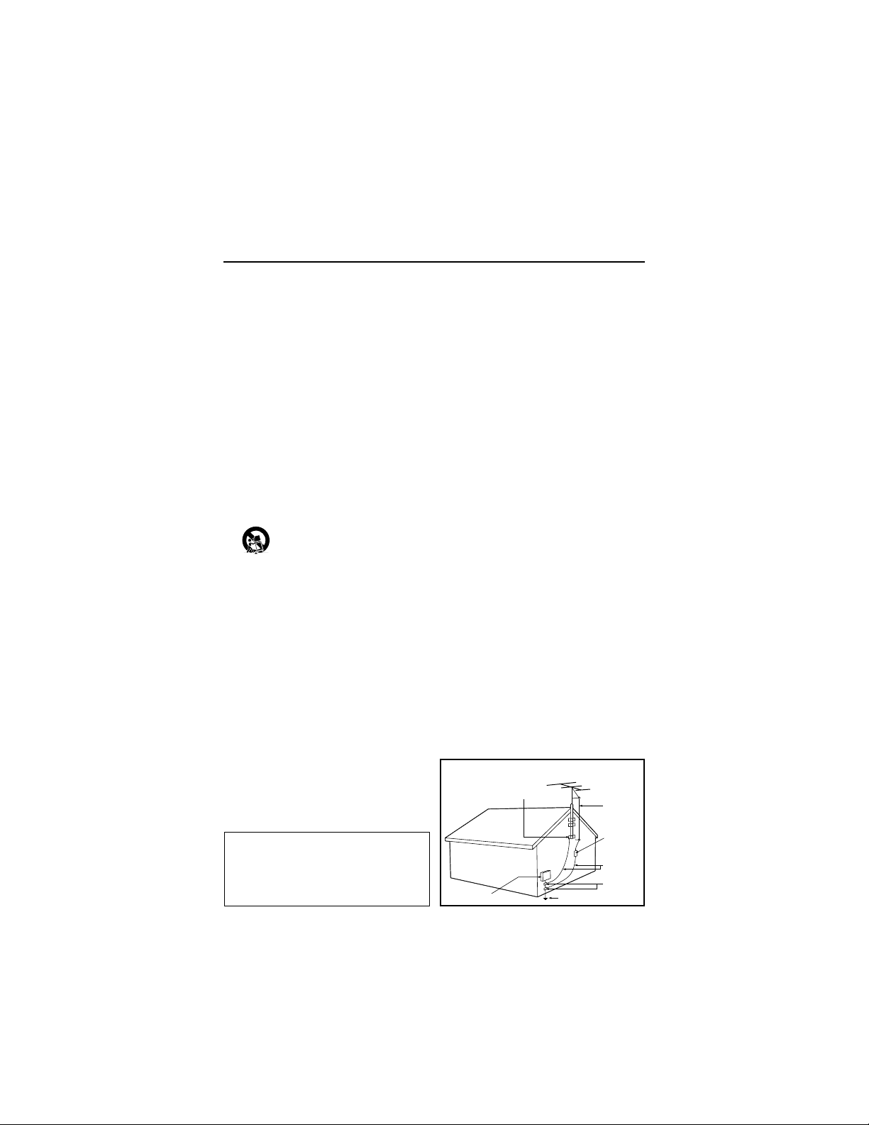
the grounding electrode. See Figure below.
21. Object and Liquid Entry - Care should be taken
so that objects do not fall and liquids are not
spilled into the enclosure through openings.
a) Warning: To reduce the risk of fire or electric
shock, this apparatus should not be exposed to rain
or moisture and objects filled with liquids, such as
vases, should not be placed on this apparatus.
22. Battery Usage CAUTION - To prevent battery
leakage that may result in bodily injury, property
damage, or damage to the unit:
• Install all batteries correctly, with + and aligned as marked on the unit.
• Do not mix batteries (old and new or carbon and
alkaline, etc.).
• Remove batteries when the unit is not used for a
long time.
Note to the CATV system installer: This
reminder is provided to call the CATV system
installer's attention to Article 820-40 of the NEC
that provides guidelines for proper grounding and,
in particular, specifies that the cable ground shall be
connected to the grounding system of the building,
as close to the point of cable entry as practical.
Example of Antenna Grounding as per
NEC - National Electric Code
ELECTRIC SERVICE EQUIPMENT
GROUND CLAMP
POWER SERVICE GROUNDING
ELECTRODE SYSTEM
(NEC ART 250, PART H)
ANTENNA LEAD
IN WIRE
ANTENNA
DISCHARGE
UNIT
(NEC SECTION 810-20)
GROUNDING
CONDUCTORS
(NEC SECTION 810-21)
GROUND CLAMPS
Side 1
PANEL LAYOUT
PANEL INDEX
Subject Panel No.
Active Control . . . . . . . . . . . . . . . . .23
Antenna/Cable Basic Connection . . .1
Audio/Video Connections
AV1 Input Jacks . . . . . . . . . . . . . . .4
Component Video Input Jacks . . . .7
Headphone Jack . . . . . . . . . . . . . . .5
Monitor Output Jacks . . . . . . . . . . .8
S-Video Input Jacks . . . . . . . . . . . .6
Side AV Input Jacks . . . . . . . . . . . .5
AutoLock™ Controls
Access Code . . . . . . . . . . . . . . . . .25
Block All Channels . . . . . . . . . . . .27
Block Channels . . . . . . . . . . . . . . .26
Clear All Blocked Channels . . . . .27
Movie Ratings . . . . . . . . . . . . . . . .28
Other Blocking Options . . . . . . . .30
TV Ratings . . . . . . . . . . . . . . . . . .29
Understanding AutoLock™ . . . . .24
Automatically Programming TV . .13
AutoPicture™ Control . . . . . . . . . .32
AutoSound™ Control . . . . . . . . . . .32
Basic Remote Operation . . . . . . . . . .3
Basic Television Operation . . . . . . . .3
Subject Panel No.
Cable Box Connection . . . . . . . . . . .2
Care and Cleaning . . . . . . . . . . . . . .36
Channel Edit . . . . . . . . . . . . . . . . . .14
Clock Controls
Activate Control . . . . . . . . . . . . . .21
Clock . . . . . . . . . . . . . . . . . . . . . . .18
Display Control . . . . . . . . . . . . . . .22
Specific Channel . . . . . . . . . . . . . .20
Start or Stop Time . . . . . . . . . . . . .19
Closed Caption Control . . . . . . . . . .31
Demo Mode . . . . . . . . . . . . . . . . . . .30
Format Control . . . . . . . . . . . . . . . .17
Language Controls . . . . . . . . . . . . .11
Limited Warranty . . . . . . . . . . . . . .41
Picture Menu Controls . . . . . . . . . .15
QuadraSurf™ . . . . . . . . . . . . . . .33-34
Remote Batteries . . . . . . . . . . . . . . . .3
Remote Button Descriptions . . . .9-10
Sleeptimer . . . . . . . . . . . . . . . . . . . .31
Sound Menu Controls . . . . . . . . . . .16
Troubleshooting . . . . . . . . . . . . . . .35
Tuner Mode . . . . . . . . . . . . . . . . . . .12
Active Control, AutoPicture, AutoSound, and Incredible Surround are trademarks of Philips
Consumer Electronics Company. Copyright 2001 Philips Consumer Electronics.*Manufactured
under license from Dolby Laboratories. “Dolby” and the double-D symbol are trademarks of Dolby
Laboratories.
MODEL
REGISTRATION
INFORMATION
PANEL
2
PANEL
3
PANEL
8
PANEL
9
PANEL
14
PANEL
15
Side 2
SAFETY
INFO
PANEL
1
LIMITED
WARRANTY
(Panel 38)
COVER
Panel Index
and
Sequence
Panel
PANEL
4
PANEL
6
PANEL
20
PANEL
22
PANEL
24
PANEL
5
PANEL
7
PANEL
21
PANEL
23
PANEL
25
PANEL
10
PANEL
12
PANEL
26
PANEL
28
PANEL
30
PANEL
11
PANEL
13
PANEL
27
PANEL
29
PANEL
31
PANEL
16
PANEL
18
PANEL
32
PANEL
34
PANEL
36
PANEL
17
PANEL
19
PANEL
33
PANEL
35
PANEL
37
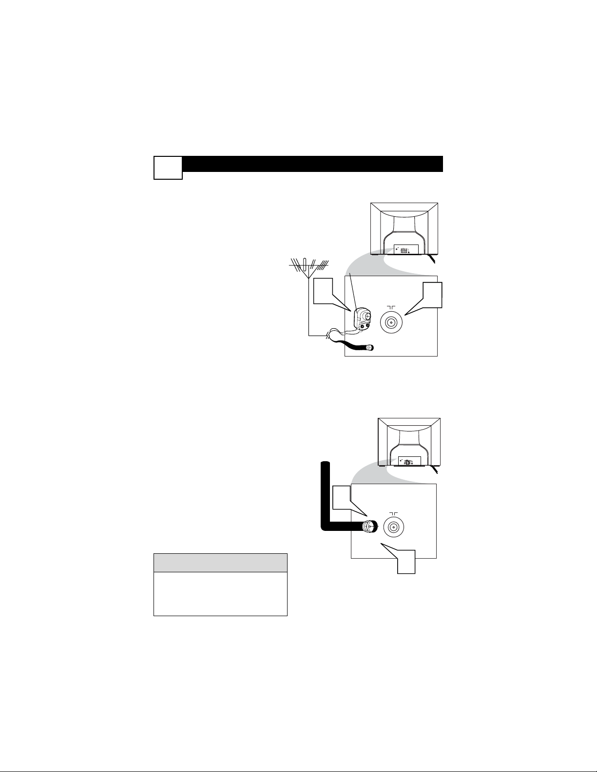
BASIC ANTENNA AND CABLE CONNECTIONS
Y
our home’s signal input might
come from a single (75 ohm)
round cable, a Converter Box, or from
an antenna. In either case the connection to the TV is very easy.
1
If your Cable TV signal or
Antenna signal is a round
cable (75 ohm) then you're
ready to connect to the TV.
If your antenna has flat twinlead wire (300 ohm), you first
need to attach the antenna wires
to the screws on a 300 to 75 ohm
adapter.
If you have a Cable Converter
Box: Connect the Cable TV sig-
nal to the Cable Signal IN(put)
plug on the Converter.
2
Connect the Cable TV cable or
Antenna cable (or 300 to 75 ohm
adapter) to the 75Ω plug on the
TV.
If you have a Cable Converter
Box: Connect the OUT(put) plug
from the Converter to the 75Ω
plug on the TV.
After using the AutoProgram Control,
press the CH + and – buttons to scroll
through all the channels stored in the
television’s memory.
HELPFUL HINT
Back of TV
Cable signal
coming from
Cable Company
Jack Panel
Back of TV
75 ⍀
1
2
ANT 75‰
L/Mono
Monitor out
VIDEO
S-VIDEO
AV1 in
Y
Pb
Pr
AV2 in
AUDIO
R
COMPONENT VIDEO INPUT
Antenna Connection
300 to 75Ω
Adapter
Combination
VHF/UHF Antenna
(Outdoor or Indoor)
Twin Lead
Wire
Round Cable
75Ω
Back of TV
Direct Cable Connection
75Ω Round
Coaxial Cable
1
1
75 ⍀
ANT 75‰
VIDEO
L/Mono
AUDIO
2
Monitor out
AV2 in
AV1 in
Y
Pb
S-VIDEO
R
Pr
COMPONENT VIDEO INPUT
TO
TV/VCR
CABLE
IN
IR
USB
DVD-D OUT
AUDIO IN
SPDIF
VIDEO
IN OUT
S-VIDEO
R L
AUDIO OUT
TV
PASSCARD
Y Pb Pr
OPTICAL
SPDIF
4
24
ANT 75‰
L/Mono
Monitor out
VIDEO
S-VIDEO
AV1 in
Y
Pb
Pr
AV2 in
AUDIO
R
COMPONENT VIDEO INPUT
L/Mono
Monitor out
VIDEO
S-VIDEO
AV1 in
Y
Pb
Pr
AV2 in
AUDIO
R
COMPONENT VIDEO INPUT
5
6
CABLE B
OX CONNECTIONS
2
I
f your cable signal uses a cable
box or decoder, follow the easy
steps below to complete the connection.
Cable Box (w/RF In/Outputs):
This connection will be mono.
1
Connect the Cable Company
supplied cable to
the signal
IN(put) plug on the back of the
Cable Box.
2
Using a separate round coaxial
cable, connect one end to the
OUT(put) (TO TV) plug on the
back of the Cable Box.
3
Connect the other end of the
round coaxial cable to the 75Ω
input on the back of the television. Screw it down finger tight.
NOTE: If applicable, set the OUTPUT CHANNEL SWITCH on the
back of the cable box to CH 3 or 4.
Tune the TV to the same channel and
change channels at the cable box. In
some cases, the cable box will automatically tune to either channel 3 or 4,
change channels until the picture
appears.
Cable Box (w/Audio/Video
Outputs):
This connection will supply Stereo
sound.
4
Connect the Cable Company
supplied cable to
the cable signal IN(put) plug on the back of
the Cable Box.
5
Using a RCA type Video Cable,
connect one end of the cable to
the Video (or ANT, your cable
box may be labeled differently)
Out jack on the cable box and
the other end to the AV1 Video
Input on the TV.
6
Connect one end of the Audio
Left and Right Cable to the left
and right Audio Out L & R
jacks on the cable box. Connect
the other end to the AV1 Audio L
& R Input jacks on the TV.
NOTE: Use the AV button on the TV
remote control to tune to the AV1
channel for the cable box signal. Once
tuned, change channels at the cable
box, not the television.
1
Jack Panel Back of Cable Box
Cable Signal IN from the
Cable Company
Round 75Ω
Coaxial Cable
Jack Panel Back of TV
Cable Signal IN
from the Cable
Company
Cable Box with A/V Outputs
Jack Panel Back of TV
Audio Cables
L (White) & R (Red)
Video Cable
(Yellow)
Cable Box (w/RF In/Outputs):
Cable Box (w/Audio/Video Outputs):
2
CABLE
TO
TV/VCR
DVD-D OUT
IR
IN
USB
VIDEO
AUDIO IN
SPDIF
IN OUT
R L
S-VIDEO
Y Pb Pr
AUDIO OUT
TV
PASSCARD
OPTICAL
SPDIF
3
75 ⍀
ANT 75‰
AV2 in
Monitor out
AV1 in
VIDEO
Y
L/Mono
Pb
AUDIO
S-VIDEO
R
Pr
COMPONENT VIDEO INPUT
POWER
3
+
–
VOLUME
+
–
CHANNEL
2
1
BASIC TV AND R
EMOTE CONTROL OPERATION
3
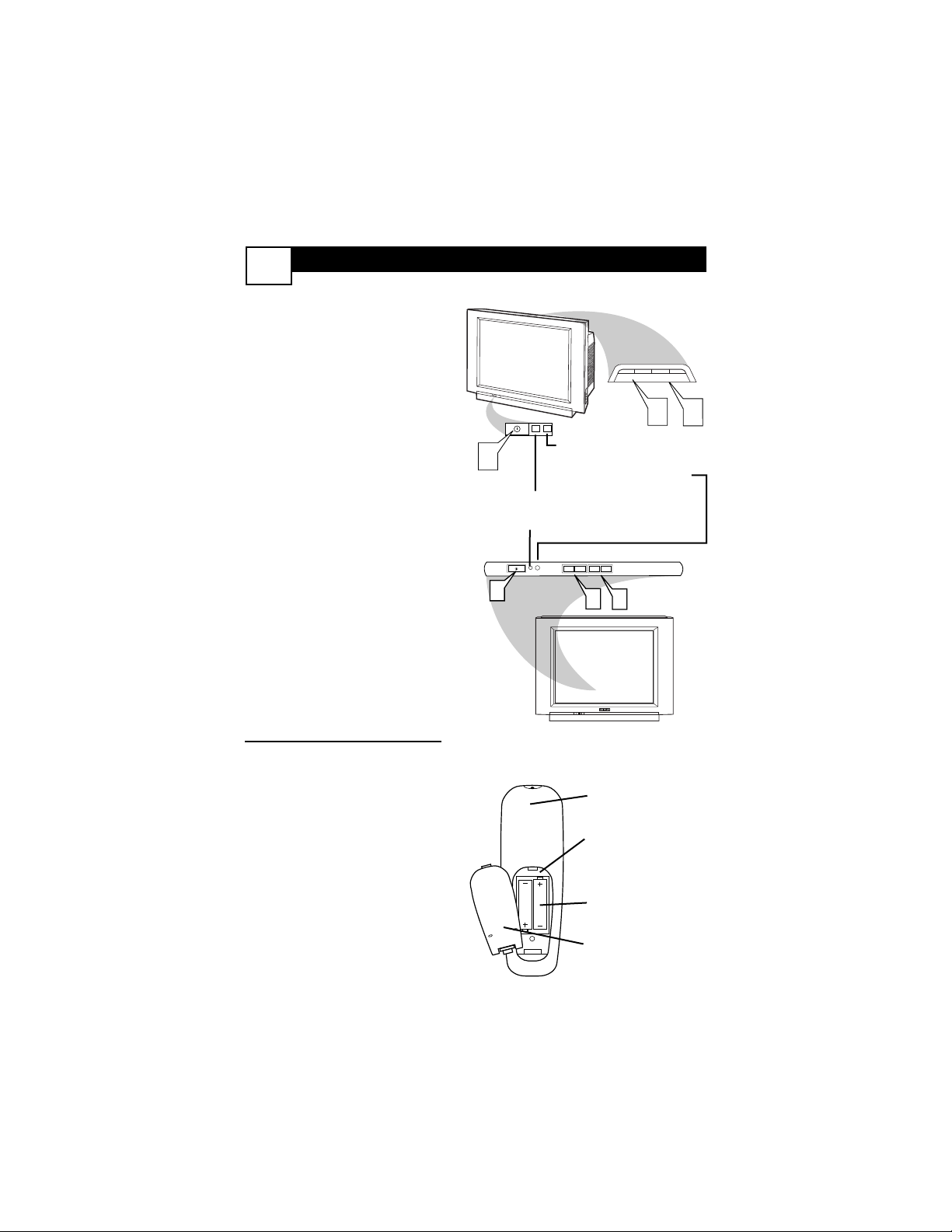
1
Press the POWER button to
turn the TV ON.
Note: You can also press any
button on the front of the TV to
turn the TV ON.
2
Press the VOLUME + button
to increase the sound level, or
the VOLUME – button to
lower the sound level.
Pressing both buttons at the
same time will display the on-
screen menu. Once in the
menu, use these buttons to
make adjustments or selections.
3
Press the CHANNEL UP + or
DOWN – button to select TV
channels.
4
Point the remote control
toward the remote sensor window on the TV when operating
the TV with the remote.
REMOTE CONTROL
T
o load the supplied batteries
into the remote:
1. Remove the battery compartment lid on the back of the remote.
2. Place the batteries (2-AA) in
the remote. Be sure the (+) and (-)
ends of the batteries line up correctly (inside of case is marked.)
3. Reattach the battery lid.
Battery Compartment
2-AA Batteries
Battery Lid
Back of Remote
3
2
1
Standby Light Indicator - Red light will show
when in the Standby Mode. Press the Power
button to return the TV to it’s active state.
Remote Sensor - Sensor for
activating remote control com-
mands when the remote is
used to control the TV.
Example of Models 27PT6441/37 and 27PT6442/37
Example of Models 27PT5441/37 and 32PT5441/37
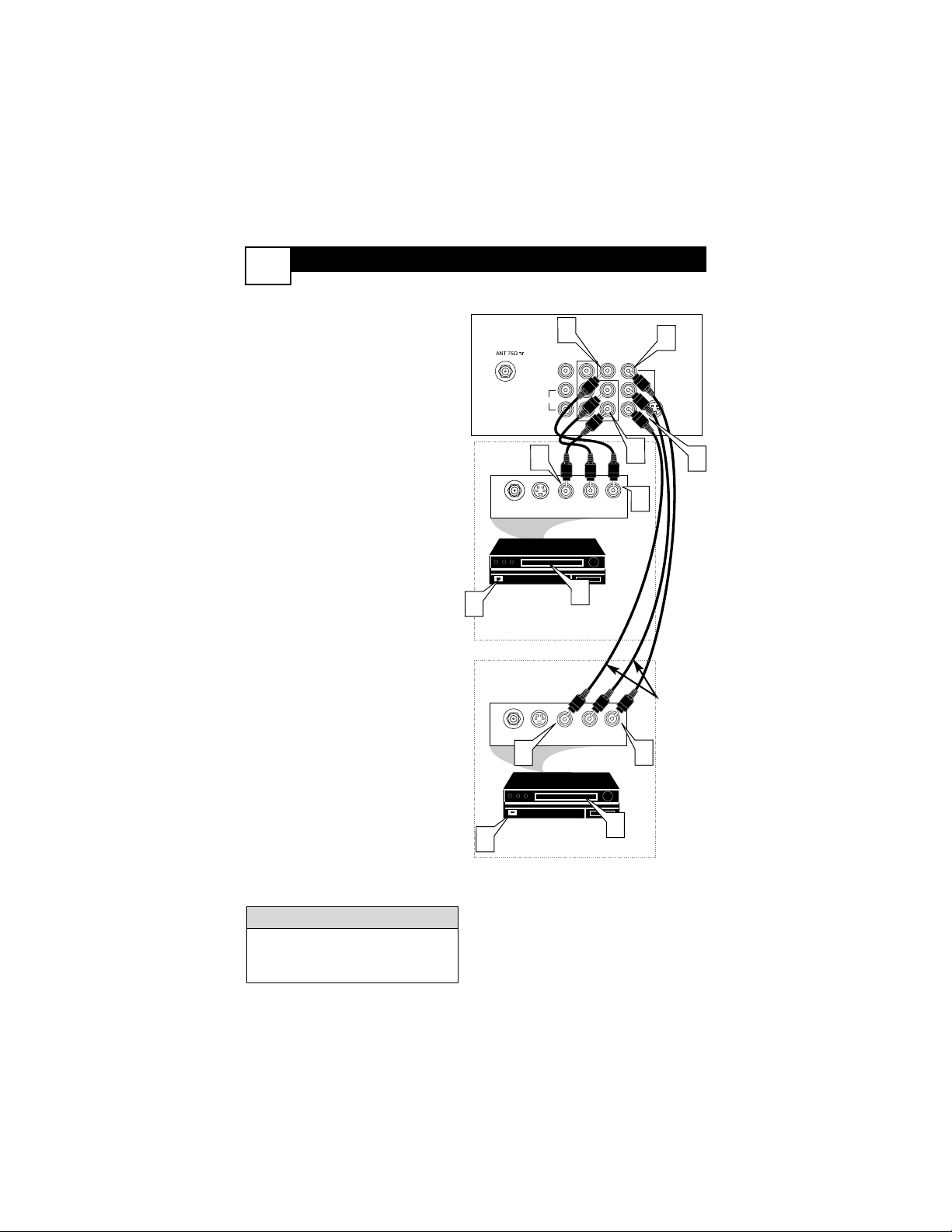
AV (AUDIO/VIDEO) INPUT C
ONNECTION
4
Monitor out
Audio and video cables are not supplied with the TV, but are available
from Philips or electronics retailers.
HELPFUL HINT
Audio In
(Red and
White)
VCR Two (or accessory
device) (Equipped with
Video and Audio Output Jacks)
Video In
(Yellow)
Back of VCR
Back of TV
AV 1
Connection
AV2 Connection
VCR One (or
accessory device) (Equipped
with Audio and Video Output
Jacks)
T
he TV’s audio/video input jacks
are for direct picture and sound
connections between the TV and a
VCR (or similar device) that has
audio/video output jacks. Both the
AV1 and AV2 Input Jack connections
are shown on this page, but either
one can be connected alone. Follow
the easy steps below to connect your
accessory device to the AV1 and AV2
IN Jacks located on the back of the
TV.
1
Connect the VIDEO (yellow)
cable to the VIDEO AV 1 IN (or
AV2 IN) jack on the back of the
TV.
2
Connect the AUDIO (red and
white) cables to the AUDIO (left
and right) AV 1 IN (or AV2 in)
jacks on the rear of the TV.
3
Connect the VIDEO (yellow)
cable to the VIDEO OUT jack on
the back of the VCR (either one
or two) or accessory device being
used.
4
Connect the AUDIO (red and
white) cables to the AUDIO (left
and right) OUT jacks on the rear
of the VCR (either one or two) or
accessory device being used.
5
Turn the VCR (either one or
two) or accessory device and
the TV ON.
6
Press the AV button to set the
TV to its AV1or AV2 channel.
7
With either of the VCRs (or
accessory devices) ON and a prerecorded tape (CD, DVD, etc.)
inserted, press the PLAY button
to view the tape on the television.
VIDEO
L/Mono
AUDIO
R
1
AV1 in
Y
Pb
Pr
COMPONENT VIDEO INPUT
AV2 in
3
S-VIDEO
5
5
ANT/CABLE
OUT
ANT/CABLE
OUT
4
2
S-VIDEO
S-VIDEO
OUT
2
R L
VIDEO
AUDIO OUT
OUT
1
OUT
4
7
R L
VIDEO
AUDIO OUT
OUT
3
7
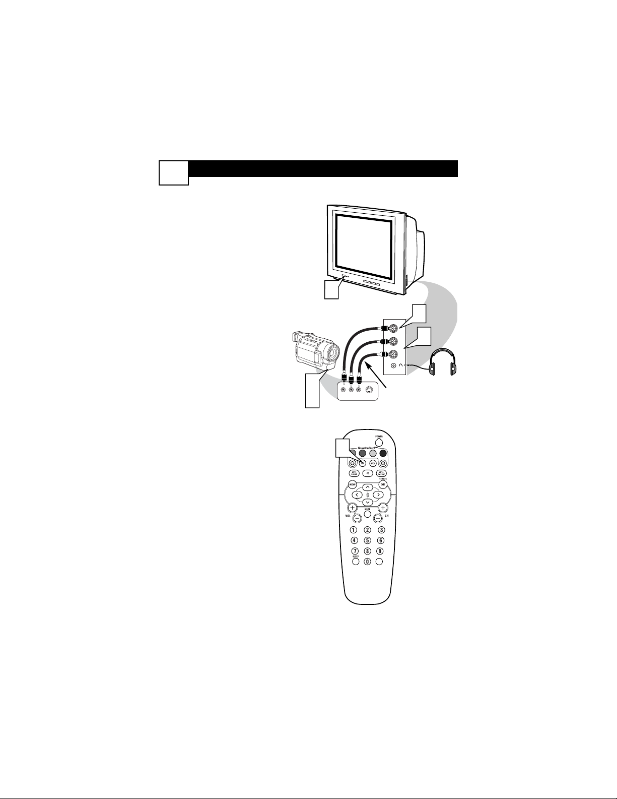
SIDE AV CONNECTIONS
5
A
udio and Video Side Inputs are
available for a quick connec-
tion of a VCR, to playback video
from a camera, or attach a gaming device. Use the AV button on
the remote control to tune these
inputs.
1
Connect the video (yellow)
cable from the Video output
on the Camera (or accessory
device) to the Video (yellow)
Input located on the SIDE of
the TV.
2
For Stereo Devices: Connect
the audio cable (red and
white) from the Audio Left
and Right Outputs on the
Camera to the Audio In
(white) jack on the SIDE of
the television.
For Mono Devices: Connect
one end of the audio cable
from the Audio Out jack on
the device to the Audio In
(white) jack on the SIDE of
the television.
3
Turn the TV and the accessory device ON.
4
Press the AV button on the
remote control to tune the TV
to the side input jacks.
“Front” will appear on the
TV screen.
5
Press the PLAY button
on the accessory device to
view playback, or to access
the accessory device (camera,
gaming unit, etc.).
Front
Side Jack panel
of TV
Audio
Cables
Video
Cable
Jack Panel of Accessory Device
Optional
Headphones
3
5
3
LEFT RIGHT
4
1
VIDEO
L
2
AUDIO
R
VIDEOAUDIO
S-VIDEO
VOL
S-VIDEO (S-VHS) I
NPUT CONNECTIONS
T
he S(uper)-Video connection on
the rear of the TV can provide
you with better picture detail and
clarity for the playback of accessory
sources such as DBS (digital broadcast satellite), DVD (digital video
discs), video games, and S-VHS VCR
(video cassette recorder) tapes than
the normal antenna picture connections.
NOTE: The accessory device must
have an S-VIDEO OUT(put) jack in
order for you to complete the connection on this page.
1
Connect one end of the SVIDEO CABLE to the S-
VIDEO jack on the back of the
TV. Then connect one end the
AUDIO (red and white)
CABLES to the AV1 in AUDIO
L and R (left and right) jacks on
the rear of the TV.
2
Connect other end of the SVIDEO CABLE to the S-VHS
(S-Video) OUT jack on the back
of the VCR. Then connect the
other ends of the AUDIO (red
and white) CABLES to the
AUDIO (left and right) OUT
jacks on the rear of the VCR.
3
Turn the VCR and the TV
ON.
4
Press the AV button or the
CH + or CH – buttons on the
remote to scroll the channels
until SVHS appears in the upper
left corner of the TV screen.
5
Now your ready to place a prerecorded video tape in the VCR
and press the PLAY button
.
VCR or External
Accessory Device
(with S-Video
Output)
Audio Cables
(Red &
White)
S-Video
Cable
Back of TV
6
Monitor out
VIDEO
L/Mono
AUDIO
R
2
AV1 in
Y
Pb
Pr
COMPONENT VIDEO INPUT
AV2 in
1
S-VIDEO
2
3
L R
AUDIO OUT
4
S-VIDEO
VIDEO
OUT
ANT/CABLE
OUT
OUT
1
5
VOL
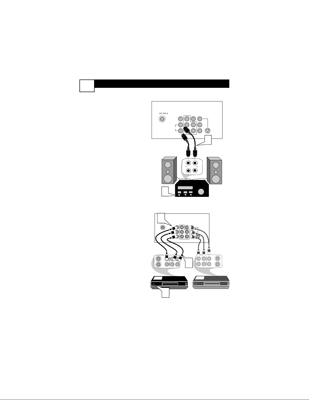
COMPONENT VIDEO (CVI) INPUT CONNECTIONS
C
omponent Video inputs provide
for the highest possible color
and picture resolution in the playback of digital signal source material, such as with DVD players. The
color difference signals (Pb, Pr) and
the luminance (Y) signal are connected and received separately,
which allows for improved color
bandwidth information (not possible
when using composite video or SVideo connections).
1
Connect the Component (Y,
Pb, Pr) Video OUT jacks from
the DVD player (or similar
device) to the (Y, Pb, Pr) in(put)
jack on the TV. When using the
Component Video Inputs, it is
best not to connect a signal to the
AV in Video Jack.
2
Connect the red and white
AUDIO CABLES to the Audio
(left and right) output jacks on
the rear of the accessory device
to the Audio (L and R) AV1 in
Input Jacks on the TV.
3
Turn the TV and the DVD (or
digital accessory device) ON.
4
Press the AV button or the
CH + or CH – buttons to
scroll the available channels
until CVI appears in the upper
left corner of the TV screen.
5
Insert a DVD disc into the
DVD player and press the
PLAY button on the DVD
Player.
The description for the component video
connectors may differ depending on the
DVD player or accessory digital source
equipment used (for example, Y, Pb, Pr; Y,
B-Y, R-Y; Y, Cr, Cb). Although abbreviations and terms may vary, the letters b and r
stand for the blue and red color component
signal connectors, and Y indicates the luminance signal. Refer to your DVD or digital
accessory owner’s manual for definitions and
connection details.
HELPFUL HINT
Component
Video Cables
(Green, Blue,
Red)
Audio
Cables
(Red &
White)
Accessory Device
Equipped with
Component Video
Outputs
Back of TV
The CVI connection will be dominate over the AV1
in Video Input. When a Component Video Device is
connected as described, it is best not to have a video
signal connected to the AV1 in Video Input jack.
7
Monitor out
VIDEO
L/Mono
Y
AUDIO
R
COMP VIDEO
COMPONENT VIDEO INPUT
1
3
AV2 in
AV1 in
2
Y
Pb
Pr
S-VIDEO
VIDEO
Pb
OUT
OUT
Pr
S-VIDEO
AUDIO
R
OUT
L
5
4
VOL
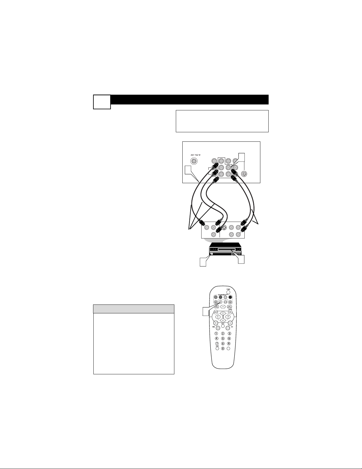
MONITOR OUT
(PUT) CONNECTIONS
8
T
he Audio/Video (Monitor) Output
jacks are great for recording with
a VCR or used to connect an external audio system for better sound
reproduction.
AUDIO SYSTEM
CONNECTION:
1
Connect one end of the
R(ight) and L(eft) AUDIO
(Monitor Out) jacks on the TV
to the R and L audio input jacks
on your amplifier or sound system. Set the audio system’s volume to a normal listening level.
2
Turn the TV and audio system ON. To adjust the volume
on the audio system, you will
need to change the volume at
the external audio system, not
the television.
SECOND VCR CONNECTION:
NOTE: Refer to panel number 4 for
the proper hookup of the first VCR.
Follow the instructions on how to
tune to the AV1 channel to view a
pre-recorded tape.
The following steps allow you to
connect a second VCR to record
the program while your watching
it.
3
Connect one end of the yellow
Video Cable to the Monitor
Out VIDEO plug. Connect the
other end to the VIDEO IN plug
on the second VCR.
4
Connect one end of the red
and white Audio cable from
the Monitor Out AUDIO L and
R plugs on the TV to the
AUDIO IN plugs on the VCR.
5
Turn the Second VCR ON,
insert a VHS tape and it’s
ready to record what’s being
viewed on the TV screen.
Monitor out
Back of TV
Audio Cables
(Red and White)
Back of TV
Audio
Cables
1st VCR
(refer to panel 4 for
proper connection)
Video
Cable
2nd VCR with Audio and
Video Input Jacks
SECOND VCR CONNECTION:
AUDIO SYSTEM CONNECTION:
VIDEO
L/Mono
AUDIO
R
AV1 in
Y
Pb
Pr
COMPONENT VIDEO INPUT
AV2 in
S-VIDEO
1
3
R
L
T
U
P
IN
V
/T
X
U
A
T
U
P
IN
O
N
O
H
P
2
AV1 in
Y
Pb
Pr
COMPONENT VIDEO INPUT
RL
4
AV2 in
S-VIDEO
ANTENNA
OUTOUT
IN
VIDEO
LR
AUDIO
ANTENNA
OUT
IN
IN
Monitor out
VIDEO
L/Mono
AUDIO
R
ANTENNA
OUT OUT
IN
AUDIO
VIDEO
ANTENNA
OUT
IN
IN
5
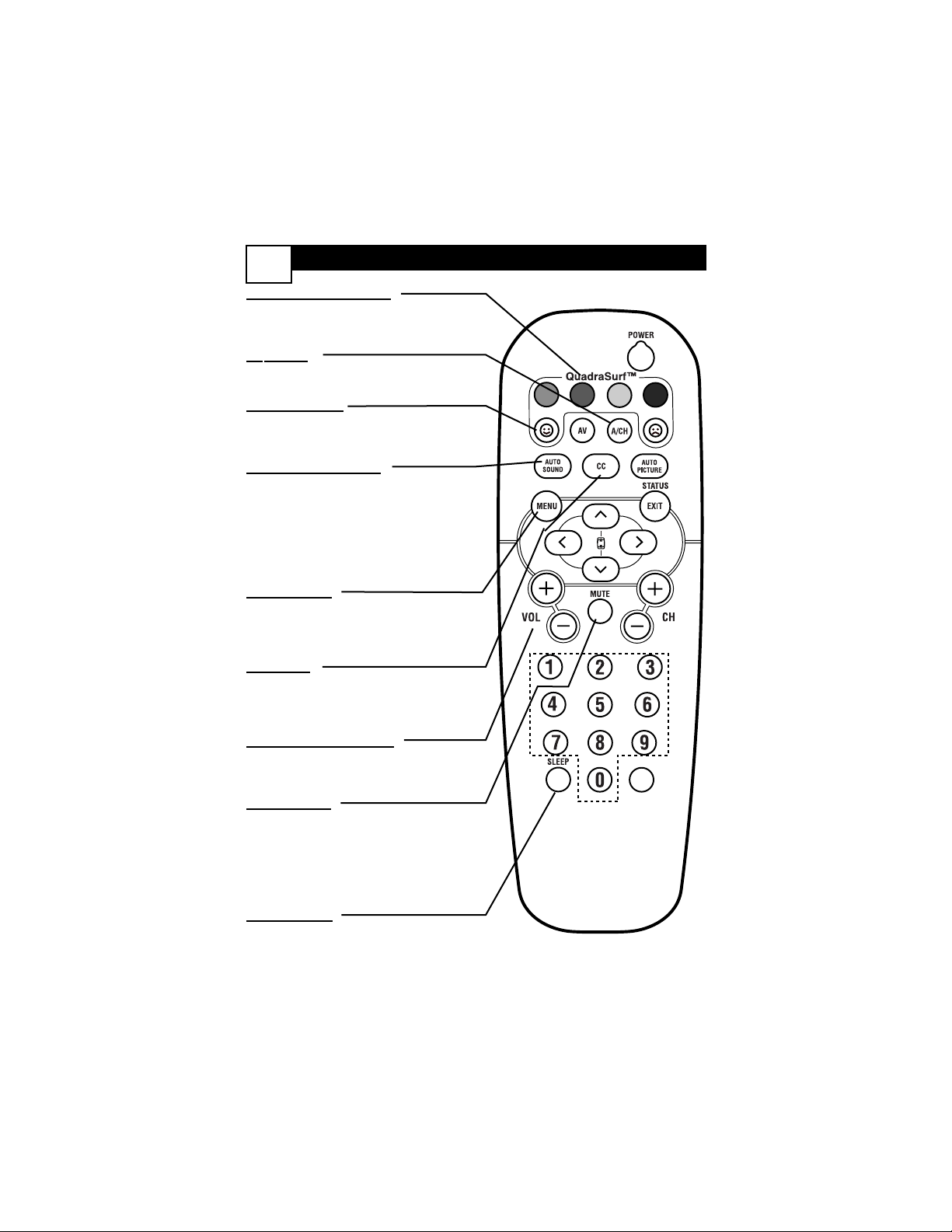
REMOTE CONTROL BUTTON
DESCRIPTIONS
9
QUADRASURF Buttons
(Red, Green, Yellow, Blue) Allows you to
store and surf up to 10 channels you
choose for each colored button.
A
V Button
Press to select an accessory signal input
from the front AV Inputs.
SMILEY
Button
Press to add channels to the
“QuadraSurf” lists. Works with all colored buttons.
AUT
O SOUND Button
Press repeatedly to choose from different
factory pre-defined sound settings.
Choose from Personal (how you set the
Sound Menu options), Voice (for programming with speaking only), Music
(for musical type programs such as concerts), or Theatre (used when watching
movies).
MENU
Button
Press to display the on-screen menu. Also
can be used to back out of the on-screen
menu until it disappears from the TV’s
screen.
CC Button
Press to activate the Closed Captioning
options. Repeatedly pressing the CC button will scroll the available options on the
TV screen.
V
OL(ume) + or - Buttons
Press the VOL + button to increase the
TV’s sound level. Press the VOL – button
to decrease the TV’s sound level.
MUTE Button
Press the mute button to eliminate the
sound being heard from the TV. “MUTE”
will be displayed on the TV’s screen.
Press again to restore the TV’s volume to
it’s previous level. pressing this button for
5 seconds will activate the Demo Mode.
(See panel 30 for more details.)
SLEEP
Button
Press the Sleep button to set the TV to
automatically turn itself off after a set
period of time. Press repeatedly to select
15, 30, 45, 60, 90, 120, 180, or 240 minutes.
VOL
 Loading...