

Page 1

TPS18.1E
EU
Chassis name Platform Model name
24PFS5603/12
24PFT5603/05
TPS18.1E LA MSD92L
24PFT5603/12
32PFS5603/12
32PFT5603/05
32PFT5603/12
Published by AMY/SC 1806 Quality Subject to modification 3122 785 20630
2018 © TP Vision Netherlands B.V.
All rights reserved. Specifications are subject to change without notice. Trademarks are the
property of Koninklijke Philips Electronics N.V. or their respective owners.
TP Vision Netherlands B.V. reserves the right to change products at any time without being obliged to adjust
earlier supplies accordingly.
PHILIPS and the PHILIPS’ Shield Emblem are used under license from Koninklijke Philips Electronics N.V.
2018-Feb-09
Page 2

1. Product information……….…………………………………………………………………………………3
2. Precautions, Notes, and Abbreviation List…………….………………………………………………5
3. Mechanical Instructions……………….………………………………………………………………….11
Cable dressing (24" 5603 series)…………….……………………………………………………………11
Cable dressing (32" 5603 series)…………….……………………………………………………………12
Assembly/Panel Removal ……………………………………………………………………………………13
4. Service Modes…………….……………….……………….…………………………………………….….18
5. Software upgrading, Error Code and Panel Code………...………………………………………..22
6. Trouble Shooting……………………………………………...……………………………………………..26
7. Electrical Diagram…..……………………….………………………………………………………………29
8. IC Data Sheet……...…………………………………………………………………………………….…..33
9. Circuit Diagrams……………...………………………………………………………………………………35
9.1 715G7734 PSU……………………………………………………………………..……………………35
9.2 715G7735 PSU……………………………………………………………………..……………………37
9.3 715G9249 SSB………………………………………………………………………..…………………38
9.4 715G8576 IR/LED Panel……………………………………………………………………………50
9.5 715G8767 IR/LED Panel……………………………………………………………………………51
9.6 715G7088 Keyboard control panel………………………………..……………………………….52
10. Styling Sheet…………….………………….……………………………………………………………..53
10.1 5603 series 24"…….………………………………………………………………………………….53
10.2 5603 series 32"……………………………………………………………………………………….54
Published by AMY/SC 1806 Quality Subject to modification 3122 785 20630
2018 © TP Vision Netherlands B.V.
All rights reserved. Specifications are subject to change without notice. Trademarks are the
property of Koninklijke Philips Electronics N.V. or their respective owners.
TP Vision Netherlands B.V. reserves the right to change products at any time without being obliged to adjust
earlier supplies accordingly.
PHILIPS and the PHILIPS’ Shield Emblem are used under license from Koninklijke Philips Electronics N.V.
2018-Feb-09
Page 3

1. Product information
Product information is subject to change without notice.
For detailed product information, please visit
www.philips.com/support
Display Type
Diagonal screen size
• 60 cm / 24 inch
• 80 cm / 32 inch
Display resolution
• 1920 x 1080
Display Input Resolution
Video formats
Resolution – Refresh rate
• 480i – 60 Hz
• 480p– 60 Hz
• 576i – 50 Hz
• 576p– 50 Hz
• 720p– 50 Hz, 60 Hz
• 1080i– 50 Hz, 60 Hz
• 1080p– 24 Hz, 25 Hz, 30 Hz
Computer formats
Resolutions (amongst others)
• 640 x 480p – 60Hz
• 800 x 600p – 60Hz
• 1024 x 768p – 60Hz
• 1280 x 768p – 60Hz
• 1360 x 768p – 60Hz
• 1280 x 1024p – 60Hz
• 1920 x 1080p – 60Hz
Connectivity
5603 (32") series TV
For 32PFS5603
TV Rear
- HDMI 1 ARC: HDMI Audio Return Channel
- HDMI 2
- DIGITAL AUDIO OUT: SPDIF
- AUDIO IN (DVI): Stereo 3.5mm mini-jack
- SCART (RGB/CVBS): SCART adaptor
- TV ANTENNA: 75 ohm coaxial (IEC)
- Satellite
TV Side
- CI: Common Interface
- USB
- Headphones: Stereo 3.5mm mini-jack
For 32PFT5603
TV Rear
- HDMI 1 ARC: HDMI Audio Return Channel
- HDMI 2
- DIGITAL AUDIO OUT: SPDIF
- AUDIO IN (DVI): Stereo 3.5mm mini-jack
- SCART (RGB/CVBS): SCART adaptor
- TV ANTENNA: 75 ohm coaxial (IEC)
- Network LAN - RJ45 (for Freeview HD)*
TV Side
- CI: Common Interface
- USB
- Headphones: Stereo 3.5mm mini-jack
* Network port is only for UK models
5603 (24") series TV
For 24PFS5603
TV Rear
- HDMI 1 ARC: HDMI Audio Return Channel
- HDMI 2
- DIGITAL AUDIO OUT: SPDIF
- VGA
- AUDIO IN (DVI/VGA): Stereo 3.5mm mini-jack
- SCART (RGB/CVBS): SCART adaptor
- TV ANTENNA: 75 ohm coaxial (IEC)
- Satellite
TV Side
- CI: Common Interface
- USB
- Headphones: Stereo 3.5mm mini-jack
For 24PFT5603
TV Rear
- HDMI 1 ARC: HDMI Audio Return Channel
- HDMI 2
- DIGITAL AUDIO OUT: SPDIF
- VGA
- AUDIO IN (DVI/VGA): Stereo 3.5mm mini-jack
- SCART (RGB/CVBS): SCART adaptor
- TV ANTENNA: 75 ohm coaxial (IEC)
- Network LAN - RJ45 (for Freeview HD)*
TV Side
- CI: Common Interface
- USB
- Headphones: Stereo 3.5mm mini-jack
Page 4

* Network port is only for UK models
* Only for DVB-T2, DVB-S2
Reception
For PxT series TV
- Aerial input : 75 ohm coaxial (IEC75)
- Tuner bands : Hyperband, S-Channel, UHF, VHF
- DVB : DVB-T2, DVB-C (cable) QAM
- Analogue video playback : SECAM, PAL
- Digital video playback : MPEG2 SD/HD (ISO/IEC
13818-2), MPEG4 SD/HD (ISO/IEC 14496-10), HEVC*
- Digital audio playback (ISO/IEC 13818-3)
* Only for DVB-T2
For PxS series TV
- Aerial input : 75 ohm coaxial (IEC75)
- Tuner bands : Hyperband, S-Channel, UHF, VHF
- DVB : DVB-T2, DVB-C (cable) QAM
- Analogue video playback : SECAM, PAL
- Digital video playback : MPEG2 SD/HD (ISO/IEC
13818-2), MPEG4 SD/HD (ISO/IEC 14496-10), HEVC*
- Digital audio playback (ISO/IEC 13818-3)
- Satellite aerial input : 75 ohm F-type
- Input frequency range : 950 to 2150MHz
- Input level range : 25 to 65 dBm
- DVB-S2 QPSK, symbol rate 2 to 45M symbols, SCPC
and MCPC
- LNB : DiSEqC 1.0, 1 to 4 LNBs supported, Polarity
selection 14/18V, Band selection 22kHz, Tone burst
mode, LNB current 300mA max
Sound
• Output power (RMS) :
24” series: 6W
32” series: 16W
• Dolby Audio
• DTS 2.0+ Digital out ™
Multimedia
Supported USB file systems
- USB (FAT / FAT 32 / NTFS): only connect USB
devices that consume 500 mA of power or less.
Playback formats
- Image Codec : JPEG, GIF, PNG, BMP
- Audio Codec: MP3, WAV, WMA (v2 up to v9.2), AC3,
AAC, HE-AAC, DTS 2.0
- Video Codec: AVI, MKV, H.264/MPEG-4 AVC,
MPEG1, MPEG2, MPEG4, WMV9/VC1, HEVC
- Subtitle: SRT, SMI, SSA, SUB, ASS, TXT
Power
- Mains power: AC 220-240V +/-10%
- Ambient temperature: 5°C to 35°C
Page 5

2. Precautions, Notes, and Abbreviation List
tools. This will prevent any short circuits and the danger
of a circuit becoming unstable.
2.1 Safety Instructions
Safety regulations require the following during a repair:
• Connect the set to the Mains/AC Power via an isolation
transformer (> 800 VA).
• Replace safety components, indicated by the symbol △!,
only by components identical to the original ones. Any
other component substitution (other than original type)
may increase risk of fire or electrical shock hazard.
Safety regulations require that after a repair, the set must
be returned in its original condition. Pay in particular
attention to the following points:
• Route the wire trees correctly and fix them with the
mounted cable clamps.
• Check the insulation of the Mains/AC Power lead for
external damage.
• Check the strain relief of the Mains/AC Power cord for
proper function.
• Check the electrical DC resistance between the
Mains/AC Power plug and the secondary side (only for
sets that have a Mains/AC Power isolated power supply):
1. Unplug the Mains/AC Power cord and connect a wire
between the two pins of the Mains/AC Power plug.
2. Set the Mains/AC Power switch to the “on” position
(keep the Mains/AC Power cord unplugged!).
3. Measure the resistance value between the pins of the
Mains/AC Power plug and the metal shielding of the
tuner or the aerial connection on the set. The reading
should be between 4.5 MΩ and 12 MΩ.
4. Switch “off” the set, and remove the wire between the
two pins of the Mains/AC Power plug.
• Check the cabinet for defects, to prevent touching of any
inner parts by the customer.
!
2.2 Warnings
• All ICs and many other semiconductors are susceptible
to electrostatic discharges (ESD ). Careless handling
during repair can reduce life drastically. Make sure that,
during repair, you are connected with the same potential
as the mass of the set by a wristband with resistance.
Keep components and tools also at this same potential.
• Be careful during measurements in the high voltage
section.
• Never replace modules or other components while the
unit is switched “on”.
• When you align the set, use plastic rather than metal
2.3 Notes
2.3.1 General
• Measure the voltages and waveforms with regard to the
chassis (= tuner) ground ( ), or hot ground ( ),
depending on the tested area of circuitry. The voltages
and waveforms shown in the diagrams are indicative.
Measure them in the Service Default Mode with a colour
bar signal and stereo sound (L: 3 kHz, R: 1 kHz unless
stated otherwise) and picture carrier at 475.25 MHz for
PAL, or 61.25 MHz for NTSC (channel 3).
• Where necessary, measure the waveforms and voltages
with ( ) and without ( ) aerial signal. Measure the
voltages in the power supply section both in normal
operation ( ) and in stand-by ( ). These values are
indicated by means of the appropriate symbols.
2.3.2 Schematic Notes
• All resistor values are in ohms, and the value multiplier is
often used to indicate the decimal point location (e.g.
2K2 indicates 2.2 kΩ).
• Resistor values with no multiplier may be indicated with
either an “E” or an “R” (e.g. 220E or 220R indicates 220
Ω).
• All capacitor values are given in micro-farads (µ = x10-6),
nano-farads (n = x10-9), or pico-farads (p = x10
• Capacitor values may also use the value multiplier as the
decimal point indication (e.g. 2p2 indicates 2.2 pF).
• An “asterisk” (*) indicates component usage varies.
Refer to the diversity tables for the correct values.
• The correct component values are listed on the Philips
Spare Parts Web Portal.
2.3.3 Spare parts
For the latest spare part overview, consult your Philips
Spare Part web portal.
2.3.4 BGA (Ball Grid Array) ICs
Introduction
For more information on how to handle BGA devices, visit
this URL: http://www.atyourservice-magazine.com. Select
“Magazine”, then go to “Repair downloads”. Here you will
find Information on how to deal with BGA-ICs.
BGA Temperature Profiles
For BGA-ICs, you must use the correct temperature-profile.
Where applicable and available, this profile is added to the
-12
).
Page 6
IC Data Sheet information section in this manual.
2.3.5 Lead-free Soldering
Due to lead-free technology some rules have to be
respected by the workshop during a repair:
• Use only lead-free soldering tin. If lead-free solder paste
is required, please contact the manufacturer of your
soldering equipment. In general, use of solder paste
within workshops should be avoided because paste is
not easy to store and to handle.
• Use only adequate solder tools applicable for lead-free
soldering tin. The solder tool must be able:
– To reach a solder-tip temperature of at least 400°C.
– To stabilize the adjusted temperature at the solder-tip.
– To exchange solder-tips for different applications.
• Adjust your solder tool so that a temperature of around
360°C - 380°C is reached and stabilized at the solder
joint. Heating time of the solder-joint should not exceed ~
4 sec. Avoid temperatures above 400°C, otherwise
wear-out of tips will increase drastically and flux-fluid will
be destroyed. To avoid wear-out of tips, switch “off”
unused equipment or reduce heat.
• Mix of lead-free soldering tin/parts with leaded soldering
tin/parts is possible but PHILIPS recommends strongly to
avoid mixed regimes. If this cannot be avoided, carefully
clear the solder-joint from old tin and re-solder with new
tin.
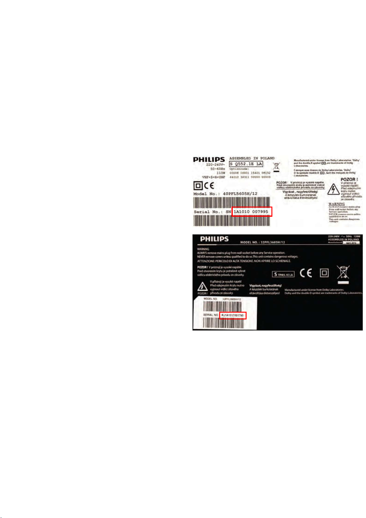
For the third digit, the numbers 1...9 and the characters
A...Z can be used, so in total: 9 plus 26= 35 different
B.O.M.s can be indicated by the third digit of the serial
number.
Identification: The bottom line of a type plate gives a
14-digit serial number. Digits 1 and 2 refer to the production
centre (e.g. SN is Lysomice, RJ is Kobierzyce), digit 3
refers to the B.O.M. code, digit 4 refers to the Service
version change code, digits 5 and 6 refer to the production
year, and digits 7 and 8 refer to production week (in
example below it is 2010 week 10 / 2010 week 17). The 6
last digits contain the serial number.
2.3.6 Alternative BOM identification
It should be noted that on the European Service website,
“Alternative BOM” is referred to as “Design variant”.
The third digit in the serial number (example:
AG2B0335000001) indicates the number of the alternative
B.O.M. (Bill Of Materials) that has been used for producing
the specific TV set. In general, it is possible that the same
TV model on the market is produced with e.g. two different
types of displays, coming from two different suppliers. This
will then result in sets which have the same CTN
(Commercial Type Number; e.g. 28PW9515/12) but which
have a different B.O.M. number.
By looking at the third digit of the serial number, one can
identify which B.O.M. is used for the TV set he is working
with. If the third digit of the serial number contains the
number “1” (example: AG1B033500001), then the TV set
has been manufactured according to B.O.M. number 1. If
the third digit is a “2” (example: AG2B0335000001), then
the set has been produced according to B.O.M. no. 2. This
is important for ordering the correct spare parts!
Figure 3-1 Serial number (example)
2.3.7 Board Level Repair (BLR) or Component Level
Repair (CLR)
If a board is defective, consult your repair procedure to
decide if the board has to be exchanged or if it should be
repaired on component level.
If your repair procedure says the board should be
exchanged completely, do not solder on the defective board.
Otherwise, it cannot be returned to the O.E.M. supplier for
back charging!
2.3.8 Practical Service Precautions
• It makes sense to avoid exposure to electrical shock.
While some sources are expected to have a possible
dangerous impact, others of quite high potential are of
limited current and are sometimes held in less regard.
Page 7

• Always respect voltages. While some may not be
dangerous in themselves, they can cause unexpected
reactions that are best avoided. Before reaching into a
powered TV set, it is best to test the high voltage
insulation. It is easy to do, and is a good service
precaution.
2.4 Abbreviation List
0/6/12 SCART switch control signal on A/V board.
0 = loop through (AUX to TV),6 = play 16 :
9 format, 12 = play 4 : 3 format
DNR Digital Noise Reduction: noise reduction
feature of the set
AARA Automatic Aspect Ratio Adaptation:
algorithm that adapts aspect ratio to
remove horizontal black bars; keeps the
original aspect ratio
ACI Automatic Channel Installation: algorithm
that installs TV channels directly from a
cable network by means of a predefined
TXT page
ADC Analogue to Digital Converter
AFC Automatic Frequency Control: control
signal used to tune to the correct
frequency
AGC Automatic Gain Control: algorithm that
ontrols the video input of the feature box
AM Amplitude Modulation
AP Asia Pacific
AR Aspect Ratio: 4 by 3 or 16 by 9
ASF Auto Screen Fit: algorithm that adapts
aspect ratio to remove horizontal black
bars without discarding video information
ATSC Advanced Television Systems Committee,
the digital TV standard in the USA
ATV See Auto TV
Auto TV A hardware and software control system
that measures picture content, and adapts
image parameters in a dynamic way
AV External Audio Video
AVC Audio Video Controller
AVIP Audio Video Input Processor
B/G Monochrome TV system. Sound carrier
distance is 5.5 MHz
BDS Business Display Solutions (iTV)
BLR Board-Level Repair
BTSC Broadcast Television Standard Committee.
Multiplex FM stereo sound system,
originating from the USA and used e.g. in
LATAM and AP-NTSC countries
B-TXT Blue TeleteXT
C Centre channel (audio)
CEC Consumer Electronics Control bus: remote
control bus on HDMI connections
CL Constant Level: audio output to connect
with an external amplifier
CLR Component Level Repair
ComPair Computer aided rePair
CP Connected Planet / Copy Protection
CSM Customer Service Mode
CTI Color Transient Improvement: manipulates
steepness of chroma transients
CVBS Composite Video Blanking and
Synchronization
DAC Digital to Analogue Converter
DBE Dynamic Bass Enhancement: extra low
frequency amplification
DCM Data Communication Module. Also
referred to as System Card or Smartcard
(for iTV).
DDC See “E-DDC”
D/K Monochrome TV system. Sound carrier
distance is 6.5 MHz
DFI Dynamic Frame Insertion
DFU Directions For Use: owner's manual
DMR Digital Media Reader: card reader
DMSD Digital Multi Standard Decoding
DNM Digital Natural Motion
DRAM Dynamic RAM
DRM Digital Rights Management
DSP Digital Signal Processing
DST Dealer Service Tool: special remote control
designed for service technicians
DTCP Digital Transmission Content Protection; A
protocol for protecting digital audio/video
content that is traversing a high speed
serial bus, such as IEEE-1394
DVB-C Digital Video Broadcast - Cable
DVB-T Digital Video Broadcast - Terrestrial
DVD Digital Versatile Disc
DVI(-d) Digital Visual Interface (d= digital only)
E-DDC Enhanced Display Data Channel (VESA
standard for communication channel and
display). Using E-DDC, the video source
can read the EDID information form the
display.
Page 8

EDID Extended Display Identification Data
(VESA standard)
EEPROM Electrically Erasable and Programmable
Read Only Memory
EMI Electro Magnetic Interference
EPG Electronic Program Guide
EPLD Erasable Programmable Logic Device
EU Europe
EXT EXTernal (source), entering the set by
SCART or by cinches (jacks)
FDS Full Dual Screen (same as FDW)
FDW Full Dual Window (same as FDS)
FLASH FLASH memory
FM Field Memory or Frequency Modulation
FPGA Field-Programmable Gate Array
FTV Flat TeleVision
Gb/s Giga bits per second
G-TXT Green TeleteXT
H H_sync to the module
HD High Definition
HDD Hard Disk Drive
HDCP High-bandwidth Digital Content Protection:
A “key” encoded into the HDMI/DVI signal
that prevents video data piracy. If a source
is HDCP coded and connected via
HDMI/DVI without the proper HDCP
decoding, the picture is put into a “snow
vision” mode or changed to a low
resolution. For normal content distribution
the source and the display device must be
enabled for HDCP “software key”
decoding.
HDMI High Definition Multimedia Interface
HP HeadPhone
I Monochrome TV system. Sound carrier
distance is 6.0 MHz
I2C Inter IC bus
I2D Inter IC Data bus
I2S Inter IC Sound bus
IF Intermediate Frequency
IR Infra Red
IRQ Interrupt Request
ITU-656 The ITU Radio communication Sector
(ITU-R) is a standards body subcommittee
of the International Telecommunication
Union relating to radio communication.
ITU-656 (a.k.a. SDI), is a digitized video
format used for broadcast grade video.
Uncompressed digital component or digital
composite signals can be used. The SDI
signal is self-synchronizing, uses 8 bit or
10 bit data words, and has a maximum
data rate of 270 Mbit/s, with a minimum
bandwidth of 135 MHz.
iTV Institutional TeleVision; TV sets for hotels,
hospitals etc.
LS Last Status; The settings last chosen by
the customer and read and stored in RAM
or in the NVM. They are called at start-up
of the set to configure it according to the
customer's preferences
LATAM Latin America
LCD Liquid Crystal Display
LED Light Emitting Diode
L/L' Monochrome TV system. Sound carrier
distance is 6.5 MHz. L' is Band I, L is all
bands except for Band I
LPL LG.Philips LCD (supplier)
LS Loudspeaker
LVDS Low Voltage Differential Signalling
Mbps Mega bits per second
M/N Monochrome TV system. Sound carrier
distance is 4.5 MHz
MHEG Part of a set of international standards
related to the presentation of multimedia
information, standardised by the
Multimedia and Hypermedia Experts
Group. It is commonly used as a language
to describe interactive television services
MIPS Microprocessor without Interlocked
Pipeline-Stages; A RISC-based
microprocessor
MOP Matrix Output Processor
MOSFET Metal Oxide Silicon Field Effect Transistor,
switching device
MPEG Motion Pictures Experts Group
MPIF Multi Platform InterFace
MUTE MUTE Line
MTV Mainstream TV: TV-mode with Consumer
TV features enabled (iTV)
NC Not Connected
NICAM Near Instantaneous Compounded Audio
Multiplexing. This is a digital sound system,
mainly used in Europe.
NTC Negative Temperature Coefficient,
non-linear resistor
Page 9

NTSC National Television Standard Committee.
Color system mainly used in North
America and Japan. Color carrier NTSC
M/N= 3.579545 MHz, NTSC 4.43=
4.433619 MHz (this is a VCR norm, it is
not transmitted off-air)
NVM Non-Volatile Memory: IC containing TV
related data such as alignments
O/C Open Circuit
OSD On Screen Display
OAD Over the Air Download. Method of
software upgrade via RF transmission.
Upgrade software is broadcasted in TS
with TV channels.
OTC On screen display Teletext and Control;
also called Artistic (SAA5800)
P50 Project 50: communication protocol
between TV and peripherals
PAL Phase Alternating Line. Color system
mainly used in West Europe (colour carrier
= 4.433619 MHz) and South America
(colour carrier PAL M = 3.575612 MHz and
PAL N = 3.582056 MHz)
PCB Printed Circuit Board (same as “PWB”)
PCM Pulse Code Modulation
PDP Plasma Display Panel
PFC Power Factor Corrector (or
Pre-conditioner)
PIP Picture In Picture
PLL Phase Locked Loop. Used for e.g. FST
tuning systems. The customer can give
directly the desired frequency
POD Point Of Deployment: a removable CAM
module, implementing the CA system for a
host (e.g. a TV-set)
POR Power On Reset, signal to reset the uP
PSDL Power Supply for Direct view LED
backlight with 2D-dimming
PSL Power Supply with integrated LED drivers
PSLS Power Supply with integrated LED drivers
with added Scanning functionality
PTC Positive Temperature Coefficient,
non-linear resistor
PWB Printed Wiring Board (same as “PCB”)
PWM Pulse Width Modulation
QRC Quasi Resonant Converter
QTNR Quality Temporal Noise Reduction
QVCP Quality Video Composition Processor
RAM Random Access Memory
RGB Red, Green, and Blue. The primary color
signals for TV. By mixing levels of R, G,
and B, all colors (Y/C) are reproduced.
RC Remote Control
RC5 / RC6 Signal protocol from the remote control
receiver
RESET RESET signal
ROM Read Only Memory
RSDS Reduced Swing Differential Signalling data
interface
R-TXT Red TeleteXT
SAM Service Alignment Mode
S/C Short Circuit
SCART Syndicat des Constructeurs d'Appareils
Radiorécepteurs et Téléviseurs
SCL Serial Clock I2C
SCL-F CLock Signal on Fast I2C bus
SD Standard Definition
SDA Serial Data I2C
SDA-F DAta Signal on Fast I2C bus
SDI Serial Digital Interface, see “ITU-656”
SDRAM Synchronous DRAM
SECAM SEequence Couleur Avec Mémoire.
Colour system mainly used in France and
East Europe. Colour carriers = 4.406250
MHz and 4.250000 MHz
SIF Sound Intermediate Frequency
SMPS Switched Mode Power Supply
SoC System on Chip
SOG Sync On Green
SOPS Self Oscillating Power Supply
SPI Serial Peripheral Interface bus; a 4-wire
synchronous serial data link standard
S/PDIF Sony Philips Digital InterFace
SRAM Static RAM
SRP Service Reference Protocol
SSB Small Signal Board
SSC Spread Spectrum Clocking, used to
reduce the effects of EMI
STB Set Top Box
STBY STand-BY
SVGA 800 × 600 (4:3)
SVHS Super Video Home System
SW Software
SWAN Spatial temporal Weighted Averaging
Noise reduction
SXGA 1280 × 1024
Page 10

TFT Thin Film Transistor
THD Total Harmonic Distortion
TMDS Transmission Minimized Differential
Signalling
TS Transport Stream
TXT TeleteXT
TXT-DW Dual Window with TeleteXT
UI User Interface
uP Microprocessor
UXGA 1600 × 1200 (4:3)
V V-sync to the module
VESA Video Electronics Standards Association
VGA 640 × 480 (4:3)
VL Variable Level out: processed audio output
toward external amplifier
VSB Vestigial Side Band; modulation method
WYSIWYR What You See Is What You Record: record
selection that follows main picture and
sound
WXGA 1280 × 768 (15:9)
XTAL Quartz crystal
XGA 1024 × 768 (4:3)
Y Luminance signal
Y/C Luminance (Y) and Chrominance (C)
signal
YPbPr Component video. Luminance and scaled
color difference signals (B-Y and R-Y)
YUV Component video
Page 11
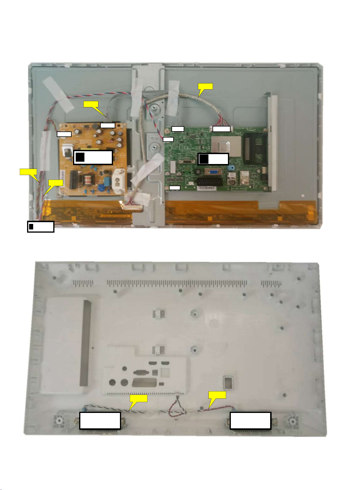
3. Mechanical Instructions
(1054)
401
CN
8605
9101
J
ECN
701 ECN
401 ECN
408
1
701
ECN
8605
LOUDSPEAKER
LOUDSPEAKER
3.1 Cable Dressing
IR/LED BOARD
(1056)
MAIN POWER SUPPLY
A
CN
CN
CN
B
CN60
Cable dressing (24" 5603 series)
CN408
SSB (1053)
(1184)
ECN601
Back cover overview (24" 5603 series)
ECN601
(1184)
Page 12
KEY BOARD
E
(1054)
9101
ECN
701
ECN
401 to Key&IR
ECN
408
701
IR
/LED
J
ECN
601
LOUDSPEAKER
LOUDSPEAKER
(1184)
ECN
601
BOARD
(1056)
MAIN POWER SUPPLY
A
(1184)
CN8601
CN
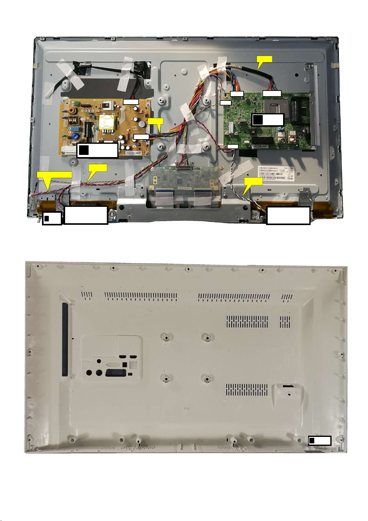
Cable dressing (32" 5603 series)
CN401
CN
CN601
B
CN408
SSB (1053)
(1057)
Back cover overview (32" 5603 series)
Page 13

3.2 Assembly/Panel Removal
1
3.2.1 Stand removal
1. Remove the fixation screws [1] that secure the stand.
2. Take the stand bracket out from the set.
1
(24” 5603 Series)
1
1
(32” 5603 Series)
Page 14
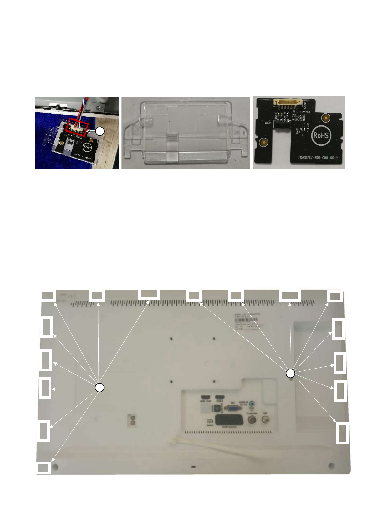
3.2.2 IR board Control Unit
1. Unplug connector [2] from the IR board control unit.
2. Remove the IR lens, IR board from the DECO_REAR_COVER.
When defective, replace the whole unit.
2
3.2.3 Rear Cover
Warning: Disconnect the mains power cord before removing the rear cover.
24” 5603 Series:
1. Releasing the clips carefully at the indicated areas [2] that secure the back cover.
2. Unplug connector [3] carefully, as the speaker is catch on back cover.
3. Gently lift the rear cover from the TV. Make sure that wires and cables are not damaged while lifting the rear cover from the set.
2
2
Page 15
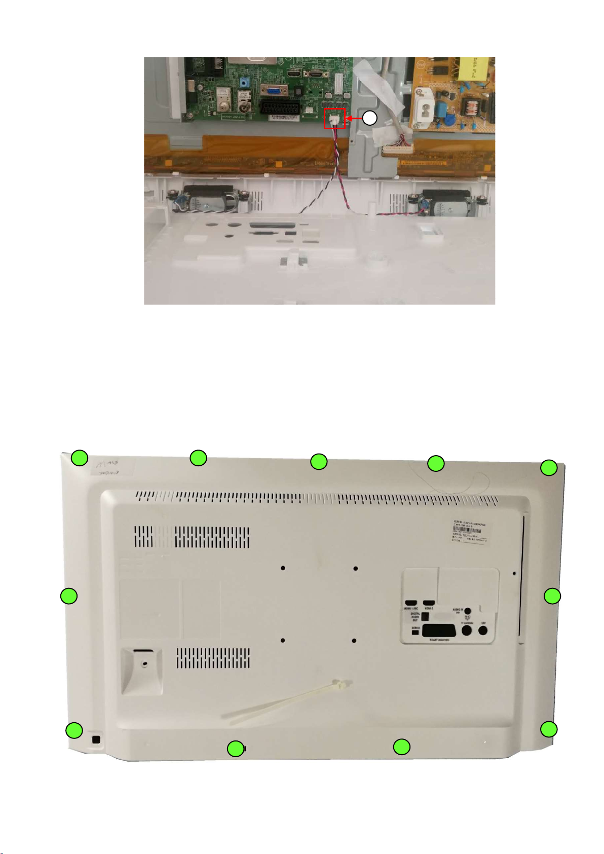
3
32” 5603 Series:
1. Remove all the fixation screws [2] that secure the back cover.
2. Unplug the connector which from SSB to Key board carefully.
3. Gently lift the rear cover from the TV. Make sure that wires and cables are not damaged while lifting the rear cover from the set.
2
2
2
2
2
2
2
2
2
2
2
Page 16
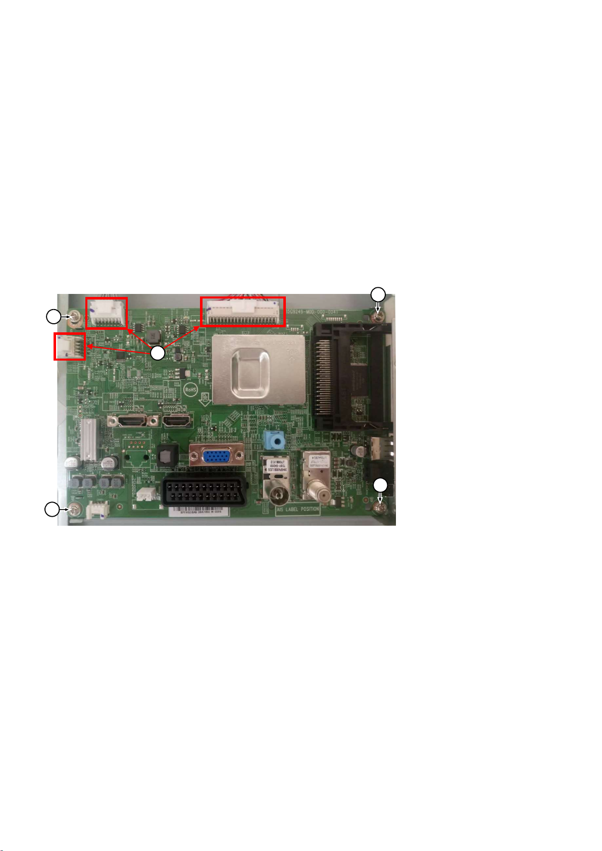
3
3.2.4 Keyboard Control Unit
1. Release the connector from the SSB Board.
Caution: be careful, the Keyboard is catch on the Back cover, please be careful to avoid damage the fragile connectors!
2. Remove all the fixation screws and connector from the keyboard control panel then take it out from the Back cover.
When defective, replace the whole unit.
3.2.5 Small Signal Board (SSB)
Caution: it is mandatory to remount all different screws at their original position during re-assembly. Failure to do so may result in damaging the
SSB.
1. Unplug all connectors [2] .
2. Remove all the fixation screws [3] from the SSB.
3. The SSB can now be shifted from side connector cover, then lifted and taken out of the I/O bracket.
3
2
3
3
3.2.6 Power Supply Unit (PSU)
Caution: it is mandatory to remount all different screws at their original position during re-assembly. Failure to do so may result in damaging the
PSU.
1. Gently unplug all connectors from the PSU.
2. Remove all fixation screws from the PSU.
3. The PSU can be taken out of the set now.
3.2.7 Speakers
1. Gently release the tapes that secure the speaker cables.
2. Unplug the speaker connector from the SSB.
3. Take the speakers out.
When defective, replace the both units.
Page 17

3.2.8 LCD Panel
1. Remove the SSB as described earlier.
2. Remove the PSU as described earlier.
3. Remove the keyboard control panel as described earlier.
4. Remove the stand bracket as described earlier.
5. Remove the IR/LED as described earlier.
6. Remove the fixations screws that fix the metal clamps to the front bezel. Take out those clamps.
7. Remove all other metal parts not belonging to the panel.
8. Lift the LCD Panel from the bezel.
When defective, replace the whole unit.
Page 18

4. Service Modes
4.1 Service Modes
The Service Mode feature is split into following parts:
Service Alignment Mode (SAM).
Factory Mode.
Customer Service Mode (CSM).SAM and the Factory mode offer features, which can be used by the Service engineer to repair/align a TV set.
SAM and the Factory mode offer features, which can be used by the Service engineer to repair/align a TV set. Some features are:
Make alignments (e.g. White Tone), reset the error buffer(SAM and Factory Mode).
Display information (“SAM” indication in upper right corner of screen, error buffer, software version, operating hours,options and option codes,
sub menus).
The CSM is a Service Mode that can be enabled by the consumer. The CSM displays diagnosis information, which the customer can forward to the
dealer or call centre. In CSM mode, “CSM”, is displayed in the top right corner of the screen. The information provided in CSM and the purpose of
CSM is to:
Increase the home repair hit rate.
Decrease the number of nuisance calls.
Solved customers’ problem without home visit.
Note: For the new model range, a new remote control (RC) is used with some renamed buttons. This has an impact on the activation of the Service
modes. For instance the old “MENU” button is now called “HOME” (or is indicated by a “house” icon).
4.2 Service Alignment Mode (SAM)
Purpose
To modify the NVM.
To display/clear the error code buffer.
To perform alignments.
Specifications
Operation hours counter (maximum five digits displayed).
Software version, error codes, and option settings display.
Error buffer clearing.
Option settings.
Software alignments (White Tone).
NVM Editor.
Set screen mode to full screen (all content is visible).
How to Activate SAM
To activate SAM, use one of the following methods:
Press the following key sequence on the remote control transmitter: “062596”, directly followed by the “INFO/OK” button. Do not allow the
display to time out between entries while keying the sequence.
Or via ComPair.
After entering SAM, the following items are displayed,
with “SAM” in the upper right corner of the screen to indicate that the television is in Service Alignment Mode.
How to Navigate
In the SAM menu, select menu items with the UP/DOWN keys on the remote control transmitter. The selected item will be indicated. When not
all menu items fit on the screen, use the UP/DOWN keys to display the next/previous menu items.
Page 19
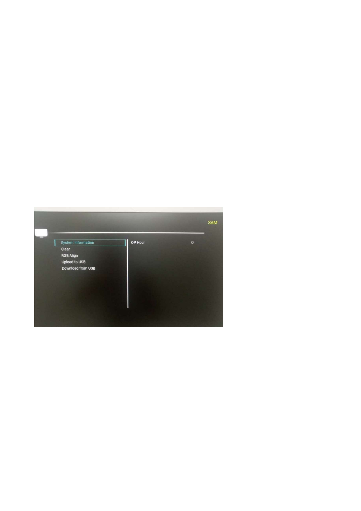
With the “LEFT/RIGHT” keys, it is possible to:
– (De) activate the selected menu item.
– (De) activate the selected sub menu.
– Change the value of the selected menu item.
When you press the MENU button once while in top level SAM, the set will switch to the normal user menu (with the SAM mode still active in the
background).
How to Store SAM Settings
To store the settings changed in SAM mode (except the RGB Align settings), leave the top level SAM menu by using the POWER button on the
remote control transmitter or the television set. The mentioned exceptions must be stored separately via the STORE button.
How to Exit SAM
Use one of the following methods:
Switch the set to STANDBY by pressing the mains button on the remote control transmitter or the television set.
Via a standard RC-transmitter, key in “00” sequence.
Note: When the TV is switched “off” by a power interrupt while in SAM, the TV will show up in “normal operation mode” as soon as the power is
supplied again. The error buffer will not be cleared.
SAM mode overview
4.3 Factory mode:
Purpose
To perform extended alignments.
Specifications
Displaying and or changing Panel ID information.
Displaying and or changing Tuner ID information.
Error buffer clearing.
Various software alignment settings.
Testpattern displaying.
Public Broadcasting Service password Reset.
etc.
How to Activate the Factory mode
To activate the Factory mode, use the following method:
Page 20
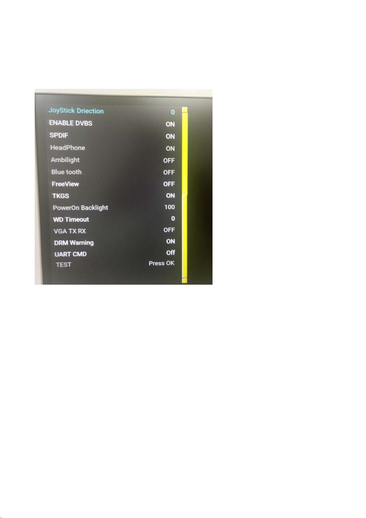
Press the following key sequence on the remote control transmitter: from the “menu/home” press “1999”, directly followed by the
“Back/Return” button. Do not allow the display to time out between entries while keying the sequence.
After entering the Factory mode, we can see many items displayed, use the UP/DOWN keys to display the next/previous menu items
Factory mode overview
How to Exit the Factory mode
Use one of the following methods:
Select EXIT_FACTORY from the menu and press the “OK” button.
Note: When the TV is switched “off” by a power interrupt, or normal switch to “stand-by” while in the factory mode, the TV will show up in “normal
operation mode” as soon as the power is supplied again. The error buffer will not be cleared.
4.4 Customer Service Mode (CSM)
Purpose
The Customer Service Mode shows error codes and information on the TVs operation settings. The call centre can instruct the customer (by
telephone) to enter CSM in order to identify the status of the set. This helps the call centre to diagnose problems and failures in the TV set before
making a service call.
The CSM is a read-only mode; therefore, modifications are not possible in this mode.
Specifications
Ignore “Service unfriendly modes”.
Line number for every
line (to make CSM language independent).
Set the screen mode to full
screen (all contents on screen is visible).
After leaving the Customer Service Mode, the original settings are restored.
Possibility to use “CH+” or “CH-” for channel surfing, or enter the specific channel number on the RC.
Page 21
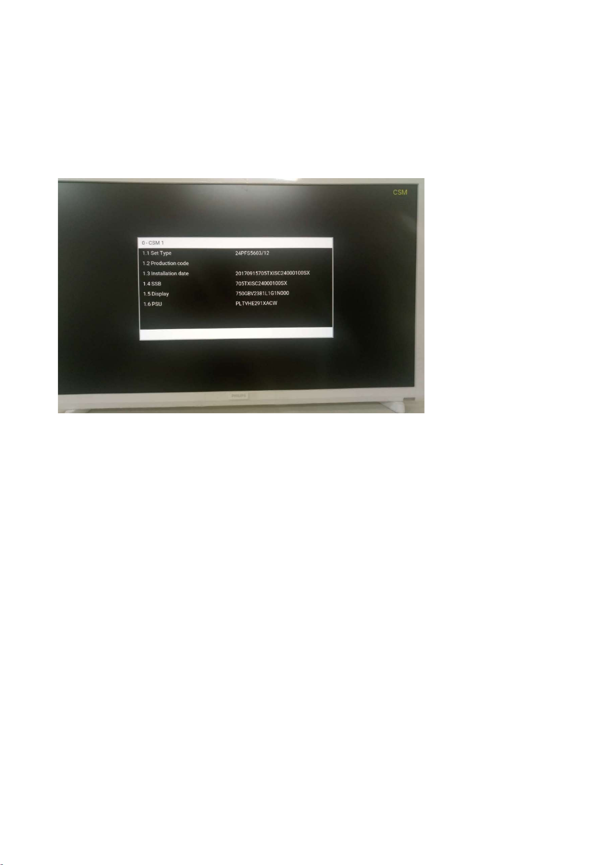
How to Activate CSM
To activate CSM, press the following key sequence on a standard remote control transmitter: “123654” (do not allow the display to time out
between entries while keying the sequence). After entering the Customer Service Mode, the following items are displayed. use the Right/Left keys
to display the next/previous menu items
Note: Activation of the CSM is only possible if there is no (user) menu on the screen!
CSM Overview
How to Navigate
By means of the “CURSOR-DOWN/UP” knob (or the scroll wheel) on the RC-transmitter, can be navigated through the menus.
How to Exit CSM
To exit CSM, use one of the following methods.
Press the MENU/HOME button on the remote control transmitter.
Press the POWER button on the remote control transmitter.
Press the POWER button on the television set.
Page 22
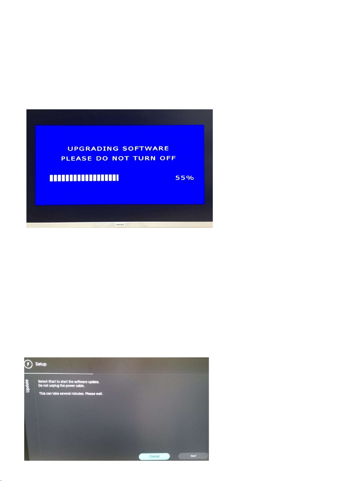
5. Software Upgrading, Error code and Panel Code
5.1.1. The following update is for .pkg file.
1. Rename the file to “upgrade_loader.pkg”.
2. Prepare a USB memory (File format: FLAT, Size: 1G~8G).
3. Copy the software to USB flash disk (root directory).
4. Switch off the TV and Insert the USB memory stick that contains the software update files in one of the TV’s USB 2.0 port.
5. Switch on the TV. The TV will detect the USB memory stick automatically. Then a window jumps out as below:
6. When the TV software is updated, the TV will turn on again automatically. Remove your USB flash drive.
7. We can enter in CSM to check the current software version.
5.1.2. The following update is for .upg file.
Step 1: Ready for F/W Upgrade
1. Rename the file to “Autorun.upg”.
2. Prepare a USB memory (File format: FLAT, Size: 1G~8G).
3. Copy the software to USB flash disk (root directory).
Note the version of this F/W before you change the software file name.
Step 2: F/W Upgrade
1. Plug the USB memory on the TV’s USB 2.0 port.
2. AC on (Power plug).
3. Press [Start] to start software upgrade
Page 23
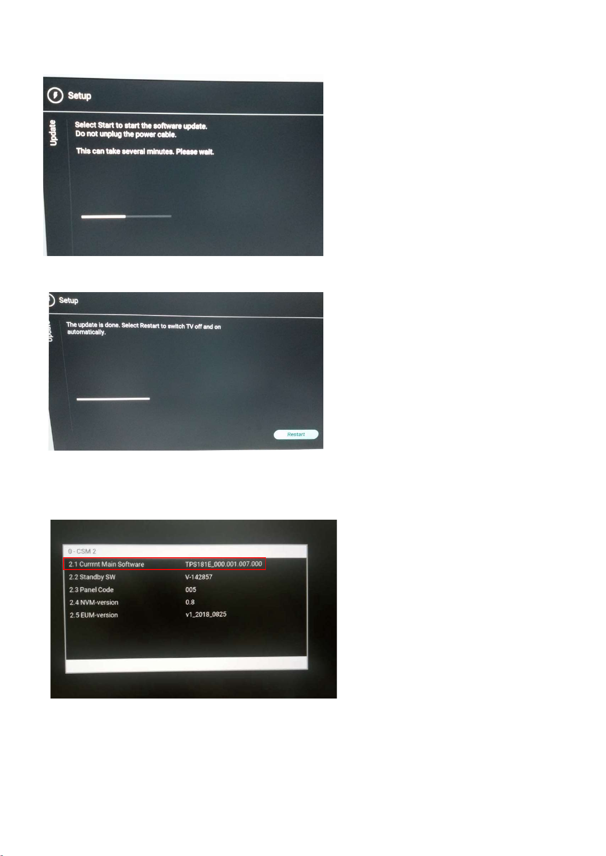
4. Upgrade in progress.
5. After software upgrade complete, select [Restart] to reboot TV.
Step 3: Check the SW version
1. After burning software, TV will restart.
2. Press “123654”, enter Customer Service Mode to check if the software version is correct.
Caution: Please make sure that software upgrade is finished before unplug the USB and AC power!
Page 24

5.1 Error Code
5.2.1 Introduction
Error codes are required to indicate failures in the TV set. In principle a unique error code is available for every:
• Activated (SW) protection.
• Failing I2C device.
• General I2C error.
The last five errors, stored in the NVM, are shown in the Service menu’s. This is called the error buffer.
The error code buffer contains all errors detected since the last time the buffer was erased. The buffer is written from left to right. When an error occurs that
is not yet in the error code buffer, it is displayed at the left side and all other errors shift one position to the right.
An error will be added to the buffer if this error differs from any error in the buffer. The last found error is displayed on the left.
An error with a designated error code never leads to a deadlock situation. It must always be diagnosable (e.g. error buffer via OSD or blinking LED).
In case a failure identified by an error code automatically results in other error codes (cause and effect), only the error code of the MAIN failure is displayed.
5.2.2 How to Read the Error Buffer
You can read the error buffer in three ways:
• On screen via the SAM/CSM (if you have a picture).
Example:
– ERROR: 000 000 000 000 000: No errors detected
– ERROR: 013 000 000 000 000: Error code 13 is the last and only detected error
– ERROR: 034 013 000 000 000: Error code 13 was detected first and error code 34 is the last detected (newest) error
• Via the blinking LED procedure (when you have no picture).
5.2.3 Error codes overview
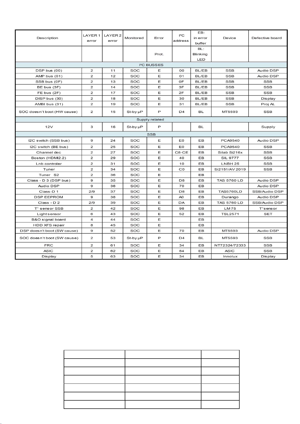
In this chassis only “layer 2” error codes are available and point to problems on the SSB. They are triggered by LED blinking
when CSM is activated. Only the following layer 2 errors are defined:
Page 25
5.2.4 How to Clear the Error Buffer
The error code buffer is cleared in the following cases:
• By using the CLEAR command in the SAM menu
• By using the CLEAR command in the Factory mode:
• By using the following key sequence on the remote control transmitter: “062599” directly followed by the OK button.
• If the contents of the error buffer have not changed for 50 hours, the error buffer resets automatically.
Note: If you exit SAM by disconnecting the mains from the television set, the error buffer is not reset.
5.2 Panel Code
Press the following key sequence on a standard RC transmitter: “062598” directly followed by MENU and “xxx”, where “xxx” is a 3 digit decimal value
of the panel type: see column “Display Code” in below tab. After resetting the Display Code, restart the set immediately.
CTN_ALT BOM# Panel Type Display Code
24PFS5603/12 TPM238WF1-LF1L0.Q S1G 5
24PFT5603/05 TPM238WF1-LF1L0.Q S1G 5
24PFT5603/12 TPM238WF1-LF1L0.Q S1G 5
32PFS5603/12 TPT315B5-FHBN0.K S49P0L 6
32PFT5603/05 TPT315B5-FHBN0.K S49P0L 6
32PFT5603/12 TPT315B5-FHBN0.K S49P0L 6
Page 26
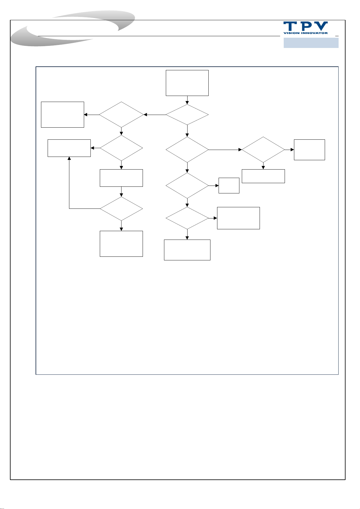
Trouble shooting
Picture-related
2016年12月10日
2016/4/8
Ask Photo
SW
issue
N
Intermittent
problem ?
Y
Y
SW latest ?
N
Update SW
N
Problem
solved ?
Y
Finish
Y
Picture ?
N
Backlight?
N
LED working ?
Y
Sound ?
SW+SSB
Y
N
PSU/SSB
Y
PSU+ Panel
Menu Smarkt
function?
N
SSB+LVDS+Panel
RAM
Y
Signal
issue
Page 27
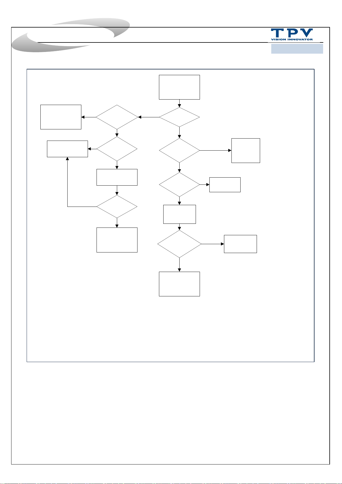
Trouble shooting
Audio/Sound-
related
2016年12月10日
2016/4/8
HW
issue
SW
N
Intermittent
problem ?
Y
Y
SW latest ?
N
Update SW
N
Problem
solved ?
Y
Finish
Y
Sound ?
N
Mute ?
N
Extra device
connect?
N
Factory
setting
Sound back ? Setting issue
N
Y
Y
Check extra
Y
device
Setting
issue
SSB+SPK
Page 28
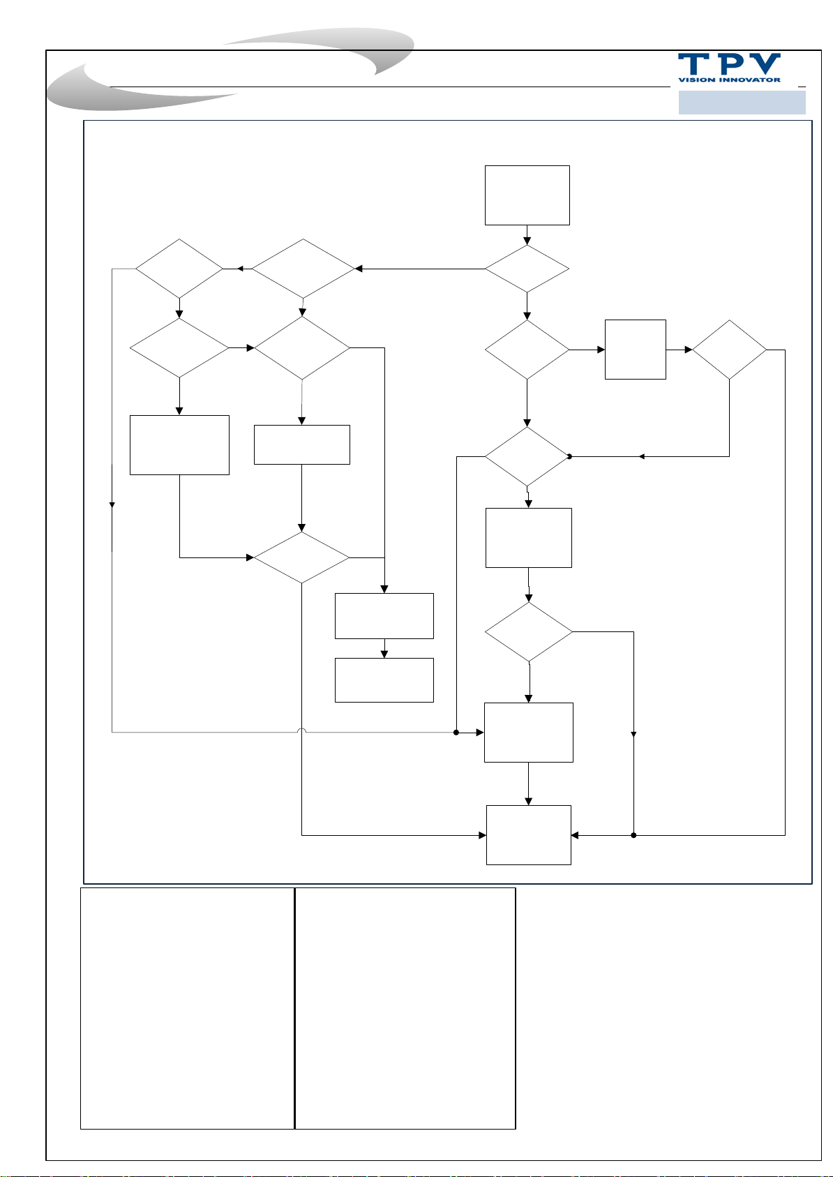
Trouble shooting system
N
Smart
function
issue ?
N
Intermittent
problem ?
Remark2:
Y
Y
2016年4月11日
2016/12/11
System related
Remark1:
Y
TV start
up ?
N
Network
connect ?
N
Connect network
Y
SW latest ?
N
Update SW
Problem
solved ?
Y
Y
N
SW issue
Commerce way
SCC
available ?
Y
Execute
SCC
Problem
solved ?
Y
N
N
SW update
available ?
Y
SW update
N
Problem
Y
solved ?
N
HW repair
Remark1 : What is System related issue ?
1.Permanent reboots
2.Intermittent reboots
3.No function, no standby LED (set dead)
4.No function, blinking LED
5.Set freezes, intermittently
6.Slow response to user interaction
7.Switches ON by itself
8.Switches Off by itself
9.Stuck in standby mode / unable to start up
10.Stuck on PHILIPS / ANDROID logo
11.CAM not recognized by TV
12.CAM authentication issue
13.Misc CAM issue
14.IP-EPG issues
15.BC-EPG issues
16.PVR issues w/ BC-EPG
17.PVR issues w/ IP-EPG
18.PVR issues / generic
19.EDFU-related issue
20.Features not available in UI / cannot be activated
Remark2 : How to judge intermittent issue ?
1.When the problem happened can be solved by:
1)AC off AC on
2)DC off DC on
3)RC switch different source
2.The problem intermittent happened
Finish
Page 29
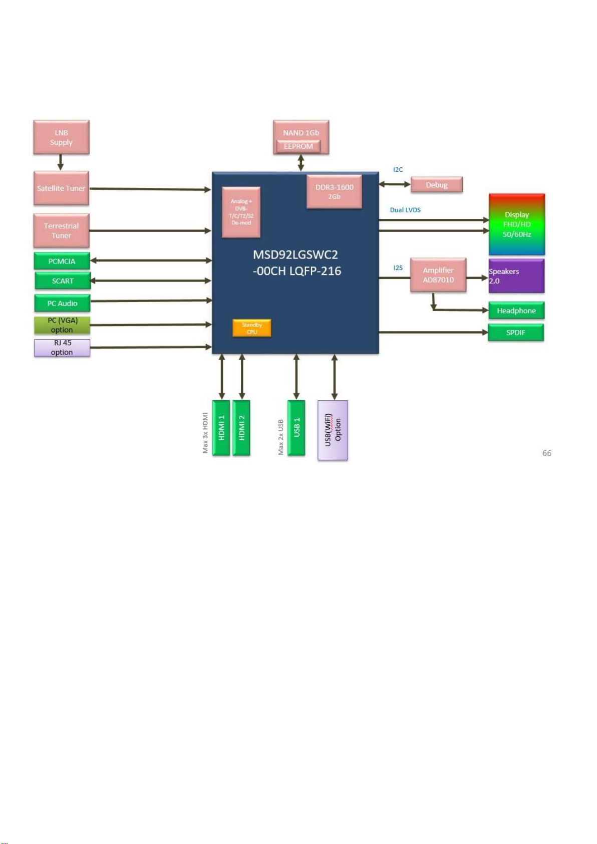
7. Electrical Diagram
7.1 Block diagram
Page 30
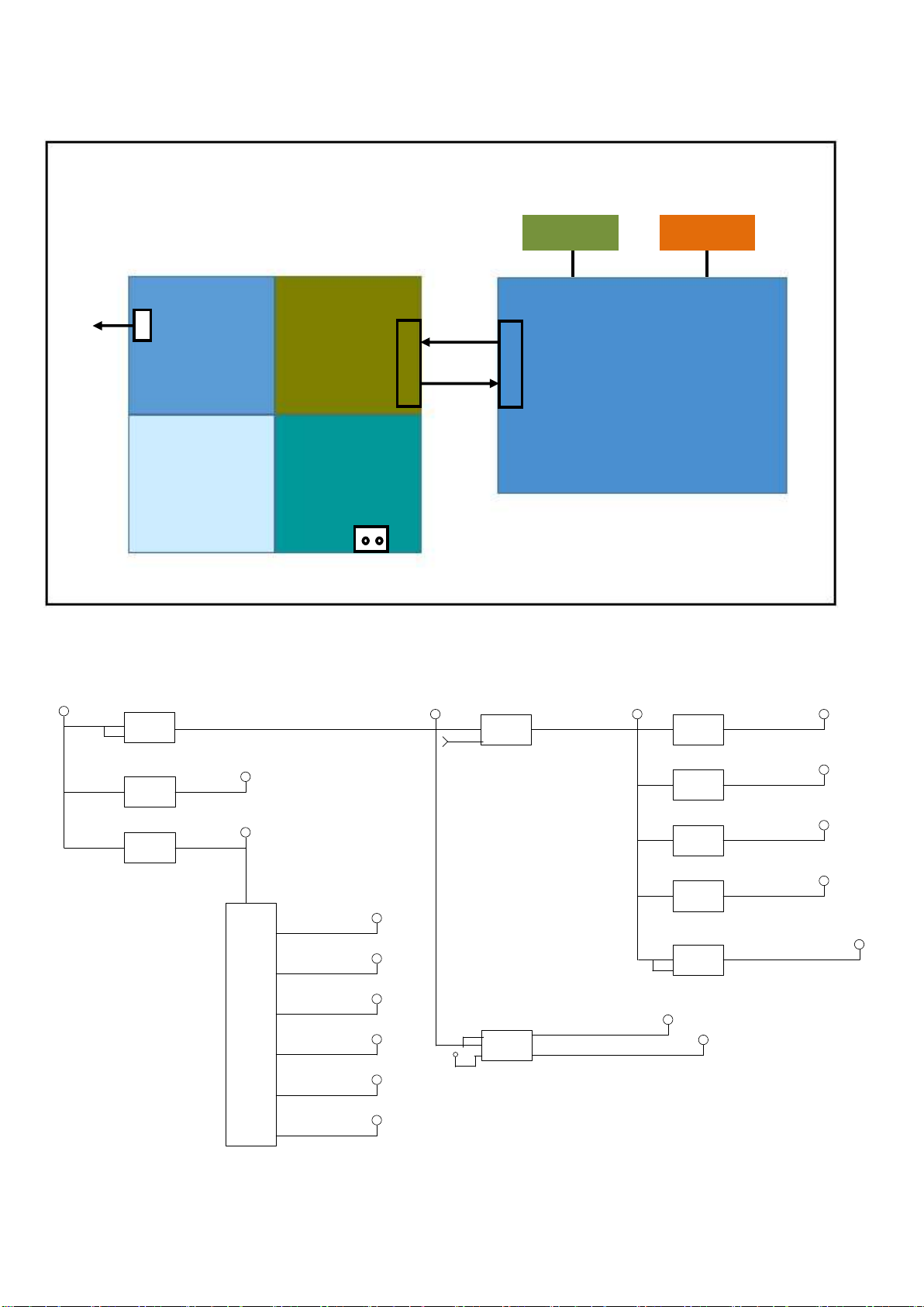
7.2 Power Supply
CN
701
12V
AUDIO
AMP
Main filter
Power architecture of this platform:
Display power
LVDS
12V
Platform power
CN8605 for 715G7735P
CN8601 for 715G7734P
PFC
For 32”
7.3 Power tree
Power Board System Supply +12V_N ormal/ 20.6W/ 1722mA
Power Board Audio Supply +12V_Au dio/ 10W/ 925mA
+12V_Normal U701
12V/11.6W/972 mA
12V/3W/250mA
DC/DC RT620 6BHGSP 5.5A 18V SOP-8
EN
U202
DC/DC MP812 4GD Z 500mA 14V
QFN-1
VCC_LNBA
DIM
ON/OFF
PS_ON
12V
12V_A
5V_STB
AC-input +
AC IN
Platform
MSD92L
Q701
+5V_Standby +1.5V_DDR
2100mA
MOSFET MTP2 317N3 -5.8A -20V
5.8A
EN
PWR_ON/OFF
1575mA
+5V_Normal
200mA
375mA
U703
LDO AZ1117 CD-ADJTRG1 1A adj TO-2 52
LDO AZ1117C H- 3.3TRG1/3.3V 1.35A
+3.3V_TUU101
12V/6W/500mA
Q404
FET AO4449 -7A/-30V
PANEL_POWER
12V/6W/500m A
U456
DC/DC G5567SQ G1U 8V to 14V 4.25A
VHAVDD_8.8V _50mA
AVDD_17.6V_ 800mA
VGL_-7.9V
VGH_30V_100 mA
VCOM_8.25V_ 80mA
DVDD_3.3V_3 50mA
U702
DC/DC M5723 B-33F61U 2A 6V MSOP-1 0(FD)
Buck IC 2A for 1.15V_Enable by E N1
LDO IC 400m A for +3.3V_standby_E nable by EN2
EN2
300mA
+3.3V_ Standby
LDO
EN1
Buck
U104
Power Switc h APL3511CBI-TRG
500mA
Power Switc h APL3511CBI-TRG
500mA
LDO IC G91 41T11U SOT23-5 (600mA)
220mA
EN
+3.3V_Standby
NT72334
+1.15V_VDD C
+5V_PCMCIA
+5V_USBU901
+3.3V_Norma lU602
Page 31
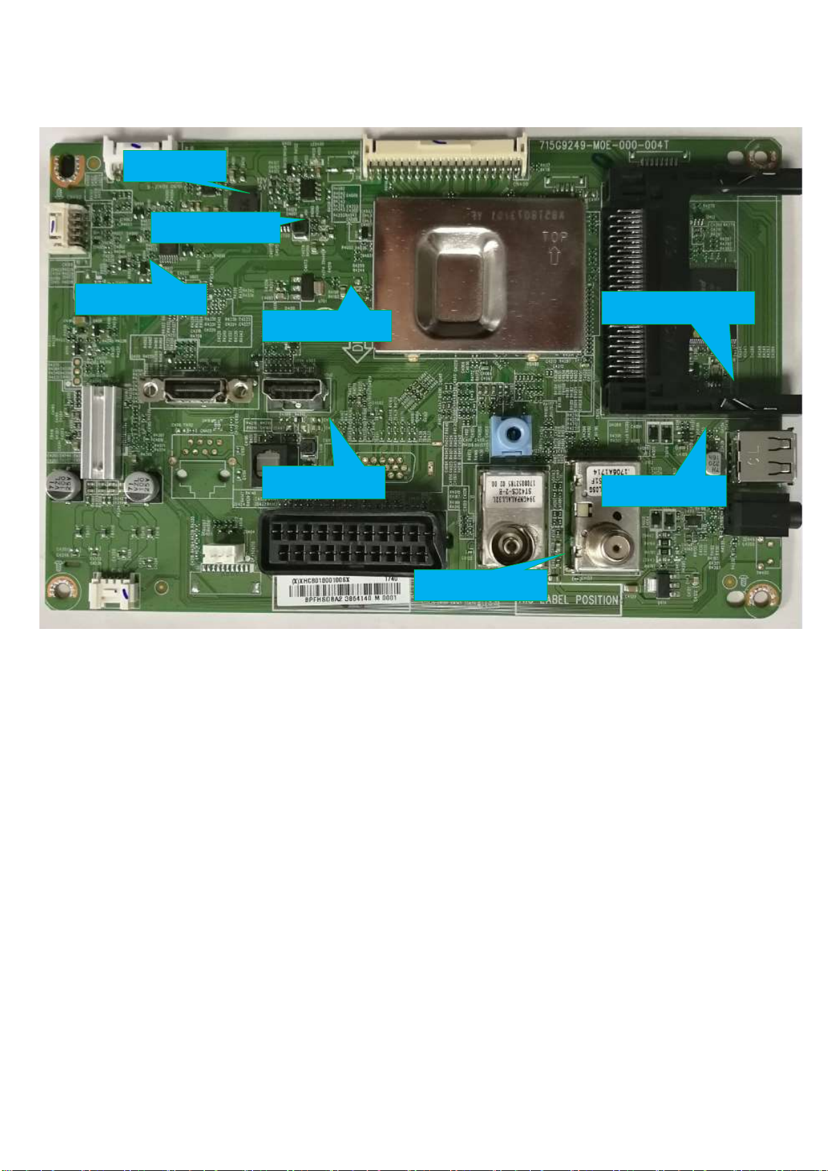
7.4 Power layout SSB
L402 +5V_SB
L401 +1.1V_VDDC
Q410 +5V_Normal
C4092 +1.5V_DDR
C4163 +3.3V_SB
Power SSB Top View
R4097 +3.3V_Normal
C4103 +5V_USB
FB412 +3.3V_TUN
Page 32
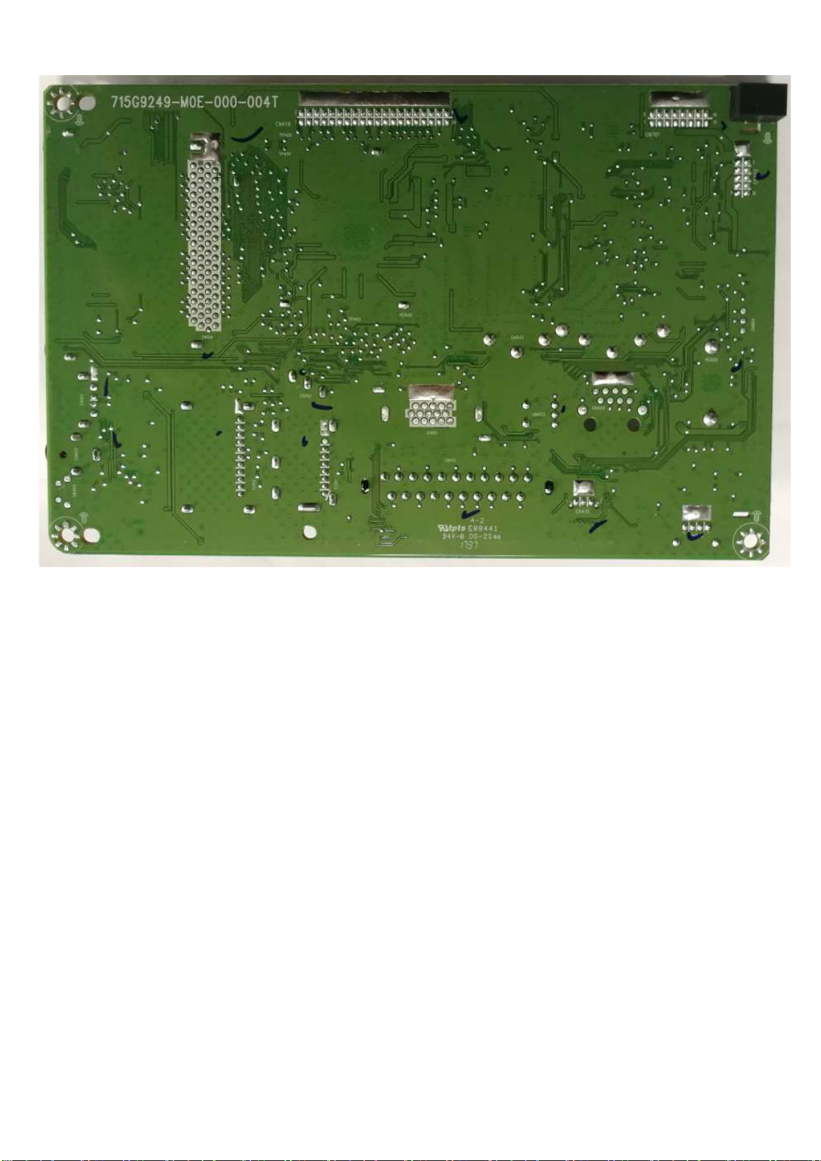
Power SSB Bottom View
Page 33
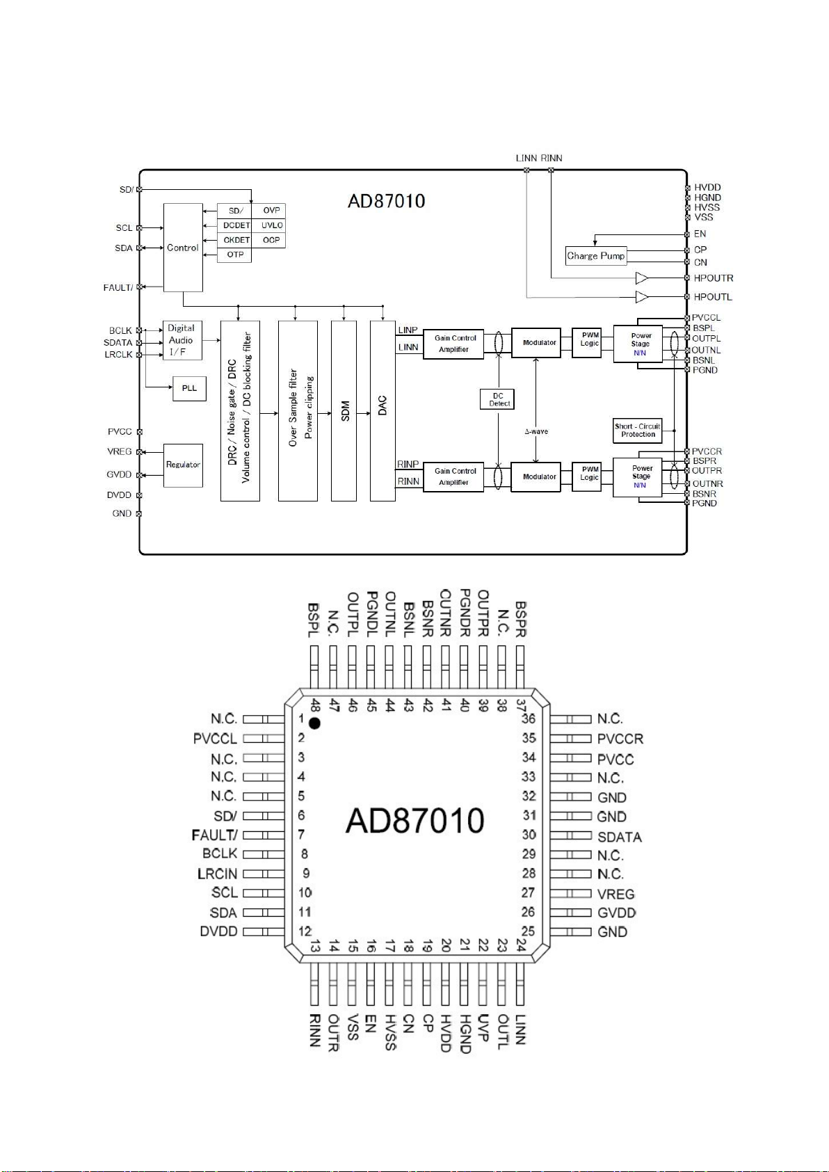
8. IC Data Sheets
8.1 AD87010-LG48NRY (IC U601)
Page 34
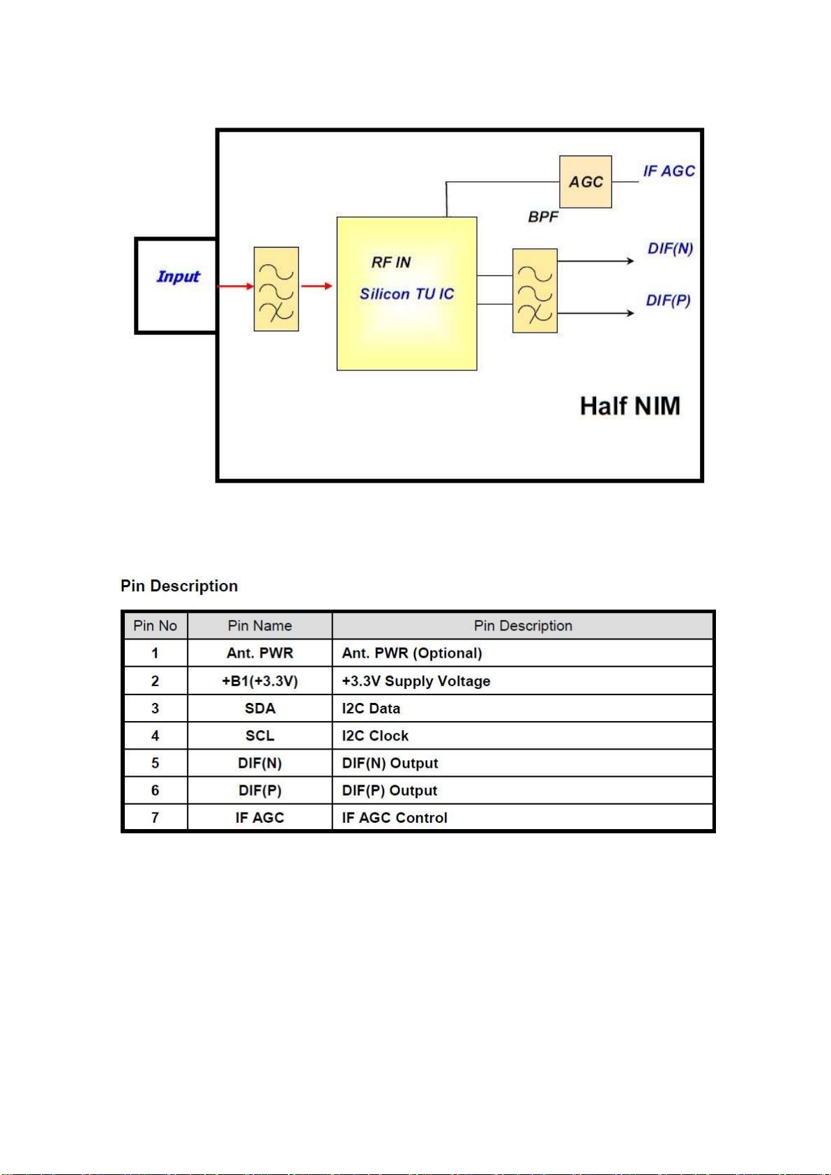
8.2 TDSY-G430D (TU101)
Page 35
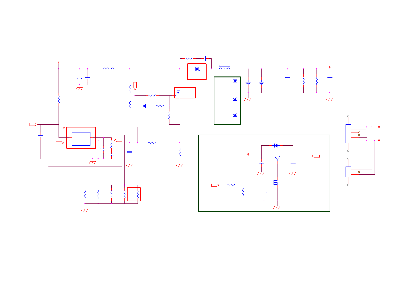
9.Circuit Diagrams
9.1 A 715G7734 PSU (For 32” 5603 Series)
9-1-1 POWER
Vcc2
C8602
220nF50V
OUT
+18V
330UF 35V
R8602
NC
LED-
C8601
U8601
PF7708BS
1
LED
2
VCC
3
CS/OVP
OUT4GND
+
FB
GM
DIM
C8606
1NF
C8605
0.1uF 50V
8
7
6
5
L8602
47uH
0 OHM +-5% 1/ 8W
C8607
220pF 50V
62K 1/8W 1%
R8616
R8617
DIM
R8603
33K 1/8W 5%
C8603
47nF 50V
OUT
Q8601: 357G0763100601 or
357G0763100605
R8604
33R 1/ 8W 5%
D8603
IN4148W RHG
C8610
22pF 50V
R8609
10R 1/ 8W 5%
R8608
4.7KOH M +-1% 1/8W
R8615
22K 1/4W
1 2
Q8601
AOD2922
R8647
10K OHM +-5% 1/ 8W
R8601
0R05
C8617
100PF 500V
1 2
D8601
SR506
Add ON/OFF Function
FB8605
BEAD
D8602
1N4148
ZD8601
BZT52-B18
ZD8602
BZT52-B18
+
1 2
Add OVP Function
1 2
+12V
VLED+
NC/ 220uF 50V
220uF 50V
C8612
+
C8616
D8604
IN4148W RHG
C8604
0.47UF 50V
C8621
0.1uF 50V
Q8603
DTA144WN3/S
R8612
100K
C8611
0.47UF 50V
R8611
NC
C8623
NC
Vcc2
78
45
CN8602
CONN
1
2
3
4
5
6
CN8601
NC/ CONN
1
2
3
VLED+
LED-
R8652
1.2R 1%
R8653
1.2R 1%
R8654
1.2R 1%
R8655
1.2R 1%
R8656
1.5R 1%
R8656:
惠璶跑
BOM1.5R
ON/OF F
R8605
1K 1/8W
R8606
330K 1/8W 5%
C8609
0.1uF 50V
Q8602
2N7002K
Page 36
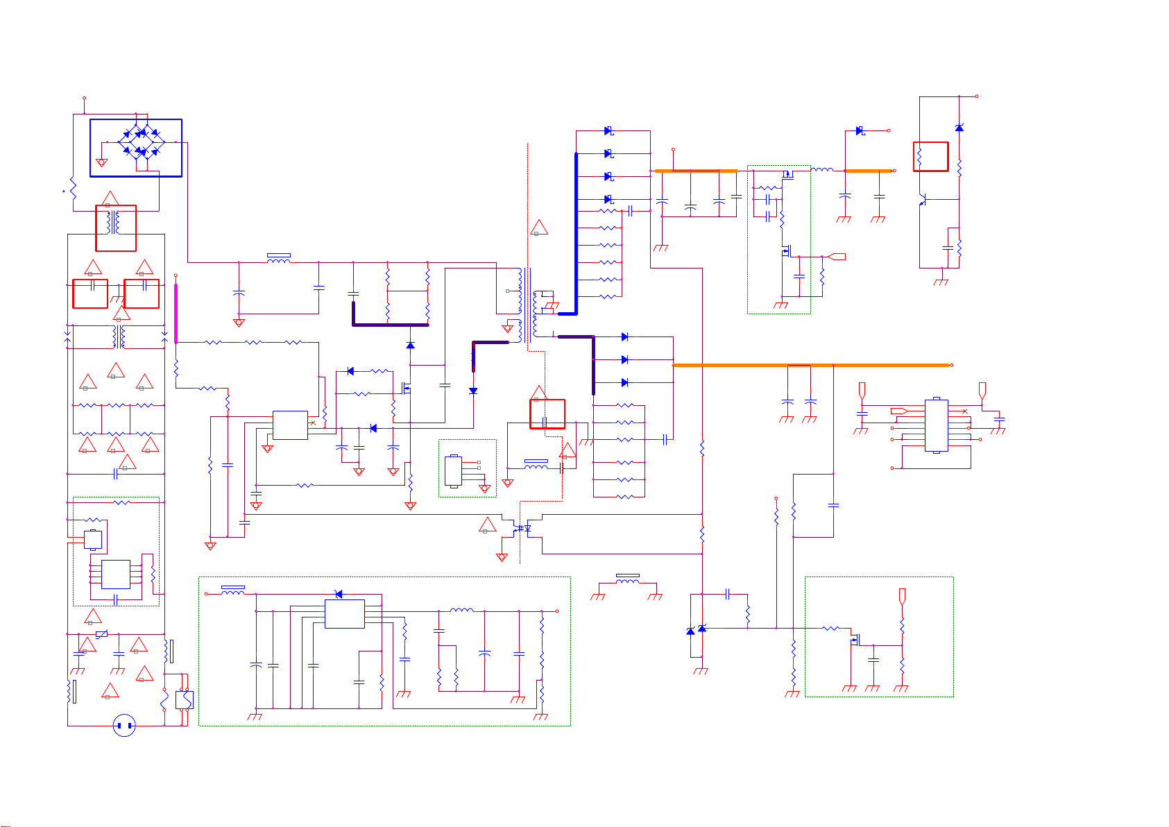
9-1-2 LED DRIVER
1
2
T4AH/250V
A
BD9901
NC/KBJ 608G-FUC
4
12
NR9901
2.5R
t
!
3
L9903
4mH
C9903
1000PF 250V
3
SG9902 SG9901
L9901
18MH
!
! !
R9903
620K +-1% 1/4W
R9905
620K +-1% 1/4W
R9904
620K +-1% 1/4W
R9906
620K +-1% 1/4W
!
C9901
470nF 275V
R9909
CN9902
2
NC/C ONN
N
1
JUMPER
L
U9901
1
NC
2
D1
3
D1
NC4NC
NC/C AP004DG-TL
C9906
NC/47pF
!
RV9901 680V
C9907
100PF 250V
FB9901
!
127R
CN9901
AC 2P
4
-
124
1000PF 250V
!
124
!
R9907
NC
D2
D2
C9910
100PF 250V
BD9902
3
3
GBL408-C
+
2
2
!!
C9902
NCNC
R9901
620K +-1% 1/4W
R9902
620K +-1% 1/4W
!!
8
7
6
5
R9908
!!
!
F9901
NC/T4AL 250V
12
1
1
+
A
R9127
3.3M 1/4W
R9114
110K
100uF 450V
R9112
510K 1/4W
R9128
3.3M 1/4W
C9801
+
R9102
510K 1/4W
R9142
3.3M 1/4W
C9125
1NF
NC
FB9301
1 2
NC/BEAD
+12VS
12
FB9902
127R
3 4
F9902
1 2
C9331
NC/470U F 25V
FB9908
BEAD
1 2
1
BNO
2
FB
3
CS
GND4OUT
C9106
330PF 50V
C9124
1NF
+
R9103
510K 1/4W
U9101
VCC
NC
VCC
PF6005AS
R9113
1K 1/4W
C9336
NC/220N 50V
C9113
2.2NF
8
7
6
5
C9102
2.2UF 50V
1
2
3
U9301
NC/AOZ 3015AI
C9334
NC/100N 50V
NC/1N 50V
D9104
IN4148W
R9110
47R 1%
R9146
0 OHM +-5% 1/8W
+
ZD9301
NC/BZ T52-B5V1
12
PGND
EN
VIN
LX
AGND
COMP
VCC4FB
C9330
C9103
2.2NF
R9109
10R 1/8W 5%
D9106
IN4148W
C9104
0.1uF 50V
8
7
6
5
NC/3K OHM 1%
R9344
R9104
82K OHM 1%
R9105
82K OHM 1%
D9103
FR107G-A0
Q9101
TK6A65D(STA4,X,M)
R9111
10K OHM +-5% 1/8W
+
C9105
10UF50V
R9101
0.27R 2W
R9345
NC/20K 1%
C9333
NC/2N 2 50V
R9358
NC/30R 1/4W
R9106
82K OHM 1%
R9107
82K OHM 1%
C9126
NC/100PF
For Q9101
HS9101
HEAT SINK
C9335
NC/2N 2 50V
L9301
1
2
3
4
R9361
NC/30R
R9108
4R7 1/4W 5%
D9105
PR1007G
!
U9102
EL817M(X)
+
HOT COLD
5
3
4
2
1
1 2
4
C9332
NC470UF 25V
!
T9101
POWER X'FMR
!
C9904
1NF 250V
FB9906
NC
1
23
C9323
NC/220N 50V
+18V
L9101
3UH
R9307
NC/270K +-1% 1/8W
330UF 35V
C9116
+
1nF 50V
R9144
NC/8. 2K 1/8W
D9109
SR34H
1 2
+
C9111
470UF 25V
PS_ON
C9127
C9129
NC
DIM
PS_ON
+12V_A
+5.2V
Q9106
NC/2N 7002K
NC/1N 50V
C9112
0.1uF 50V
+12V
C9140
+12V_A
+12V
PS_ON
R9130
1K OHM
Q9102
2N3904
C9119
0.1uF 50V
CN9101
CONN
1
3
5
7
9
11
13
15
R9143
NC/100K 1/8W 1%
R9145
NC/100K 1/8W 1%
+18V
ZD9101
BZT52-B22
1 2
470OHM +-5% 1/ 8W
R9129
R9131
1K 1/8W
ON/OFF
2
4
6
8
C9128
10
1nF 50V
12
+12V_A
14
16
+12V
D9110
SR510-22
1 2
D9111
SR510-22
1 2
D9112
SR510-22
1 2
D9101
SR510-22
1 2
R9115
22 OHM 1/4W
R9116
22 OHM 1/4W
R9148
22 OHM 1/4W
R9149
22 OHM 1/4W
R9117
8
NC
9
R9150
6
NC
7
10
!
C9908
NC
+5.2V
R9348
NC/10. 5K
R9342
NC/200R
R9347
NC/2K
R9120
22 OHM 1/4W
R9140
22 OHM 1/4W
R9138
22 OHM 1/4W
R9118
NC
R9119
NC
R9139
NC
1 2
D9102
SR515
D9107
SR515
D9108
SR515
FB9302
BEAD
C9107
3.3NF 500V
+12VS
C9121
470uF 25V
+
C9108
470pF 1KV
ZD9104
BZT52-B16G
NC/470uF 25V
C9109
470uF 25V
+
1 2
C9101
C9110
0.1uF 50V
+
R9121
2K4 1/8W 5%
R9122
9.1K OHM
C9117
220nF50V
U9103
TL431G-AE2-R
R9302
NC/100K 1 /8W
C9307
NC/1uF
C9308
NC/1uF
NC/100N 50V
R9123
43K 1/8W 1%
10K OHM +-5% 1/8W
R9124
9.31K +-1% 1/8W
680R 1/8W 1%
Q9306
NC/P1604ED
C9306
+12VS
R9126
R9141
JUMPER
R9304
NC/100K 1 /8W
Q9305
NC/2N 7002K
NC
330UF 35V
C9122
+
R9125
620K 1/8W 1%
Page 37
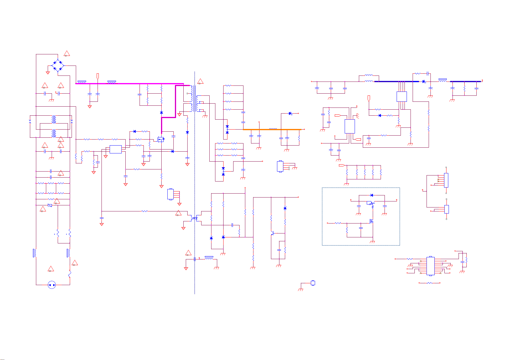
9.2 A 715G7735 PSU (For 24” 5603 Series)
9-2-1 POWER
!
2
BD9901
36W: BD9901 093G 50460518
KBP208G-C
45W: BD9901 393G0050460A02
+
-
L9902
NC/23mH
3
124
L9901
30MH
C9901
470nF 275V
!
3
A
124
3
100PF 250V
!
12
t
12
C9906
330PF 250V
!
!
C9904
绢仅
!
R9901
NC/750K +-5% 1/ 4W
R9906
NC/750K +-5% 1/ 4W
NR9902
NC/5R
1
1 2
SG9901
DSPL-501N-A21F
R9135
3M3 1%
for cost
12
NR9901
5R
t
12
FB9908
BEAD
!
T2.5AL/250V
F9901
2.5A 250V
FB9906
127R
C9801
47UF 450V
510K +-1% 1/4W
100K 1/8W 1%
R9104
R9102
3M3 1%
R9114
3M3 1%
R9103
+
B+
1 2
+
C9802
NC_47UF 45 0V
R9134
510K +-1% 1/4W
C9109
1nF 50V
C9119
2.2nF 50V
FB9905
BEAD
1
2
C9102
2.2NF
R9111
D9103
47R 1%
1N4148W
R9106
510K +-1% 1/4W
GND
FB
BNO3CS
IC9101
PF6005AG
OUT
VCC
R9112
47R 1%
6
5
R9113
4
0 OHM +-5% 1/8W C8603
C9104
0.1uF 50V
R9115
470OHM +-5% 1/8W
C9105
220pF 50V
R9144
0R05 1/4W
SG9902
DSPL-501N-A21F
R9903
NC/750K +-5% 1/ 4W
R9904
NC/750K +-5% 1/ 4W
12
FB9907
BEAD
4
! !
C9907
330PF 250V
!
C9903
100PF 250V
C9902 NC/ 470NF 305V
R9905
NC/750K +-5% 1/ 4W
R9902
NC/750K +-5% 1/ 4W
R9907
1M5
RV9901
!
680V
CN9901
AC 2P
R9107
82K OHM 1%
R9109
82K OHM 1%
D9105
FR107G-A0
2
1
R9121
10K OHM +-5% 1/8W
3
+
C9103
4.7uF 50V
Hot
R9108
82K OHM 1%
R9110
82K OHM 1%
Q9101
IPA65R1K5CE
D9104
1N4148W
R9101
0.33 OHM 2W
HS9101
HEAT SINK
R9105
4R7 1/4W 5%
C9100
100PF
C9106
4.7uF 50V
1
2
3
4
!
IC9102
EL817M(X)
Hot
6
5
4
1
2
D9106
1N4007GHA0G
+
4
!
680PF 250V
C9905
!
T9101
POWER X'FMR
11
8
7
10
9
R9125
680R 1/8W 1%
1
23
ZD9101
BZT52-B13G
FB9901
BEAD
A
1 2
Cold
Cold
R9129
30 OHM 1/4W
R9116
30 OHM 1/4W
R9130
30 OHM 1/4W
R9119
30 OHM 1/4W
3
1
R9117 33ohm 1/ 4W +/-5%
R9118 33ohm 1/ 4W +/-5%
R9139 33ohm 1/ 4W +/-5%
3
D9107
2
FMXA-2202S
1
R9127
NC/100K 1/ 8W 1%
R9128
1K5 +-1% 1/8W
IC9103
AS431AN-E1
1 2
D9101
2
FMEN-220A
470UF 25V
R9140 33ohm 1/ 4W +/-5%
R9141 33ohm 1/ 4W +/-5%
R9142 33ohm 1/ 4W +/-5%
R9120
22K 1/8W 1%
C9112
220nF50V
R9123
10K OHM +-5% 1/8W
C9117
+
+12V1
C9114
1NF 500V
C9107
1NF 500V
C9113
1NF 500V
C9115
330UF 35V
+12V1
+
R9124
390K 1/8W 1%
R9126
5K1 1/8W 1%
R9131
0 OHM +-5% 1/8W
C9118
+
470UF 25V
+24V_AL
2N3904
Q9102
L9101
3UH
C9108
0.1uF 50V
R9136
470R 5%
C9121
0.1uF 50V
D9108
NC_SR204
1 2
HS9102
NC_HEAT SIN K
1
2
3
4
1 2
+12V_Audio
C9111
+
R9122
270UF 25V
12K 5% 1/4W
+24V_AL
ZD9102
BZT52-B33
R9138
470 OHM 1/4W
R9137
1K OHM +-5% 1/8W
+24V_AL
36W: L8601 373G0253214X02
45W: L8602 073G 253214 X
L8601
NC/47UH
L8602
+
C8601
C8604
C8613
0.1uF 50V
R8613
100KOHM +-5% 1/8W
FB
C8607
10nF 50V
+
0.47UF 50V
FB
秨诀
R8615
0.1uF 50V
LED1VCC2CS/OVP3OUT
+12V1
R8616
330K 1/8W 5%
330UF 35V
C8606
10nF 50V
+12V
VLED-
Vcc2
C8608
10UF 50V
For
ON/OFF
1K OHM +-5% 1/8W
GND3
1
NC/GND
47UH
OUT
DIM
5
6GM7FB8
DIM
GND
IC8601
PF7708BS
4
OUT
22pF 50V
R8606
4.7R 1%
R8609
4.7R 1%
R8611
4.7R 1%
D8604
1N4148W
2 3
C8611
0.1uF 50V
C8612
0.1uF 50V
R8601
56R 1/8W 5%
D8602
1N4148W
C8609
R8614
4.7R 1%
Q8602
DTA144WN3/S
1
Q8603
2N7002K
SM1A30NSK
10ohm +/-1% 1/8W
R8608
2K7 1/4W 1%
R8610
NC_2R2 1%
Q8601
R8602
C8610
0.1uF 50V
ON/OFF
Vcc2
+12V_Audio
5
4
R8603
10K 1/8W
+12V
R8612
NC/22K 1%
D8D7D6D
S1S2S3G
R9143
0R +-5% 1/8W
R8604
0.18R
+12V
D8601
SR510-22
1 2
VLED-
C8605
NC/100PF 500V
R8607
30K
R8605
27Kohm 1/4W +/ -1%
VLED+
VLED+
CN9101
CONN
15
13
11
9
7
5
3
1
R9145
0R05 1/4W
100UF 63V
+
FB9903
BEAD
1 2
C8602
6
5
4
3
2
1
3
2
1
16
14
12
10
8
6
4
2
+12V_Audio
7 8
4 5
PS_ON
CN8604
NC/CON N
CN8605
CONN
DIM
+12V_Audio
+12V
+
C8615
NC_47uF 100V
For 32
For 21.5 /23.5
ㄏノ
C9120
100PF 50V
R8617
200K 1/8W 5%
ㄏノ
R9132
NC/0 OH M +-5% 1/8W
VLED+
C8614
0.1uF 100V
Page 38
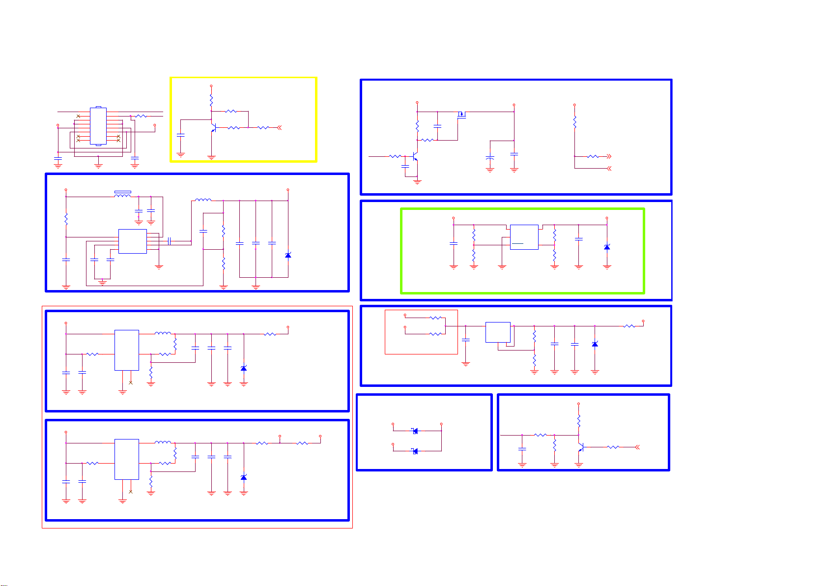
9.3 B 715G9249 SSB
9-3-1 System Power
MAIN POWER
CN701
CONN
16
BL-ON/OFF
+12V_AUD
C4156
100NF 25V
+12V_Normal
R4094
100K 1%
C4090
1UF 25V
15
14
13
11
9
7
5
3
1
FB410
1 2
120R 6A
U702
1
EN
2
FB
3
VREG5
SS4GND
C4087
RT6206BHGSP
8.2NF 50V
R4086
100R
12
10
8
6
4
2
C4086
1UF 25V
BL-ADJUST
+12V_Normal
C4157
100pF 50V
C4080
GND
VIN
BOOT
SW
STANDBY
C4081
9
8
7
6
5
BL-ADJUST
NC/2. 2UF 6.3V
12V TO 5VSB
Vo ut=0.765x (1 +124K/21.5K) = 5.17V
10UF 16V
100NF 25V
C4082
100NF 16V
+3.3V_Standby
R4084
NC/2. 2K1/16W
Q406
NC/LMBT3904LT1G
C4072
L402
3.3uH
C4088
22pF 50V
Inverter controler
R4085
0R05 OHM
R4087
3
NC/0R 05 OHM
1
R4095
124K 1%
R4098
22K 1%
R4088 1K
C4083
100NF 16V
C4084
22UF 10V
2
+5V_Standby
C4085
22UF 10V
BRI_ADJ 4
ZD417
NC/MM1Z5B6
1 2
5V STANDBY TO 5V NORMAL
+5V_Standby
Q410
MTP2317N3
+5V_Normal
R4096
1K 1/16W
C4089
1UF 10V
R4099
100K 1/16W 5%
G9141T11U 600mA:056G 563156 3.37=1.0(1+(23. 7K/10K))
9/29 R704
47K to 6.8K
for Vbe
STANDBY
R4102
C4094
10K
100NF 16V
R4104
100K
R4105
Q401
LMBT3904LT1G
C4098
10K
NC/4. 7UF 10% 10V
AO3401A=057G 763940 =4.3A
MTP2317N3=357G0763020005 =5.8A
TPV: U602 c hange to G9141 b ased on SoC curre nt consumption S PEC 12/26
+5V_Normal
C4096
+
NC/100UF 16V
1
2
C4097
NC/10U F 16V
U703
G9141T11U SOT23-5
IN
OUT
GND
SHDN3SET
POWER Controller
+3.3V_Standby
R4109
4.7K 1/16W
R4112
0R05 OHM
5
R4097
C4091
23.7K 1%
4
R4100
10K 1% 1/16W
4.7UF 10% 10V
"PW R_ON"
Norma l:High
Sta ndby:LOW
STANDBY
PWR_ON/ OFF
+3.3V_Normal
ZD418
NC/BZ T52-B3V6S
1 2
14
4
+5V_Standby
1.15V 2A for VDDC
U700
C4075
NC/1uF 10V
R4211
4K7 1/16W 5%
C4077
2.2UF 16V
4
1
G5719TBIU
3
VIN
LX
6
EN
VFB
GND2NC
R4093
20K 1%
5
L401
2.2uH
R4209
0R05 1/16W
Vo=0.6x(1+R1/R2)=0.6((18/20)+1) = 1.14V
+5V_Standby
3.3V 2A for 3V3_STB
C4162
NC/1uF 10V
4K7 1/16W 5%
C4161
2.2UF 16V
4
1
G5719TBIU
U704
VIN
EN
GND2NC
L408
3
LX
2.2uH
6
R4216
VFB
0R05 1/16W
R4214
20K 1%
5
Vo=0.6x(1+R1/R2)=0.6((91/20)+1) = 3.33V
R1
R2
R1
R2
R4090
17.4K 1%
R4215
91K 1%
C4078
NC/100N 16V
C4160
NC/100N 16VR4213
C4073
22UF 6. 3V
C4163
22UF 6. 3V
R4210
0 OHM 1/8W
max loading < 800mA
C4074
NC/10U F 6.3V 20%
ZD449
NC/MMSZ4678
1 2
+3.3V_Standby
R4212
0 OHM 1/8W
max loading < 300mA
C4164
NC/10U F 6.3V 20%
ZD447
NC/BZ T52-B3V6
1 2
VDDC
+3.3V_Normal
R4089
NC/0R 05 OHM
+3.3V_Normal
+3.3V_Standby
R4206
NC/0R 05 1/10W
R4207
0R05 1/10W
C4095
10UF 10V
Max. Curre nt Consumption
DTV mode: 200mA
For AC OFF USB UPDATE CODE
+5V_Standby
+5V_Normal
D4009
FB340M
D4010
FB340M
+5V_USB
12
12
+1.5V Power for DDR3
U701
AZ1117H-ADJ -E1 SOT223
2
VI3VO
GND14
R4103
10K 1%
R1
4
R4106
1.3K 1%
R2
1.4125V=1 .25 * ( 1+1K3/10K )
BL-ON/OFF
R4108
100R 1/16W 5%
C4099
1NF
C4093
C4092
100NF 16V
22UF 6. 3V
+5V_Standby
R4110
8K2 1/16W +/-5%
ZD448
NC/MMSZ4678
1 2
R4107
4K7 1/16W 5%
Q404
MMBT3904
R4101
0R05 OHM
R4111
4K7 1/16W 5%
+1.5V_DDR
Bac k Li gh t On / O ff
HI => PO WER _OF F
LO => PO WER _ON
VBL_CTRL
4
Page 39
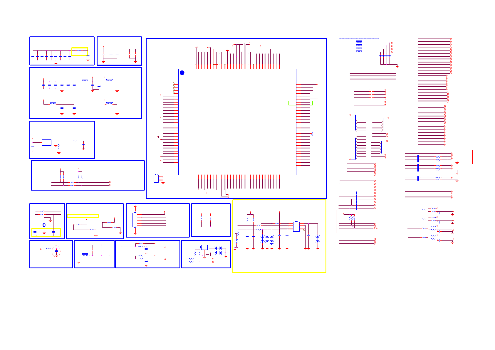
9-3-2 MSD92LGSW2
SPI NOR FLASH
CORE POWER
VDDC
C4005
C4006
C4009
C4008
C4010
C4007
100NF 25V
2.2UF 6.3V
100NF 25V
Standby Power 3.3V
+3.3V_Standby
2.2UF 6.3V
+3.3V_Standby
RESET (H Reset)
+3.3V_Standby
3
C4037
100NF 16V
I2C Bus
Crystal
垂砰熬惠
R4022
22 OHM 1/16W
R4026
1M 1%
1243
C4058
18PF 50V
SPDIF OUT
4,7
SPDIF_OUT
100NF 25V
100NF 25V
100NF 25V
C4018
C4019
100NF 25V
100NF 25V
FB407
1 2
120R
U411
G690H293T7 3
2
RESET
Vcc
1
GND
M_SCL
M_SDA
X400
24MHZ
C4059
18PF 50V
R4050
100OHM
Close to MSTAR IC
100NF 25V
C4020
RESET
+3.3V_Normal
R4013
30PPM
XTALO
XTALI
C4011
C4012
100NF 25V
C4021
100NF 25V
100NF 25V
C4035
100NF 25V
R4003
100K 1/16W 5%
R4014
NC/4.7K 1/ 16W
NC/4.7K 1/ 16W
SPDIF-OUT
C4065
33P 50V
DVDD_DDR
R4000
0R05 OHM
can't delete
C4014
C4013
100NF 25V
22UF 6.3V
AVDD_MOD1
FB405
1 2
120R
C4027
C4022
100NF 25V
AVDD_AU33
C4036
100NF 25V
Close Sca ler
R4002
100R 1/16W 5%
R4019
0R05 1/16W
R4020
0R05 1/16W
CHIP_CONFIG [1:0]
{PAD_PWM1, PAD_PWM0}
2'b01 Boot from SPI_NOR Flash
2'b10 Boot from ROM
C4023
100NF 25V
System -RST
System -RST
C4038
100NF 16V
+3.3V_Normal
R4015
R4016
4.7K 1/16W
4.7K 1/16W
IC Configuration Sele ction
+3.3V_Standby
R4039
1K
PWM1/13/18V_SW
R4043
NC/10K
C4066
L400
100NF 25V
12
1000 OHM
Close to MSTAR IC
with width trace
DDR3 POWER
+1.5V_DDR
C4000
2.2UF 6. 3V
+3.3V_Standby
1 2
C4024
22UF 6.3V
+3.3V_Standby
1 2
M-SCL
M-SDA
BRI_ADJ-PWM0
AUVAG
C4067
10UF 6.3V 20%
AUVRM
100NF 25V
FB406
120R
FB408
120R
C4001
M-SCL
M-SDA
+3.3V_Standby
R4036
NC/10K
C4002
100NF 25V
AVDD_DMPLL
C4025
100NF 25V
AVDD_DADC
C4034
100NF 25V
R4042
1K
IF AGC
5,9,10
5,9,10
IFAGC-T
IFAGC-S
C4003
100NF 25V
C4004
2.2UF 6.3V
+3.3V_Standby
for Rea r
HDMI 2
CN502
CEC
VGA-->
+3.3V_Standby
SCART-->
GPIO-->
VGA
Audio IN -->
SCART / BT
Audio IN-->
HOTEL
Audio OU T-->
HP
Audio Out-->
AVDD_DADC
Shielding Cover
X85T 804210100 000LH
MIPS E -JTAG # 3
CN403
910
1
2
3
4
5
EDINTP PC M_A12
6
ETDOP PCM_D5
7
EJTAG_RST_N PCM_RESET
8
ETMSP PCM_A6
NC/CONN
R4051
10K
R4053
C4068
0R05 OHM
22NF 25V
R4052
10K
R4054
C4069
0R05 OHM
22NF 25V
TPV:E-Pad
connect to GND 1
2/26
IC
U401
MSD92LGSW2
HDMI2_CLKN
HDMI2_CLKP
HDMI2_RX0N
HDMI2_RX0P
HDMI2_RX1N
HDMI2_RX1P
HDMI2_RX2N
HDMI2_RX2P
VGA_HS
BIN0
GIN0P
GIN0M
RIN0
VGA_VS
BIN2
GIN2P
GIN2M
RIN2
SCART-FB
BATH-AMP-EN
BT-EN
AMP-MUTE
ARC-DEC
CVBS0
VCOM0
CVBS_OUT0
VDDC
AVDD_AU33
AUVRM
AUVAG
VGA-LIN
VGA-RIN
AUL4
AUR4
AUOUT_L0
AUOUT_R0
AMP-INL
AMP-INR
AVDD_AU33
QP_S
QM_S
IP_S
IM_S
HS400
1
2
3
4
SHIELD
+3.3V_Standby
ETCKPPCM_D4
ETRSTNPC M_D7
ETDIPPCM_D6
+3.3V_TU
IFAGC_T
+3.3V_TU
IFAGC_S
for Re ar
HDMI 1
CN501
CEC
ARC
1
RXCN_B
2
RXCP_B
3
RX0N_B
4
RX0P_B
5
RX1N_B
6
RX1P_B
7
RX2N_B
8
RX2P_B
9
AVDD_MOD
10
RXCN_A
11
RXCP_A
12
RX0N_A
13
RX0P_A
14
RX1N_A
15
RX1P_A
16
RX2N_A
17
RX2P_A
18
HSYNC0
19
BIN0P
20
GIN0P
21
GIN0M
22
RIN0P
23
VSYNC0
24
AVDD33_ADC
25
BIN1P
26
GIN1P
27
GIN1M
28
RIN1P
29
VSYNC1
30
BIN2P
31
GIN2P
32
GIN2M
33
RIN2P
34
CVBS0
35
VCOM
36
CVBS_OUT
37
VDDC
38
AVDD33_AU
39
VRM
40
VAG
41
LINEIN_L2
42
LINEIN_R2
43
LINEIN_L3
44
LINEIN_R3
45
LINEOUTL3
46
LINEOUTR3
47
EARPHONE_OUTL
48
EARPHONE_OUTR
49
AVDD33_EAR
50
QP_S
51
QM_S
52
AVDD33_DADC
53
IP_S
54
IM_S
9
9
VDDC
HDMI1_RX0N
HDMI1_CLKP
HDMI1_CLKN
HDMI1_RX0P
HDMI1_RX2P
HDMI1_RX2N
HDMI1_RX1P
HDMI1_RX1N
217
216
215
214
213
212
211
210
209
218
GND
EPAD
RX2P_D
RX1P_D
RX0P_D
RX2N_D
RX1N_D
RX0N_D
RXCP_D
IFAGC_S55IFAGC_T56IP_T57IM_T58AVDD33_DMPLL59XIN60XOUT61VDDC62GPIO4463GPIO4564GPIO46/TX265GPIO48/I2S_OUT_SD67VDDIO_CMD69VDDC70AVDD_MOD73PCM_RESET/EJ _RSTZ74PCM_IRQA_N75PCM_CD_N76PCM_REG_N77PCM_CE_N78PCM_OE_N79PCM_WE_N80PCM_WAIT_N81PCM_IORD_N82PCM_IOWR_N83PCM_D084PCM_D185PCM_D286PCM_D3
XTALI
XTALO
VIFM
IFAGC-T
VIFP
IFAGC-S
AVDD_DMPLL
VDDC
LED
+5V_Normal
R4028
NC/4.7K 1/ 16W
R4057
100OHM
R4058
100OHM
+5V_Standby
CN410
CONN
123
R40564.7K 1/16W
R40554.7K 1/16W
DEBUG
UART_TX
UART_RX
HDMI1_HPD IN
AMP_PDN
HDMI2_SCL
HDMI2_HPD IN
ARC
HDMI_C EC
208
207
206
205
204
203
202
201
ARC
CEC
RXCN_D
AVDD_5V
HOTPLUG_A
HOTPLUG_B
HOTPLUG_D
VDDC/AVDD L_DVI
GPIO47/I2S_OUT_W S66GPIO49/DISEQC
68
M_SCL
M_SDA
I2S-WS
PWR_ON/OFF
DISEQC
I2S-SDO
+5V_Standby
R4029
NC/4.7K1/16W
LED_B
MUST pull high to 5VSTB
ISP AND VGA EDID
ZD404
1 2
ZD405
1 2
AZ5125-01H.R7G
AZ5125-01H.R7G
UART-TX
UART-RX
+1.5V_DDR
+3.3V_Standby
HDMI2_SDA
197
199
198
200
DDCDB_CLK
DDCDA_CLK
DDCDB_DAT
DDCDA_DAT
GPIO50/I2S_OUT_BC K
GPIO51/I2S_OUT_M CK
71
72
I2S-MCK
I2S-BCK
6,8,14
6,8,14
MDI_TP
MDI_TN
GND
PCM_CD_N
PCM_IRQA_N
PCM_RESET
+3.3V_Standby
VDDC
+1.5V_DDR
MDI_RN
MDI_RP
192RN193TP196TN195RP194
PCM_OE_N
PCM_CE_N
PCM_REG_N
191
187
186
188
189
190
GND
VDDIO_DATA
VDDIO_DATA
AVDD33_ETH
VDDIO_DRAM
VDDIO_DRAM
PCM_WAIT_N
PCM_WE_N
PCM_D1
PCM_D0
PCM_IOWR_N
PCM_IORD_N
IR&KEYB
IRIN
KEY0_IN
R4046
0R05 1/16W
4
SW400
SW
123
EMI & ESD solution
EMI & ESD solution
AVDD_MOD1
DVDD_DDR
SCART-FS
KEY0_IN
HDMI1_SCL
HDMI1_SDA
185
184
183
180
181
182
SAR1
SAR0
MHL_DET
AVDD_MOD
DDCDD_C LK
DDCDD_SD A
DVDD_DDR _DATA
PCM_D4/EJ_T CK88PCM_D5/EJ_T DO89PCM_D6/EJ_T DI90PCM_D7/EJ_T RSTN91PCM_A1492PCM_A1393PCM_A12/EJ_DI NT94PCM_A1195PCM_A1096PCM_A997PCM_A898PCM_A799PCM_A6/EJ_TM S
87
PCM_D3
PCM_D2
PCM_D7
PCM_D6
PCM_D5
PCM_D4
+3.3V_Standby
R4027
R4023
3.9K 1%
10K 1% 1/16W
C4062
C4063
100pF 50V
100pF 50V
NAND-RBZ
UART_TX
UART_RX
179
178
177
176
VDDC
DDCA_CK
DDCA_DA
PCM_A14
PCM_A11
PCM_A12
PCM_A13
R4038
100OHM
R4040
100R 1/16W 1%
VDDC
NAND-WEZ
NAND-ALE
NAND-WP
175
173
174
SPI-NAND_WP/ NAND_WP
SPI_CK/SPI-NAN D_CK/NAND _ALE
SPI_DO/SPI-NAN D_DO/NAN AD_RBZ
PCM_A9
PCM_A10
PCM_A8
LED_R
IR_RC
12
ZD400
AZ5125-01H.R7G
AZ5125-01H.R7G
AZ5125-01H.R7G
RC is for EMI
FB400 120R
1 2
I2S-MCK
FB401 120R
I2S-BCK
FB403 120R
I2S-WS
FB404 120R
I2S-SDO
All I2S trace need to shield GND
PWM1/13/18V_SW
NAND-REZ
BRI_ADJ-PWM0
System-RST
NAND-CLE
NAND-CEZ
IRIN
SPDIF-OUT
BT_LED
169
168
167
166
165
172
164
163
171
170
IRIN
VDDC
PWM1
PWM0
RESET
GPIO2/RX2
NAND_CLE
GPIO0/SPDIF_OUT
SPI-NAND_HOLDN /NAND _WEZ
SPI_DI/SPI-N AND_DI/NA ND_REZ
SPI_CS/SPI-NAND _CS/NAND _CEZ
PCM_A0
PCM_A5
PCM_A4
PCM_A3
PCM_A2
PCM_A1
TS0_CLK
106
100
101
102
103
104
105
108
107
PCM_A3
PCM_A4
PCM_A5
PCM_A6
PCM_A7
TS0_SYNC
TS0_CLK
PCM_A0
PCM_A1
PCM_A2
+3.3V_Standby
R4199
100R 1/16W 1%
KEY1_IN
12
12
C4061
ZD402
100NF 16V
ZD401
AVDDL_MOD/VDDC
LVACLK-/TCON2
LVACLK+/TCON3
TS0_SYNC
GPIO16
GPIO17
GPIO18
GPIO19
AVDD_MOD
LVBCLK-
LVBCLK+
LVA2-/TCON0
LVA2+/TCON1
LVA3-/TCON4
LVA3+/TCON5
LVA4-/TCON6
LVA4+/TCON7
DP_P0
DM_P0
DP_P1
DM_P1
TS1_D0
TS1_D1
TS1_D2
TS1_D3
TS1_D4
TS1_D5
TS1_D6
TS1_D7
TS1_VLD
TS1_SYNC
TS1_CLK
TS0_D0
TS0_D1
TS0_D2
TS0_D3
TS0_D4
TS0_D5
TS0_D6
TS0_D7
TS0_VLD
C4154
100pF 50V
162
161
160
159
158
157
LVB0-
156
LVB0+
155
LVB1-
154
LVB1+
153
152
LVB2-
151
LVB2+
150
149
148
LVB3-
147
LVB3+
146
LVB4-
145
LVB4+
144
LVA0-
143
LVA0+
142
LVA1-
141
LVA1+
140
139
138
137
136
135
134
133
132
131
130
129
128
127
126
125
124
123
122
121
120
119
118
117
116
115
114
113
112
111
110
109
CN402
CONN
1
3
5
7
9
LED_R
VBL_CTRL
LNB_EN
PANEL_ON/OFF
RXO0RXO0+
RXO1RXO1+
RXO2RXO2+
RXOCRXOC+
RXO3RXO3+
RXO4RXO4+
RXE0RXE0+
RXE1RXE1+
RXE2RXE2+
RXECRXEC+
RXE3RXE3+
RXE4RXE4+
USB0_DP
USB0_DM
USB1_DP
USB1_DM
2
4
6
8
10
TS1_D0
TS1_D1
TS1_D2
TS1_D3
TS1_D4
TS1_D5
TS1_D6
TS1_D7
TS1_VLD
TS1_SYNC
TS1_CLK
TS0_D0
TS0_D1
TS0_D2
TS0_D3
TS0_D4
TS0_D5
TS0_D6
TS0_D7
TS0_VLD
TP400
TP401
LED_B
C4155
100pF 50V
NC/AZ5125-01H. R7G
VDDC
+3.3V_Standby
12
ZD403
I2S
NAND-WP NAND_WP
OTHER
12
PCM_D[7:0]
12
PCM_A[14:0]
USB0_DP
USB0_DM
USB1_DP
USB1_DM
MDI_RN
MDI_RP
MDI_TN
MDI_TP
AMP-INR
AMP-INL
AUOUT_L0
AUOUT_R0
VGA-RIN
VGA-LIN
AUR4
AUL4
+3.3V_Standby
VBL_CTRL
BT_LED
PANEL_ON/OFF
AMP_PDN
LNB_EN
PWM1/13/18V_SW
IRIN
IR_RC
1 2
1 2
1 2
SPI & NAND
IP_S
IM_S
QP_S
QM_S
VIFP
VIFM
DISEQC
PWR_ON/OFF
BRI_ADJ-PWM0
Trans port Stre am
PCM_D0
PCM_D1
PCM_D2
PCM_D3
PCM_D[7:0]
PCM_D4
PCM_D5
PCM_D6
PCM_D7
PCM_A0
PCM_A1
PCM_A2
PCM_A3
PCM_A4
PCM_A5
PCM_A6
PCM_A7
PCM_A8
PCM_A9
PCM_A10
PCM_A[14:0]
PCM_A11
PCM_A12
PCM_A13
PCM_A14
C4050
2.2UF 16V
C4051
2.2UF 16V
C4052
NC/2.2UF 16V
C4053
NC/2.2UF 16V
C4054
2.2UF 6.3V
C4055
2.2UF 6.3V
R4030 4.7K 1/16W
R4031 4.7K 1/16W
R4033 NC/4.7K 1/16W
R4348 NC/4.7K1/16W
I2S_MCLK
I2S_SCLK
I2S_LRCLK
I2S_SD0
100NF 25V
C4028
C4029 100NF 25V
C4030
100NF 25V
C4031
100NF 25V
100NF 25V
C4032
C4033
100NF 25V
TS1_D0
TS1_D1
TS1_D2
TS1_D3
TS1_D4
TS1_D5
TS1_D6
TS1_D7
TS1_CLK
TS1_VLD
TS1_SYNC
TS0_D0
TS0_D1
TS0_D2
TS0_D3
TS0_D4
TS0_D5
TS0_D6
TS0_D7
TS0_CLK
TS0_VLD
TS0_SYNC
USB0_DP
USB0_DM
USB1_DP
USB1_DM
AMP-INR
AMP-INL
AUOUT_L0
AUOUT_R0
VBL_CTRL 3
BT_LED 13
PANEL_ON/OFF 5
LNB_EN 9
PWM1/13/18V_SW9
IRIN 14
IR_RC 14
I2SOUTC_MCK
I2SOUTC_BCLK
I2SOUTC_WS
I2SOUTC_DATA
C4015
C4016
C4026
C4017
NC/33P 50V
NC/33P 50V
33P 50V
100P 50V
NAND_RBZNAND-RBZ
NAND_ALENAND-ALE
NAND_WEZNAND-WEZ
NAND_REZNAND-REZ
NAND_CLENAND-CLE
NAND_CEZNAND-CEZ
IP_S_1
IM_S_1
QP_S_1
QM_S_1
DIF+
DIF-
DISEQC
PWR_ON/OFF
BRI_ADJ
TPV:add AMP_Mute GP IO 12/20
TS1_D[7:0]
TS1_D[7:0]
TS1_CLK
TS1_VLD
TS1_SYNC
TS0_D[7:0]
TS0_D[7:0]
TS0_CLK
TS0_VLD
TS0_SYNC
7
7
7
7
8
MDI_RN
8
MDI_RP
8
MDI_TN
8
MDI_TP
10
<=HP OUT
10
14
<=HOTEL OUT
14
8
VGA_RIN
<=VGA IN
8
VGA_LIN
BT_AUD_R 13
<=B/T IN
BT_AUD_L 13
SCAR-RIN 8
<=SCART IN
SCAR-LIN 8
AMP_PDN 10
9
9
9
9
9
9
9
3
3
12
12
12
12
12
12
12
12
10
10
10
10
VGA_HS
VGA_VS
RIN0
BIN0
GIN0P
GIN0M
RIN2
BIN2
GIN2P
GIN2M
CVBS0
VCOM0
SCART-FS
SCART-FB
CVBS_OUT0
SPDIF_OUT
C4040 47nF 16V
C4041 47nF 16V
C4042 47nF 16V
C4043 47nF 16V
C4044 47nF 16V
C4045 47nF 16V
C4046 47nF 16V
C4048 47nF 16V
C4049 47nF 16V
BATH-AMP-EN
BT-EN
AMP-MUTE
ARC-DEC
RXO0RXO0+
RXO1RXO1+
RXO2RXO2+
RXOCRXOC+
RXO3RXO3+
RXO4RXO4+
RXE0RXE0+
RXE1RXE1+
RXE2RXE2+
RXECRXEC+
RXE3RXE3+
RXE4RXE4+
PCM_RESET
PCM_IRQA_N
PCM_IOWR_N
PCM_OE_N
PCM_IORD_N
PCM_CE_N
PCM_WE_N
PCM_CD_N
PCM_REG_N
PCM_WAIT_N
NAND_ALE
NAND_CEZ
NAND_CLE
NAND_REZ
NAND_WEZ
NAND_RBZ
NAND_WP
HDMI1_RX0N
HDMI1_RX0P
HDMI1_RX1N
HDMI1_RX1P
HDMI1_RX2N
HDMI1_RX2P
HDMI1_CLKN
HDMI1_CLKP
HDMI1_SCL
HDMI1_SDA
HDMI1_HPDIN
ARC
HDMI2_RX0N
HDMI2_RX0P
HDMI2_RX1N
HDMI2_RX1P
HDMI2_RX2N
HDMI2_RX2P
HDMI2_CLKN
HDMI2_CLKP
HDMI2_SCL
HDMI2_SDA
HDMI2_HPDIN
HDMI_CEC
R4048
100OHM
R4024
100OHM
R4044
100OHM
R4035
100OHM
R4005 33 OHM 1/16W
R4006 33 OHM 1/16W
R4007 33 OHM 1/16W
R4008 68OHM 1/16W
R4009 33 OHM 1/16W
R4010 33 OHM 1/16W
R4011 33 OHM 1/16W
R4012 68OHM 1/16WC4047 47nF 16V
R4017 33 OHM 1/16W
R4018 68OHM 1/16W
+3.3V_Standby
R4047
15K 1/16W
R4049
33K 1/16W
C4064
2.2UF 6.3V
+3.3V_Standby
R4021
15K 1/16W
R4025
33K 1/16W
C4056
2.2UF 6.3V
+3.3V_Standby
R4041
3.3K 1/16W
R4045
C4060
1K
2.2UF 6.3V
+3.3V_Standby
R4034
NC/15K 1/16W
R4037
33K 1/16W
C4057
2.2UF 6.3V
HDMI_CEC
PCM_RESET
PCM_IRQA_N
PCM_IOWR_N
PCM_OE_N
PCM_IORD_N
PCM_CE_N
PCM_WE_N
PCM_CD_N
PCM_REG_N
PCM_WAIT_N
NAND_ALE
NAND_CEZ
NAND_CLE
NAND_REZ
NAND_WEZ
NAND_RBZ
NAND_WP
HDMI1_RX0N
HDMI1_RX0P
HDMI1_RX1N
HDMI1_RX1P
HDMI1_RX2N
HDMI1_RX2P
HDMI1_CLKN
HDMI1_CLKP
HDMI1_SCL
HDMI1_SDA
HDMI1_HPDIN
HDMI_ARC
HDMI2_RX0N
HDMI2_RX0P
HDMI2_RX1N
HDMI2_RX1P
HDMI2_RX2N
HDMI2_RX2P
HDMI2_CLKN
HDMI2_CLKP
HDMI2_SCL
HDMI2_SDA
HDMI2_HPDIN
RXO0RXO0+
RXO1RXO1+
RXO2RXO2+
RXOCRXOC+
RXO3RXO3+
RXO4RXO4+
RXE0RXE0+
RXE1RXE1+
RXE2RXE2+
RXECRXEC+
RXE3RXE3+
RXE4RXE4+
6
6
6
6
6
6
6
6
6
6
6
6
6
6
6
6
6
6
6
6
6
6
6
6
VGA-HSYNC 8
VGA-VSYNC 8
VGA-R 8
VGA-B 8
VGA-G 8
SCART-R 8
SCART-B 8
SCART-G 8
SCART-AV-IN 8
SCART-FS 8
SCART-FB 8
CVBS_OUT0
SPDIF_OUT
BATH_AMP_EN 14
BT_EN 13
AMP_MUTE
ARC_DEC 6
5
5
5
Mini L VDS
5
for CN L1
5
5
5
5
5
5
LVDS
5
5
Mini L VDS
5
for CN R1
5
5
5
5
5
5
5
5
5
5
5
12
12
12
12
12
PCMCIA
12
12
12
12
12
11
11
NAND
11
11
11
11
11
HDMI
SCART
CVBS OUT
8
SPDIF OUT
4,7
10
Page 40
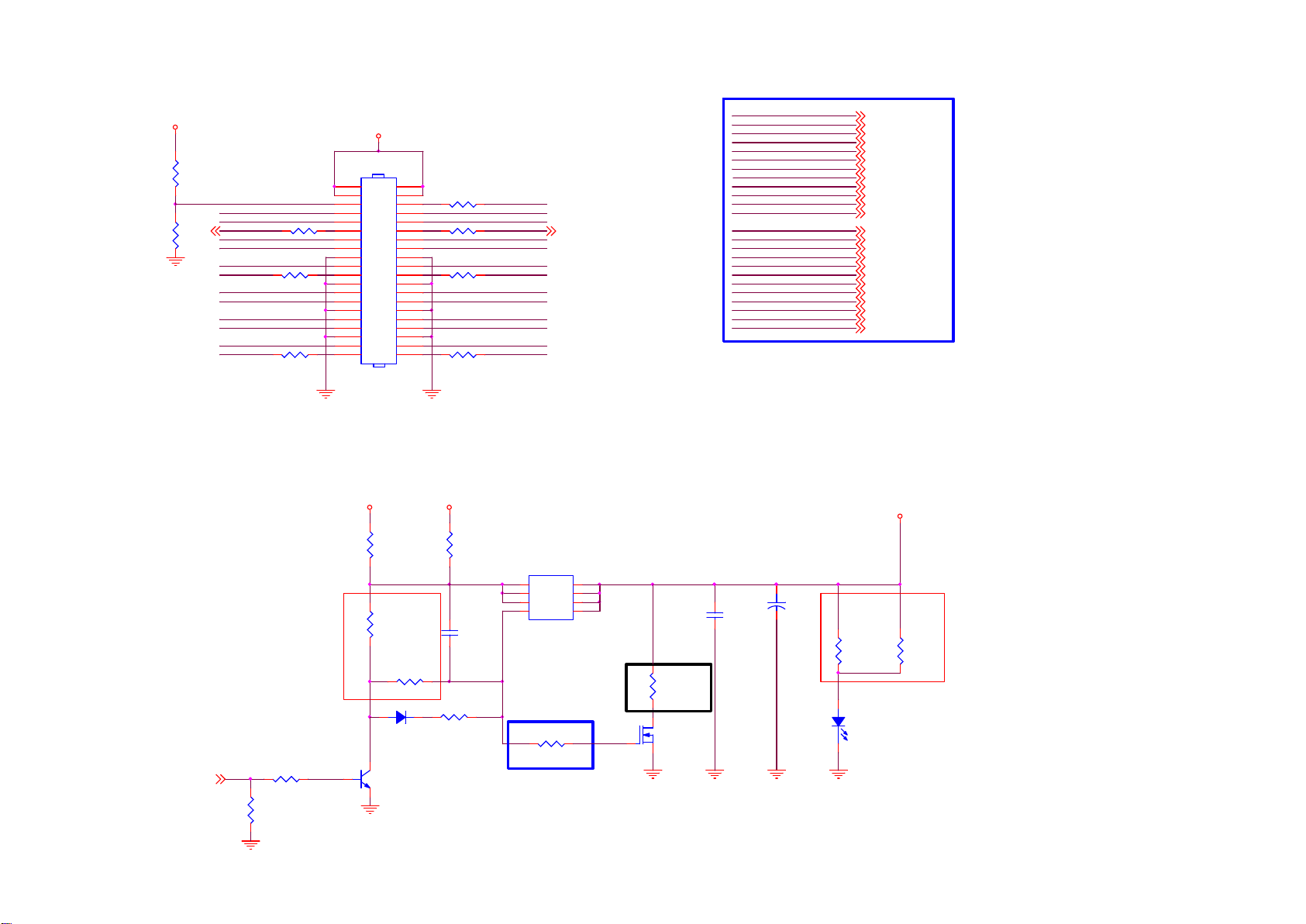
9-3-3 LVDS
+3.3V_Normal
R4113
NC/ 4.7K 1/ 16W
4,9,10
R4115
NC/ 4.7K
M-SCL
LVDS_SEL
RXO0RXO1-
RXO2RXOC-
RXO3RXO4-
RXE0RXE1-
RXE2RXEC-
RXE3RXE4-
SZ LVDS Connector
PANEL_POWER
CN408
40
38
36
34
32
30
28
26
24
22
20
18
16
14
12
10
8
6
4
2
CONN
+12V_Normal
R4122
NC/ 0 OHM +-5% 1/8W
R4124
5K1 1/16W 5%
R4114
NC/ 4.7K
R4117
NC/ 4.7K
R4119
NC/ 4.7K
R4121
NC/ 4.7K
R4116
NC/ 4.7K
R4118
NC/ 4.7K
R4120
NC/ 4.7K
39
37
35
33
31
29
27
25
23
21
19
17
15
13
11
9
7
5
3
1
+5V_Normal
R4123
0 OHM 5% 1/8W
C4101
470NF 16V
PANEL_ON/OFF
RXO0+
RXO1+
RXO2+
RXOC+
RXO3+
RXO4+
RXE0+
RXE1+
RXE2+
RXEC+
RXE3+
RXE4+
Q407
1
S
2
S
3
S
4
G
AO4449 -7A/-30V
M-SDA
12V Panel R733=100K ; R4781=NC
5V Panel R773=NC ; R4781=30K
D
D
D
D
4,9,10
8
7
6
5
C4100
47nF 50V
0603
RXO0RXO0+
RXO1RXO1+
RXO2RXO2+
RXOC-
RXOC+
RXO3RXO3+
RXO4RXO4+
RXE0RXE0+
RXE1RXE1+
RXE2RXE2+
RXECRXEC+
RXE3RXE3+
RXE4RXE4+
+
C4102
NC/ 100UF 25V
RXO0RXO0+
RXO1RXO1+
RXO2RXO2+
RXOCRXOC+
RXO3RXO3+
RXO4RXO4+
RXE0RXE0+
RXE1RXE1+
RXE2RXE2+
RXECRXEC+
RXE3RXE3+
RXE4RXE4+
PANEL_POWER
4
4
4
4
4
4
4
4
4
4
4
4
4
4
4
4
4
4
4
4
4
4
4
4
12V Panel 5V Panel
R4125
100K
R4126
30K 1/10W 5%
PANEL_ON/OFF
High: Panel Power On
Low : Panel Power Off
R4131
4
3K3 1/16W 5%
R4132
10K 1/16W 5%
D4001
BAS316WS
Q402
MMBT3904
R4127
7K5 1/10W 5%
R4129
0R05 OHM
R4130
NC/ 1K 1/16W 1%
R4128
NC/ 470R 1/ 10W 1%
Q411
NC/ 2N7002K
12
LED400
GPTS06033RC3-PB
Page 41
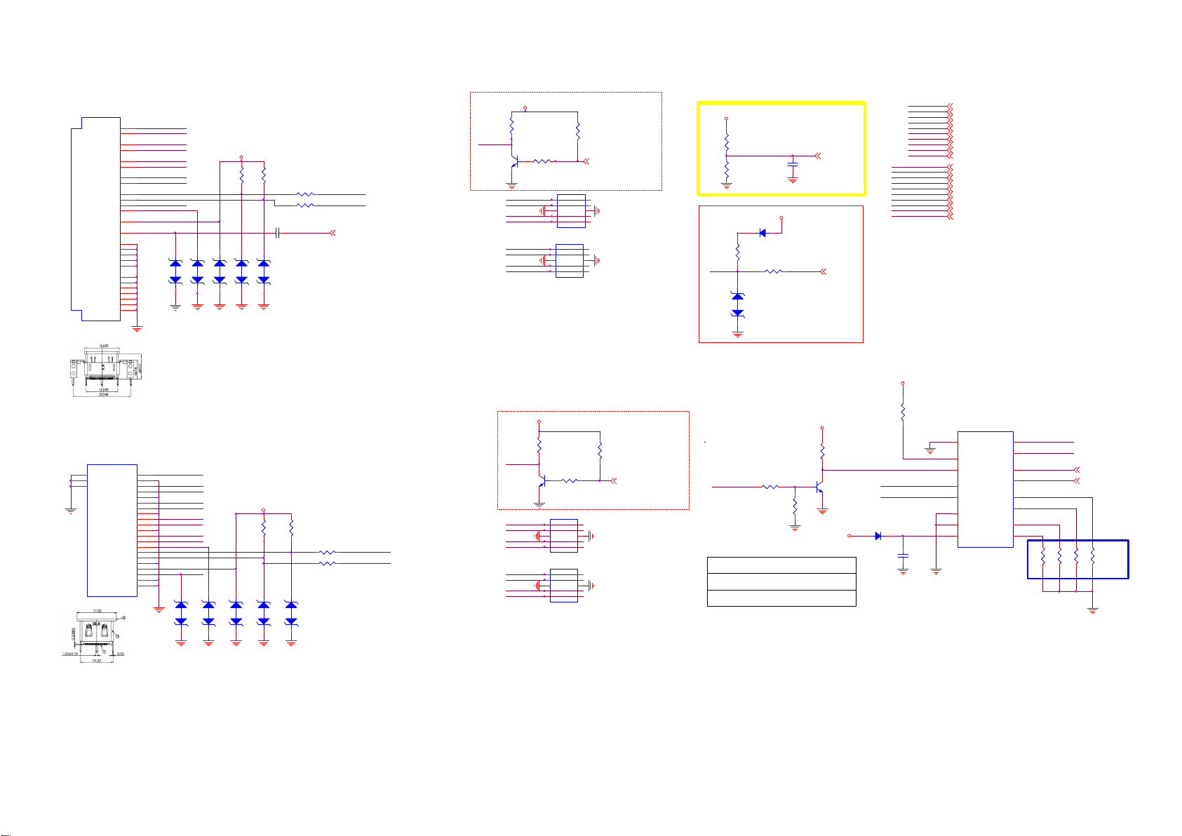
9-3-4 HDMI/ARC/UART
CN501
7
TMDSD0+
9
TMDSD0-
4
TMDSD1+
6
TMDSD1-
1
TMDSD2+
3
TMDSD2-
10
TMDSC+
12
TMDSC-
15
SCL
16
SDA
13
CEC
19
HPD
18
VCC5
14
NC
2
DSHLD0
5
DSHLD1
8
DSHLD2
11
CSHLD0
17
DDC_GN D
20
SHLD_GND1
21
SHLD_GND2
22
SHLD1
23
SHLD2
24
SHLD3
25
SHLD4
26
SHLD5
HDMI V/ T 21P
Side HDM I 2
CEC
SHELL3
SHELL4
SHELL5
V/T 21P 1*1
D2 Shield
D1 Shield
D0 Shield
CK Shield
CE Remot e
DDC CLK
DDC D ATA
GND
HP DET
SHELL1
SHELL2
CN502
D2+
D2-
D1+
D1-
D0+
D0-
CK+
CK-
NC
+5V
22
23
24
HDMI1_RX0P
HDMI1_RX0N
HDMI1_RX1P
HDMI1_RX1N
HDMI1_RX2P
HDMI1_RX2N
HDMI1_CLKP
HDMI1_CLKN
HDMI1-SCL
HDMI1-SDA
CEC
HDMI1-HPD
HDMI-ARC
1
2
3
4
5
6
7
8
9
10
11
12
13
14
15
16
17
18
19
20
21
12
ZD411
HDMI2_RX2P
HDMI2_RX2N
HDMI2_RX1P
HDMI2_RX1N
HDMI2_RX0P
HDMI2_RX0N
HDMI2_CLKP
HDMI2_CLKN
CEC
UART_SEL
HDMI2-SCL
HDMI2-SDA
HDMI2-HPD
12
ZD413
12
ZD408
Rear HDMI 1
ARC
CEC
HDMI1/5V
R4064
R4065
10K
10K
12
ZD407
12
ZD414
ZD410
12
ZD409
HDMI2/5V
R4081
10K
12
ZD415
12
MHL Signal:
CMR:24.57 ~35.54
ohm
DMR:95.3~115 ohm
12
ZD406
R4067
22 OHM 1/16W
R4069
22 OHM 1/16W
C4071
1uF 25V
NC/AZ 5125-01H.R7G
NC/AZ 5125-01H.R7G
NC/AZ 5125-01H.R7G
NC/AZ 5125-01H.R7G
NC/AZ 5125-01H.R7G
R4080
10K
R4082
22 OHM 1/16W
R4083
22 OHM 1/16W
12
ZD416
NC/AZ 5125-01H.R7G
NC/AZ 5125-01H.R7G
NC/AZ 5125-01H.R7G
NC/AZ 5125-01H.R7G
NC/AZ 5125-01H.R7G
HDMI1_SCL
HDMI1_SDA
HDMI_ARC
HDMI2_SCL/R X
HDMI2_SDA/TX
HDMI1/5V
R4059
1K
HDMI1-HPD
Q400
LMBT3904LT1G
R4062
4.7K 1/16W
HDMI1_RX2P
HDMI1_RX2N
HDMI1_RX1P
4
HDMI1_RX1N
ESD <0.5pF
HDMI1_RX0P
HDMI1_RX0N
HDMI1_CLKP
HDMI1_CLKN
HDMI2/5V
HDMI2-HPD
HDMI2_RX2P
HDMI2_RX2N
HDMI2_RX1P
HDMI2_RX1N
ESD <0.5pF
HDMI2_RX0P
HDMI2_RX0N
HDMI2_CLKP
HDMI2_CLKN
LMBT3904LT1G
U500
1
2
3
4
NC/AOZ 8804DI
U502
1
CH1
2
CH2
3
VN
4
CH3
CH45NC
NC/AOZ 8804DI
R4074
1K
Q201
R4078
4.7K 1/16W
U503
1
CH1
2
CH2
3
VN
4
CH3
CH45NC
NC/AOZ8 804DI
U504
1
CH1
2
CH2
3
VN
4
CH3
CH45NC
NC/AOZ8 804DI
CH1
CH2
VN
CH3
CH45NC
NC
NC
VN
NC
NC
NC
VN
NC
R4060
10K
NC
NC
VN
NC
NC
NC
VN
NC
10
9
8
7
6
10
9
8
7
6
HDMI1_HPD IN
10
9
8
7
6
10
9
8
7
6
4
2 in 1(HDMI
OR MHL)
R4076
10K
HDMI2_HPD IN
4
HDMI1/5V
ARC DETECT
R4079=22K(ARC)-->0(NOT ARC)
R4077
10K
R4079
22K1/16W
+3.3V_Standby
D400
BAS316WS
R4208
27K 1/16W 5%
CEC
R4075 100R 1/16W 5%
12
ZD412
NC/AZ 5125-01H.R7G
Factory UART & I2C Switch IC
HDMI Pin-14 for Factory WB & debug
UART_SEL
HDMI
pin14
NC
+12V
R4066
60.4K 1%
40.2K 1/16W 1%
S0
S1
HH
H
L
R4068
C4235
2.2UF 10V
ARC_DEC 4
CEC
HDMI_CEC
+5V_Standby
R4063
10K 1% 1/16W
Q101
LMBT3904LT1G
+5V_Standby
CHANNEL
HDMI function
Debug mode
4
D4000
BAS316WS
HDMI1_RX0P
HDMI1_RX0N
HDMI1_RX1P
HDMI1_RX1N
HDMI1_RX2P
HDMI1_RX2N
HDMI1_CLKP
HDMI1_CLKN
HDMI1_SCL
HDMI1_SDA
HDMI2_RX0N
HDMI2_RX0P
HDMI2_RX1N
HDMI2_RX1P
HDMI2_RX2N
HDMI2_RX2P
HDMI2_CLKN
HDMI2_CLKP
HDMI2_SCL
HDMI2_SDA
+5V_Standby
10K 1% 1/16W
HDMI2_SCL/R X
HDMI2_SDA/TX
C4070
100NF 16V
R4061
S1
S0
HDMI1_RX0P
HDMI1_RX0N
HDMI1_RX1P
HDMI1_RX1N
HDMI1_RX2P
HDMI1_RX2N
HDMI1_CLKP
HDMI1_CLKN
HDMI1_SCL
HDMI1_SDA
HDMI2_RX0N
HDMI2_RX0P
HDMI2_RX1N
HDMI2_RX1P
HDMI2_RX2N
HDMI2_RX2P
HDMI2_CLKN
HDMI2_CLKP
HDMI2_SCL
HDMI2_SDA
6
9
10
3
13
8
7
16
4
4
4
4
4
4
4
4
4
4
4
4
4
4
4
4
4
4
4
4
U501
2Y3
/E
1Y3
S1
2Y2
S0
1Y2
2Z
2Y1
1Z
1Y1
GND
2Y0
VEE
1Y0
VCC
74HC4052PW
01/15 Floating
Pin5, 14, 1, 12
for
HDMI甧Issue
4
HDMI2_SCL
11
HDMI2_SDA
2
UART-RX
15
UART-TX
5
14
1
12
┦
UART-RX
UART-TX
R4070100K
R4071100K
4,8,14
4,8,14
R4072100K
R4073100K
Page 42
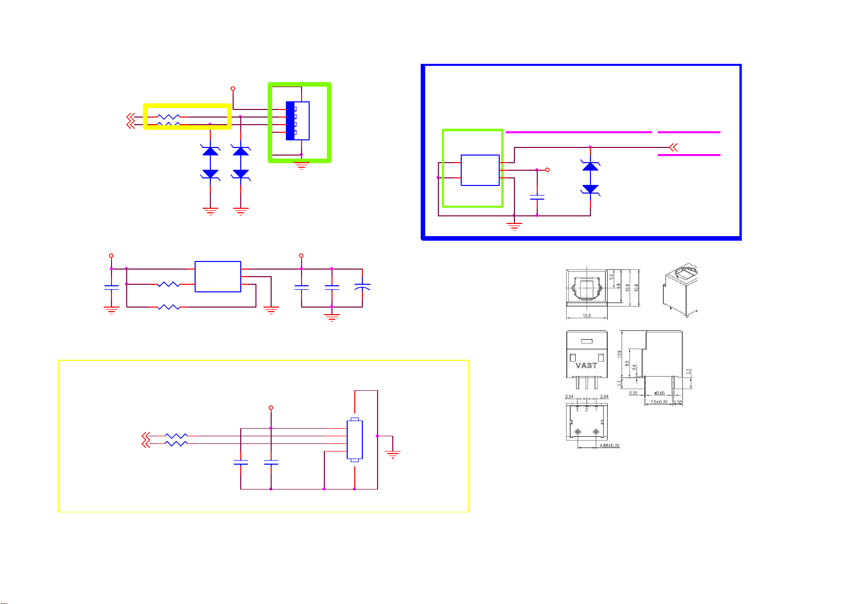
9-3-5 USB/SPDIF
USB 2.0
4
USB0_DM
4
USB0_DP
USB
088G352F6B3AYG
088G352F6B3ACL
+5V_Normal
4.7UF 10% 10V
C4109
R4133 5.1R 1/16W
R4134 5.1R 1/16W
R4138
10K 1/16W 5%
R4137
10K 1/16W 5%
+5V_USB
12
ZD419
U412
5
4
VOUT
VIN
GND
OCB
EN
APL3511CBI-TRG
1
2
3
12
ZD420
1
2
3
4
NC/AZ5125-01H.R7G
NC/AZ5125-01H.R7G
1 2 3 4
6 5
+5V_USB
C4103
10UF 10V
CN103
USB CONN
C4104
100NF 25V
C4105
+
220UF 16V
SPDIF-OPTICAL
CN603
4
TH1
5
TH2
FIBER-OPTIC V/T 3P
8.5mm optica l
VIN
VCC
GND
3
2
1
+5V_Normal
SPDIF _OUT
C4106
100NF 16V
SPDIF
388G359J5B1VAT
388G359J5B1VYG
12
ZD421
NC/AZ5125-01H.R7G
SPDIF_OUT 4
Grounding
+5V_Normal
4
4
USB1_DM
USB1_DP
R4135 NC/5.1R 1/16W
R4136 NC/5.1R 1/16W
NC/ 10UF 10V
C4107
NC/ 100NF 25V
C4108
CN104
56
NC/WAFER 1.25mm
1
2
3
4
Page 43
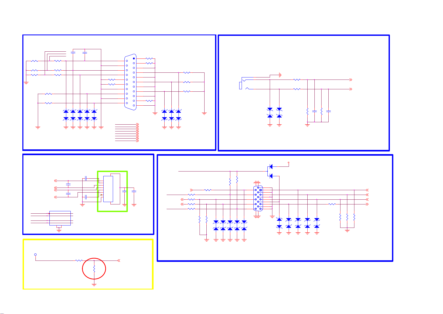
9-3-6 SCART/VGA/RJ45/Audio_in
SCART IN
R4140
10K +-1% 1/16W
R4143
10K +-1% 1/16W
R4146
2K2 1/16W 5%
R4154
75 OHM +-5% 1/16W
R4156
75 OHM +-5% 1/16W
RJ45 IN
4
4
4
4
MDI_RN
MDI_TP
MDI_TN
MDI_RP
MDI_RN
SCART-FS
SCAR-LIN
SCAR-RI N
R4141
10K +-1% 1/16W
R4144
10K +-1% 1/16W
R4147
10K 1/16W 5%
MDI_TP
MDI_TN
MDI_RP
U416
NC/TVU1240R1 A
1
IN1
2
IN2
4
IN3
5
IN4
8
MDI_TP
MDI_TN
MDI_RP
MDI_RN
GND
3
C4158
470pF 50V
12
12
ZD422
ZD423
AZ5125-01H.R7 G
AZ5125-01H.R7 G
AZ5125-01H.R7 G
AZ5125-01H.R7 G
AZ5125-01H.R7 G
C4113
NC/12pF 50V
C4115
NC/12pF 50V
10
NC
9
NC
7
NC
6
NC
GND
C4159
470pF 50V
SCART-RIN
SCART-LIN
SCART_FS
SCART-FB
SCART-AV-IN
12
12
12
ZD424
ZD426
ZD425
C4112
1
10NF 50V
2
3
4
5
6
7
8
C4117
10NF 50V
RJ45 C ONN
TPV: change CN105
RJ45 connector to
meet RFQ request.
12/28
R4148
75 OHM +-5% 1/16W
R4151
75 OHM +-5% 1/16W
SCART-R
SCART-G
SCART-B
SCAR-RI N
SCAR-LIN
SCART-FS
SCART-FB
SCART-AV-IN
9
CN405
TH1
P1
P2
P3
P4
P5
P6
P7 NC
P8
TH2
10
10
12
14
16
18
20
CN151
2
4
6
8
C4114
10UF
SCART 21P
C4116
100nF 50V
1
R4139
75 OHM +-5% 1/16W
3
R4142
75 OHM +-5% 1/16W
5
7
9
11
13
15
17
19
R4155
75 OHM +-5% 1/16W
21
SCART-R 4
SCART-G 4
SCART-B 4
SCAR-RI N 4
SCAR-LIN 4
SCART-FS 4
SCART-FB 4
SCART-AV-IN 4
SCART
388G355HLB1EYG
388G355HLB1EAT
SCART-B
SCART-G
SCART-R
12
ZD427
AZ5125-01H.R7 G
AZ5125-01H.R7 G
AZ5125-01H.R7 G
12
ZD428
R4145
75 OHM +-5% 1/16W
R4150
75 OHM +-5% 1/16W
R4153
75 OHM +-5% 1/16W
12
ZD429
VGA In
VGA_PLUGPWR
UART-RX 4,6,14
UART-TX
UART-RX
R4162 100R 1/16W 5%
R4163 100R 1/16W 5%
VGA-HSYN C4 VGA-B 4
R4164 100R 1/16W 5%
VGA-VSYNC4
R4166 100R 1/16W 5%
R4161 NC/100OHM
R4167
10K 1/16W 5%
10K 1/16W 5%
PC / DVI Audio in
CN102
PHONE J ACK
Check spec.
20140318
R4160
R4168
4K7 1/16W 5%
VGA_SDA
VGA_SCL
12
ZD432
12
ZD433
12
ZD434
12
ZD435
4K7 1/16W 5%R4159
12
ZD436
1
2
3
1716
11
12
13
14
15
18 19
NC/ AZ5123-01H
NC/ AZ5123-01H
NC/ AZ5123-01H
NC/ AZ5123-01H
NC/ AZ5123-01H
12
D4002
BAT54C
CN101
D-SUB 15P
6
1
7
2
8
3
9
4
10
5
ZD430
12
NC/AZ 5123-01H
NC/AZ 5123-01H
ZD431
+5V_Normal
12
ZD441
12
ZD437
R4149
10K 1%
R4152
10K 1%
12
ZD438
R4157
12
ZD439
C4110
R4158
12
ZD440
NC/AZ 5125-01H.R7G
NC/AZ 5123-01H
NC/AZ 5123-01H
NC/AZ 5123-01H
NC/AZ 5123-01H
C4111
10K +-1% 1/16W
470PF
10K +-1% 1/16W
470PF
R4165
NC/10 0OHM
VGA_RIN
VGA_LIN
R4169
R4170
VGA_RIN
VGA_LIN
R4171
75 OHM +-5% 1/16W
75 OHM +-5% 1/16W
75 OHM +-5% 1/16W
4
4
VGA-R 4
VGA-G 4
UART-TX
4,6,14
SCART AUDIO/VIDEO OUT
TP402
NC/0R05 OHM
AV-OUT
R4172
NC/75 OHM 1/16W
R4173
close to IC
CVBS_OUT0
4
Page 44
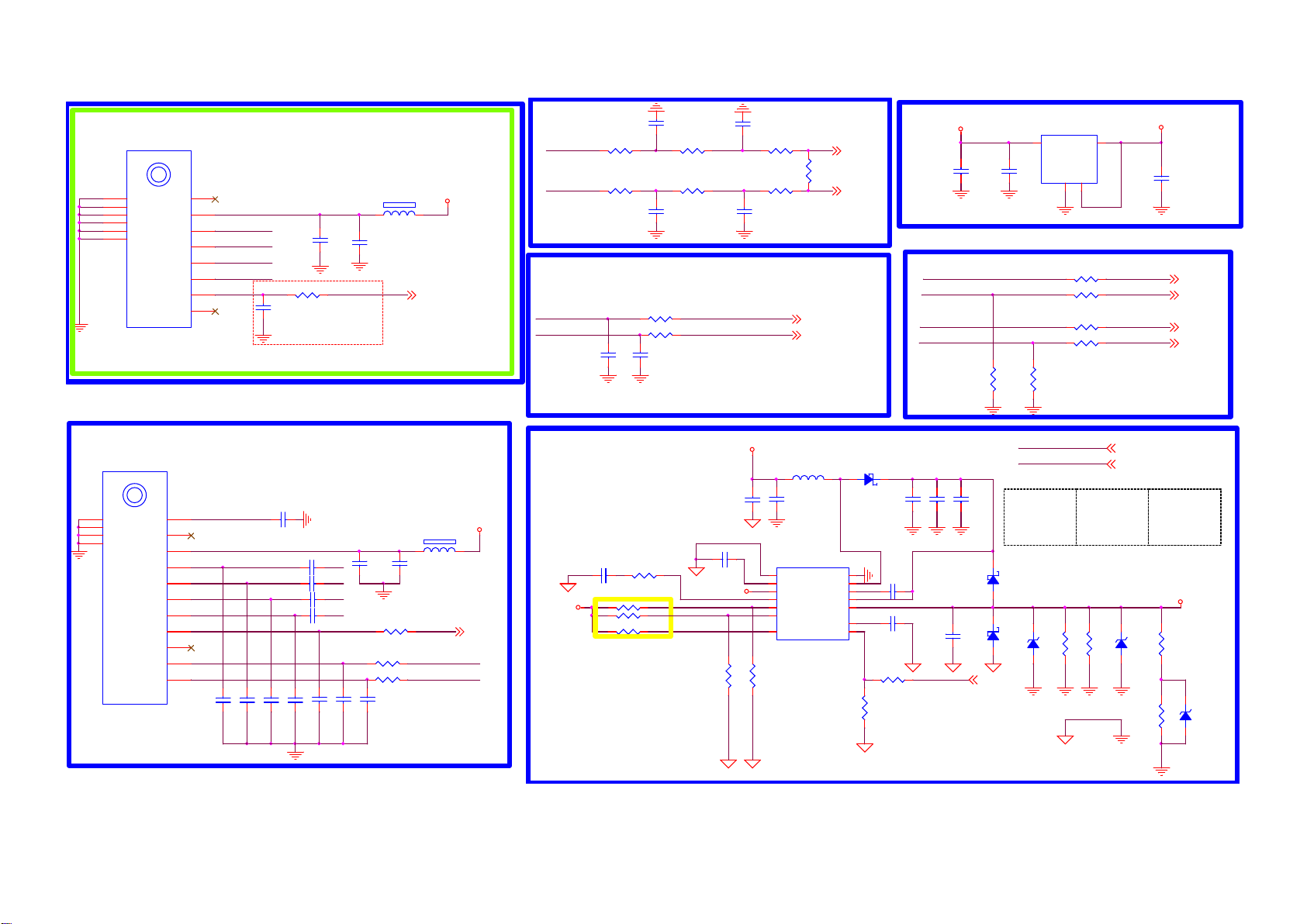
9-3-7 Tuner
1'st Source :LGIT TDSY-G430D (394GPASEBIL02G)
2'nd Source : TCL ST42CS-2-E (394GNPALALL32L)
TU101
T2 TUNER
LGTuner with DVB-C/T/T2
Ant.PWR
SDA
SCL
DIF (N)
DIF (P)
IF AGC
1
2
3
TUN_SDA
4
TUN_SCL
5
TUN_DIF -#T2
6
TUN_DIF +#T2
7
IF_AGC_T
8
NC
100NF 16V
C4127
C4125
100NF 16V
R4183 100OHM
Close Tuner
C4126
10UF 16V
IFAGC _T
1 2
120R 1A
FB411
+3.3V_TU
T2 Tuner IFAGC
IFAGC _T 4
TPV: chang e TU10 3 part s numb er fol low LG . 1/6
9
TH1
10
TH2
11
+B1(+3.3V)
TH3
12
TH4
13
TH5
14
TH6
TPV: change TU102 parts numbe r foll ow LG. 12/30
1'st Source :LG TDQS-A751F (394GPASEBIL05G)
2'nd Source :TCL TUNER EU SS07CA-6-E (394GDVBSALL02L)
TU102
S2 TUNER
C4133
LGTuner with DVB-S/S2
C4148
10PF 50V
C4147
10PF 50V
1NF 50V
C4137
C4141
C4143
C4144
C4150
NC/ 10PF 50V
C4149
1NF 50V
QN
100NF 16V
QP
100NF 16V
IP
100NF 16V
IN
100NF 16V
C4151
22PF 50V
C4138
100NF 16V
120R 3A
10UF 10V
1 2
C4139
S2 Tuner IFAGC
IFAGC _S
R4196
0R05 1/1 6W
CLOSE TO TUNER
R4202
22 OHM 1/16W
R4204
22 OHM 1/16W
C4152
C4153
22PF 50V
FB412
TUNER_SDA
TUNER_SC L
12
TH1
13
TH2
14
TH3
15
TH4
LNB A
TU3.3V
QP Output
IP Outp ut
AGC
X-OUT
SDA
SCL
NC
NC
NC
1
VCC_LNBA
2
3
+3V3_VCC_S2
4
5
6
7
8
IF_AGC_S2_TUN ER
9
10
S2_TUNER_SDA
11
S2_TUNER_SCL
NC/ 10PF 50V
+3.3V_TU
IFAGC _S
DVB-C/T/T2 DIF
TUN_DIF -#T2
TUN_DIF +#T2
CLOSE TO T UNER
R4174
0R05 1/1 6W
R4178
0R05 1/1 6W
C4118
NC/ 10PF 50V
R4175
0R05 1/16W
R4179
0R05 1/1 6W
C4123
NC/ 10PF 50V
Tuner control I2C
TUN_SDA
TUN_SCL
R4186
22 OHM 1/16W
R4187
22 OHM 1/16W
C4128
C4129
NC/ 22PF 50V
NC/ 22PF 50V
LNB POWER SUPPLY
R4190
60.4K 1%
R4191 NC/ 10K
R4192 NC/ 10K
R4193 NC/ 10K
+3.3V_TU
4
C4140
3.3NF 50V
R
R
TUNER_SDA
TUNER_SCL
CLOSE TO TUNER
+12V_Normal
C4130
100NF 25V
C4136 220NF 16V
+12V_Normal
LNB_EN
LNB_LINED ROP
PWM1/13/18V_SW
R4198
10K
C4119
NC/ 10PF 50V
R4176
0R05 1/16W
R4180
0R05 1/16W
C4124
NC/ 10PF 50V
C4131
10UF 16V
U415 MP8124GD Z
8
11
12
10
2
1
R4200
10K
R4177
NC/ 180R
from scaler
M-SDA
M-SCL
L403 10uH
AGND
PGND
BYPASS
VDD
COMP
EN
LINED ROP
13V/18V14EXTM
BST
VBOOST
VOUT
TCAP
DIF - 4
DIF + 4
4,5,10
4,5,10
1 2
SW
D4003
FB340M
4
3
5
C4142 100NF 25V
6
7
9
C4146 22NF 25V
13
R4201
R4203
33 OHM 1/16W
100K 1%
+5V_Normal
Satellite DIF
IP
IN
QP
QN
C4132
C4134
10uF 35V
10uF 35V
C4145
100NF 25V
DISEQC_OU T
C4122
10UF 10V
C4135
10uF 35V
DISEQC
TUNER POWER
U414
AZ1117CH -3.3TRG1
3
VIN
R4189
D4004
FB340M
1 2
D4005
FB340M
1 2
C4121
100NF 16V
LINEDROP:
Low: 13/18V
High:
14/19V
ADJ(GN D)
1
R4181
0R05 1/16W
R4182
0R05 1/16W
R4184
0R05 1/16W
R4185
0R05 1/16W
R4188
NC/0R05 1/16W
NC/0R05 1/16W
LNB_EN
PWM1/13/18V_SW
ESD & Surge
Protect
R4194
ZD442
NC/ PJSD24CW
2.2K 1/4 W
1 2
4
2
VOUT
4
4
13/18V_SW:
High: 18 V
Low: 13V
R4195
2.2K 1/4 W
+3.3V_TU
C4120
22UF 10V
LNB_EN
PWM1/13/18V_SW
LNB_EN:
Low: dis able
Hig h: enable
VCC_LNBA
ZD443
R4197
NC/ PJSD24CW
33K 1%
1 2
R4205
5.1K 1%
IP_S_1
IM_S_1
QP_S_1
QM_S_1
4
4
ZD444
1 2
4
4
4
4
NC/ PJSD24CW
Page 45
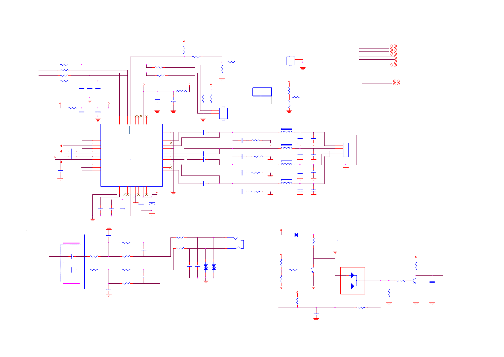
9-3-8 Amplifier/HP
I2SOUTC_DATA
I2SOUTC_MCK
I2SOUTC_BCLK
I2SOUTC_WS
R4357
33 OHM 1/16W
R4368
NC/33 OHM 1/16W
R4367
33 OHM 1/16W
R4360
33 OHM 1/16W
+3.3V_Normal
AMP_3V3
AMP-INL
AMP-INR
R4373 0R 05 1/16W
C4243 1U F 10V
C4248 1U F 10V
1UF 10V
C4236
Close to
NT72461
2.2UF 16V
2.2UF 16V
C4253
C4193
C4195
0402
SDATA
C4262
22PF 50V
22PF 50V
22PF 50V
C4245
100NF 16V
HPR_IN
HPOUTR
HP_SD
UVP
HPOUTL
HPL_IN
10K 1/16W 5%
10K 1/16W 5%
C4260
0402
R4230
R4239
AMP_3V3
C4240
1UF 10V
13
RINN
14
OUTR
15
VSS
16
EN
17
HVSS
18
CN
19
CP
20
HVDD
21
HGND
22
UVP
23
OUTL
24
LINN
C4264
10UF 6. 3V 20%
8
9
10
11
12
SCL
SDA
DVDD
LRCIN
GND25GVDD26VREG27NC28NC29SDATA30GND31GND32NC33PVCC34PVCCR35NC
C4239
C4257
1UF 10V
100NF 16V
C4194
Close to Audio AMP
330pF 50V
C4199
330pF 50V
R4231
10K 1/16W 5%
R4346
27K 1/16W 5%
R4236
27K 1/16W 5%
R4347
10K 1/16W 5%
AMP_3V3
R4371
100K
R4375
NC/1K 1/16W 5%
R4359
33 OHM 1/16W
R4370
33 OHM 1/16W
AMP_POWER AMP_3V3
C4250
4.7UF
1
2NC3NC4NC5SD6
7
FAULT
SDATA
C4241
4.7UF
C4192
C4197
NC
THER_PAD
PVCCL
AMP_POWER
36
HPL_IN
47pF 50V
HPOUTL
HPOUTR
47pF 50V
HPR_IN
BSPL
OUTPL
PGNDL
OUTNL
BSNL
BSNR
OUTNR
PGNDR
OUTPR
BSPR
+
NC
NC
C4259
100uF 25V
BCLK
M-SCL
M-SDA
+12V_AUD
FB416
12
120R 6A
+
C4256
100uF 25V
U601
49
48
47
46
45
44
43
42
41
40
39
38
37
LOUT+
LOUT-
ROUT-
ROUT+
Close to Phone Jack
R4232
0R05 1/10W
R4235
0R05 1/10W
C4198
388G302F3B4FYG
388G302F3B4FCL
C4242 220nF 25V
C4255 220nF 25V
C4244 220nF 25V
C4265 220nF 25V
C4200
R4366
12
ZD445
PIN 7
PIN 6
R4363
4.7K 1/16W
4.7K 1/16W
3
2
1
12
ZD446
R4374
100R 1/16W 5%
R4369
NC/10K 1/16W 5%
CN604
NC/C ONN
C4249
470pF 50V
C4251
470pF 50V
C4237
470pF 50V
C4263
470pF 50V
CN602
1
2
3
PHONE J ACK 3P
100nF 16V
100nF 16V
NC/MLVG0402
NC/MLVG0402
HS600
AMP_PDN
HEAT SINK
AMP_POWER
I2C Address(FAULT)
0X34
Hi
Lo 0X30
11/23 22uH to 10uH, 073G253S 81 M
FB418
1 2
R4354
10 OHM 1%
R4356
10 OHM 1%
R4355
10 OHM 1%
R4362
10 OHM 1%
300R/4A
FB419
1 2
300R/4A
FB420
1 2
300R/4A
FB421
1 2
300R/4A
CLOSE POWER
+5V_Standby
DC OFF
+5V_Normal
R4228
5.1K 1%
R4229
470R 1/16W 5%
R4233
10K 1/16W 5%
H:HP MUTE L:HP ON
AMP_MUTE
1
2
R4364
18K 5% 1/16W
R4358
33K 1/16W 5%
R4372
2K2 1/16W 5%
C4254
NC/1U F 16V
C4266
NC/1U F 16V
C4252
NC/1U F 16V
C4261
NC/1U F 16V
BAS316WS
D4006
+3.3V_Standby
R4237
NC/4. 7K 1/16W
UVP
C4247
3.3nF 50V
C4258
3.3nF 50V
C4238
3.3nF 50V
C4246
3.3nF 50V
AC OFF
R4227
1K 1/16W 1%
A_MUTE
Q405
LMBT3904LT1G
C4201
100N 16V
I2SOUTC_DATA
I2SOUTC_WS
I2SOUTC_BCLK
I2SOUTC_MCK
AMP-INL
AMP-INR
AMP_MUTE
AMP_PDN
I2S
I2SOUTC_DATA 4
I2SOUTC_WS 4
I2SOUTC_BCLK 4
I2SOUTC_MCK 4
AMP-INL
AMP-INR
AMP_MUTE 4
AMP_PDN 4
4
4
MIPS/UART/I2C/ICE
M-SDA
M-SCL
CN601
CONN
4
L+
L-
R-
R+
3
2
1
C4191
22uF 10V
L+
LR+
R-
5 6
POP NOISE
1
D4007
3
2
HP_MUTE
NC/BAV70
R4351
0R05 1/16W
M-SDA 4,5,9
M-SCL
R4238
2.2K 1/16W
R4240
47K 1/16W
AMP_3V3
R4234
10K
Q408
MMBT3904
4,5,9
HP_SD
C4196
10UF 6. 3V 20%
Page 46
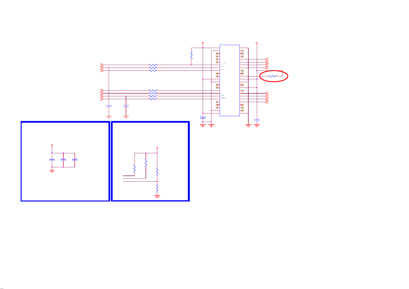
9-3-9 NAND Flash
NAND _RBZ
NAND _REZ
NAND _CEZ
NAND _CLE
NAND_ALE
NAND _WEZ
NAND _WP
C4203
NC/ 33P 50V
4
4
4
4
4
4
4
C4202
NC/ 33P 50V
R4252 0R05 OHM
R4251 0R05 OHM
R4250 0R05 OHM
R4245 0R05 OHM
R4244 0R05 OHM
R4243 0R05 OHM
R4242 0R05 OHM
Close to SOC
Close to SOC
NAND-RBZ-1
NAND-REZ-1
NAND-CEZ-1
NAND-CLE-1
NAND-ALE-1
NAND-WEZ-1
NAND-WP-1
NAND FLASH
+3.3V_Standby +3.3V_Standby
R4241
10K
C4204
100NF 25V
U402
1
NC
2
NC
3
NC
4
NC
5
NC
6
NC
7
RB
8
R
9
E
10
NC
11
NC
12
VDD
13
VSS
14
NC
15
NC
16
CL
17
AL
18
W
19
WP
20
NC
21
NC
22
NC
23
NC
NC24NC
W29N01HVSINF
I/O7
I/O6
I/O5
I/O4
VDD
VSS
I/O3
I/O2
I/O1
I/O0
48
NC
47
NC
46
NC
45
NC
44
43
42
41
40
NC
39
NC
38
NC
37
36
35
NC
34
NC
33
NC
32
31
30
29
28
NC
27
NC
26
NC
25
C4205
100NF 25V
PCM-A7
PCM-A6
PCM-A5
PCM-A4
R4246
NC/ 0R05 OHM
Micron Nand need to NC
PCM-A3
PCM-A2
PCM-A1
PCM-A0
12
12
12
12
12
12
12
12
NAND Power
+3.3V_Standby
C4206
2.2UF 10V
C4207
100NF 25V
100NF 25V
C4208
SPI NAND-MICRON
+3.3V_Standby
R4247
NC/ 4.7K1/16W
R4248
NC/ 4.7K1/16W
NAND -WEZ-1
NAND -CEZ-1
NAND -WP-1
R4249
NC/ 4.7K1/16W
R4253
4.7K 1/16W
3.3V
Winbond 356G3333001607, NAND FLASH W29N01HVSINF 1Gb TSOP-48 ECC 4 bit
MXIC 356G3333001604 FLASH MX30LF1G18AC
Page 47
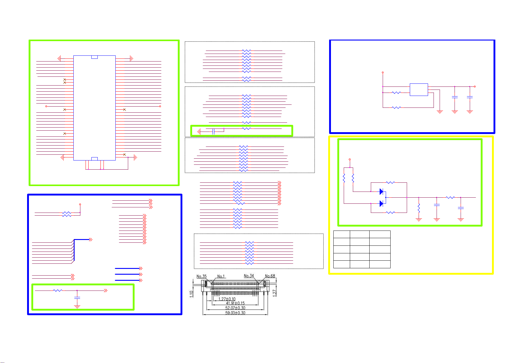
9-3-10 PCMCI
PCM_CD1_N
TS0-D3
TS0-D4
TS0-D5
TS0-D6
PCM-IORD-N
PCM-IOWR-N
TS1-SYNC
TS1-D0
TS1-D1
TS1-D2
TS1-D3
+5V_PCMCIA
TS1-D4
TS1-D5
TS1-D6
TS1-D7
TS0-CLK
PCM-RESET
PCM-WAIT-N
PCM-REG-N
TS0-VLD
TS0-SYNC
TS0-D0
TS0-D1
TS0-D2
PCM_CD2_N
PCM_IRQA_N
PCM_WAIT_N
TS0_D0
TS0_D1
TS0_D2
TS0_D3
TS0_D4
TS0_D5
TS0_D6
TS0_D7
TS0-CLK
CI Bus Power Control
35
GND
36
CD1#
37
D11
38
D12
39
D13
40
D14
TS0-D7
41
D15
42
CE2#
43
VS1#
44
IORD#
45
IOWR#
46
A17
47
A18
48
A19
49
A20
50
A21
51
VCC
52
VPP2
53
A22
54
A23
55
A24
56
A25
57
VS2#
58
RESET
59
WAIT#
60
INPACK
61
REG#
62
BVD2#:SPKR
63
BVD1#:STSCHG
64
D8
65
D9
66
D10
67
CD2#
68
GND
PCMCIA
72
PCMCIA C ARD
READY #:IREQ#
717172
70
CN159
696970
GND
CE1#
A10
OE#
A11
A13
A14
WE#
VCC
VPP1
A16
A15
A12
WP#
GND
D3
D4
D5
D6
D7
A9
A8
A7
A6
A5
A4
A3
A2
A1
A0
D0
D1
D2
TPV: change CN106 parts number follo w LG. 1 /4
+5V_PCMCIA
R4300
4.7K 1/16W
R4303
4.7K 1/16W
TS0_D[7:0]
TS0_D[7:0]
TS0_SYNC
TS0_VLD
R4318
22 OHM 1/16W
TS0_SYNC 4
TS0_VLD 4
TS0_CLK
C4214
10PF 50V
Msta r: Near SoC
TS0_CLK
1
2
3
4
5
6
7
8
9
10
11
12
13
14
15
16
17
18
19
20
21
22
23
24
25
26
27
28
29
30
31
32
33
34
PCM_CD_N
PCM_RESET
PCM_WAIT_N
PCM_REG_N
PCM_OE_N
PCM_WE_N
PCM_IORD_N
PCM_IOWR_N
PCM_CE_N
4
PCM_IRQA_N
PCM_A[14:0]
PCM_D[7:0]
TS1_VLD
TS1_CLK
PCM-D3
PCM-D4
PCM-D5
PCM-D6
PCM-D7
PCM-CE-N
PCM-A10
PCM-OE-N
PCM-A11
PCM-A9
PCM-A8
PCM-A13
PCM-A14
PCM-WE-N
PCM-IRQA-N
TS1-VLD
TS1-CLK
PCM-A12
PCM_A7
PCM_A6
PCM_A5
PCM_A4
PCM_A3
PCM_A2
PCM_A1
PCM_A0
PCM-D0
PCM-D1
PCM-D2
PCMCIA
TS1_VLD
PCM_CD_N
PCM_RESET
PCM_WAIT_N
PCM_REG_N
PCM_OE_N
PCM_WE_N
PCM_IORD_N
PCM_IOWR_N
PCM_CE_N
PCM_IRQA_N
PCM_A[14:0]
PCM_D[7:0]
TS1_D[7:0]
TS1_CLK
TS1_SYNC
TS1_SYNC
4
+5V_PCMCIA
4
4
4
4
4
4
4
4
4
4
4
4
4
TS0-D0~D7
TS0-D0
R4254 22 OH M 1/16W
TS0-D1
R4255 22 OH M 1/16W
R4256 22 OH M 1/16W
TS0-D3
R4257 22 OH M 1/16W
TS0-D4
R4258 22 OH M 1/16W
TS0-D5
R4259 22 OH M 1/16W
R4260 22 OH M 1/16W
TS0-D7
R4261 22 OH M 1/16W
TS0-VLD TS0_VLD
R4262 22 OH M 1/16W
TS0-SYNC
R4263 22 OH M 1/16W
TS1-D0~D7
TS1-D0
R4265 22 OH M 1/16W
TS1-D1 TS1_D1
R4266 22 OH M 1/16W
TS1-D5
TS1-D7
TS1-SYNC
TS1-CLK
R4267 22 OH M 1/16W
R4268 22 OH M 1/16W
R4269 22 OH M 1/16W
R4272 22 OH M 1/16W
R4273 22 OH M 1/16W
R4274 22 OH M 1/16W
R4275 22 OH M 1/16W
R4276 22 OH M 1/16W
R4277 22 OH M 1/16W
TS1-D3
TS1-D4
TS1-D6
C4211 10PF 50V
TS0_D0
TS0_D1
TS0_D2TS0-D2
TS0_D3
TS0_D4
TS0_D5
TS0_D6TS0-D6
TS0_D7
TS0_SYNC
TS1_D0
TS1_D2TS1-D2
TS1_D3
TS1_D4
TS1_D5
TS1_D6
TS1_D7
TS1_SYNC
TS1_VLDTS1-VLD
Msta r: Near CI
TS1_CLK
NEAR
SOC
PCMCIA POWER
+5V_Normal
R4270
4.7K 1/16W
R4271
4.7K 1/16W
CLOSE TO CI CONNECTOR
U413
5
VIN
4
EN
APL3511CBI-TRG
VOUT
GND
OCB
CI_OCP
1
2
3
C4209
100NF 16V
+5V_PCMCIA
C4210
10UF 16V
PCM Signal
PCM-RESET
PCM-IRQA-N
PCM-WE-N PCM_WE_N
PCM-IOWR- N
PCM-OE-N
PCM-IORD-N
PCM-CE-N
PCM-REG-N
PCM-WAIT-N
PCM_A0
PCM_A1
PCM_A2
PCM_A3
PCM_A4
PCM_A5
4
4
4
PCM_A6
PCM_A7
PCM_A8
PCM_A9
PCM_A10 PCM-A10
PCM_A11 PCM-A11
PCM_A12 PCM-A12
PCM_A13 PCM-A13
PCM_A14
R4278 22 OH M 1/16W
R4279 22 OH M 1/16W
R4280 22 OH M 1/16W
R4281 22 OH M 1/16W
R4282 22 OH M 1/16W
R4283 22 OH M 1/16W
R4284 22 OH M 1/16W
R4285 22 OH M 1/16W
R4286 22 OH M 1/16W
PCM-D0 ~D7
PCM-D7
R4310 22 OH M 1/16W
PCM-D6 PCM_D6
R4311 22 OH M 1/16W
PCM-D5
R4312 22 OH M 1/16W
PCM-D4
R4313 22 OH M 1/16W
PCM-D3
R4314 22 OH M 1/16W
PCM-D2
R4315 22 OH M 1/16W
PCM-D1
R4316 22 OH M 1/16W
PCM-D0 PCM_D0
R4317 22 OH M 1/16W
R429922 OHM 1/16W
R430222 OHM 1/16W
R430422 OHM 1/16W
R430522 OHM 1/16W
R430722 OHM 1/16W
R430822 OHM 1/16W
R430922 OHM 1/16W
R428722 OHM 1/16W
R429122 OHM 1/16W
R429222 OHM 1/16W
R429322 OHM 1/16W
R429422 OHM 1/16W
R429522 OHM 1/16W
R429622 OHM 1/16W
R429822 OHM 1/16W
PCM_RESET
PCM_IRQA_N
PCM_IOWR_N
PCM_OE_N
PCM_IORD_N
PCM_CE_N
PCM_REG_N
PCM_WAIT_N
PCM-A0
PCM-A1
PCM-A2
PCM-A3
PCM-A4
PCM-A5
PCM-A6
PCM-A7
PCM-A8
PCM-A9
PCM-A14
PCM_D7
PCM_D5
PCM_D4
PCM_D3
PCM_D2
PCM_D1
PCM-A0 ~A14
PCM-A0
PCM-A1
PCM-A2
PCM-A3
PCM-A4
PCM-A5
PCM-A6
PCM-A7
+5V_Normal
TPV: follow offic ial CKT. 1/4
R4289
R4288
2K2 1/16W 5%
11
11
11
11
11
11
11
11
2K2 1/16W 5%
PCM_CD1_N
PCM_CD2_N
PCM_CD2_N
GND 0 V
GND
NC
GND
NC
GND
NC
NC H
2
1
PCM_CD_NPCM_CD1_N
L
H
H
R4290
NC/ 0R05 1/16W
D4008
BAT54CH
R4306
NC/ 0R05 1/16W
2.5V
2.5V
5V
3
R4301
4.7K 1/ 16W
CARD DETECT
R4297
1K 1/16W 5%
C4212
1N 50V
PCM_CD_N
C4213
100pF 50V
Page 48
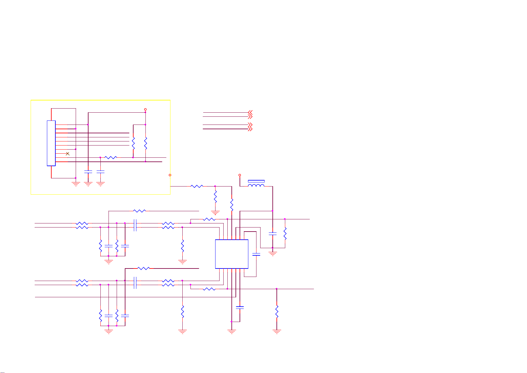
9-3-11 BT
B/T FUNCTION
for EMI solution
BT_LED trace (connector 狠)
糤
NC , C640 , C641, C642 , C643
470pF bypass cap.
+3.3V_Standby
CN605
1112
CONN
1
2
BT_AUD_R_N
BT_AUD_R_P
BT_AUD_L_P
BT_AUD_L_N
BT_EN
3
4
5
6
7
8
9
10
R4326 10K +-1% 1/16W
R4328 10K +-1% 1/16W
R4335 10K +-1% 1/16W
R4337 10K +-1% 1/16W
R4264
100R 1/ 16W 1%
C4215
C4216
100NF 16V
R4331
R4340
BT_AUD_L_P
BT_AUD_L_N
BT_AUD_R_P
BT_AUD_R_N
470pF 50V
R4332
C4220
R4343
C4226
R4320
R4319
10K
10K
R4324
NC/0R05 1/16W
C4217 1U F 6.3V
C4218 1U F 6.3V
C4221
10K +-1% 1/16W
470pF
10K +-1% 1/16W
470pF
R4334
NC/ 0R05 1/16W
C4223 1U F 6.3V
C4224 1U F 6.3V
C4227
10K +-1% 1/16W
470pF
10K +-1% 1/16W
470pF
BT_LED
BT_EN
+5V_Normal +3.3V_Normal
BT_AUD_R
R4327 10K
R4329 10K
R4333
39K 1/16W 5%
BT_AUD_L
R4336 10K
R4338 10K
R4341
39K 1/16W 5%
R4321
1K5
BT-EN
BT_LED
BT_AUD_R
BT_AUD_L
R4325
39K 1/16W 5%
R4339
39K 1/16W 5%
R4322
1K
11
12
13
14
RIN P
RIN N
OUTR
LINP1LINN2OUTL3SGND4EN5PVSS6CN
FB417
1 2
120R
R4323
30K
8
9
10
CP
UVP
PVDD
PGND
U602
7
AD22650-QH14NAT
C4225
1UF 6.3V
BT_EN
BT_LED 4
BT_AUD_R 4
BT_AUD_L 4
C4219
C4222
1UF 6.3V
R4342
NC
4
BT_AUD_R
R4330
NC/ NC
1UF 6.3V
BT_AUD_L
Page 49
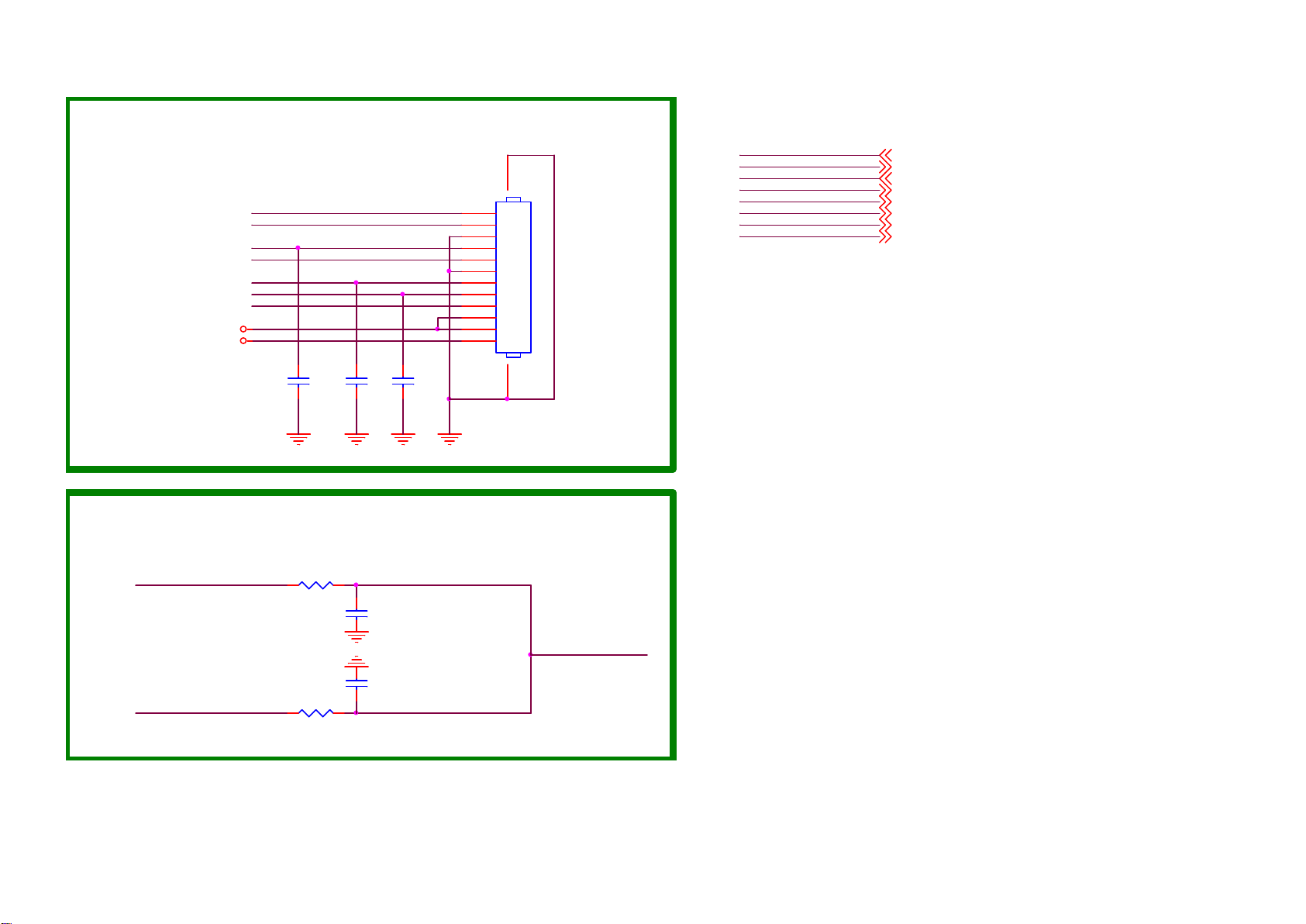
9-3-12 HOTEL function
For BUH daughter board
UART-RX
UART-TX
BATH_L_R
BATH_AMP_EN
IR_RC
IRIN
STANDBY
+5V_Normal
+3.3V_Standby
CN606
NC/CONN
1
2
3
4
5
6
7
8
9
10
11
12
UART-RX
UART-TX
1314
BATH_AMP_EN
STANDBY
IR_RC
IRIN
AUOUT_L0
AUOUT_R0
UART-RX
UART-TX
BATH_AMP_EN
STANDBY
IR_RC 4
IRIN 4
AUOUT_L0
AUOUT_R0
4,6,8
4,6,8
4
3
4
4
C4228
NC/ 1N 50V
C4229
NC/1N 50V
C4230
NC/1N 50V
Bathroom SPK audio out for BUH
AUOUT_L0
AUOUT_R0
R4344 NC/0R
C4231
NC/ 1N 50V
C4232
NC/ 1N 50V
R4345 NC/0R
BATH_L_R
Page 50
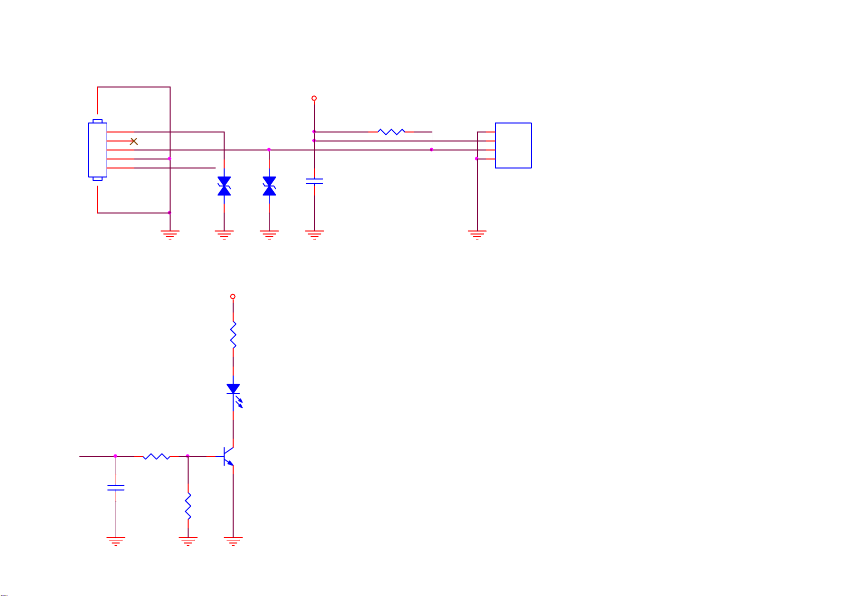
9.4 J 715G8576 IR/LED Panel (For 24” 5603 Series)
9-4-1 IR LED
CONN
CN1
67
1
2
3
4
5
033G8032 5F S HR
LED_R
IR
VCC
ZD2
1 2
VCC
12
ZD1
1 2
NC/MLVG0402
R2
2K7 1/16W 5%
NC/MLVG0402
VCC
C1
2.2uF 10V
R1
15K 1/16W 5%
U1
1
GND
2
VCC
3
Vout
4
GND
TSOP75436TR
LED_R
LED1
GPSS008RC4
R5
22K 1/16W 5% Q1
C2
100N 16V
R7
22K 1/16W 5%
BC847BW
Page 51
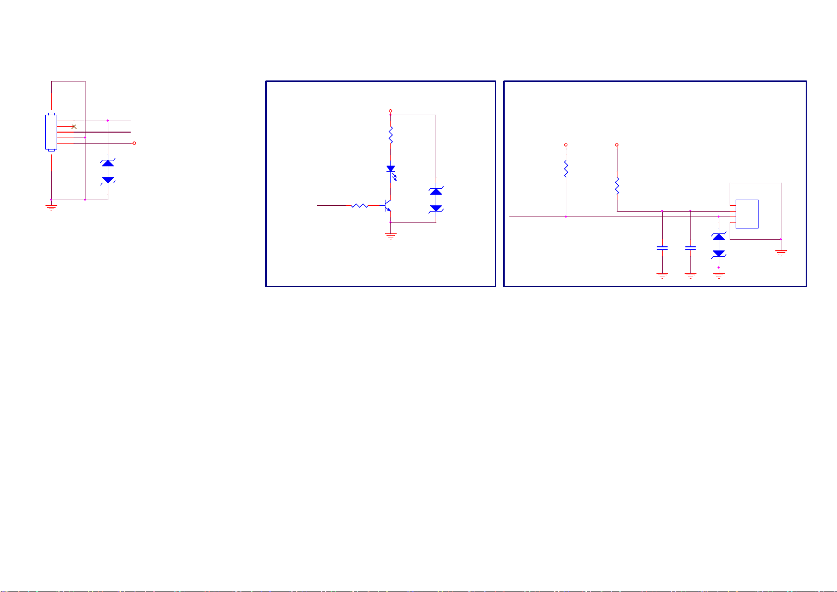
9.5 J 715G8767 IR/LED Panel (For 32” 5603 Series)
9-5-1 IR & LED & Light Sensor
CN201
CONN
67
1
2
3
4
5
LED_R
RC-I R
12
3V3SB
ZD202
NC/ AZ5125-01H.R7G
Standby LED
LED201
GPSS008RC4
LED_R
R202
22K 1/16W 5%
3V3SB
12
R201
2K7 1/16W 5%
Red
Q201
BC847BW
12
ZD203
AZ5125-01H.R 7G
IR Receiver
3V3SB
R203
NC/ 2K7 1/16W 5%
RC-IR
3V3SB
R204
100R 1/16W 5%
Close to U201
C202
1uF 10V
C201
1uF 10V
U201
TSOP75436TR
1
GND
2
VCC
3
Vout
4
12
GND
ZD201
NC/ AZ5125-01H.R7G
Page 52
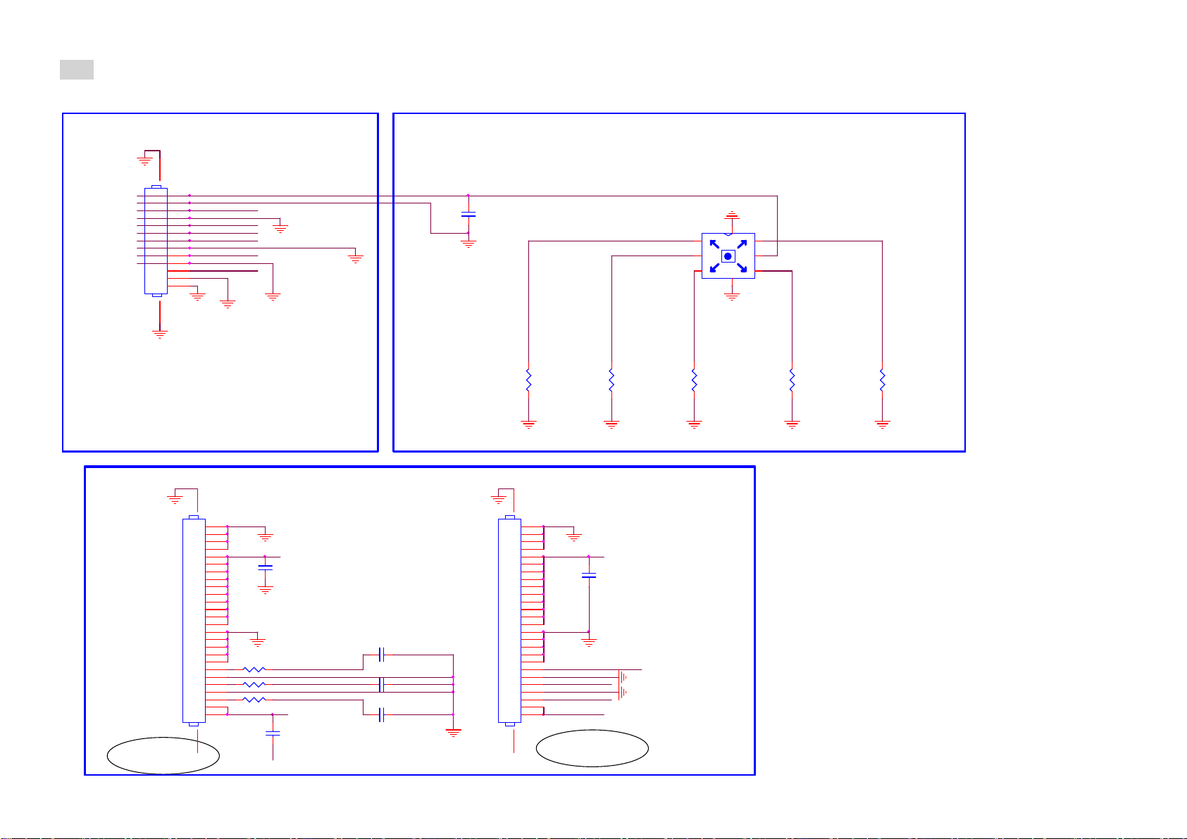
9.6 E 715G7088 Keyboard control panel (For 32” 5603 Series)
9-6-1 Key
CONN TO SSB
CN01
1415
1
2
3
4
5
6
7
8
9
10
11
12
13
GND_AL
CONN 13P 1.25MM
Co-layot
TO AMBI LIGHT
CONN 26P
CN03
311GF050N26BDX
/311GF050N26BDJ
KEY1
AMBI_SPI_CLK
AMBI_SPI_MOSI
+12V_AMBI
+12V_AMBI
AMBI_TEMP
+12V_AMBI
GND_AL
2728
1
2
3
4
5
+12V_AMBI
6
7
8
9
10
11
12
13
14
15
16
17
18
19
20
R10 0R 05 1/16W
21
22
R9 0R05 1/ 16W
23
24
R8 NC/ 0R05 1/16W
25
26
+3V3_AMBI
GND_AL
GND_AL
GND_AL
C07
1uF 16V X5R
GND_AL
GND_AL
C08
1UF 10V
----><----|
AMBI_SPI_MOSI
GND_AL
AMBI_TEMP
AMBI_SPI_CLK
JOYSTICK
C09
NC/ 100PF 50V
C10 N C/100PF 50V
C11 N C/100PF 50V
C06
100PF 50V
CONN 26P
CN02
Right
----><----|
R01
1K2 1/10W 1%
26
25
24
23
22
21
20
19
18
17
16
15
14
13
12
11
10
9
8
7
6
5
AMBI_SPI_CLK
4
3
AMBI_SPI_MOSI
2
1
27 28
311GF050N26BDX
/311GF050N26BDJ
+12V_AMBI
GND_AL
AMBI_TEMP
+3V3_AMBI
GND_AL
Center
------------
----><----|
R02
47R 1/1 0W 1%
C12
1uF 16V X5R
7
1 6
F5
2
F1
3 4
F3
8
SW01
Down
------
----><----|
R03
6K8 1/10W 1%
F4
5
F2
TACT SW 6P
R04
Left
------
2K2 1/10W 1%
Up
R05
------
15K 1/10W 1%
----><----|
----><----|
Page 53
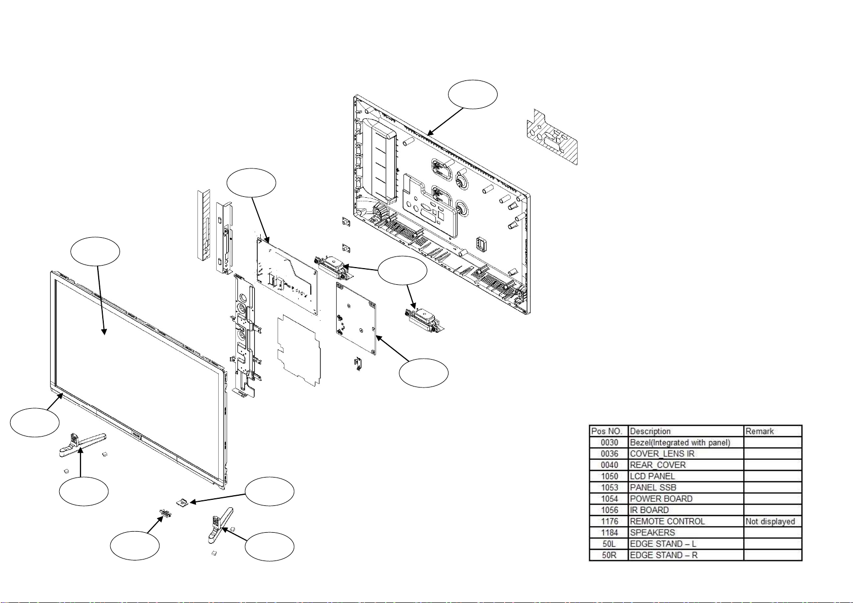
10. Styling Sheets
10.1 5603 series 24”
1050
0040
1053
1184
0030
50L
0036
1054
1056
50R
Page 54
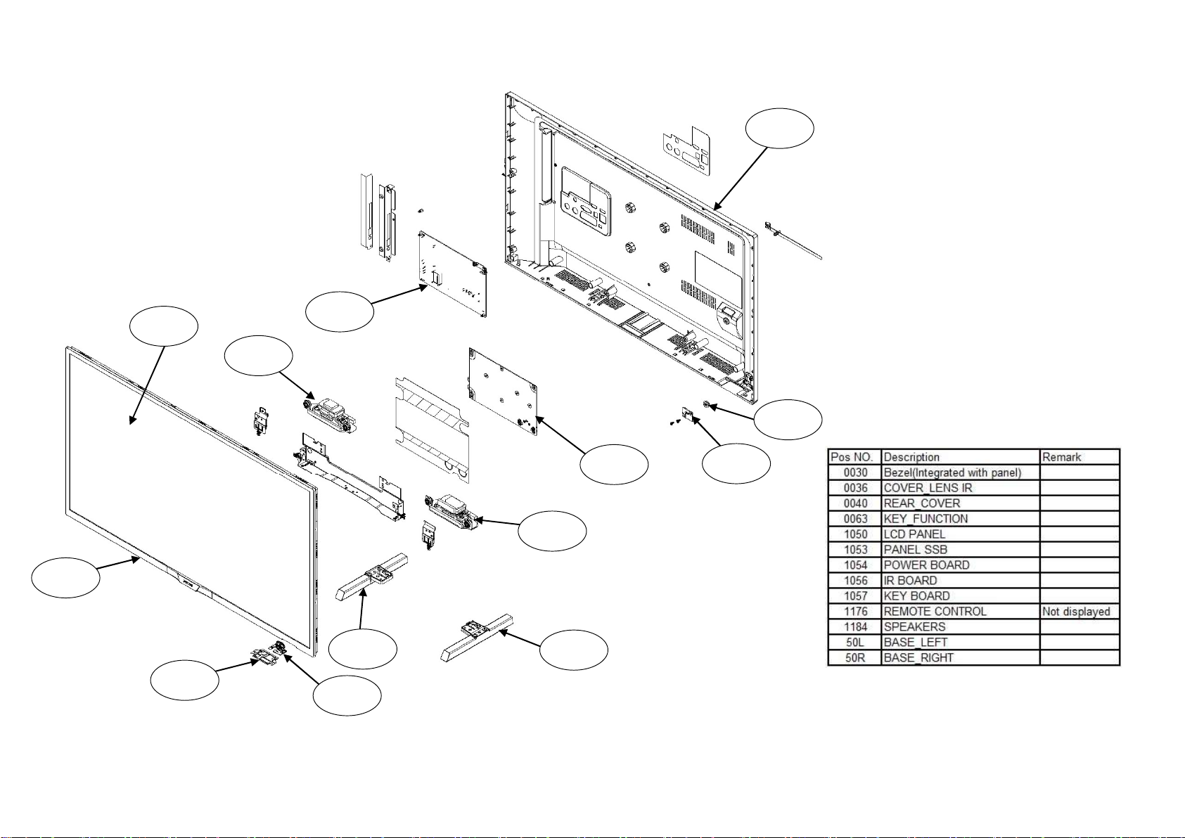
10.2 5603 series 32”
1050
0040
1053
1184
0063
0030
0036
50L
1056
1184
50R
1054
1057
 Loading...