

Philips 27H8, 32H8, 33H8, 36H8 Service Manual


IMPORTANT SAFETY NOTICE
Proper service and repair is important to the safe, reliable operation of all Philips
Consumer Electronics Company** Equipment. The service procedures recommended by
Philips and described in this service manual are effective methods of performing service
operations. Some of these service operations require the use of tools specially designed
for the purpose. The special tools should be used when and as recommended.
It is important to note that this manual contains various CAUTIONS and NOTICES
which should be carefully read in order to minimize the risk of personal injury to service
personnel. The possibility exists that improper service methods may damage the
equipment. It also is important to understand that these CAUTIONS and NOTICES
ARE NOT EXHAUSTIVE. Philips could not possibly know, evaluate and advise the
service trade of all conceivable ways in which service might be done, or of the possible
hazardous consequences of each way. Consequently, Philips has not undertaken any such
broad evaluation. Accordingly, a servicer who uses a service procedure or tool which is
not recommended by Philips must first satisfy himself thoroughly that neither his safety
nor the safe operation of the equipment will be jeopardized by the service method
selected.
** Hereafter throughout this manual, Philips Consumer Electronics Company will be
referred to as Philips.
WARNING
Critical components having special safety characteristics are identified with a or
"S" by the Ref. No. in the parts list and enclosed within a broken line* (where
several critical components are grouped in one area) along with the safety symbol
on the schematics or exploded views. Use of substitute replacement parts which
do not have the same specified safety characteristics may create shock, fire, or other
hazards. Under no circumstances should the original design be modified or altered
without written permission from Philips. Philips assumes no liability, express or
implied, arising out of any unauthorized modification of design. Servicer assumes all
liability.
* Broken Line ____ _ ____ _ ____ _ ____

FIRE AND SHOCK HAZARD
1. Be sure all components are positioned in such a way as to avoid the possibility of adjacent component
shorts. This is especially important on those chassis which are transported to and from the service shop.
2. Never release a repaired unit unless all protective devices such as insulators, barriers, covers, strain
reliefs, and other hardware have been installed in accordance with the original design.
3. Soldering and wiring must be inspected to locate possible cold solder joints, solder splashes, sharp solder
points, frayed leads, pinched leads, or damaged insulation (including the ac cord). Be certain to remove
loose solder balls and all other loose foreign particles.
4. Check across-the-line components and other components for physical evidence of damage or
deterioration and replace if necessary. Follow original layout, lead length, and dress.
5. No lead or component should touch a receiving tube or a resistor rated at 1 watt or more. Lead tension
around protruding metal surfaces or edges must be avoided.
6. Critical components having special safety characteristics are identified with an 'S' by the Ref. No. in the
parts list and enclosed within a broken line* (where several critical components are grouped in one area)
along with the safety symbol on the schematic diagrams and /or exploded views.
7. When servicing any unit, always use a separate isolation transformer for the chassis. Failure to use a
separate isolation transformer may expose you to possible shock hazard, and may cause damage to
servicing instruments.
8. Many electronic products use a polarized ac line cord (one wide pin on the plug). Defeating this safety
feature may create a potential hazard to the servicer and the user. Extension cords which do not
incorporate the polarizing feature should never be used.
9. After reassembly of the unit, always perform an ac leakage test or resistance test from the line cord to all
exposed metal parts of the cabinet. Also, check all metal control shafts (with knobs removed), antenna
terminals, handles, screws, etc., to be sure the unit may be safely operated without danger of electrical
shock.
* Broken line ____ _ ____ _ ____ _ ____

LEAKAGE CURRENT COLD CHECK
1. Unplug the ac line cord and connect a jumper between the two prongs of the plug.
2. Turn on the power switch.
3. Measure the resistance value between the jumpered ac plug and all exposed cabinet parts of the receiver,
such as screw heads, antennas, and control shafts. When the exposed metallic part has a return path to the
chassis, the reading should be between 1 megohm and 5.2 megohms. When the exposed metal does not
have a return path to the chassis, the reading must be infinity. Remove the jumper from the ac line cord.
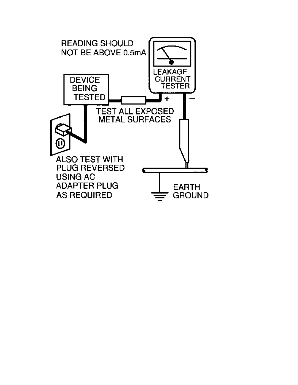
LEAKAGE CURRENT HOT CHECK
1. Do not use an isolation transformer for this test. Plug the completely reassembled receiver directly into
the ac outlet.
2. Connect a 1.5k, 10W resistor paralleled by a 0.15uF. capacitor between each exposed metallic cabinet
part and a good earth ground such as a water pipe, as shown below.
3. Use an ac voltmeter with at least 5000 ohms/volt sensitivity to measure the potential across the resistor.
4. The potential at any point should not exceed 0.75 volts. A leakage current tester may be used to make
this test; leakage current must not exceed 0.5mA. If a measurement is outside of the specified limits,
there is a possibility of shock hazard. The receiver should be repaired and rechecked before returning it
to the customer.
5. Repeat the above procedure with the ac plug reversed. (Note: An ac adapter is necessary when a
polarized plug is used. Do not defeat the polarizing feature of the plug.)
OR
With the instrument completely reassembled, plug the ac line cord directly into a 120Vac outlet. (Do not
use an isolation transformer during this test.) Use a leakage current tester or a metering system that
complies with American National Standards Institute (ANSI) C101.1 Leakage Current for Appliances and
Underwriters Laboratories (UL) 1410, (50.7). With the instrument ac switch first in the on position and
then in the off position, measure from a known earth ground (metal water pipe, conduit, etc.) to all exposed
metal parts of the instrument (antennas, handle brackets, metal cabinet, screw heads, metallic overlays,
control shafts, etc.), especially any exposed metal parts that offer an electrical return path to the chassis.
Any current measured must not exceed 0.5mA. Reverse the instrument power cord plug in the outlet and
repeat the test. See the graphic below.

TV SAFETY NOTES
SAFETY CHECKS
After the original service problem has been corrected, a complete safety check should be made. Be sure to
check over the entire set, not just the areas where you have worked. Some previous servicer may have left
an unsafe condition, which could be unknowingly passed on to your customer. Be sure to check all of the
following:
Fire and Shock Hazard
Implosion
X-Radiation
Leakage Current Cold Check
Leakage Current Hot Check
Picture Tube Replacement
Parts Replacement
WARNING: Before removing the CRT anode cap, turn the unit OFF and short the HIGH VOLTAGE to
the CRT DAG ground.
SERVICE NOTE: The CRT DAG is not at chassis ground.
IMPLOSION
1. All picture tubes used in current model receivers are equipped with an integral implosion system.
Care should always be used, and safety glasses worn, whenever handling any picture tube. Avoid
scratching or otherwise damaging the picture tube during installation.
2. Use only replacement tubes specified by the manufacturer.
X-RADIATION
1. Be sure procedures and instructions to all your service personnel cover the subject of X-radiation.
Potential sources of X-rays in TV receivers are the picture tube and the high voltage circuits. The
basic precaution which must be exercised is to keep the high voltage at the factory recommended
level.
2. To avoid possible exposure to X-radiation and electrical shock, only the manufacturer's specified
anode connectors must be used.
3. It is essential that the service technician has an accurate HV meter available at all times. The
calibration of this meter should be checked periodically against a reference standard.
4. When the HV circuitry is operating properly there is no possibility of an X-radiation problem. High
voltage should always be kept at the manufacturer's rated value - no higher - for optimum
performance. Every time a color set is serviced, the brightness should be run up and down while
monitoring the HV with a meter to be certain that the HV is regulated correctly and does not exceed
the specified value. We suggest that you and your technicians review test procedures so that HV and
HV regulation are always checked as a standard servicing procedure, and the reason for this prudent
routine is clearly understood by everyone. It is important to use an accurate and reliable HV meter. It
is recommended that the HV reading be recorded on each customer's invoice, which will
demonstrate a proper concern for the customer's safety.

5. When troubleshooting and making test measurements in a receiver with a problem of excessive high
voltage, reduce the line voltage by means of a Variac to bring the HV into acceptable limits while
troubleshooting. Do not operate the chassis longer than necessary to locate the cause of the excessive
HV.
6. New picture tubes are specifically designed to withstand higher operating voltages without creating
undesirable X-radiation. It is strongly recommended that any shop test fixture which is to be used
with the new higher voltage chassis be equipped with one of the new type tubes designed for this
service. Addition of a permanently connected HV meter to the shop test fixture is advisable. The
CRT types used in these new sets should never be replaced with any other types, as this may result in
excessive X-radiation.
7. It is essential to use the specified picture tube to avoid a possible X-radiation problem.
8. Most TV receivers contain some type of emergency "Hold Down" circuit to prevent HV from rising
to excessive levels in the presence of a failure mode. These various circuits should be understood by
all technicians servicing them, especially since many hold down circuits are inoperative as long as
the receiver performs normally.
PICTURE TUBE REPLACEMENT
The primary source of X-radiation in this television receiver is the picture tube. The picture tube
utilized in this chassis is specially constructed to limit X-radiation emissions. For continued Xradiation protection, the replacement tube must be the same type as the original, including suffix letter,
or a Philips approved type.
PARTS REPLACEMENT
Many electrical and mechanical parts in Philips television sets have special safety related
characteristics. These characteristics are often not evident from visual inspection nor can the protection
afforded by them necessarily be obtained by using replacement components rated for higher voltage,
wattage, etc. The use of a substitute part which does not have the same safety characteristics as the
Philips recommended replacement part shown in this service manual may create shock, fire, or other
hazards.
PRODUCT SAFETY GUIDELINES FOR ALL PRODUCTS
CAUTION: Do not modify any circuit. Service work should be performed only after you are thoroughly
familiar with all of the following safety checks. Risk of potential hazards and injury to the user increases if
safety checks are not adhered to.
USE A SEPARATE ISOLATION TRANSFORMER FOR THIS UNIT WHEN SERVICING.

PREVENTION OF ELECTROSTATIC DISCHARGE (ESD)
Some semiconductor solid state devices can be damaged easily by static electricity. Such components
commonly are called Electrostatically Sensitive (ES) Devices, Examples of typical ES devices are
integrated circuits and some field-effect transistors and semiconductor "chip" components. The following
techniques should be used to help reduce the incidence of component damage caused by electrostatic
discharge (ESD).
1. Immediately before handling any semiconductor component or semiconductor-equipped assembly, drain
off any ESD on your body by touching a known earth ground. Alternatively, obtain and wear a
commercially available discharging ESD wrist strap, which should be removed for potential shock
reasons prior to applying power to the unit under test.
2. After removing an electrical assembly equipped with ES devices, place the assembly on a conductive
surface such as aluminum foil, to prevent electrostatic charge buildup or exposure of the assembly.
3. Use only a grounded-tip soldering iron to solder or unsolder ES devices.
4. Use only an anti-static solder removal device. Some solder removal devices not classified as "antistatic
(ESD protected)" can generate an electrical charge sufficient to damage ES devices.
5. Do not use Freon propelled chemicals. These can generate electrical charges sufficient to damage ES
devices.
6. Do not remove a replacement ES device from its protective package until immediately before you are
ready to install it (most replacement ES devices are packaged with leads electrically shorted together by
conductive foam, aluminum foil or comparable conductive material).
7. Immediately before removing the protective material from the leads of a replacement ES device, touch
the protective material to the chassis or circuit assembly into which the device will be installed.
CAUTION: Be sure no power is applied to the chassis or circuit and observe all other safety precautions.
8. Minimize bodily motions when handling unpackaged replacement ES devices. (Otherwise harmless
motion such as the brushing together of your clothes fabric or the lifting of your feet from a carpeted
floor can generate static electricity (ESD) sufficient to damage an ES device.)
NOTE to CATV system Installer:
This reminder is provided to call the CATV system installer's attention to article 820-22 of the NEC that
provides guidelines for proper grounding and, in particular, specifies that the cable ground shall be
connected to the grounding system of the building, as close to the point of cable entry as practical.

PRACTICAL SERVICE PRECAUTIONS
IT MAKES SENSE TO AVOID EXPOSURE TO ELECTRICAL SHOCK. While some sources are
expected to have a possible dangerous impact, others of quite high potential are of limited current and are
sometimes held in less regard.
ALWAYS RESPECT VOLTAGES. While some may not be dangerous in themselves, they can cause
unexpected reactions – reactions that are best avoided. Before reaching into the powered color TV set, it is
best to test the high voltage insulation. It is easy to do, and is just a good service precaution.
BEFORE POWERING UP THE TV WITH THE BACK OFF (or on a test fixture), attach a clip lead to
the CRT DAG ground and to a screwdriver blade that has a well insulated handle. After the TV is powered
on and high voltage has developed, probe the anode lead with the blade, starting at the bottom of the High
Voltage Transformer (flyback – IFT). Move the blade to within two inches of the connector of the CRT. IF
THERE IS AN ARC, YOU FOUND IT THE EASY WAY, WITHOUT GETTING A SHOCK! If
there is an arc to the screwdriver blade, replace the High Voltage Transformer or the lead, (if removable)
whichever is causing the problem.
PICTURE TUBE REPLACEMENT PROCEDURE
Note: a. Two (2) people are required to handle this picture tube.
b. Safety Glasses must be worn during this procedure or whenever directly handling a picture tube.
c. Take care in each step not to damage the CRT or the cabinet.
1. Remove the Chassis and the CRT Socket Board Module from the cabinet.
2. A furniture pad or blanket should be positioned on the floor to support only the CRT Face. This pad or
blanket should be high enough to keep the CRT Face approximately 12 to 14 inches off the floor.
3. Using two people, place the cabinet in a front down position with the CRT Face on the pad or blanket.
4. Place padded blocks under each corner of the cabinet to keep it from rocking.
5. Remove the four screws, at the corners of the CRT.
6. With two people lowering the cabinet to the floor, leave the CRT elevated by the pad or blanket.
Note: Take care not to grasp the neck of the CRT during this procedure, as it is extremely fragile.
7. Two (2) people may then lift the CRT from the cabinet.
8. Remove the degaussing coil from the defective CRT and mount on the replacement. Take care to
maintain the exact shape and fit.
To install the new CRT, reverse steps 1 to 7.

GENERAL INFORMATION Typical Models
Standard Screen - Model: 27PT71
Flat Screen - Model: 27PT91

Technical Specifications
Supply
Supply Voltage : 90 – 140Vac
Power Consumption : 90 W max.
Stand By consumption : 7 – 8W
Supply Frequency : 50 - 60 Hz ? 5 %
Tuning System : PLL
Reception : NTSC-M
Sound System : BTSC DBX
Sound Output : 2 x 5 W – 27”/32”/36” FSQ
: 2 x 5 W + 10W – 27” /32” RF
Reception : Off air - 45.75Mhz
Aerial input : coaxial 75 Ohm
Remote Control : Type - RCA10U81 - 27”/32”/36” FSQ
: Type - RCA10U20 - 27”/32” RF
Connection Facilities
EXT1: CVBS (in) + YUV (in)
Cinch - CVBS (yellow) (1 V)
Cinch - Audio L (red) (0.2 - 2 V-RMS / 10 k ohm)
- Audio R (white) (0.2 - 2 V-RMS / 10 k ohm)
EXT2: CVBS (in) + YC (in)
Cinch CVBS (yellow) (1 V)
Cinch Audio L (red) (0.2 - 2 V-RMS / 10 k ohm)
Audio R (white) (0.2 - 2 V-RMS / 10 k ohm)

MON: CVBS (out) + L/R (out)
Cinch CVBS (yellow) (1 V)
Cinch Audio L (red) (0.2 - 2 V-RMS / 10 k ohm)
Audio R (white) (0.2 - 2 V-RMS / 10 k ohm)
YUV (in)
Cinch Y (0.7Vpp/ 75 ohm)
Cinch U (0.7Vpp/ 75 ohm)
Cinch V (0.7Vpp / 75 ohm)
Cinch Front - audio/video in
Cinch CVBS (yellow) 1(1 V)
Cinch Audio L (red) (0.2 - 2 V-RMS / 10 k ohm)
Audio R (white) (0.2 - 2 V-RMS / 10 k ohm)
Headphone
Jack 32 - 2000 ohm (10 mW)
SVHS
1 - gnd
2 - gnd
3 – Y (1 V-PP / 75 ohm)
4 – C (0.3 V-PP / 75 ohm)

CBA Location Guide

Model to Module Listings
MODEL PANEL
27PT31B/121
313917867841 Large Signal Panel
313917883531 Small Signal Panel
313917880521 M-Link Assembly (W/O M-Link)
AVJ400A/001 Side Jack Panel
27PT41B/121
313917867851 Large Signal Panel
313917865621 Small Signal Panel
AVJ400A/001 Side Jack Panel
A10902A/001 M-Link Assembly
A10904A/001 PIP Panel
27PT71B/121
EMH802A/001 Large Signal Panel
313917863191 Small Signal Panel
AVJ400A/001 Side Jack Panel
A10902A/001 M-Link Assembly
A10901A/001 PIP Panel
310420710191 Receiver Assembly IR Board
27PT81S/125
313917888281 Large Signal Panel
313917863191 Small Signal Panel
313917867911 Side Jack Panel
313917860611 M-Link Assembly (With Matrix)
313917882271 Top Control Assembly
313917865661 Front Interface Assembly
313917859401 PIP Panel (2 Tuner)
310420710191 Receiver Assembly IR Board
27PT91S/125
313917867901 Large Signal Panel
313917865601 Small Signal Panel
313917882271 Top Control Assembly
313917867911 Side Jack Panel
A10902A/001 M-Link Assembly
313917865661 Front Interface Panel
312123751431 Double Window PIP Assembly
313917863791 * Guide Plus Panel
313917857061 * Double Window PIP Panel
* These panels are subassemblies of the Double Window PIP assembly.

32PT41B/121
313917868651 Large Signal Panel
313917865621 Small Signal Panel
AVJ400A/001 Side Jack Panel
A10902A/001 M-Link Assembly
A10904A/001 PIP Panel
32PT71B/121
313917867861 Large Signal Panel
313917863191 Small Signal Panel
AVJ400A/001 Side Jack Panel
A10902A/001 M-Link Assembly
A10901A/001 PIP Panel
310420710191 Receiver Assembly IR Board
32PT81S/128
313917888271 Large Signal Panel
313917863191 Small Signal Panel
313917867911 Side Jack Panel
313917860611 M-Link Assembly (With Matrix)
313917882271 Top Control Assembly
313917865661 Front Interface Panel
313917859401 PIP Panel
310420710191 Receiver Assembly IR Board
32PT91B/128
313917865591 Large Signal Panel
313917865601 Small Signal Panel
312123751431 Double Window PIP Assembly
313917857061 * Double Window PIP Panel
313917863791 * Guide Plus Panel
A10901A/001 PIP Panel (2 Tuner)
A10902A/001 M-Link Assembly
A10904A/001 PIP Panel
313917865661 Front Interface Panel
313917864271 Top Control Assembly
313917867911 Side Jack Panel
* These panels are subassemblies of the Double Window PIP assembly.

32PT91S/121
313917865591 Large Signal Panel
313917865601 Small Signal Panel
A10901A/001 PIP Panel (2 Tuner)
A10902A/001 M-Link Assembly
A10904A/001 PIP Panel
313917865661 Front Interface Panel
313917864271 Top Control Assembly
313917867911 Side Jack Panel
310420710191 Receiver Assembly IR Board
312123751431 Double Window PIP Assembly
313917857061 * Double Window PIP Panel
313917863791 * Guide Plus Panel
* These panels are subassemblies of the Double Window PIP assembly.
36PT41B/129
EMH860A/001 Large Signal Panel
313917865621 Small Signal Panel
AVJ400A/001 Side Jack Panel
A10902A/001 M-Link Assembly
A10904A/001 PIP Panel
310420710191 Receiver Assembly IR Board
36PT71B/129
313917867871 Large Signal Panel
313917863191 Small Signal Panel
AVJ400A/001 Side Jack Panel
A10902A/001 M-Link Assembly
A10901A/001 PIP Panel
310420710191 Receiver Assembly IR Board
29LP602/221
EMH802A/001 Large Signal Panel
313917863191 Small Signal Panel
310420710191 Receiver Assembly IR Board
AVJ400A/001 Side Jack Panel
A10902A/001 M-Link Assembly
A10901A/001 PIP Panel (2 Tuner)
32PT71B/129
313917885031 Large Signal Panel
313917863191 Small Signal Panel
AVJ400A/001 Side Jack Panel
A10902A/001 M-Link Assembly
A10901A/001 PIP Panel (2 Tuner)
310420710191 Receiver Assembly IR Board

33LP803/221
313917867861 Large Signal Panel
313917863191 Small Signal Panel
AVJ400A/001 Side Jack Panel
A10902A/001 M-Link Assembly
A10901A/001 PIP Panel (2 Tuner)
310420710191 Receiver Assembly IR Board
Model To Remote Transmitter Listing
Model Part Ref. Part No. Transmitter Type
27PT91S/125 AC19 3128 147 12101 RC2037/01 Remote Transmitter
32PT91S/121 AC19 3129 147 12101 RC2037/01 Remote Transmitter
27PT41B/121 AC19 3139 128 75961 RCA10U81E Remote Transmitter
32PT41B/121 AC19 3140 128 75961 RCA10U81E Remote Transmitter
36PT41B/129 AC19 3141 128 75961 RCA10U81E Remote Transmitter
27PT71B/121 AC19 3139 128 75991 RCA10U81FX Remote Transmitter
27PT81S/125 AC19 3140 128 75991 RCA10U81FX Remote Transmitter
29LP602/221 AC19 3141 128 75991 RCA10U81FX Remote Transmitter
32PT71B/121 AC19 3142 128 75991 RCA10U81FX Remote Transmitter
32PT71B/129 AC19 3143 128 75991 RCA10U81FX Remote Transmitter
32PT81S/128 AC19 3144 128 75991 RCA10U81FX Remote Transmitter
33LP803/221 AC19 3145 128 75991 RCA10U81FX Remote Transmitter
36PT71B/129 AC19 3146 128 75991 RCA10U81FX Remote Transmitter
27PT31B/121 AC19 3139 128 76001 RCA10U81BX/01 Remote Transmitter


Mechanical Disassembly
Rear Cover Removal & Replacement
Removal of the Rear Cover
1. Remove all screws from the rear cover.
2. Remove the rear cover.
Replacement of the Rear Cover
Before replacing the Rear Cover, perform the following inspection:
• Ensure that AC Cord is placed correctly in the guide brackets.
• Ensure that all cables are placed in their original position.
Service Positions
The following CBA's are present in this chassis (see also 'Chassis overview', CBA Location Diagram):
1. Large Signal Panel (LSP)
2. Small Signal Board (SSB)
3. Top Control panel
4. CRT panel (or PTP)
5. Side I/O panel
6. Mains Switch/LED panel
7. M-Link
8. PIP-panel
9. Guide+ panel
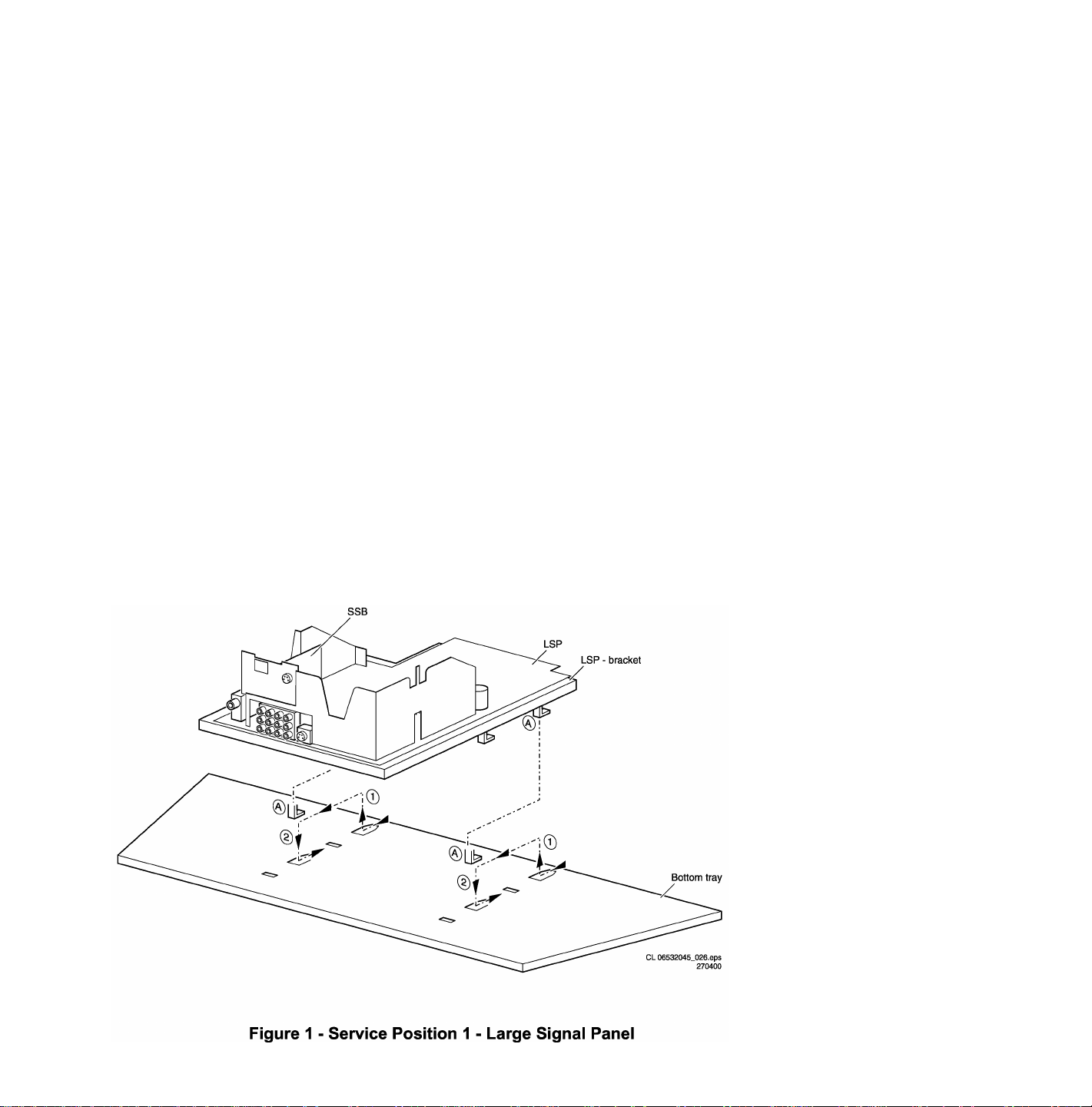
Service Position 1 for the Large Signal Panel (LSP)
Position 1: The following service position will provide the best accessibility to the Top Side of the Large Signal Panel:
1. Remove the LSP-bracket from the bottom tray by sliding the bracket backward and then pull the bracket up and out of the
bottom tray.
2. Place the Hooks (A) of the bracket in the first row of fixation holes of the cabinet bottom. In other words reposition the
bracket hooks from position (1) to position (2).
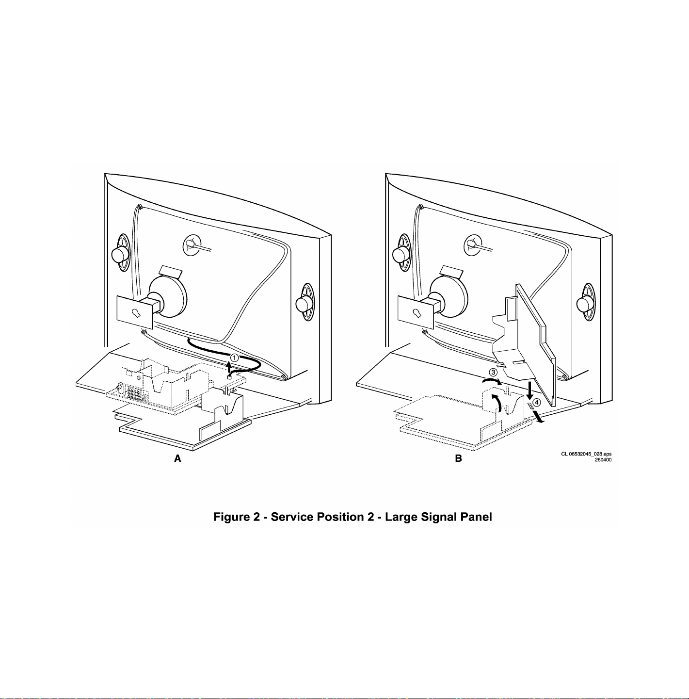
Service Position 2 for the Large Signal Panel (LSP)
Position 2: The following service position will provide the best accessibility to the bottom side (solder side) of the Large Signal
Panel:
1. Disconnect the degaussing coil from the LSP by removing the cable from connector 0211 (1).
2. Release the wiring from their clamps, to enable for repositioning the LSP.
3. Turn the chassis tray 90 degrees counter clockwise (2).
4. Flip the tray with the rear I/O panel toward the CRT (3).
5. Place the hook of the tray into the slot (4) at the right side of the cabinet bottom (4) and slide the chassis tray forward.

Service position for the Small Signal Board (SSB)
There is not a predefined service position for the bottom (B-) side of the SSB. All relevant test points can be accessed in both
LSB service positions.
If IC's must be replaced: take the complete panel out of the SIMM-connector.
1. Put the Large Signal Panel in service position 1 (as described above).
2. Release the 2 metal clamps at both sides of the SIMM-connector and the complete SSB can be taken out. It 'hinges' in the
SIMM-connector.
Access to the Top Control Panel
1. Remove the two screws that hold the panel to the cabinet back.
2. Slide the board backward (release it from the front hinge).
3. The board can easily be lifted out of the bracket after releasing the two clamps on the connector side.

Access to the Side I/O Panel
1. Remove the two screws.
2. Remove the complete Side I/O-assembly.
3. Release the two clamps then lift the board out of the bracket.
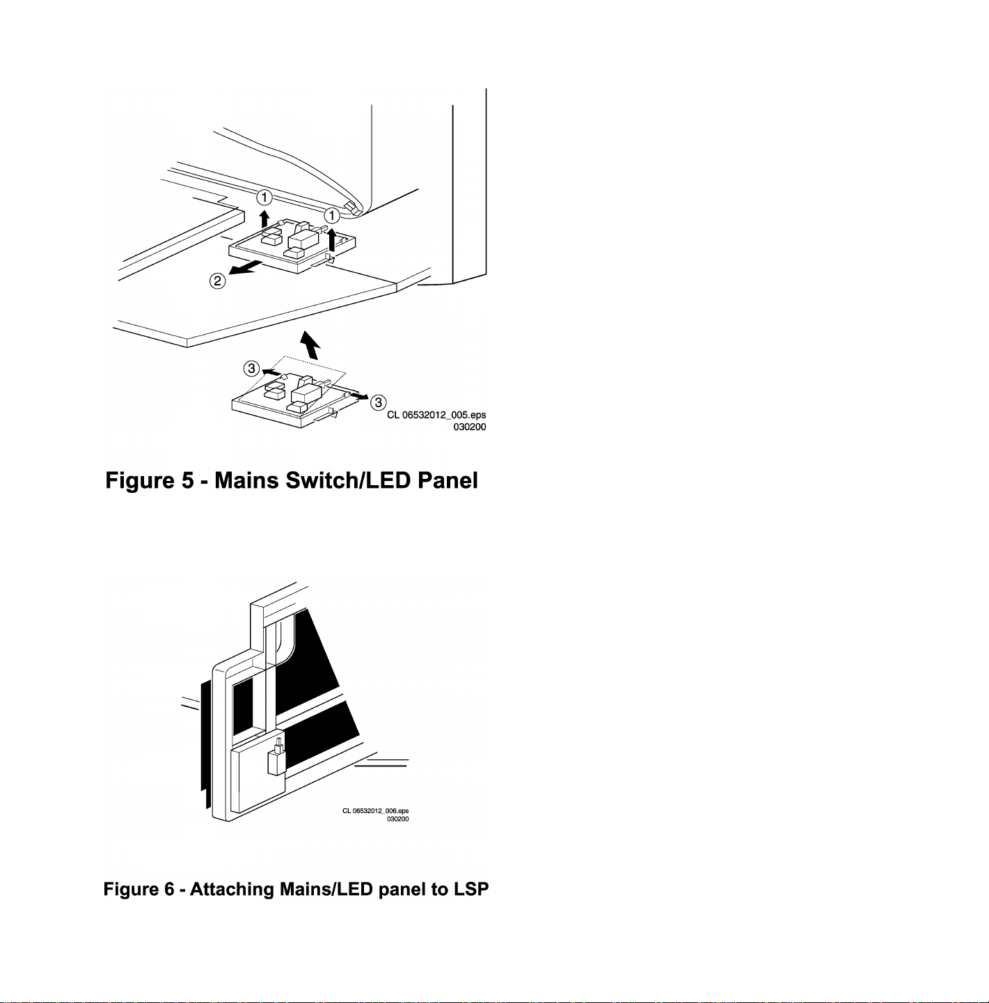
Access to the Mains Switch/LED Panel
1. Release the two clamps (1) by pulling them upward.
2. While pulling upward on the clamps, slide the complete assembly backward (2).
3. If it is necessary to remove the board, release the two clamps at the sides of the bracket and lift the board out (3).
1. To perform measurements, the panel may be attached to the LSP bracket (4).
 Loading...