

Philips 27-REAL FLAT STEREO TV 27PT6341, 27-REAL FLAT STEREO TV 27PT6341-07B, 27PT6341/07 User Manual
1
Thank you for choosing Philips.
Need help fast?
Read your Quick Use Guide and/or
Owner's Manual first for quick tips
that make using your Philips product
more enjoyable.
If you have read your instructions
and still need assistance,
you may access our online help at
www.philips.com/usasupport
or call
1-888-PHILIPS (744-5477)
while with your product
(and Model / Serial number)
S
T
O
P
TRODUC
TION
Welcome/Registration of Your TV
. . . . . . . . . . . . . . . . . . . . . .
. . . . . . . . . . . . . . . . . . . . . . . . . . .
4
. . . . . . . . . . . . . . . . . . .
. . . . . . . . . . . . . . . .
. . . . . . . . . . . . . . . . . . . . . . . . . . . . . . .
AV(Audio/Video) Input Connection
. . . . . . . . . . . . . . . . . . . . .
8
. . . . . . . . . . . . . . . . . . . . . . . . . . . . . . . . .
9
. . . . . . . . . . . . . . . . . . . .
. . . . . . . . . . . . .
AV Output Jacks
. . . . . . . . . . . . . . . . . . . . . . . . . . . . . . . . . . . .
. . . . . . . . . . . . . . . . . .
. . . . . . . . . . . . . . . . . . . . . . . . . . . . . . . . . . .
Tuner Mode Control
. . . . . . . . . . . . . . . . . . . . . . . . . . . . . . . .
Auto Program
. . . . . . . . . . . . . . . . . . . . . . . . . . . . . . . . . . . . .
. . . . . . . . . . . . . . . . . . . . . . . . . . . . . . . . . . . . . . .
. . . . . . . . . . . . . . . . . . . . . . . . . . . . . .
. . . . . . . . . . . . . . . . . . . . . . . . . . . . . . .
Timer Control
. . . . . . . . . . . . . . . . . . . . . . . . . . . . . . . . . . . . .
20
Timer Control - Activate
. . . . . . . . . . . . . . . . . . . . . . . . . .
20
Timer Control - Start or stop time
. . . . . . . . . . . . . . . . .
Timer Control - Start on a specific channel
. . . . . . . . . . .
22
Timer Control - Using display
. . . . . . . . . . . . . . . . . . . . . .
. . . . . . . . . . . . . . . . . . . . . . . . . . . . . . . . . . . . . .
23
4:3 Expand Format Control
. . . . . . . . . . . . . . . . . . . . . . . . . . .
23
. . . . . . . . . . . . . . . . . . . . . .
24
. . . . . . . . . . . . . . . . . . . . . . . . . .
25
. . . . . . . . . . . . . . . . . . . . . . . . . . . . . . . . . . . .
26
. . . . . . . . . . . .
27
. . . . . . . . . . . . . . . . . . . . . . . . . . . . . . . . . . . . . .
28
TV Ratings
. . . . . . . . . . . . . . . . . . . . . . . . . . . . . . . . . . . . . . . . .
29
. . . . . . . . . . . . . . . . . . . . . . . . . . . . . . . . . . . . .
. . . . . . . . . . . . . . . . . . . . . . . . . . . . . . . . . . .
. . . . . . . . . . . . . . . . . . . . . . . . . . . . . . . . . . . . . . . . .
Auto Picture
. . . . . . . . . . . . . . . . . . . . . . . . . . . . . . . . . . . . . .
Auto Sound
. . . . . . . . . . . . . . . . . . . . . . . . . . . . . . . . . . . . . . . .
. . . . . . . . . . . . . . . . . . . . . . . . . . . . . . . . . . . .
A/CH (Alternating Channels) .
. . . . . . . . . . . . . . . . . . . . . . . .
. . . . . . . . . . . . . . . . . . . . . . . . . . . . . . . . . . . . . . . . . .
. . . . . . . . . . . . . . . . . . . . . . . . . . . . . . . . . .
Troubleshooting Tips
. . . . . . . . . . . . . . . . . . . . . . . . . . . . . . . .
. . . . . . . . . . . . . . . . . . . . . . . . . . . . . . . . . . . . . .
. . . . . . . . . . . . . . . . . . . . . . . . . . . . . . . . . . .
. . . . . . . . . . . . . . . . . . . . . . . . . . . . . . . . . . . . . . . . . . .
CONTENTS
AutoLock
Auto
to your preference. The five pre-set controls (Personal, Movie,
Auto
to your preference. The four pre-set controls (Personal, Voice,
the sound of the program you are watching (Pg. 19).
the TV memory. Channel Edit makes it easy to limit or expand the
allows the viewer to read TV program
allows you to store and surf up to 10 channels
you choose for each colored button on the remote control
allows
the viewer to set a timer to automatically turn
the TV off
after a period of time (
As an Energy Star® Partner, Philips Consumer
Electronics has determined this product meets
the Energy Star® guidelines for energy efficiency
AutoPicture, AutoSound, and Incredible Surround are
trademarks of Philips Consumer Electronics Company.
: After the FCC wi
thdraws all analog signals in 2009,
your analog TV will require a digital to analog converter box
to convert digital signals to analog so
that you can continue
to receive broadcast
Registering your model with PHILIPS makes you eligible for all of the valuable benefits listed below, so don't miss out.
Complete and return your Product Registration Card at once, or register online at www.philips.com/usasupport
to ensure:
Return your Product Registration Card or register online at
www.philips.com/usasupport today to get the very most from your purchase.
Visit our World Wide Web Site at http://www.philips.com/usasupport
Congratulations on your purchase,
and welcome to the “family!”
Dear PHILIPS product owner:
Thank you for your confidence in PHILIPS.You’ve selected one of
the best-built, best-backed products available today.We’ll do everything in our power to keep you happy with your purchase for many
years to come.
As a member of the PHILIPS “family,” you’re entitled to protection
by one of the most comprehensive warranties and outstanding
service networks in the industry.What’s more, your purchase guarantees you’ll receive all the information and special offers for which
you qualify, plus easy access to accessories from our convenient
home shopping network.
Most importantly, you can count on our uncompromising commitment to your total satisfaction.
All of this is our way of saying welcome - and thanks for investing
in a PHILIPS product.
P.S. To get the most from your PHILIPS purchase, be
sure to complete and return your Product Registration
Card at once, or register online at:
www.philips.com/usasupport
For Customer Use
Enter below the Serial No. which is located on the rear of the cabinet. Retain this
information for future reference.
Model No.__________________________
Serial No. ________________________
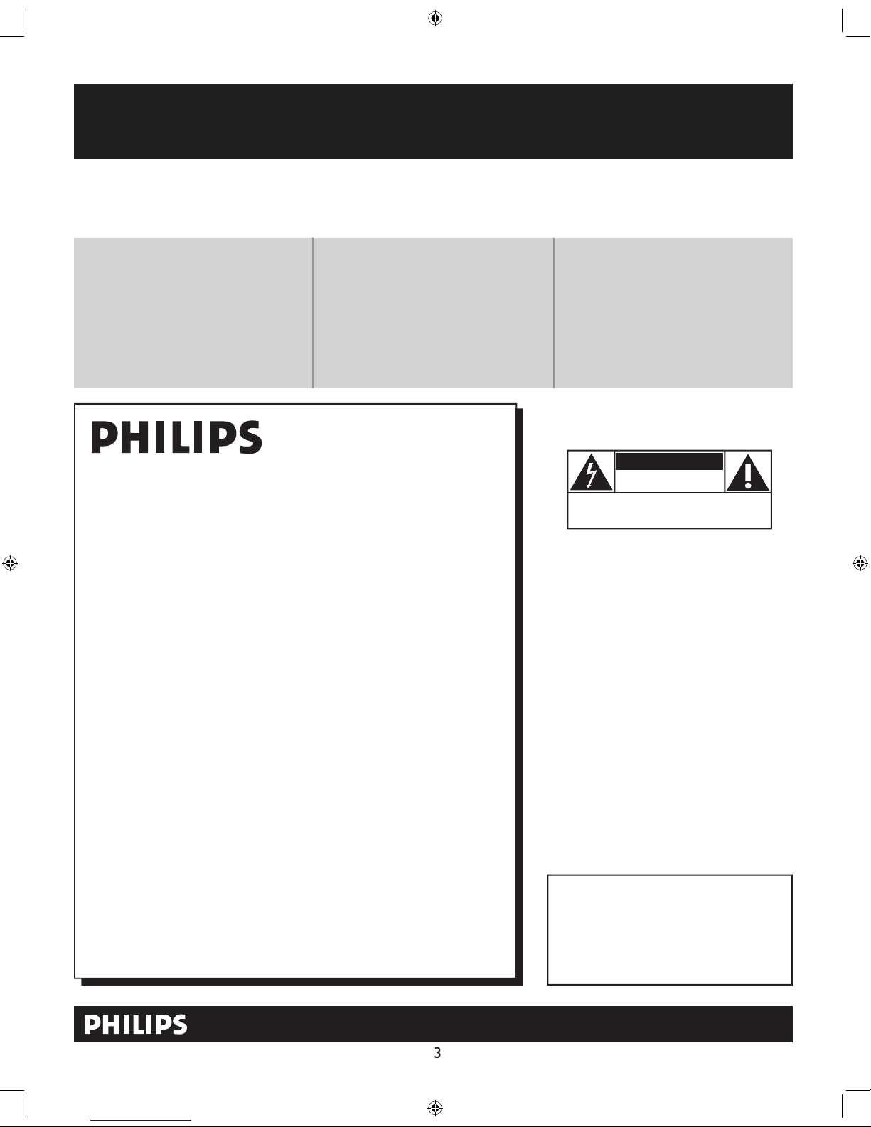
Know these
safetysymbols
This “bolt of lightning” indicates unin-
sulated material within your unit may
cause an electrical shock. For the safety of
everyone in your household, please do not
remove product covering.
The “exclamation point” calls atten-
tion to features for which you should
read the enclosed literature closely to prevent operating and maintenance problems.
WARNING: To reduce the risk of fire or
electric shock, this apparatus should not be
exposed to rain or moisture and objects
filled with liquids, such as vases, should not
be placed on this apparatus.
CAUTION: To prevent electric shock,
match wide blade of plug to wide slot, fully
insert.
ATTENTION: Pour éviter les choc électriques, introduire la lame la plus large de la
fiche dans la borne correspondante de la
prise et pousser jusqu’au fond.
CAUTION
RISK OF ELECTRIC SHOCK
DO NOT OPEN
CAUTION: TO REDUCE THE RISK OF ELECTRIC SHOCK, DO NOT
REMOVE COVER (OR BACK). NO USER-SERVICEABLE PARTS
INSIDE. REFER SERVICING TO QUALIFIED SERVICE PERSONNEL.
t
s
*Proof of
Purchase
Returning the enclosed card guarantees
that your date of purchase will be on file,
so no additional paperwork will be
required from you to obtain warranty
service.
*Product Safety
Notification
By registering your product, you'll receive
notification - directly from the manufacturer - in the rare case of a product
recall or safety defect.
*Additional Benefits
Registering your product guarantees that
you'll receive all of the privileges to
which you're entitled, including special
money-saving offers.
4
Keep these instructions.
4.
Follow all instructions.
Do not use this TV near water.
Clean only with a dry cloth.
with the manufacturers instructions.
Do not install near any heat sources such as radiators, heat
Do not defeat the safety purpose of the polarized or grounding-
type plug. A polarized plug has two blades with one wider than the
When the provided plug does not fit into your outlet, consult an
electrician for replacement of the obsolete outlet.
they exit from the apparatus.
specified by the manufacturer, or sold with the TV
When a cart is used, use caution when moving
the cart/TV combination to avoid injury from tip-over.
Refer all servicing to qualified service personnel. Servicing is
authorities or the Electronic Industries Alliance: www.eiae.org
Damage Requiring Service - The TV should be serviced by qualified
service personnel when:
A
Objects have fallen, or liquid has been spilled into the TV; or
The TV has been exposed to rain; or
The TV does not appear to operate normally or exhibits a
The TV has been dropped, or the enclosure damaged.
- All televisions must comply with recommended
• Do not compromise these design standards by applying excessive
• Also, do not endanger yourself, or children, by placing electronic
equipment/toys on the top of the cabinet. Such items could
damage and/or personal injury.
g - The TV should be mounted to a
wall or ceiling only as recommended by the manufacturer.
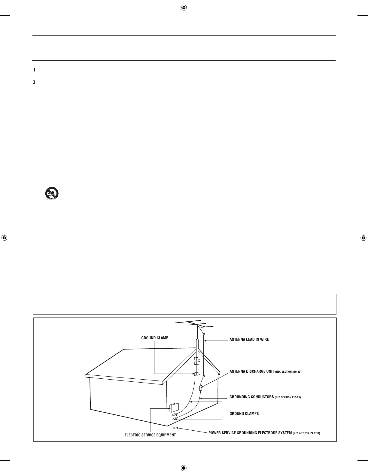
- An outdoor antenna should be located away from
- If an outside antenna is
as to provide some protection against voltage surges and built up static
Section 810 of the National Electric Code, ANSI/NFPA No. 70-
the mast and supporting structure, grounding of the lead-in wire to
an antenna discharge unit, size of grounding connectors, location
Object and Liquid Entry
- Care should be taken so that
through openings.
a)
Warning: To reduce the risk of fire or electric shock, this
apparatus should not be exposed to rain or moisture and objects
filled with liquids, such as vases, should not be placed on this
apparatus.
- To prevent battery leakage that
• Install all batteries correctly, with + and - aligned as marked on
the unit.
• Do not mix batteries (old and new or carbon and alkaline, etc.).
• Remove batteries when the unit is not used for a long time.
This reminder is provided to call the CATV system installer's attention to Article 820-40 of the NEC
that provides guidelines for proper grounding and, in particular, specifies that the cable ground shall be connected to the grounding system of the
75
75‰
L
R
S-VIDE
O
VIDE
O
AUDI
O
CV
IAV out
Y
Pb
Pr
AV in
1
Back of TV
Cable signal
coming from
Cable Company
Jack Panel Back of TV
75
1
2
75‰
L
R
S-VIDE
O
VIDE
O
AUDI
O
CV
IAV out
Y
Pb
Pr
AV in
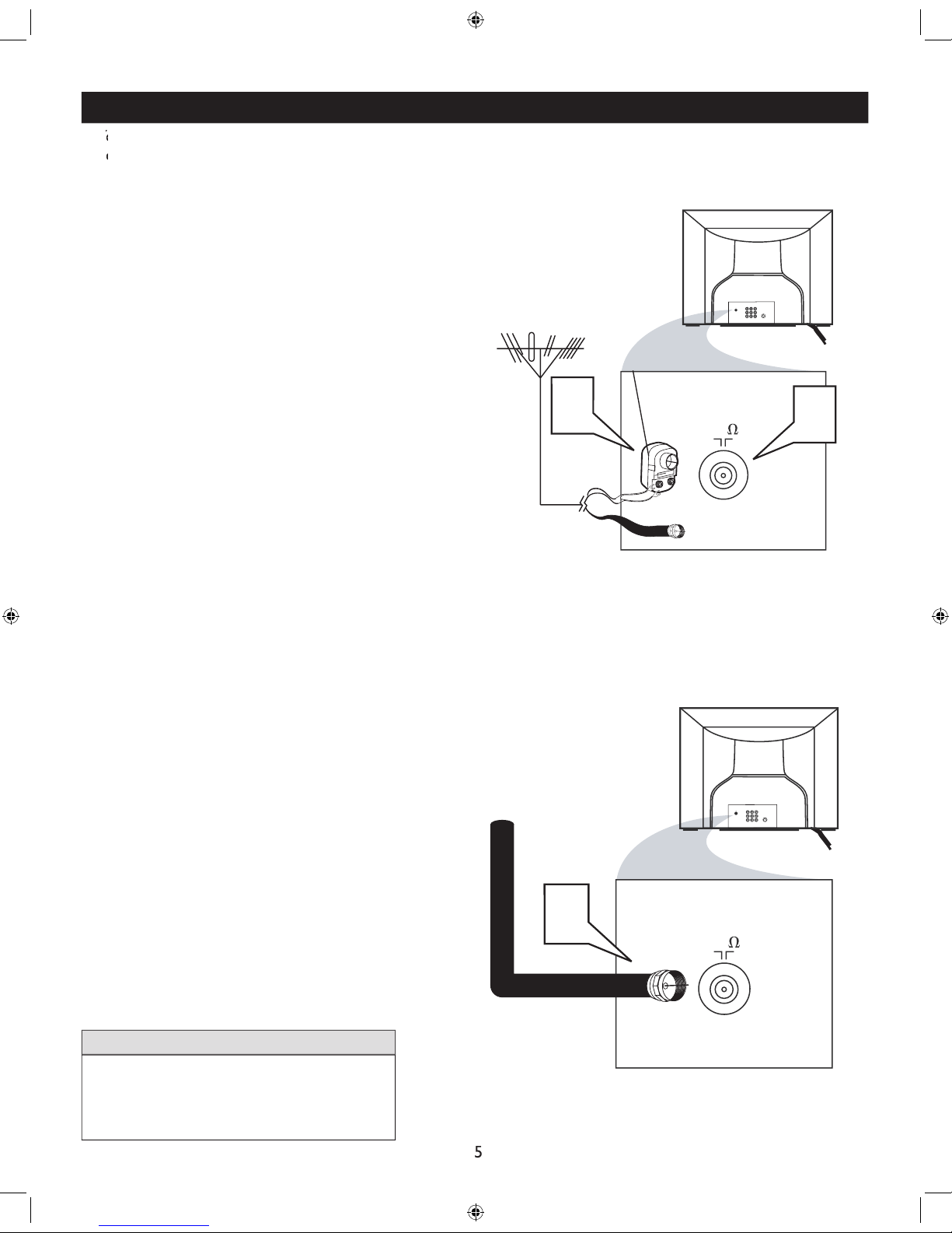
Antenna Connection
300 to 75Ω
Adapte
r
Combination
VHF/UHF Antenna
(Outdoor or Indoor)
Twin Lead
Wire
Round Cable
75Ω
Back of TV
Direct Cable Connection
75Ω Round
Coaxial Cable
BASIC ANTENNA AND CABLE CONNECTIONS
After using the Auto Program Control, press the
1
(75 ohm) then you are ready
to connect to the TV.
wires to the screws of a 75 ohm adapter.
2
TV.
If you have a Cable Converter Box : Connect
the OUT (put) plug from the Converter to the
Ω
Ω
Ω
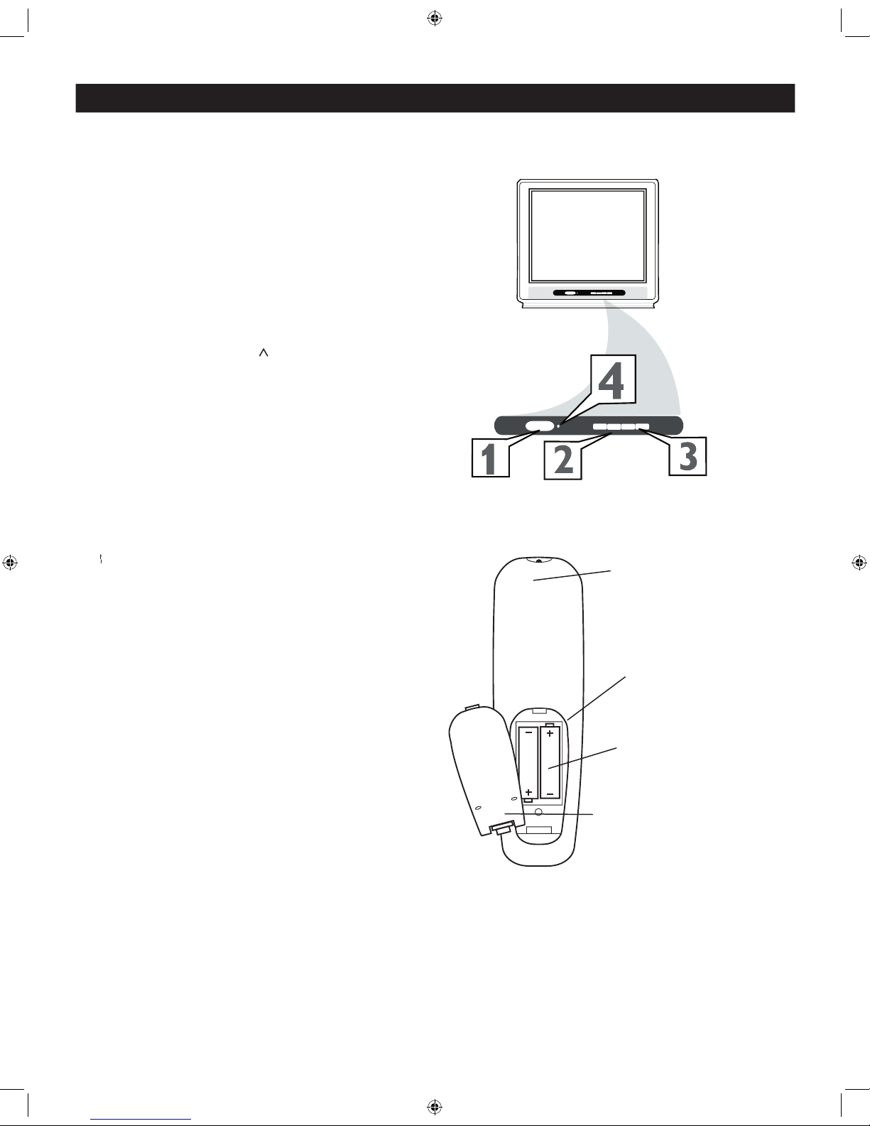
BASIC TV AND REMOTE CONTROL OPERATION
1
to turn the TV
2
to increase
the sound level, or the
VOLUME - button
to
will display the on-screen menu. Once in the
or selections.
3
or > > or
4
toward the
operating the TV with the remote.
1
at
the back of the remote.
2
3
POWER
VOLUME
+
>
<
CHANNEL
POWER
VOLUME
-
+
>
<
CHANNEL
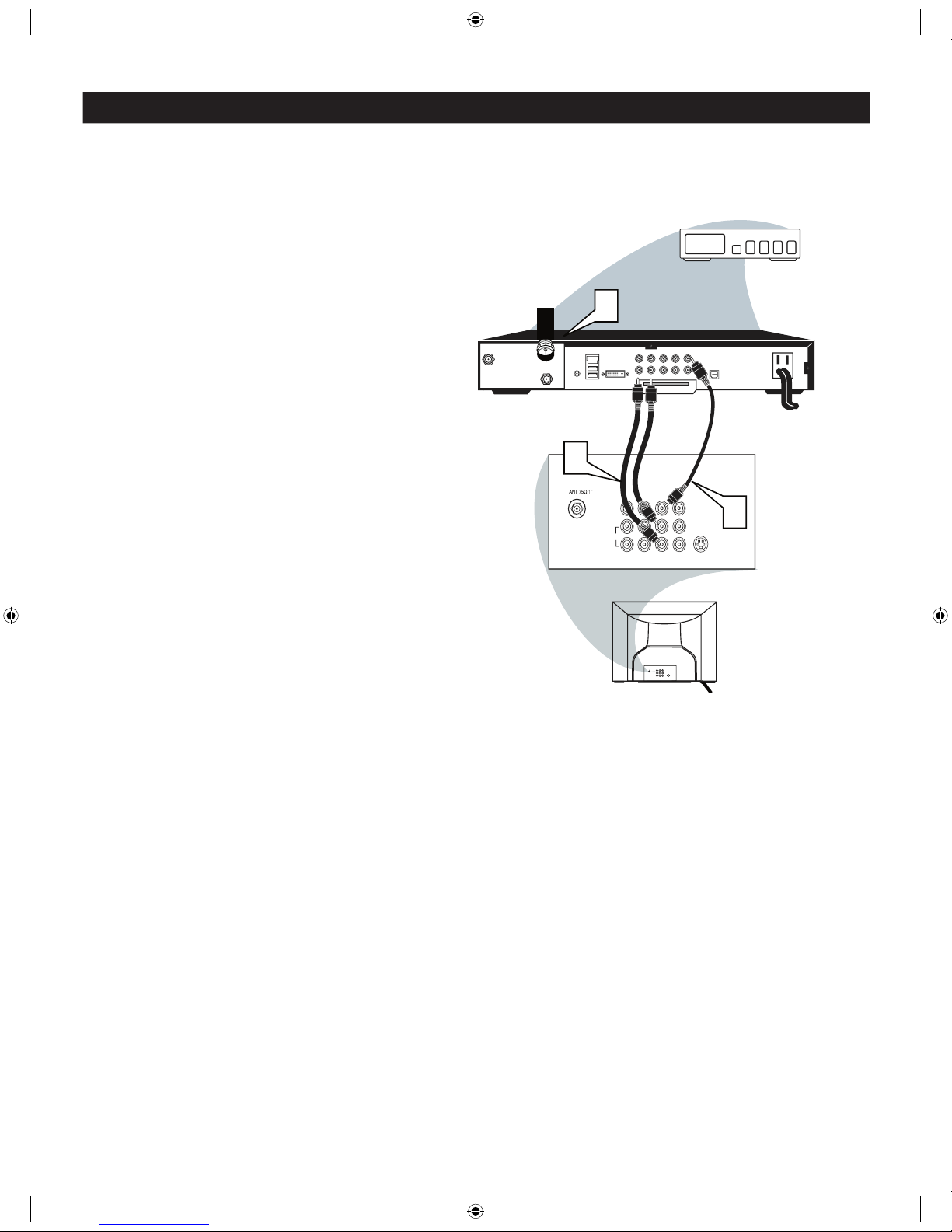
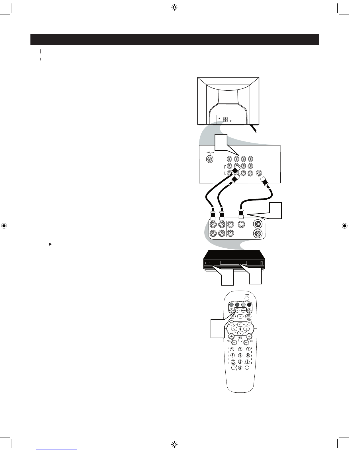
CABLE BOX CONNECTIONS
f your cable signal uses a cable box or decoder, follow the steps below to complete the connection.
1
to the signal IN(put) plug at the back of
the Cable Box.
2
end of the cable to the Video
(or ANT,
your cable box may be labeled differently)
jack
on the cable box and the other end to the
AVI Video Input on the TV.
3
of the Audio Left and Right
to the left and right Audio Out L
other end to the AV In Audio L & R Input jacks
on the TV.
Use the
AV
button on the TV remote control
to tune to the
AV
channel or the cable box
L/Mono
VIDEO
S-VIDEO
CVI
Y
Pb
Pr
AUDIO
TO
TV/VCR
CABLE
IN
IR
USB
DVD-D OUT
AUDIO IN
SPDIF
VIDE
O
IN OUT
S-VIDEO
R L
AUDIO OUT
TV
PASSCARD
Y Pb Pr
OPTICAL
SPDIF
1
2
24
3
75‰
L
R
S-VIDEO
VIDE
O
AUDI
O
CV
IAV out
Y
Pb
Pr
AV in
AV1
In
Monitor
out
Cable Signal IN
from the Cable
Company
Cable Box with A/V Outputs
Jack Panel Back of TV
Audio Cables
L (White) & R (Red)
Video Cable
(Yellow)
Cable Box (w/Audio/Video Outputs):
R
AV2
In
Pb
Y
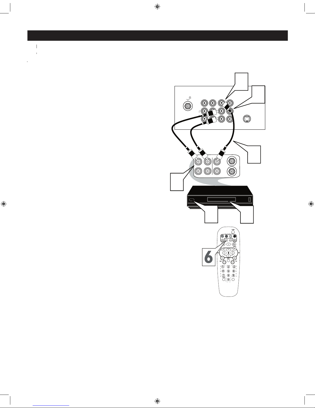
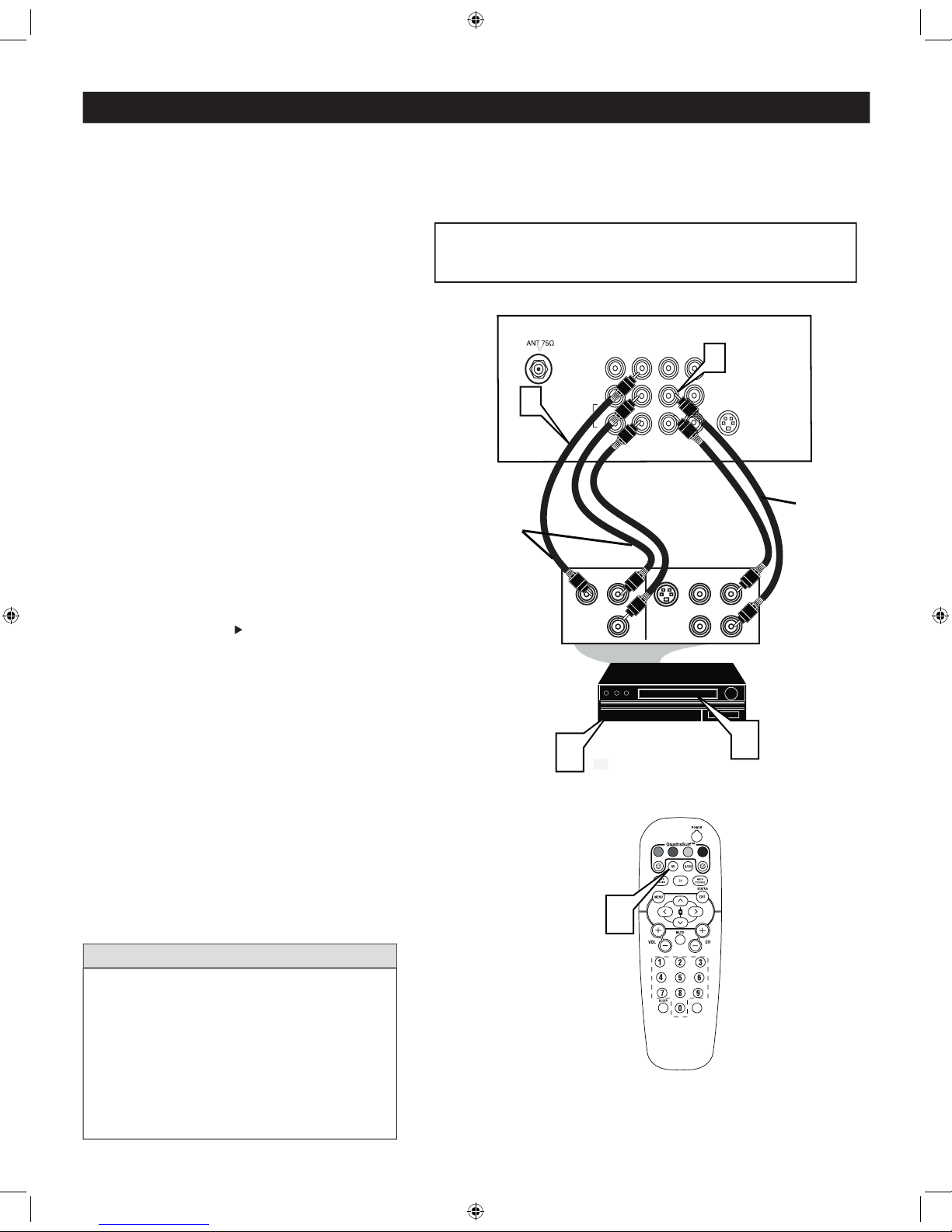
AV (AUDIO/VIDEO) INPUT CONNECTION
Jacks located at the back of the TV.
Jacks located at the back of the TV.
1
VIDEO AV In jack on the back of the TV.
2
to the AUDIO (left and right) AV In
jacks on the rear of the TV.
3
to the
VIDEO OUT jack at the back of the VCR.
4
to the
AUDIO (left and right) OUT
jacks at the rear of the VCR.
5
Turn the VCR (accessory device) and the
TV on.
6
on the remote control
to select the AV Channel. AV will appear on
the upper left corner of the TV screen.
7
With the VCR (or accessory device) ON and
a prerecorded tape (CD, DVD, etc.) inserted,
to view the tape
on the television.
222
75
S-VIDEO
ANTENNA
OU
T
ANTENNA
IN
VIDE
O
AUDIO
IN
IN
OU
TOUT
LR
5
3
7
Y
Pb
2
1
Video Cable
(Yellow)
Audio Cables
(Red & White)
Back of TV
Back of Typical VCR
VCR
with
Audio/Video Outputs
VOL
VIDEO
AUDI
O
R
Pr
L/Mono
4
CVI
AV1 In
Monitor
out
AV2 In
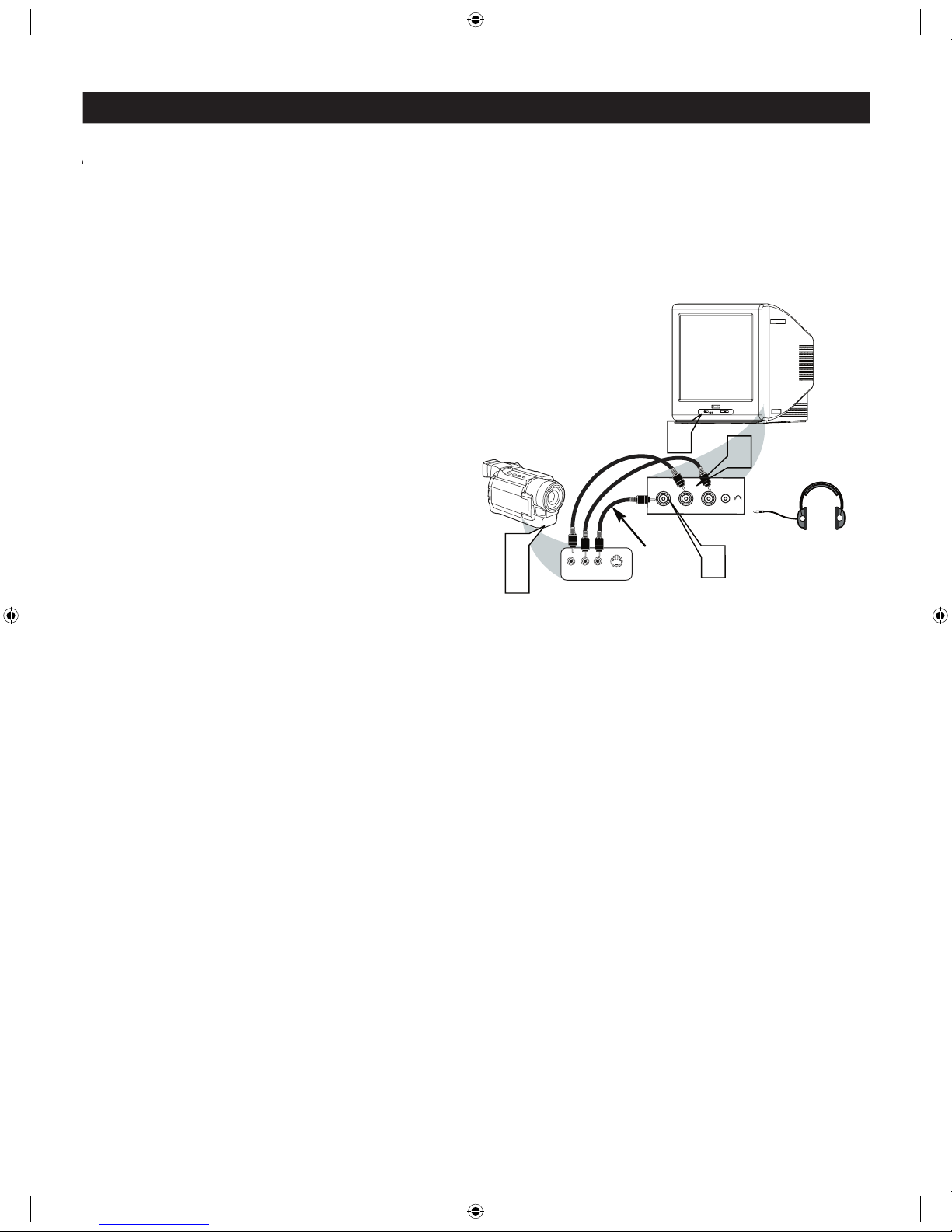
SIDE AV CONNECTIONS
A
A
button on the remote control to tune these inputs.
1
from
the Video output on the Camera (or accessory
the SIDE (or FRONT) of the TV.
2
jack on the SIDE (or FRONT)of the television.
Connect one end of the
audio cable from the Audio Out jack on the
of the television.
3
Turn the TV and the accessory device
.
4
on the
5
accessory device (camera, gaming unit, etc.).
S-VIDEO
VIDEOAUDIO
LEFT RIGHT
3
1
2
3
5
Side AV Inputs:
Side Jack
panel of TV
Vide
o
Cable
Audio
Cables
Jack Panel of Accessory Device
Optional
Headphones
VIDE
O
AUD
IO
L
R
S-VIDEO (S-VHS) INPUT CONNECTIONS
VHS VCR (video cassette recorder) tapes than the normal antenna picture connections.
The accessory device must have an S-VIDEO
1
to the S-VIDEO jack to the back of the TV.
2
to the S-VHS (S-Video) OUT jack on
the back of the VCR. Connect the other end
of the AUDIO (red and white) CABLES to the
AUDIO (left and right) OUT jacks on the rear
of the VCR.
3
Turn the VCR and TV on.
4
on the remote control
to scroll the channels until SVHS appears in the
5
video tape in the VCR and
press the PLAY
button
75‰
L
R
S-VIDE
O
VIDE
O
AUDI
O
CV
IAV out
Y
Pb
Pr
AV in
L/Mono
VIDEO
S-VIDEO
CV
I
Y
Pb
Pr
AUDI
O
AV
1 In
R
ANTENNA
OUT
ANTENNA
IN
VIDEO
AUDIO
IN
IN
OUTOUT
LR
S-VHS OUT
3
2
5
1
VOL
Monitor
out
AV2I
n
4
Audio Cables
S-Video
VCR or External
Accessory Device
COMPONENT VIDEO (CVI) INPUT CONNECTIONS
1
Video OUT
jacks from the DVD player (or
on the TV. When using the Component Video
AV in Video Jack.
2
to the Audio (left and right) output
jacks on the rear of the accessory device to the
Audio (L and R) AV Input Jacks on the TV.
3
Turn the TV and the DVD (or digital
accessory device) ON.
4
on the remote control
to scroll the channels until CVI appears in the
5
button on the DVD Player.
The description for the component video
vary, the letters b and r stand for blue and red
VIDEO
S-VIDEO
CVI
Y
Pb
Pr
AV
1 In
R
S-VIDEO
OUT
OUT
OUT
L
R
AUDIO
VIDEO
COMP VIDEO
Y
Pb
Pr
3
5
1
Component
Video Cables
(Green, Blue,
Red)
Audio
Cables
(Red &
White)
Accessory Device
Equipped with
Component Vide
o
Outputs
Back of TV
VOL
L/Mono
AUDIO
R
2
AV2 In
Monitor
out
4
The CVI connection will dominate over the AV1 in Video Input.
When a Component Video Device is connected as described, it is best
not to have a video signal connected to the AV1 in Video Input jack.
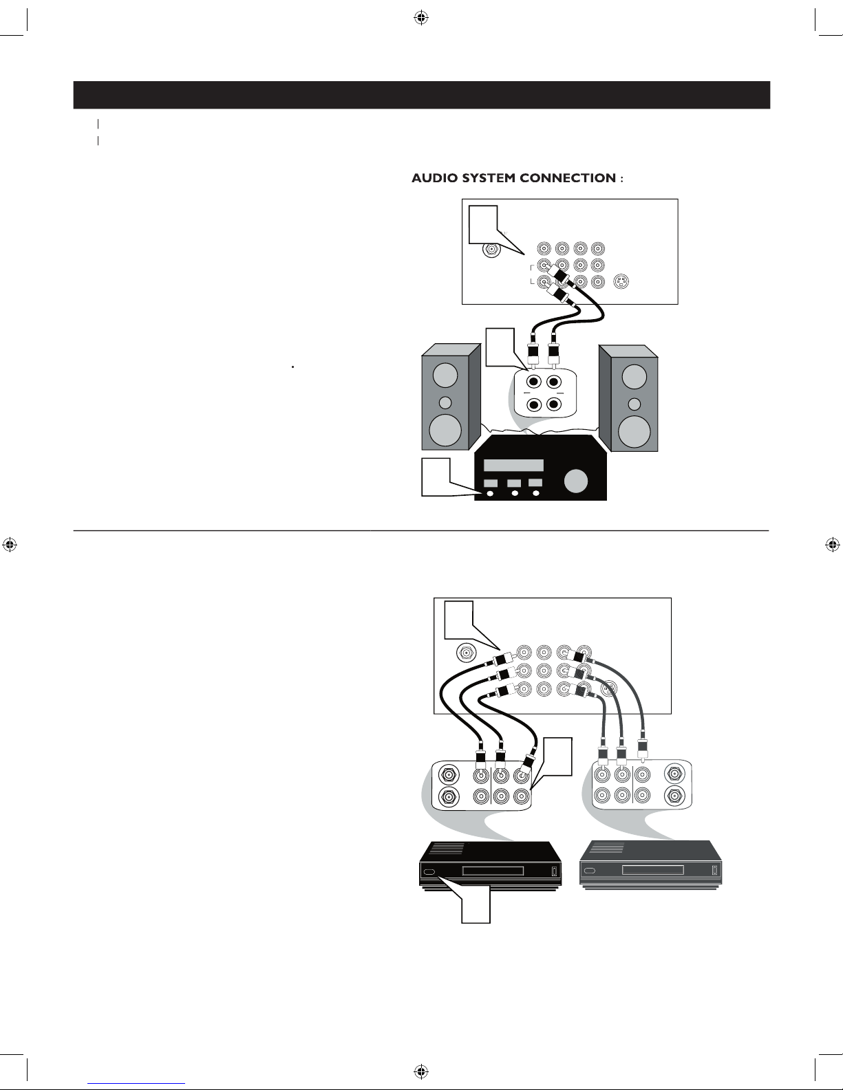
AV OUTPUT CONNECTIONS
AUDIO SYSTEM CONNECTION :
1
AUDIO
jacks on the TV to the R and L audio
2
Turn the TV and audio system on.
To
adjust the volume of the audio system, you
will need to change the volume at the external
audio system
not the television
Refer to page 8 for the proper hookup of the
first VCR. Follow the instructions on how to tune to
the AV1 channel to view a pre-recorded tape.
The following steps allow you to connect a second VCR
to record the program while watching it.
1
the other end to the VIDEO IN plug on
the second VCR.
2
Audio cable
from the
AV Out AUDIO L
and
plugs on the TV to the
AUDIO IN
3
Turn the Second VCR ON
tape and its ready to record what’s being
viewed on the TV screen.
A
U
X
/
T
V
I
N
P
U
T
P
H
O
N
O
IN
P
U
T
R
L
2
L/Mono
Monito
r
Ou
t
VIDE
O
S-VIDE
O
CVI
Y
Pb
Pr
AV1
In
AUDI
O
1
1
R
Back of TV
Audio Cables
(Red and White)
AUDIO SYSTEM CONNECTION:
CVI
AV2
In
AUDIO SYSTEM CONNECTION :
Y
Pb
Pr
ANTENNA
OU
T
ANTENNA
IN
VIDE
O
AUDI
O
IN
IN
OU
TOUT
LR
ANTENNA
OU
T
ANTENNA
IN
VIDE
O
AUDI
O
IN
IN
OUT OUT
RL
1
2
3
Monitor
ou
t
S-VIDE
O
CV
I
AV
1 In
R
Back of TV
Audio Cables
1st VCR
(refer to panel 4 for
proper connection)
Vide
o
Cable
2nd VCR with Audio and
Video Input Jacks
AUDIO SYSTEM CONNECTION:
L/Mono
VIDEO
AUDI
O
R
AV2 In
 Loading...