

Philips 32PT9005D-37B, 27PT9015D-37B User Manual
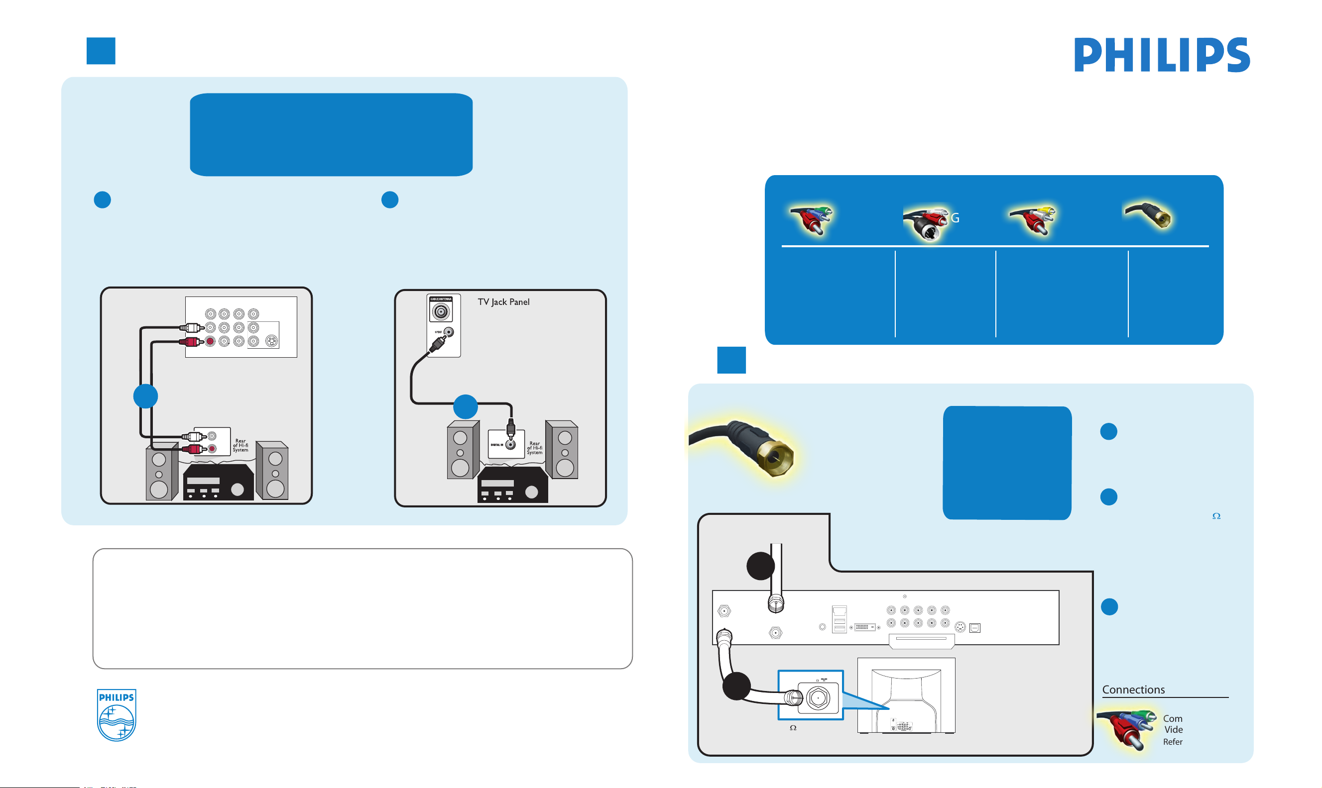
Connecting Hi-fi System or External Speakers to TV
3
How t
o
SPDIF (Sony and Philips Digital Interconnect Format)
is highly recommended for high quality digital
surround sound output.
Connect red/while audio cables from the TV
A
monitor output jacks to the rear of hi-fi system
or external speakers.
AV1 in
Y
Pb
Pr
T VIDEO INPUT
AV2 in
TV Jack Panel
AUDIO
VIDEO
L/Mono
R
Monitor out
COMPONEN
A
TV
IN
Need more help?
User manual:
Check the user ma ual that came with
Online help
:
n
www.p4c.philips.com or
w.usasupport.philips.com
ww
S-VIDEO
Better
your
OR
TV.
Connect audio cable from the SPDIF jack on the
B
rear of the TV to the DIGITAL IN jack on the
rear of the hi-fi system or external speakers.
B
mak
e
Use this guide to achieve the optimal connection for each of
the best
connection
our components
y
.
TV can support these different types of cable connection. Please check your
device to see which one applies.
Connection Basics
Better Good
Component Video
Input (CVI)
Provides superior picture
quality by separating the
green, blue and red
luminance signals. Typically
used with red/white
1
audio cables.
Connecting Set-Top Box to TV
S-Video
Supplies a better picture
than RF and Composite
connections. Used with
red/white audio cables.
Composite Audio/Video
Separate video (yellow) and
audio (red/white) cables that
provide a basic connection from
the cable box and other devices.
Note
: The color of audio inputs
may differ, e.g. red/white or
red/black.
Basic
RF Cable
RF
Provides a basic
connection
Basic
RF
Provides a basic
connection
for antenna or cable.
Provides both audio
and video.
Connect RF cable
A
from wall to input at
the back of the cable
box.
for antenna or cable.
Provides both audio
and video.
Cable Signal IN
C
from Cable Company
A
Back of Cable Box
SPDIF
IN
Y Pb Pr
VIDEO
OUT
S-VIDEO
OPTICAL
SPDIF
TV
PASSCARD
AUDIO IN
R L
AUDIO OUT
-
TO
TV/VCR
CABLE
IN
IR
DVD-D OUT
USB
Use second RF cable to
B
connect the cable box
to the TV input (75 ).
Note: This connection gives
mono sound. For stereo
sound use also composite
audio/video connection
(Refer to panel 2).
Set output switch
C
on set-top box to
CH 3 or 4 and tune
TV to same channel.
Basic
2005 © Koninklijke Philips Electronics N.V.
All
rights reserved.
3139
125 35352
B
75
75 Input
TV
Other Possible
Connections
Monitor out
Component
Video
Refer to panel 2.

Connecting Input Device to TV (eg. DVD player, Digital Recorder, VCR, Video Camera, Games Console)
2
Component Video Input
Component Video
Input (CVI)
Provides superior picture quality
by separating the green, blue and
red luminance signals. Typically
used with red/while audio cables.
Insert Component
A
Video connectors into
their corresponding
jacks on both DVD
player/DVD recorder
and TV (sometimes
labeled Y, Pb and Pr).
Turn on TV and DVD
C
player/DVD recorder.
Press the AV button
on the remote control
until CVI appears on
TV screen
.
Note: When using CVI, it is best not to connect a video
signal to the other AV input on the TV.
Connect red/white
B
audio cables to the
audio output jacks
on DVD player/DVD
recorder and audio
AV inputs on TV.
Insert a pre-recorded
D
DVD into DVD player/
DVD recorder and
press PLAY to verify
correct connection.
Better
Monitor out
TV
Back of
DVD Player/Recorder
POWE
FORMAT CLOCK SLEEP GUIDE
CC INF
P
AV SA
AUTO
A/D
SOUND
MENU OK
MUT
E
VOL CH
1 2 3
4
5 6
7 8 9
H
A/C
0
R
O
AUTO
PICTUR
E
Remote
Cont
A
C
rol
TV Jack Panel
Monitor out
VIDEO
L/Mono
R
COMPONEN
COM
P VIDEO
Y
FORMAT CLOCK SLEEP GUIDE
AV2 in
AV1 in
T VIDEO INPUT
S-VIDEO
Pb
OUT
Pr
P CC INFO
AV SA
AUTO
A/D
SOUND
AV Buttons
S-Video
TV Jack Panel
B
Good
S-Video
Supplies a better picture
than RF and Composite
connections. Used with
red/white audio cables.
Monitor out
TV
AUDIO
VIDEO
L/Mono
R
Monitor out
COMPONEN
B
VCR
AUDIO
VIDEO
R
OUT
OUT
AUTO
PICTUR
L
OR
Connect S-Video
A
cable to S-Video input
on back of TV and
S-Video output on
back of VCR
Turn on TV and VCR.
C
Press the AV button
.
on the remote control
E
until S-Video appears
on TV screen
.
Connect audio cables
B
(red/white) to audio AV
inputs on back of TV and
Audio outputs on back
of VCR.
Insert pre-recorded
D
videotape into VCR and
press PLAY to verify
correct connection.
Note: When you connect S-Video and AV2 at the same time,
you can only hear sound coming from S-Video.
S-Video will dominate over the Video of AV2.
Back of
C
Remote
Control
FORMAT CLOCK SLEEP GUIDE
CC INF
P
AV SA
AUTO
A/D
SOUND
MENU OK
MUT
E
VOL CH
1 2 3
4
5 6
7 8 9
H
A/C
0
L R
AUDIO OUT
POWE
R
O
AUTO
PICTUR
E
CH+ and CH- Buttons
S-VIDEO
VIDEO
OUT
FORMAT CLOCK SLEEP GUIDE
AV SA
AUTO
SOUND
AV Button
AV1 in
Y
Pb
Pr
T VIDEO INPUT
ANT/CABLE
OUT
P CC INFO
A/D
A
OUT
AV2 in
AUTO
PICTURE
S-VIDEO
Composite Audio/Video
Separate video (yellow) and
audio (red/white) cables that
provide a basic connection from
the cable box and other devices.
Note
may differ, e.g. red/white or
red/black.
Connect the video
A
cable (yellow) to the
VIDEO AV input on
back of TV and the
corresponding video
output on back
of VCR
Turn on the TV and
C
VCR. Press the AV
.
button on the remote
control until AV1 or
AV2 appears on TV
.
screen
OR
Basic
Composite Audio/Video
: The color of audio inputs
Connect audio cables
B
(red/white) to audio
AV inputs on back of
TV and the
corresponding audio
outputs (L & R) on
back of VCR.
Insert pre-recorded
D
videotape into VCR
and press PLAY to
verify correct
connection.
TV
Back of
Monitor out
VCR
FORMAT CLOCK SLEEP GUIDE
CC INF
P
AV SA
AUTO
A/D
SOUND
MENU OK
MUT
E
VOL CH
1 2 3
4
5 6
7 8 9
H
A/C
0
POWE
R
O
AUTO
PICTUR
E
B
C
Remote
rol
Cont
TV Jack Panel
L/Mono
AUDIO
R
A
R L
VIDEO
AUDIO OUT
OUT
AV Button
A
COMPONEN
ANT/CABLE
OUT
V1 in
AV2 in
T VIDEO INPUT
P CC INFO
A/D
Monitor out
VIDEO
S-VIDEO
OUT
FORMAT CLOCK SLEEP GUIDE
AV SA
AUTO
SOUND
AUTO
PICTUR
OR
Composite Audio/Video
TV Side Jack Panel
Basic
Composite Audio/Video
S-VIDEO
Connect the video
OR
A
cable (yellow) from the
video output on camera
(or other device) to the
video input (yellow)
located on the side of TV.
Connect audio cables
B
E
(red/white) from audio outputs
on device to audio inputs
(red/white) on the side of TV.
for mono devices,
Note:
device’s audio
output to white audio input
connect only white audio
Separate video (yellow) and
audio (red/white) cables that
provide a basic connection from
the cable box and other devices.
Note
: The color of audio inputs
may differ, e.g. red/white or
red/black.
Turn on TV and the
C
device. Press the AV
button on the remote
control until FRONT /
SIDE appears on TV
screen.
Press PLAY on the
D
device to verify
connection
cable from
on the side of TV.
TV
Video Camera
POWE
FORMAT CLOCK SLEEP GUIDE
CC INF
P
AV SA
AUTO
AUTO
A/D
PICTUR
SOUND
MENU OK
MUT
E
VOL CH
1 2 3
4
5 6
7 8 9
H
A/C
0
R
O
E
Remote
Cont
C
rol
TV Side Jack Panel
A
B
VIDEO
AUDIO
S-VIDEO
LEFT RIGHT
Video Camera Jack Panel
FORMAT CLOCK SLEEP GUIDE
P CC INFO
AV SA
AUTO
SOUND
AV Button
AUTO
A/D
PICTUR
VIDEO
L
AUDIO
R
E
 Loading...