

Philips 27PT5245/37 Schematic
Colour Television
Chassis
Contents Page
1. Technical Specifications, Connections and Chassis Overview 2 - 3
2. Safety & Maintenance Instructions, Warnings and Notes 4 - 5
3. Directions for Use 6 - 22
4. Mechanical Instructions 23
5. Faultfinding and Test point Overview with Waveform Diagram 24 - 32
6. Block Diagram, I2C And Supply Voltage Diagram 33 - 34
7. Electrical Diagrams and PWB’s Diagram PWB
Power Supply (Diagram A1) 35
Line Deflection (Diagram A2) 35
Frame Deflection (Diagram A3) 36
Tuner IF (Diagram A4) 36
Video IF and Sound IF (Diagram A5) 37
Micro controller (Diagram A6) 38
Audio/Video Source Switching (Diagram A7) 39
Audio Processor (Diagram A8) 40
Audio Amplifier (Diagram A9) 40
CRT Panel (Diagram B) 41 41
Side AV (Diagram E) 42 42
Layout Main carrier (part 1 to part 4) 43 - 46
8. Alignments 47 - 50
9. Circuit Description, IC pins description 51 - 58
List of Abbreviations 59 - 60
10. Spare Parts List
© Copyright 2001 Philips Consumer Electronics B.V. Eindhoven, The
Netherlands. All rights reserved. No part of this publication may be reproduced,
stored in retrieval system or transmitted, in any form or by any means, electronic,
mechanical, photocopying, or otherwise without the prior permission of Philips.
Subject to modificationPrinted in NetherlandsPublished by RB 0166 Service PaCE
27VM34 U
1--60
1. Technical Specifications, Connections and Chassis Overview
Index:
1. Technical Specifications.
2. Connections.
3. Chassis Overview.
1.1 Technical Specifications
1.1.1 Reception
Tuning system: PLL
Color systems: NTSC-M
Sound systems: FM-mono & FM-stereo
A/V connections: NTSC 3.58
Channel selections: TV: 2-69,CATV: 2-13,A-W,
Aerial input: 75 OHM, 1VP-P
1.1.2 Miscellaneous
Audio output: ≥6W+6W
Mains voltage: AC110-240V~
Mains frequency: 50 /60 Hz
Ambient temperature: + 5 to + 45 deg. C
Maximum humidity: 90 %
Power consumption: 130W
Standby Power consumption: <4W
1.2 Connections
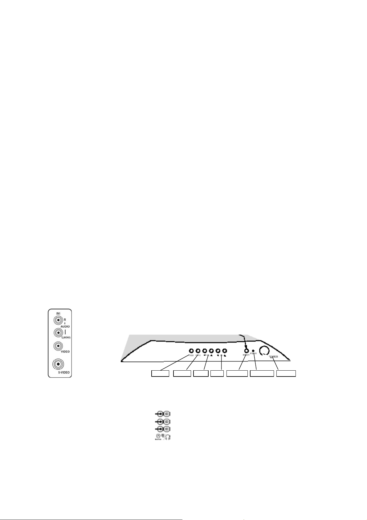
1.2.1 Front (or Side) Connections and Front (or Top) Control
SIDE AV PANEL FRONT PANEL
A/V In (if present)
1 - Video CVBS (1 Vpp / 75 _)
2 - Audio L (0.2 Vrms / 10 k_)
3 - Audio R (0.2 Vrms / 10 k_)
2--60
VO LMEN UAV/ TV CH SENSOR ST AN D BY PO WER
1.2.2 Rear Connections
Monitor Out
1 - Video CVBS (1 Vpp / 75 _) __
2 - Audio L (0.5 Vrms / 1 k_) __
3 - Audio R (0.5 Vrms / 1 k_) __
AV2 In
4 - Video CVBS (1 Vpp / 75 _) __
5 - Audio L (0.5 Vrms / 10 k_) __
6 - Audio R (0.5 Vrms / 10 k_) __
1 - Video CVBS (1 Vpp / 75 _) __
2 - Audio L (0.5 Vrms / 10 k_) _
3 - Audio R (0.5 Vrms / 10 k_) _
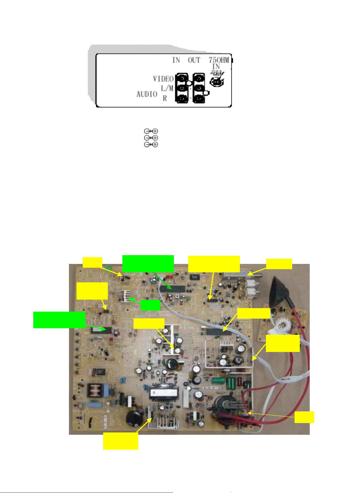
1.3 Chassis Overview
TMP88PS38N
MICROPROCESS
7809
M24C04
EEPROM
TB1240AN
VIDEOPROCESS
7805
TDA2616
4052
SWITCHING IC
TUNER
MSP 3440
TA8427K
FRAME IC
LOT
F6656
POWER IC
3--60

2. Safety & Maintenance Instructions, Warnings, and Notes
2.1 Safety Instructions For Repairs
Safety regulations require that during a repair:
• Due to the ‘hot’ parts of this chassis, the set must be connected to the AC power via an isolation transformer.
• Safety components, indicated by the symbol _, should be replaced by components identical to the original ones.
• When replacing the CRT, safety goggles must be worn. Safety regulations require that after a repair, the set must
be returned in its original condition. Pay particular attention to the following points:
• General repair instruction: as a strict precaution, we advise you to re-solder the solder connections through
which the horizontal deflection current is flowing, in particular:
– All pins of the line output transformer (LOT)
– Fly-back capacitor(s)
– S-correction capacitor(s)
– Line output transistor
– Pins of the connector with wires to the deflection coil
– Other components through which the deflection current flows.
Note: This re-soldering is advised to prevent bad connections due to metal fatigue in solder connections and
is therefore only necessary for television sets more than two years old.
• Route the wire trees and EHT cable correctly and secure them with the mounted cable clamps.
• Check the insulation of the AC power cord for external damage.
• Check the strain relief of the AC power cord for proper function, to prevent the cord from touching the CRT, hot
components, or heat sinks.
• Check the electrical DC resistance between the AC plug and the secondary side (only for sets that have an
isolated power supply). Do this as follows:
1. Unplug the AC power cord and connect a wire between the two pins of the AC plug.
2. Turn on the main power switch (keep the AC power cord unplugged!).
3. Measure the resistance value between the pins of the AC plug and the metal shielding of the tuner or the aerial
connection of the set. The reading should be between 4.5 MΩand 12 MΩ.
4. Switch the TV OFF and remove the wire between the two pins of the AC plug.
• Check the cabinet for defects, to prevent the possibility of the customer touching any internal parts.
2.2 Maintenance Instructions
It is recommended to have a maintenance inspection carried out by qualified service personnel. The interval
depends on the usage conditions:
• When the set is used under normal circumstances, for example in a living room, the recommended interval is
here to five years.
• When the set is used in an environment with higher dust, grease or moisture levels, for example in a kitchen, the
recommended interval is one year.
• the maintenance inspection includes the following actions
1. Perform the 'general repair instruction' noted above.
2. Clean the power supply and deflection circuitry on the chassis.
2. Clean the picture tube panel and the neck of the picture tube.
4--60
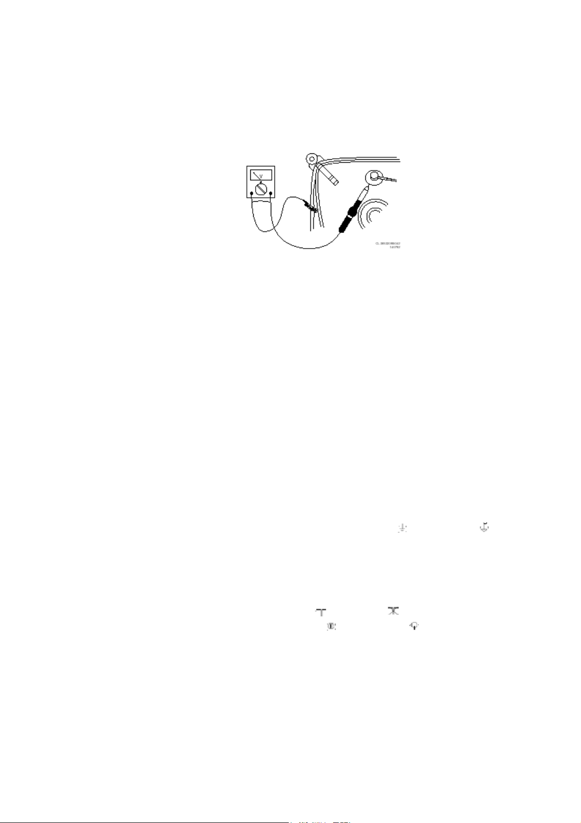
2.3 Warnings
• In order to prevent damage to ICs and transistors, avoid all high voltage flashovers. In order to prevent damage
to the picture tube, use the method shown in Fig. 2-1, to discharge the picture tube. Use a high voltage probe
and a multi-meter (position VDC). Discharge until the meter reading is 0 V (after approx. 30 s).
-
• All ICs and many other semiconductors are susceptible to electrostatic discharges (ESD)_ Careless handling
during repair can reduce life drastically. When repairing, make sure that you are connected with the same
potential as the mass of the set by a wristband with resistance. Keep components and tools also at this potential.
Available ESD protection equipment:
– Complete kit ESD3 (small tablemat, wristband, connection box, extension cable, and ground cable)
– Wristband tester 4822 344 13999.
• Together with the deflection unit and any multi-pole unit, flat square picture tubes form an integrated unit. The
deflection and the multi-pole units are set optimally at the factory. Adjustment of this unit during repair is
therefore not recommended.
• Be careful during measurements in the high voltage section and on the picture tube.
• Never replace modules or other components while the unit is switched ON.
• When you align the set, use plastic rather than metal tools. This will prevent any short circuits and the danger of
a circuit becoming unstable.
2.4 Notes
• Measure the voltages and waveforms with regard to the chassis (= tuner) ground (
), or hot ground ( ),
depending on the area of circuitry being tested.
• The voltages and waveforms shown in the diagrams are indicative. Measure them in the Service Default Mode
(see chapter 5) with a color bar signal and stereo sound (L: 3 kHz, R: 1 kHz unless stated otherwise) and picture
carrier at 475.25 MHz (PAL) or 61.25 MHz (NTSC, channel 3).
• Where necessary, measure the waveforms and voltages with (
voltages in the power supply section both in normal operation (
) and without ( ) aerial signal. Measure the
) and in standby ( ). These values are
indicated by means of the appropriate symbols.
• The picture tube panel has printed spark gaps. Each spark gap is connected between an electrode of the picture
tube and the Aquadag coating.
• The semiconductors indicated in the circuit diagram and in the parts lists are completely interchangeable per
position with the semiconductors in the unit, irrespective of the type indication on these semiconductors.
5--60
3. Directions for Use
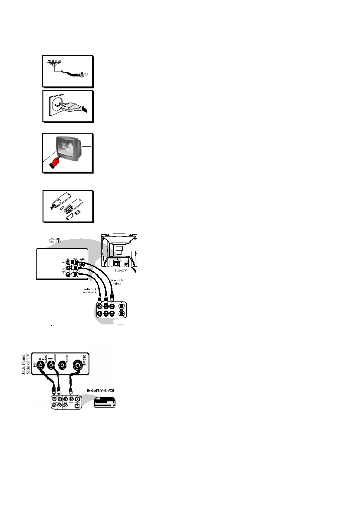
Antenna Connection • Connect the aerial plug to the antenna socket ¬on the back cover.
• Insert the mains plug into the wall socket.
Mains Connection• For correct mains voltage, refer to type sticker at the rear of the TV
set • Consult your dealer if mains supply is different.
Switching on the Set • Press the main power button to switch on/off the TV.
• If the set is on standby (indicator is red), press the Power button on the remote
control to switch on set.
Using the Remote Control • Insert the correct type of batteries into the compartment.
• Ensure the batteries are placed in the right direction.
CONNECTING THE AUDIO/VIDEO SOCKETS (PLAYBACK)
You can view the playback of VCR tapes (Video Disc players,
camcorders, etc.) by using the AUDIO and VIDEO INPUT
sockets on the rear of the TV.
-
Connect the VIDEO and AUDIO IN sockets on the rear of the
TV to the AUDIO and VIDEO OUT sockets on the VCR.
The S-Video connection on the rear of the TV is us
the playback of S-VHS VCR tapes, Video Discs,Vid
isc-Interactive (cd-i) discs. Better picture detail a
D nd clarity is possible with
the S-Video playback as compared to the picture fr
ection.
conn
nnect the S-VIDEO socket on the rear of the T HS OUT
– Co V to the S-V
socket on a S-VHS VCR.
- Connect the AUDIO IN sockets from the rear of t
OUT sockets on the VCR.
Note : You need not connect the VIDEO IN socket of the TV
if S-VIDEO IN so
cket is connected.
ed for
eo Games or Compact
om a normal antenna (RF)
he TV to the AUDIO
6--60
USING THE LANGUANGE CONTROL
7--60
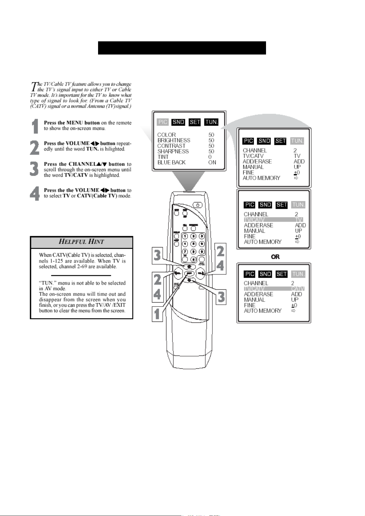
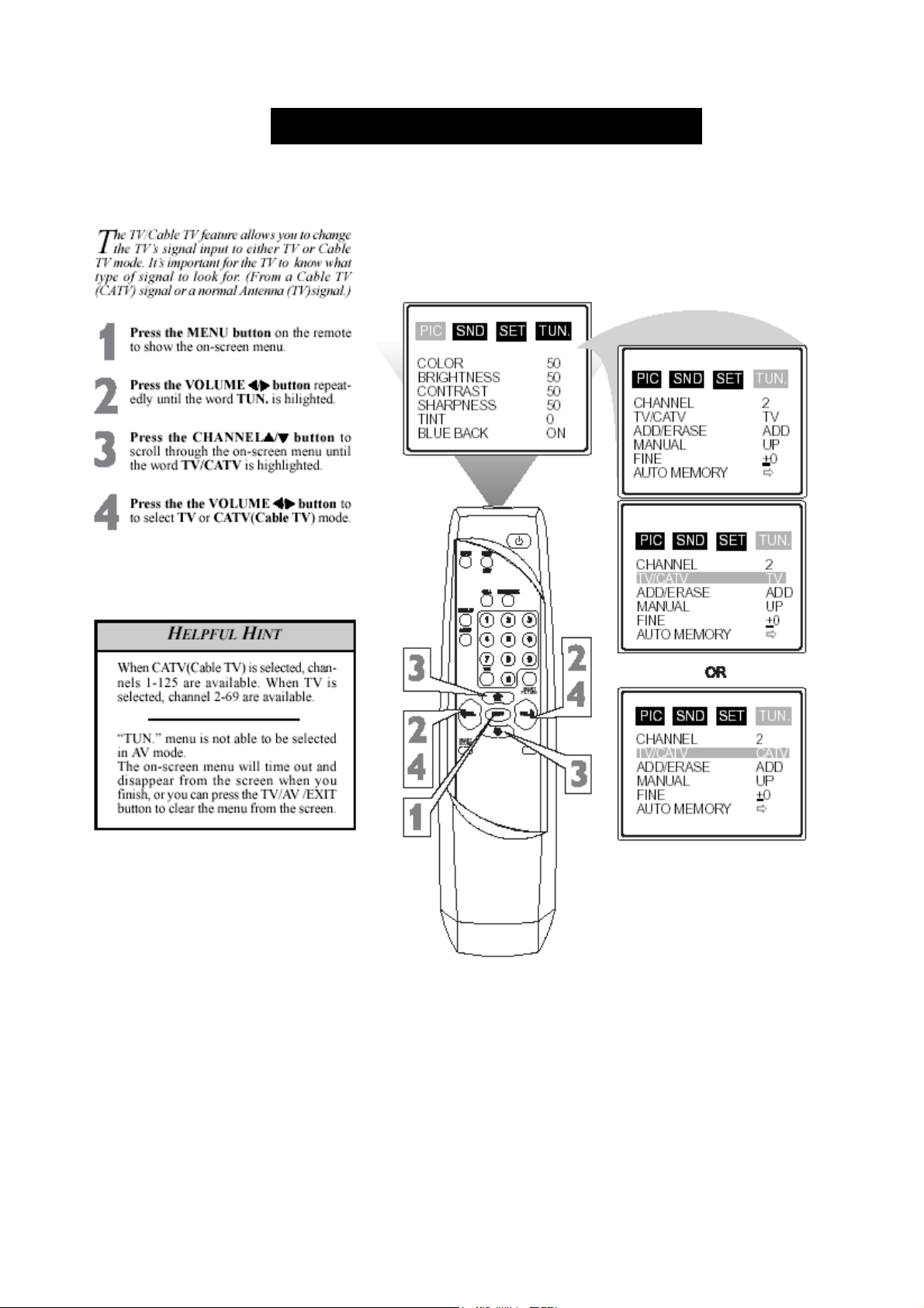
SETING THE TV/CABLE TV CONTROL
8--60
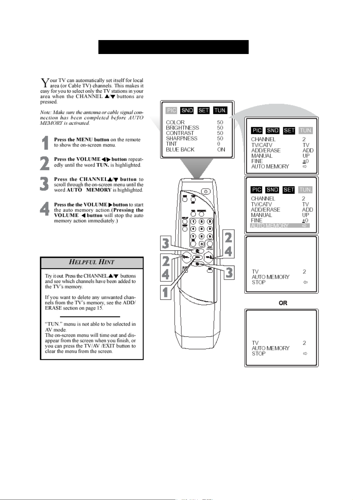
USING THE AUTO MEMORY CONTROL
9--60
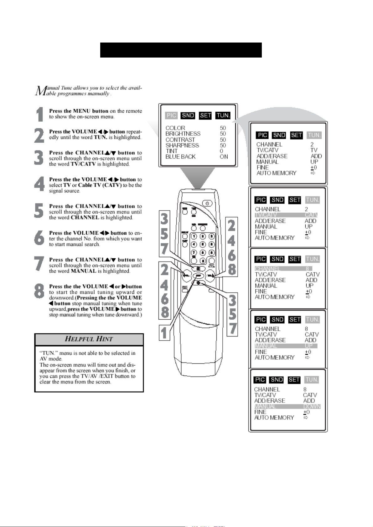
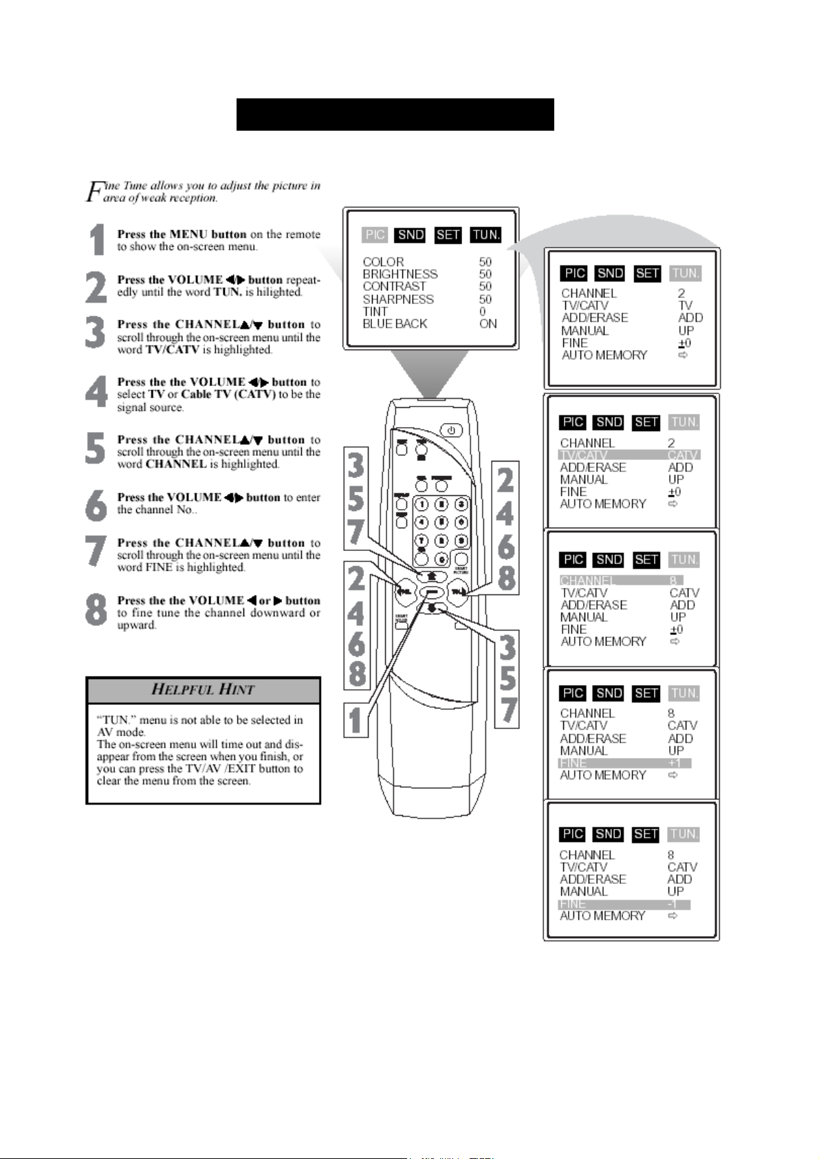
USING THE MAUNAL TUNE CONTROL
10--60
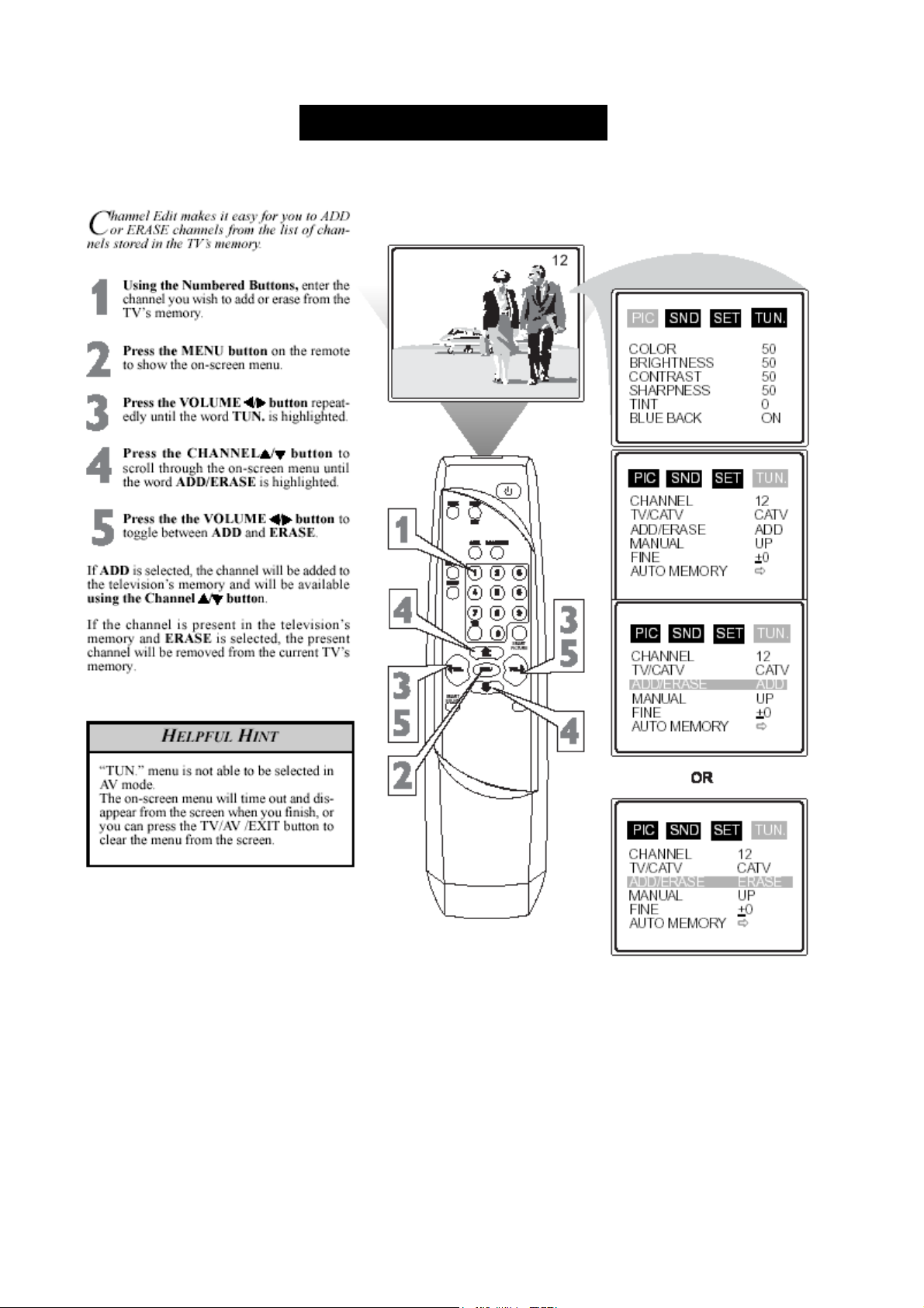
HOW TO ADD/ERASL CHANNELS
11--60
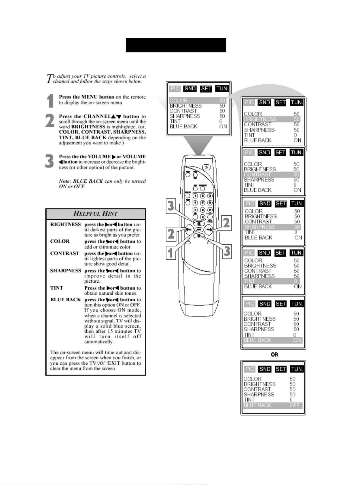
HOW TO ADJUST TV PICTURE
12--60
SMART PICTURE CONTROL
13--60
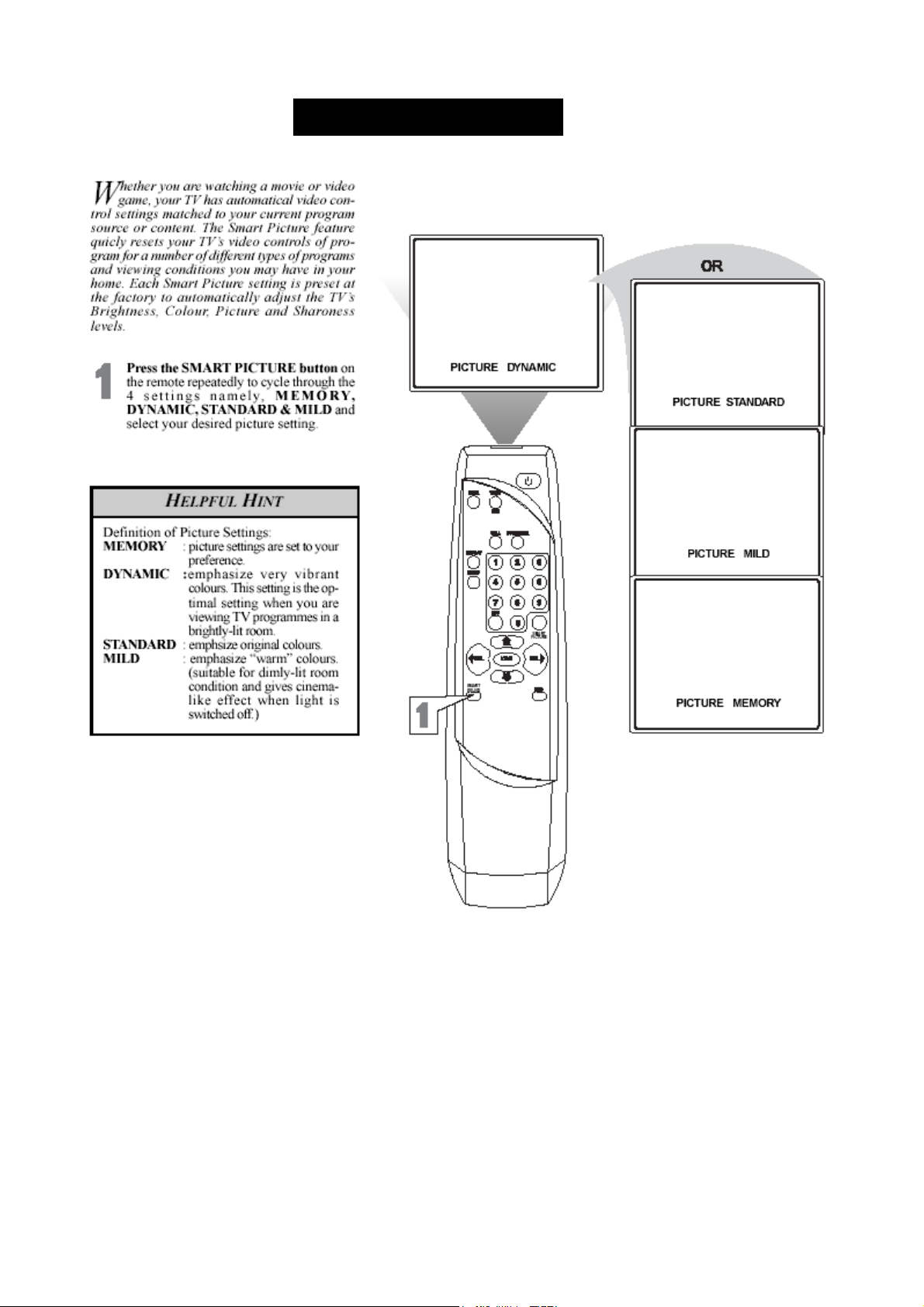
SMART PICTURE CONTROL
14--60
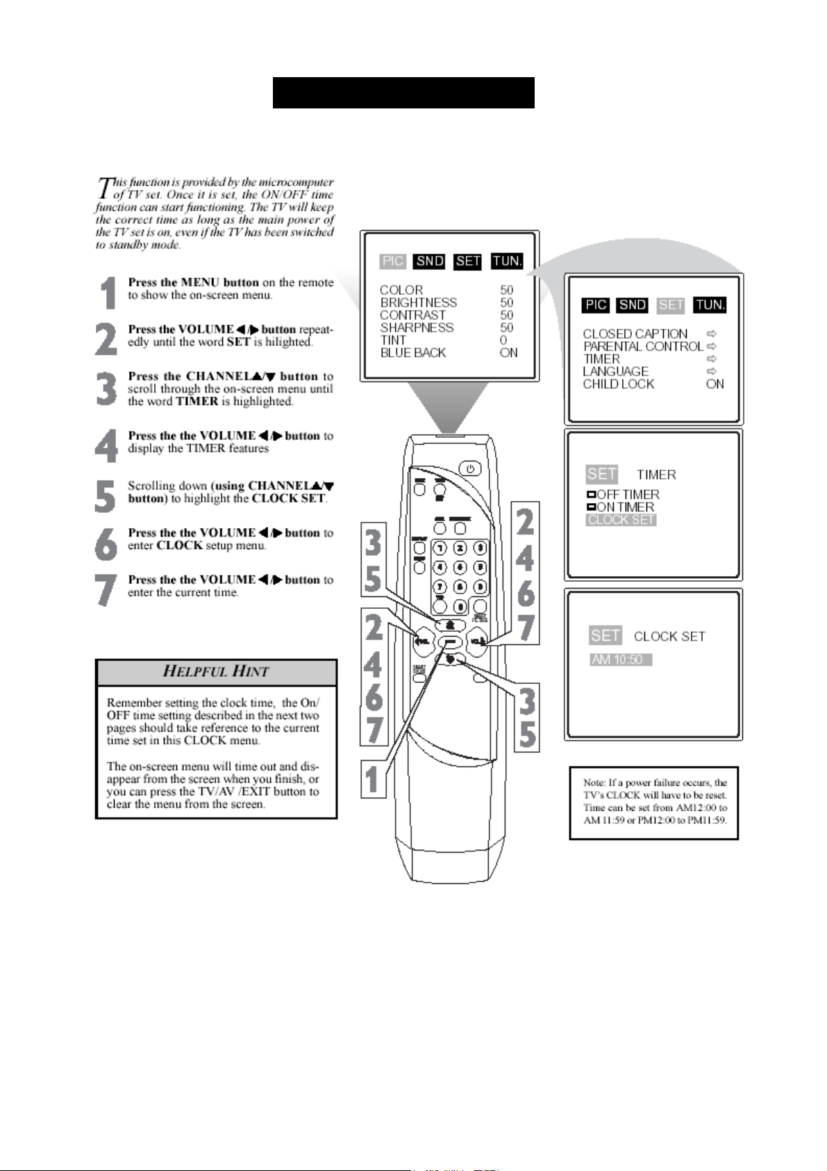
SETTING THE CLOCK FEATUREE
15--60
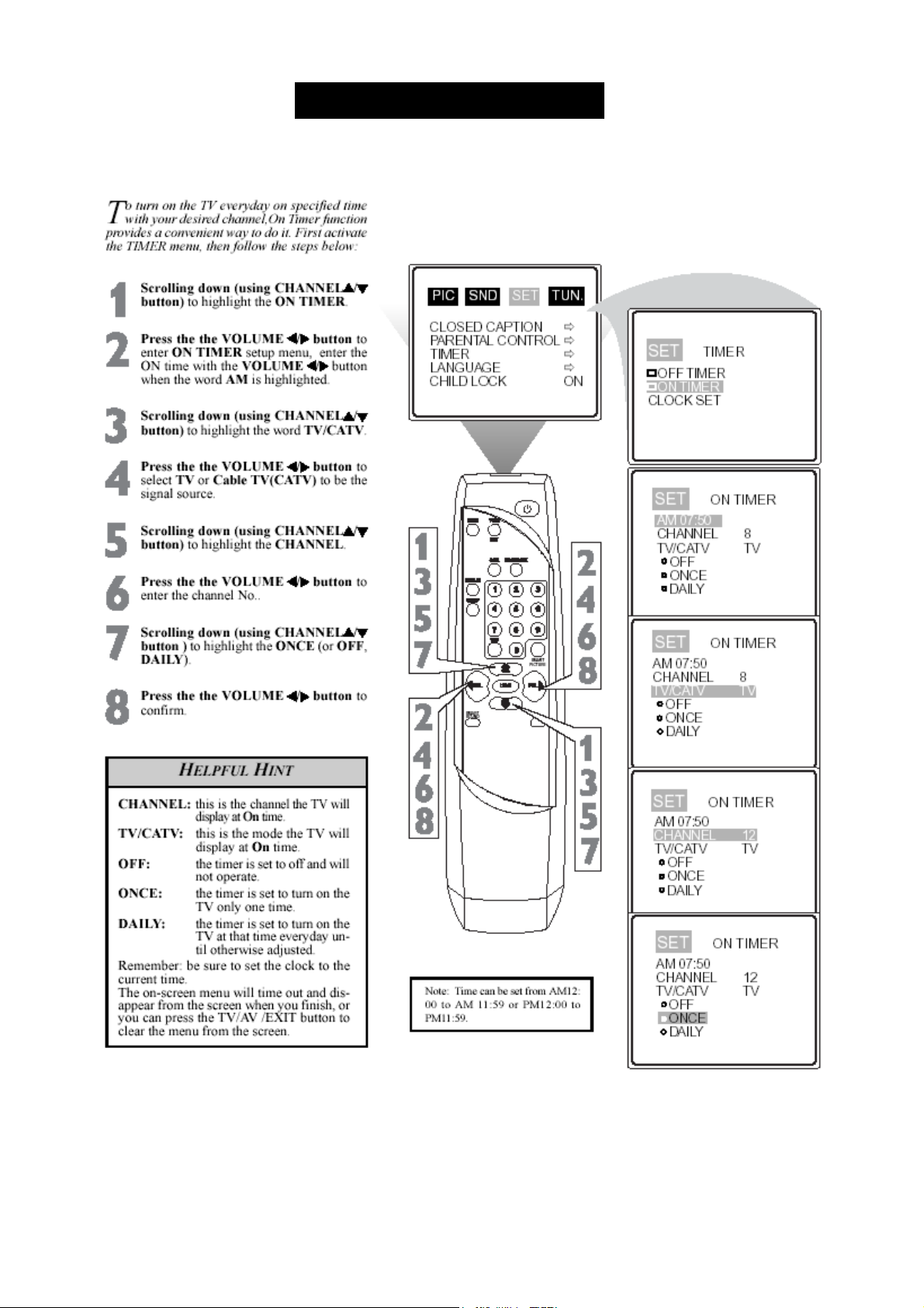
SETTING THE ON TIMER CONTROL
16--60
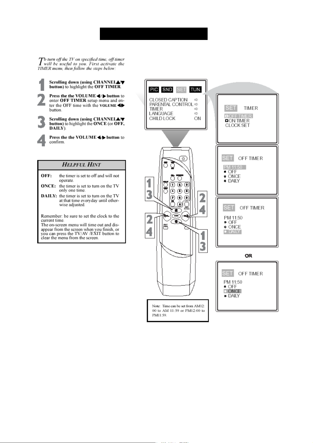
SETTING THE OFF TIME CONTROL
17--60
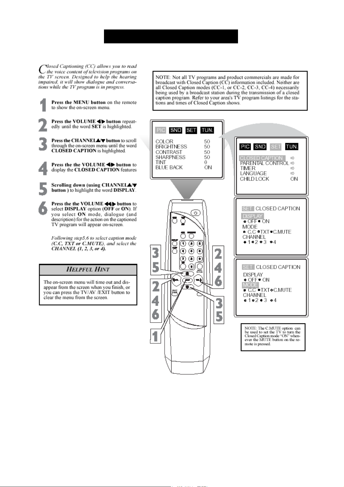
SETTING THE TV FOR CLOSED CAPTION
18--60
 Loading...