

Philips 273E3LHSB/00, 273E3LHSB/01, 273E3LHSB/27, 273E3LHSB/69, 273E3LHSB/73 Service Manual
...
27ƎLCD Color Monitor Chassis: Meridian 3
Service
Service
Service
Description
Page
Table of Contents.........................................………….1
Revision List………….................................................2
Important Safety Notice…………................................3
1. Monitor Specifications….........................................5
2. LCD Monitor Description….....................................7
3. Operation Instructions….........................................8
3.1General Instructions…………………………….…...8
3.2 Control Buttons…………..……………………….…8
3.3 OSD Menu………………….................................9
4. Input/output Specification............................……10
4.1 Input Signal Connector.................................……10
4.2 Resolution & Preset Modes.................................11
4.3 Pixel Defect Policy…………………………………12
4.4 Failure Mode of Panel………………………….....14
5. Block Diagram………………………….................15
5.1 Scaler Board....................................………….....15
5.2 Power Board.........................................…...........16
6. Schematic Diagram.............................................. 17
Description
Page
6.1 Scaler Board…………………….…………………17
6.2 Power Board.................................................…...23
6.3 Key Board…….……………………………………25
7. PCB Layout………………………………………...26
7.1 Scaler Board……………………………………..26
7.2 Power Board……………...………………………28
7.3 Key Board………...………………………………30
8. Wiring Diagram………………………………….…..31
9. Scaler Board Overview…………………………....32
10. Mechanical Instructions………………………....33
1 1. Repair Flow Chart…….……………………………35
12. ISP Instructions...…............................................39
13. DDC Instructions….............................................44
14. White Balance, Luminance Adjustment…...........57
15. Monitor Exploded View…....................................59
16. Recommended & Spare Parts List...….............60
17. Different Parts List……………………….……….62
18. General Product Specification……… …...……….63
SAFETY NOTICE
ANY PERSON ATTEMPTING TO SERVICE THIS CHASSIS MUST FAMILIARIZE HIMSELF WITH THE
CHASSIS AND BE AWARE OF THE NECESSARY SAFETY PRECAUTIONS TO BE USED WHE N
SERVICING ELECTRONIC EQUIPMENT CONTAINING HIGH VOLTAGES.
CAUTION: USE A SEPARATE ISOLATION TRANSFOMER FOR THIS UNIT WHEN SERVICING
REFER TO BACK COVER FOR IMPORTANT SAFETY GUIDELINES
Copyright 2011 Philips Consumer Lifestyle Subject to modification ƻK Mar.17, 2011
273E3LHSB/00
273E3LHSB/01
273E3LHSB/27
273E3LHSB/69
273E3LHSB/73
273E3LHSB/75
273E3LHSB/96

!
!
Meridian 3
2
Revision List
Version Release Date Revision History
A00 Mar.17,2011 Initial release, Draft Version
A01 Apr.06,2011 Update BOM for 273E3LHSB/75
A02 May.06,2011 Add CTN model 273E3LHSB/69
A03 May.11,2011 Add CTN models 273E3LHSB/27 and 273E3LHSB/96
A04 Oct.18,2011 Update BOM for 273E3LHSB/27
A05 Jun.4,2012 Add CTN model 273E3LHSB/01
A06 Jun.5,2012 Add CTN model 273E3LHSB/73

3
Meridian 3
Important Safety Notice
This electronic user guide is intended for anyone who uses the Philips monitor. Take time to read this user manual
before you use your monitor. It contains important information and notes regarding operating your monitor. The
Philips guarantee applies provided the product is handled properly for its intended use, in accordance with its
operating instructions and upon presentation of the o riginal invoice or cash receipt, indicatin g the date of p urchase,
dealers name and model and production number of the product.
Warnings
Use of controls, adjustments or procedures other than those specified in this document ation may result in exposure
to shock, electrical hazards and/or mechanical hazards. Read and follow these instructions when connecting and
using your computer monitor.
Operation
y Keep the monitor out of direct sunlight and away from stoves or any other heat source.
y Remove any object that could fall into ventilation holes or prevent proper cooling of the monitor’s electronics.
y Do not block the ventilation holes on the cabinet.
y When positioning the monitor , make sure the power plug and outlet are easily accessible.
y If turning off the monitor by detaching the power cable or DC power cord, wait for 6 seconds before attaching
the power cable or DC power cord for normal operation.
y Please use approved power cord provided by Philips all the time. If your power cord is missing, please contact
with your local service center. (Please refer to Customer Care Consumer Information Center)
y • Do not subject the monitor to severe vibration or high impact conditions during operation.
y • Do not knock or drop the monitor during operation or transportation.
Maintenance
y To protect your monitor from possible damage, do not put excessive pressure on the LCD panel. When moving
your monitor, grasp the frame to lift; do not lift the monitor by placing your hand or fingers on the LCD panel.
y Unplug the monitor if you are not going to use it for an extensive period of time.
y Unplug the monitor if you need to clean it with a slightly damp cloth. The screen may be wiped with a dry cloth
when the power is off. However , never use organic sol vent, such as, alcoh ol, or ammonia-ba sed liquids to clean
your monitor.
y To avoid the risk of shock or permanent damage to the set, do not expose the monitor to dust, rain, water, or
excessive moisture environment.
y If your monitor gets wet, wipe it with dry cloth as soon as possible.
y If foreign substance or water gets in your monitor, please turn the power off immediately and disconnect the
power cord. Then, remove the foreign substance or water, and send it to the maintenance center.
y Do not store or use the monitor in locations exposed to heat, direct sunlight or extreme cold.
y In order to maintain the best performance of your monitor and use it for a longer lifetime, please use the monitor
in a location that falls within the following temperature and humidity ranges.
¾ Temperature: 0-40°C 32-95°F
¾ Humidity: 20-80% RH

!
!
Meridian 3
4
y IMPORTANT: Always activate a moving screen saver program when you leave your monitor unattended.
Always activate a periodic screen refresh application if your monitor will display unchanging static content.
Uninterrupted display of still or static images over an extended period may cause “burn in”, also known a s
“after-imaging” or “ghost imaging”, on your screen. "Burn-in", "after-imaging", or "ghost imaging" is a
well-known phenomenon in LCD panel technology. In most cases, the “burned in” or “after-imaging” or “ghost
imaging” will disappear gradually over a period of time after the power has bee n switched off.
Warning
Severe” burn-in” or “after-image” or “ghost image” symptoms will not disappear and cannot be repaired. The
damage mentioned above is not covered under your warranty.
Service
y The casing cover should be opened only by qualified service personnel.
y If there is any need for any document for repair or integration, please contact with your local service center.
(Please refer to the chapter of "Consumer Information Center")
y For transportation information, please refer to "Technical Specifications".
y Do not leave your monitor in a car/trunk under direct sun light.
Note
Consult a service technician if the monitor does not operate normally, or you are not sure what procedure to take
when the operating instructions given in this manual have been followed.
5
Meridian 3
1. Monitor Specifications
Technical specifications
Picture/Display
LCD Panel Type TFT-LCD
Backlight WLED 273E3LH
Panel Size 27" (68.6 cm)
Aspect Ratio 16:9
Pixel Pitch 0.31 x 0.31 mm
Brightness 300 cd/m²
SmartContrast 20,000,000:1
Contrast Ratio (typ.) 1000:1
Response Time (typical) 2 ms
Optimum Resolution 1920 x 1080 @ 60Hz
Viewing Angle 170° (H) / 160° (V) @ C/R > 10
Picture Enhancement SmartImage Lite
Display Colors 16.7 M
Vertical Refresh Rate 56Hz - 76Hz
Horizontal Frequency 30 KHz - 83 KHz
sRGB YES
Connectivity
Signal Input DVI-D (Digital), VGA (Analog)
Input Signal Separate Sync, Sync on Green
Convenience
User Convenience
OSD Languages
English, French, German, Italian, Russian, Spanish, Simplified
Chinese, Portuguese, Turkish
Other convenience Kensington lock
Plug & Play Compatibility DDC/CI, sRGB, Windows 7, Mac OSX, Linux
Stand
Tilt -5 / +20
Power
On mode TBD W (typ.)
Energy Consumption
(EnergyStar 5.0 test method)
AC Input Voltage at
100V AC +/- 5V AC,
50Hz +/- 5Hz
AC Input Voltage at
115V AC +/- 5V AC,
50Hz +/- 5Hz
AC Input Voltage at
230V AC +/- 5V AC,
50Hz +/- 5Hz
Normal Operation (typ.) 20.43 W 20.35 W 20.40 W
Sleep 0.5 W 0.5 W 0.5 W
Off 0.3 W 0.3 W 0.3 W
!
!
Meridian 3
6
Heat Dissipation*
AC Input Voltage at
100V AC +/- 5V AC,
50Hz +/- 5Hz
AC Input Voltage at
115V AC +/- 5V AC,
50Hz +/- 5Hz
AC Input Voltage at
230V AC +/- 5V AC,
50Hz +/- 5Hz
Normal Operation 69.73 BTU/hr 69.45 BTU/hr 69.62 BTU/hr
Sleep 1.71 BTU/hr 1.71 BTU/hr 1.71 BTU/hr
Off 1.02 BTU/hr 1.02 BTU/hr 1.02 BTU/hr
Power LED indicator On mode: White, Standby/Sleep: White (Blinking)
Power Supply Burn-in, 100~240VAC, 50-60Hz
Dimension
Product with Stand (W x H x D) 642 x 440 x 227 mm
Product without Stand (W x H x
D)
642 x 391 x 64 mm
Box Dimension (W x H x D) 700 x 138 x 525 mm
Weight
Product with Stand 8.2 kg
Product without Stand 6.5 kg
Product with Packaging 8.82 kg
Operating Condition
Temperature Range (operation) 0°C to 40 °C
Temperature Range (storage) -20°C to 60°C
Relative Humidity 20% to 80%
Altitude
operation: +120,000 ft (3,658 m)
Non-operation: + 40,000ft (12,192 m)
MTBF 50,000hrs
Environmental
ROHS YES
EPEAT Silver. (www.epeat.net)
Packaging 100% recyclable
Specific Substances
PVC/BFR Free
3
for User Accessible Parts (Excluding Cables and
Adaptors)
Compliance and standards
Regulatory Approvals
CE Mark, FCC Class B, SEMKO, TÜV/ GS, TÜV Ergo, UL/cUL,
Energy star 5.0, TCO 5.1
Cabinet
Color Black / Black
Finish Texture / Texture
7
Meridian 3
Note:
1. EPEAT Gold or Silver is valid only where Philips registers the product. Please visit www.epeat.net
for
registration status in your country.
2. This data is subject to change without notice. Go to www.philips.com/support
to download the latest
version of leaflet.
3. This monitor is brominates flame retardant and polyvinyl chloride-free (PVC/BFR free) for all user
accessible parts (excluding cables and adaptors). Organ bromine compounds in the form of flame
retardants must not be used in those portions equal to or greater than 0.09% (900ppm maximum of
Bromine) and organ bromine compounds in the form of polyvinyl chloride or polyvinyl chloride congeners
must not be used in those portions equal to or greater than 0.1% (1000ppm maximum of chlorine).
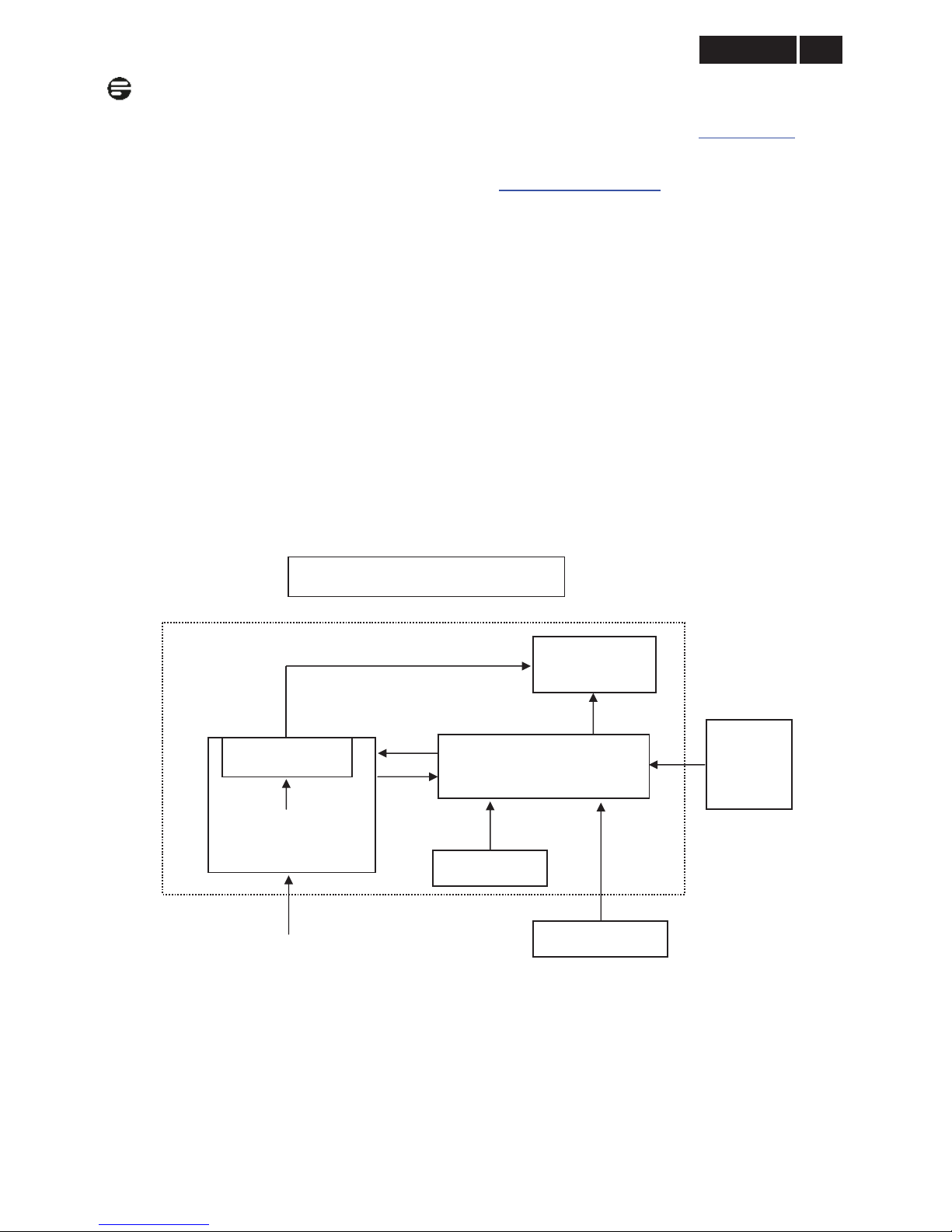
2. LCD Monitor Description
The LCD monitor will contain a scaler board, a power board and a key board. The scaler board houses the flat
panel control logic, brightness control logic and DDC.
The power board will provide AC to DC inverter voltage to drive the backlight of panel and the scaler board chips
each voltage.
Adapter Board
Monitor Block Diagram
DC 14.5V
Converter Board
LED Panel
Scaler Board
(Include: Audio)
HDMI
DVI-D
D-SUB
LED Drive
Video signal, DDC
Key Board
HOST Computer
AC IN
90 ~ 264 V
!
!
Meridian 3
8
3. Operating Instructions
3.1 General Instructions
Press the power button to turn the monitor on or off.
The other control knobs are located at front panel of
the monitor. By changing these setting, the picture
can be adjusted to your personal preference.
γThe power cord should be connected.
γ Press the power button to turn on the monitor.
The power indicator will light up.
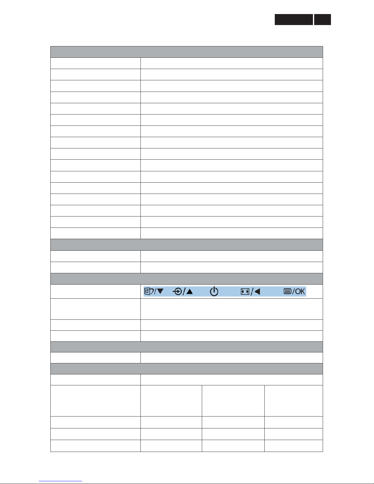
3.2 Control Buttons
Operating the Monitor
Front view product description
1.
: To access the OSD menu.
2.
: Return to previous OSD level.
4.
: To switch monitor’s power on and off.
5.
: To adjust the OSD menu.
6.
: To change the signal input source.
7.
: SmartImage Lite: there are three modes to be
selected: Standard, Internet and Game.
8.
: To adjust volume of the display
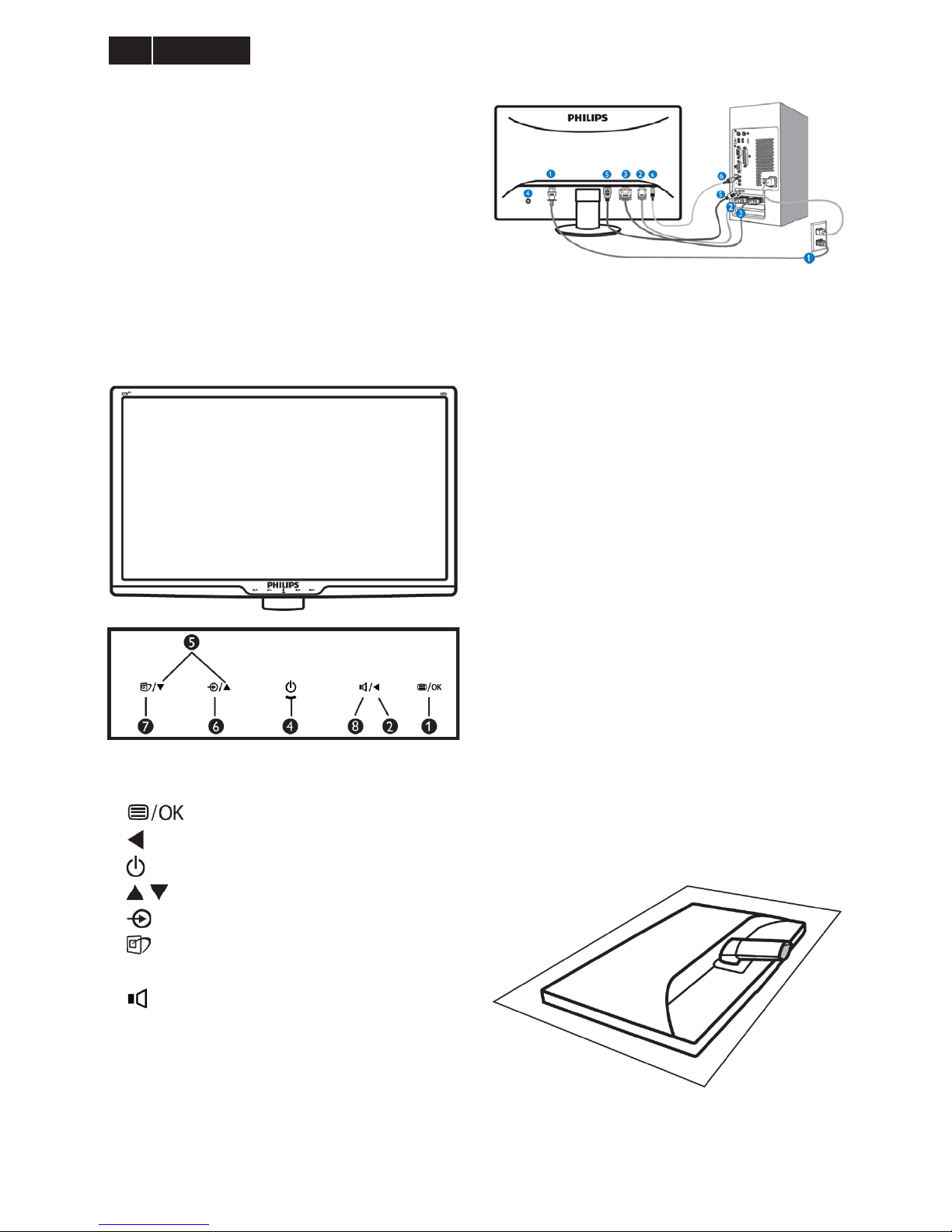
Connecting to your PC
1. AC power input
2. VGA input
3. DVI-D input
4. Kensington anti-thief lock
5. HDMI input
6. Audio input
Connect to PC
1. Connect the power cord to the back of the monitor
firmly.
2. Turn off your computer and unplug its power
cable.
3. Connect the monitor signal cable to the video
connector on the back of your computer.
4. Plug the power cord of your computer and your
monitor into a nearby outlet.
5. Turn on your computer and monitor. If the monitor
displays an image, installation is complete.
Install base stand
1. Place the monitor face down on soft smooth
surface taking care to avoid scratching or
damaging the screen.
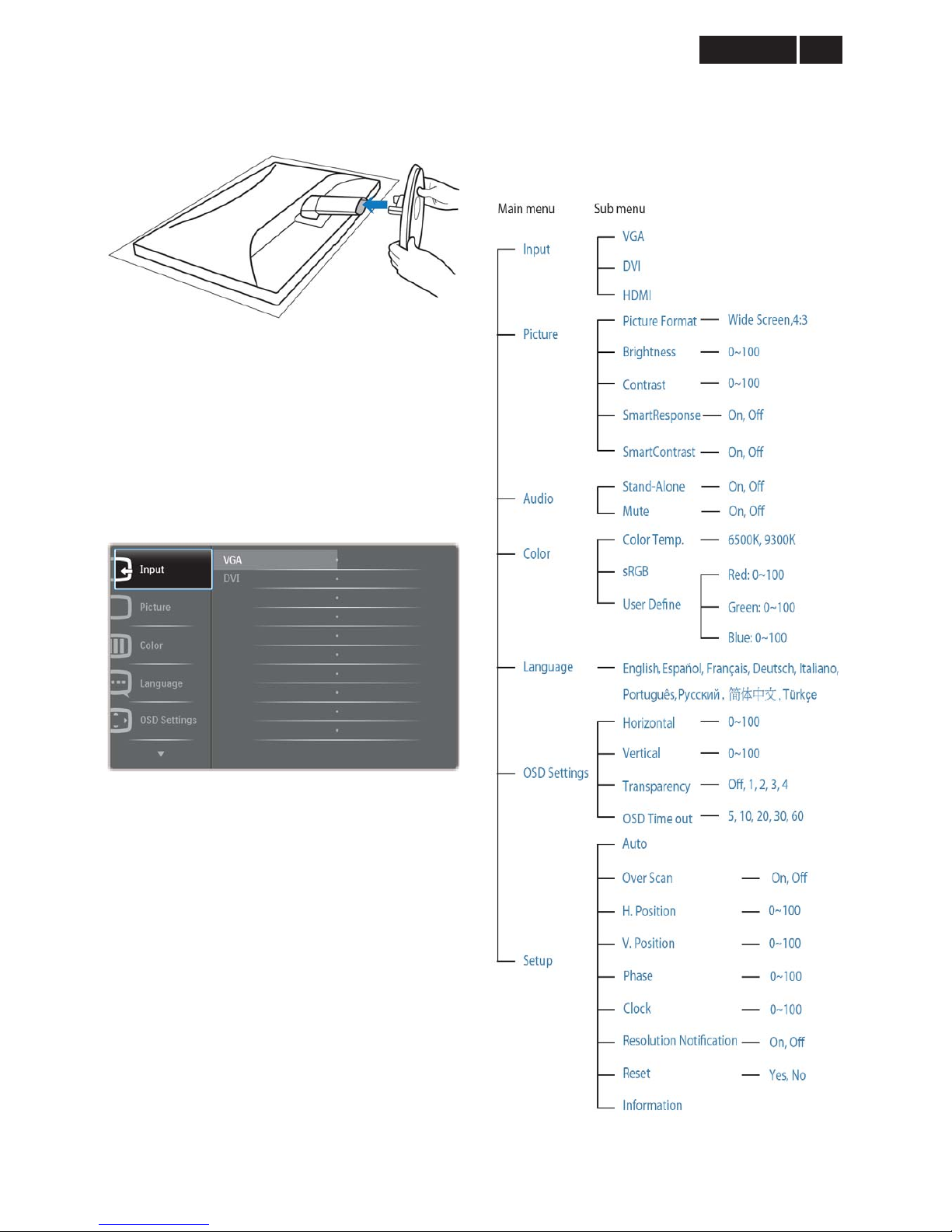
9
Meridian 3
2. Hold the monitor base stand with both hands
and firmly insert the base stand into the base
column.
3.3 OSD Menu
On-screen Display (OSD) is feature in all Philips LCD
monitors. It allows an end user to adjust screen
performance or select functions of the monitors directly
through an on-screen display inter face is shown as
below:
Basic and simple instruction on the control keys
In the OSD shown above users can press źŸ buttons
at the front bezel of the monitor to move the cursor, OK
to confirm the choice or change.
To Lock/Unlock OSD function (User Mode)
The OSD function can be locked by pressing “MENU”
button for more than 6 seconds.
Locked OSD function can be released by pressing
“MENU” button for more than 6 seconds again.
The OSD tree
Below is an overall view of the structure of the
On-Screen Display. You can use this as a reference
when you want to work your way around the different
adjustments later on.
!
!
Meridian 3
10
4. Input/ Output Specification
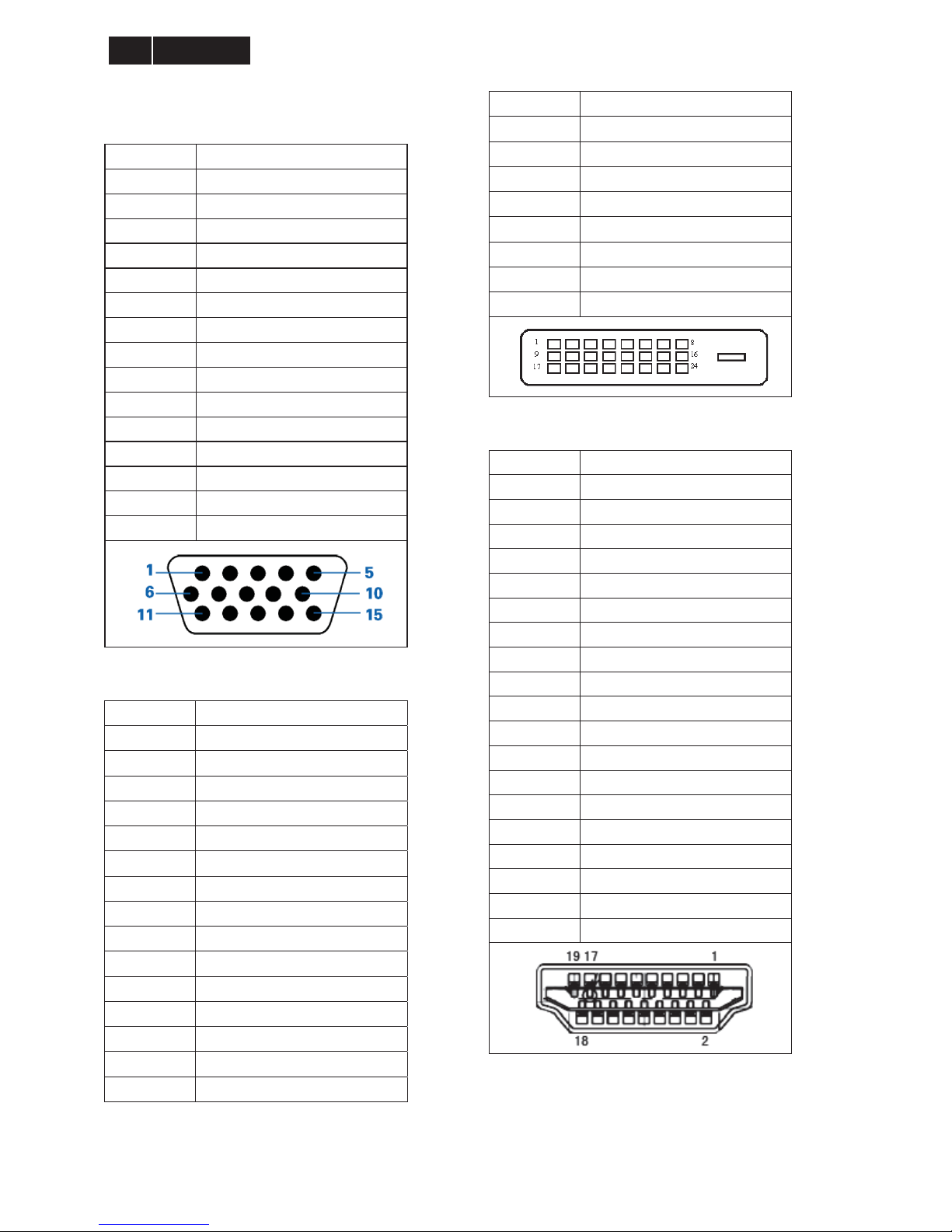
4.1 Input Signal Connector
D-sub Connector
Pin No. Signal Name
1 Red
2 Green/ SOG
3 Blue
4 Sense (GND)
5 Cable Detect (GND)
6 Red GND
7 Green GND
8 Blue GND
9 DDC +3.3V or +5V
10 Logic GND
11 Sense (GND)
12 Bi-directional data
13 H/H+V sync
14 V-sync
15 Data clock
DVI Connector
Pin No. Signal Name
1 T.M.D.S. data22 T.M.D.S. data2+
3 T.M.D.S. data2 shield
4 No Connect
5 No Connect
6 DDC clock
7 DDC data
8 No Connect
9 T.M.D.S. data110 T.M.D.S. data1+
1 1 T.M.D.S. data1 shield
12 No Connect
13 No Connect
14 +5V Power
15 Ground (for +5V)
16 Hot plug detect
17 T.M.D.S. data018 T.M.D.S. data0+
19 T.M.D.S. data0 shield
20 No Connect
21 No Connect
22 T.M.D.S clock shield
23 T.M.D.S. clock+
24 T.M.D.S. clock-
HDMI Connector
Pin No. Signal Name
1 TMDS data 2+
2 TMDS data 2 Shield
3 TMDS data 24 TMDS data 1+
5 TMDS data 1 Shield
6 TMDS data 17 TMDS data 0+
8 TMDS data 0 Shield
9 TMDS data 010 TMDS data ck+
1 1 TMDS data c Shield
12 TMDS data ck13 CEC
14 N.C
15 DDC SCL
16 DDC CLK
17 DDC/CEC Ground
18 +5 V Power
19 Hot Plug Detect
11
Meridian 3
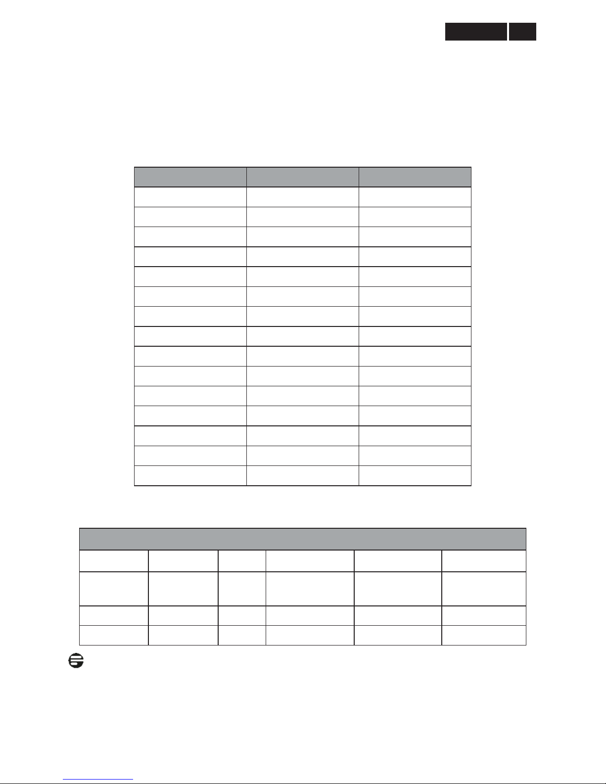
4.2 Resolution & Preset Modes
Maximum Resolution
1920 x 1080 at 60 Hz (analog input)
1920 x 1080 at 60 Hz (digital input)
Recommended Resolution
1920 x 1080 at 60 Hz (digital input)
H. freq (kHz) Resolution V. freq (Hz)
31.47 720 x 400 70.09
31.47 640 x 480 59.94
35.00 640 x 480 66.67
37.86 640 x 480 72.81
37.50 640 x 480 75.00
37.88 800 x 600 60.32
46.88 800 x 600 75.00
48.36 1024 x 768 60.00
60.02 1024 x 768 75.03
63.89 1280 x 1024 60.02
79.98 1280 x 1024 75.03
55.94 1440 x 900 59.89
70.64 1440 x 900 74.98
65.29 1680 x 1050 59.95
67.50 1920 x 1080 60.00
Power Management Definition
Power Management Definition
VESA Mode Video H-Sync V-Sync Power Used LED Color
Active ON Yes Yes
< 27.3 W (typ.)
< 32.3 W (max.)
White
Sleep OFF No NO < 0.5 W White (Blink)
Switch off OFF - - < 0.3 W OFF
Note:
This data is subject to change without notice.
!
!
Meridian 3
12
4.3 Pixel Defect Policy
Philips strives to deliver the highest quality products.
We use some of the industry’s most advanced
manufacturing process and practice stringent quality
control. However, pixel or sub pixel defects on the TFT
LCD panels used in flat panel monitors are sometimes
unavoidable. No manufacturer can guarantee that
panels will be free from pixel defects, but Philips
guarantees that any monitor with an unacceptable
number of defects will be repaired or replaced under
warranty. This notice explains the different types of
pixel defects and defines acceptable defect levels for
each type. In order to qualify for repair or replacement
under warranty, the number of pixel defects on a TFT
LCD panel must exceed these acceptable levels. For
example, no more than 0.0004% of the sub pixels on a
21.5Ǝ XGA monitor may be defective. Furthermore,
Philips sets even higher quality standard for certain
types or combinations of pixel defects that are more
noticeable than others. This policy is valid worldwide.
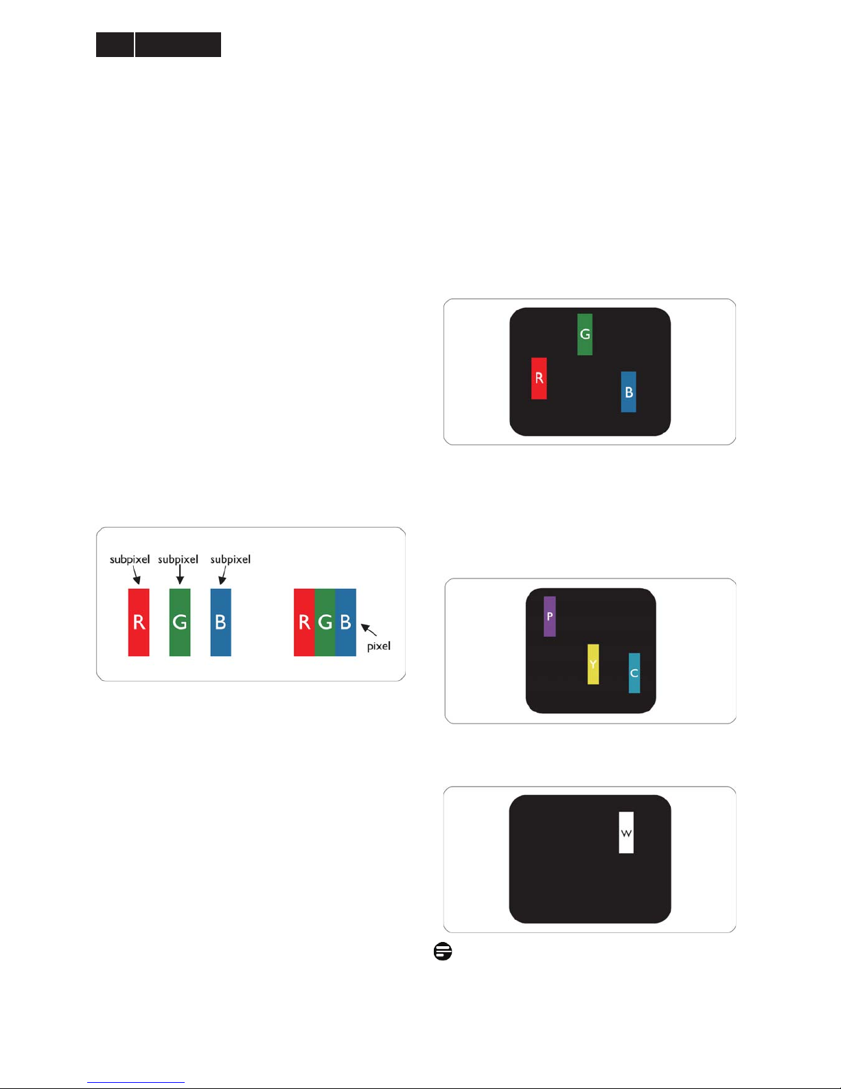
Pixels and Sub pixels
A pixel, or picture element, is composed of three sub
pixels in the primary colors of red, green and blue.
Many pixels together form an image. When all sub
pixels of pixel are lit, the three colored sub pixels
together appear as a single white pixel. When all are
dark, the three colored sub pixels together appear as a
signal black pixel. Other combinations of lit and dark
sub appear as single pixels of other colors.
Types of Pixel Defects
Pixel and sub pixel defects appear on the screen in
different ways. There are two categories of pixel
defects and several types of sub pixel defects within
each category.
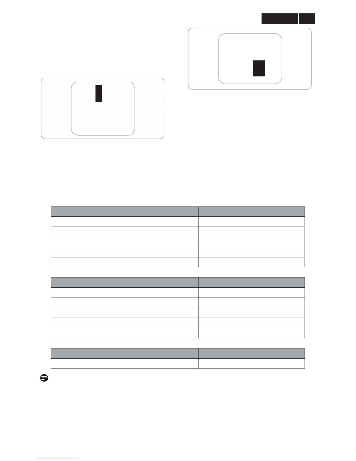
Bright Dot Defects Bright dot defects appear as pixel s
or sub pixels that are always lit or ‘on’. That is, a Bright
dot is a sub-pixel that stands out on the screen when
the monitor displays a dark pattern. There are three
types of bright dot defects:
One lit red, green or blue sub pixel
Two adjacent lit sub pixels:
- Red + Blue = Purple
- Red + Green = Yellow
- Green + Blue = Cyan (Light Blue)
Three adjacent lit sub pixels (one white pixel)
Note:
A red or blue bright dot must be more than 50 percent
brighter than neighboring dots while a green bright dot
is 30 percent brighter than neighboring dots.
13
Meridian 3
Black Dot Defects Black dot defects appear as pixels
or sub pixels that are always dark or ‘off’. That is, a
dark dot is a sub-pixel that stands out on the screen
when the monitor displays a light pattern. There are
two types of black dot defects:
Proximity of Pixel Defects
Because pixel and sub pixels defects of the same type
that are near to one another may be more noticeable,
Philips also specifies tolerances for the proximity of
pixel defects.
Pixel Defect Tolerances
In order to qualify for repair or replacement due to pixel
defects during the warranty period, a TFT LCD p anel in
a Philips flat panel monitor must have pixel or sub pixel
defects exceeding the tolerances listed in the followin g
tables.
Bright Dot Defects Acceptable level
1 lit subpixel 3
2 adjacent lit subpixels 1
3 adjacent lit subpixels (one white pixel) 0
Distance between two bright dot defects* >15mm
Total bright dot defects of all types 3
Black Dot Defects Acceptable level
1 dark subpixel 5 or fewer
2 adjacent dark subpixels 2 or fewer
3 adjacent dark subpixels 0
Distance between two black dot defects* >15mm
Total black dot defects of all types 5 or fewer
Total Dot Defects Acceptable level
Total bright or black dot defects of all types 5 or fewer
Note: 1. 1 or 2 adjacent sub pixel defects = 1 dot defect.
2. This monitor is ISO9241-307 compliant. (ISO9241-307: Ergonomic re quirement, analysis and
compliance test methods for electronic visual displays)
!
!
Meridian 3
14
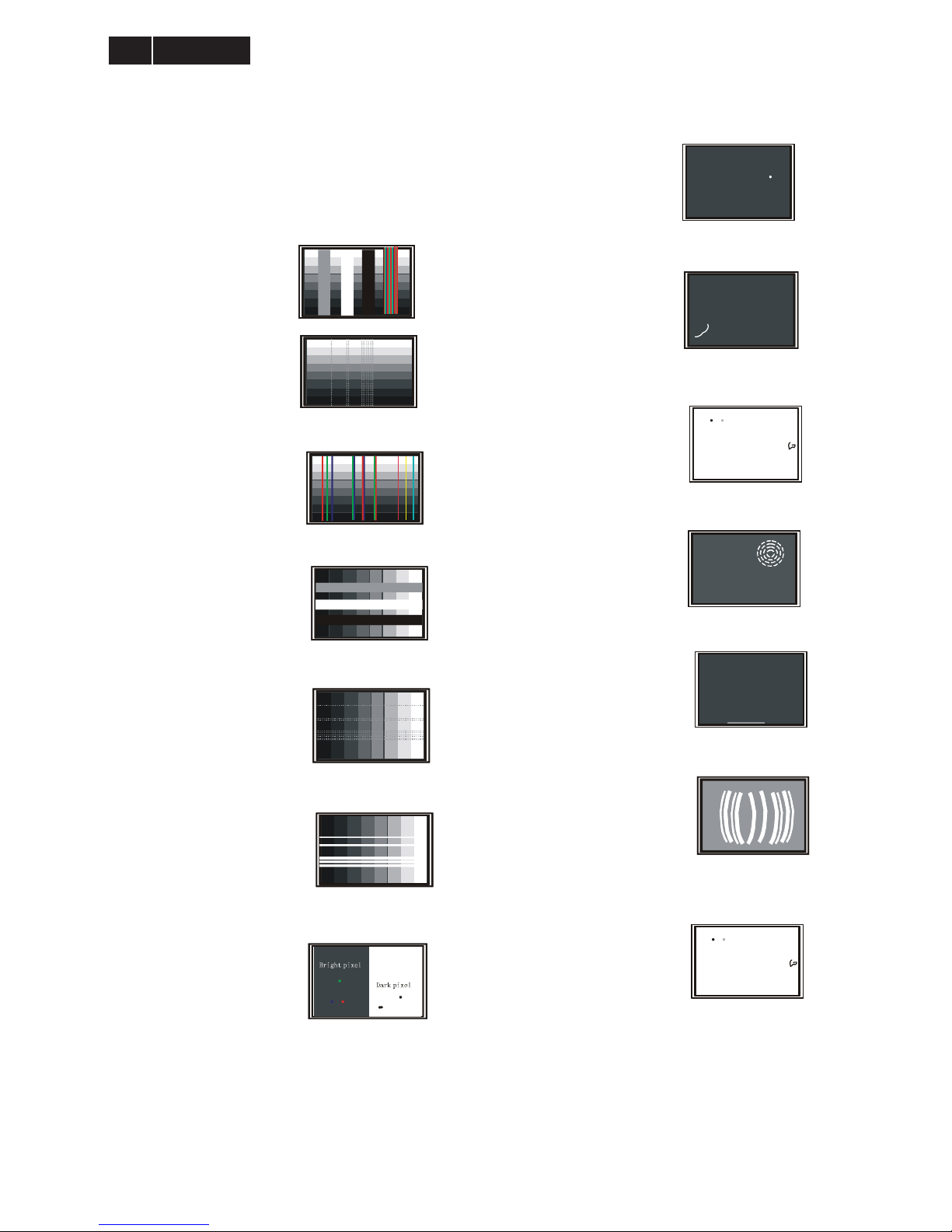
4.4 Failure Mode Of Panel
Failure description
Phenomenon
Vertical block defect
Vertical dim lines
Vertical lines defect
(Always bri
g
ht or dark)
Horizontal block de fect
Horizontal dim lines
Horizontal lines defect
(Always bri
g
ht or dark)
Has bri
g
ht or dark pixel
Polarizer has bubbles
Polarizer has bubbles
Foreign material inside
polarizer. It shows liner or
dot shape.
Concentric circle formed
Bottom back light of LCD is
brighter than normal
Back light un-uniformity
Backli
g
ht has foreign material.
Black or white color, liner or
circular type
Quick reference for failure mode of LCD panel
this pa
g
e presents problems that could be made by LCD panel.
It is not necessary to repair circuit board. Simply follow the mechanical
instruction on this manual to eliminate failure by replace LCD panel.
15
Meridian 3
5. Block Diagram
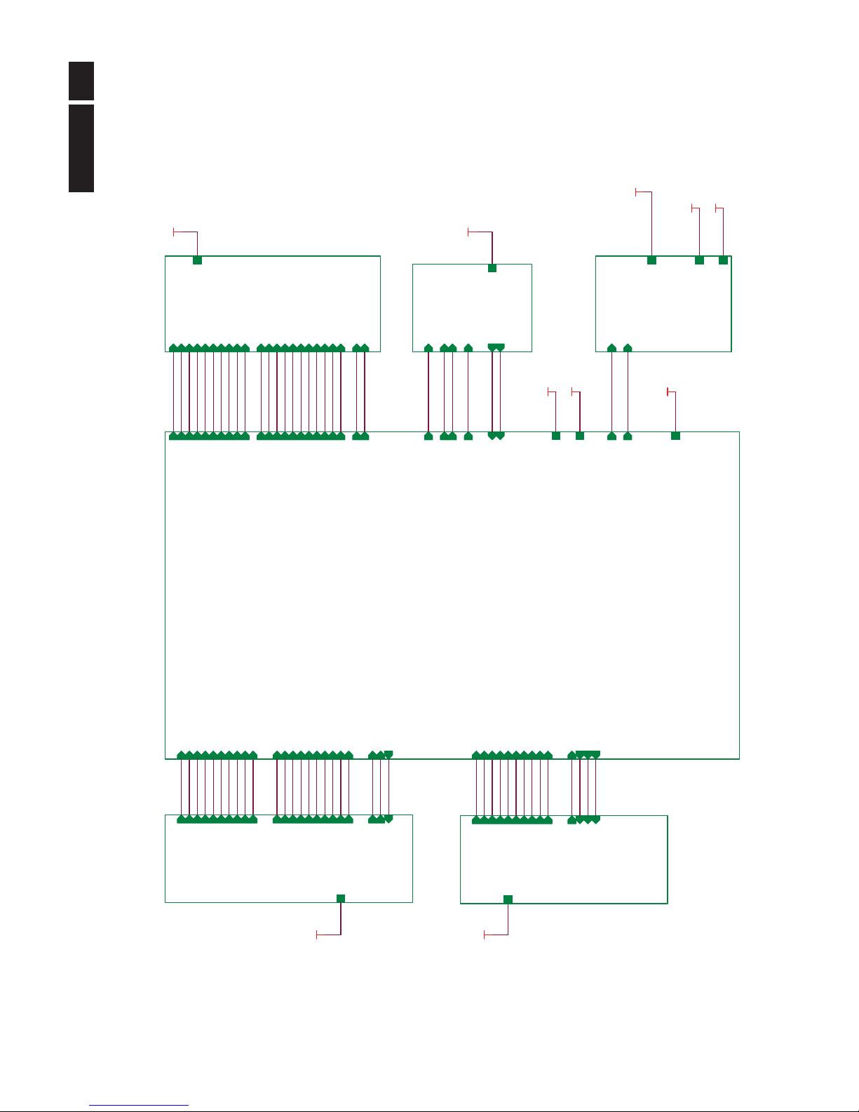
5.1 Scaler Board
+5V_SB
+5V_SB
02.INPUT
2.INPUT
RIN
GNDR
GIN
GNDG
BIN
GNDB
HSYNC
VSYNC
DDCA_SDA
DDCA_SCL
RX0+
RX0-
RX1-
RX1+
RX2+
RX2-
RXC-
RXC+
DVI_SDA
DVI_SCL
DET_VGAI
DET_DVII
DDC_WP
+5V_SB
VCC3.3
+5V_SB
+5V_SB
VCC1.8
04.SCALER
4.SCALER
RIN
GNDR
GIN
GNDG
BIN
GNDB
HSYNC
VSYNC
DDCA_SDA
DDCA_SCL
DVI_SCL
DVI_SDA
RX0+
RX0-
RX1+
RX1-
RX2+
RX2-
RXC+
RXC-
DET_VGAI
DET_DVII
DDC_WP
HDMI1_D2+
HDMI1_D2-
HDMI1_D1+
HDMI1_D1-
HDMI1_D0+
HDMI1_CK+
HDMI1_CK-
HDMI1_D0-
HDMI1_SDA
HDMI1_SCL
DET_HDMI
CEC_CTRL
HDMI_HPD
DDC_WP
Mute
AOUT_L
AOUT_R
on_Panel
on_BACKLIGHT
Adj_BACKLIGHT
VCC3.3
VCC1.8
PB0
PB1
PB2
PB3
PB4
PB5
PB6
PB7
PB8
PB9
PA0
PA1
PA2
PA3
PA4
PA5
PA6
PA7
PA8
PA9
+5V_SB
SCL_Panel
SDA_Panel
Volume
AIN_L
AIN_R
+5V_SB
+5V_SB
05.PANEL INTERFACE
5.PAN EL I NTERF AC E
+5V_SB
PA0
PA1
PA2
PA3
PA4
PA5
PA6
PA7
PA8
PA9
PB0
PB1
PB2
PB3
PB4
PB5
PB6
PB7
PB8
PB9
on_Panel
SCL_Panel
SDA_Panel
03.HDMI
3.HDMI
HDMI1_D2+
HDMI1_D2-
HDMI1_D1+
HDMI1_D1-
HDMI1_D0+
HDMI1_D0-
HDMI1_CK+
HDMI1_CK-
HDMI1_SDA
HDMI1_SCL
DET_HDMI
CEC_CTRL
HDMI_HPD
DDC_WP
+5V_SB
07.POWER
7.POWER
Adj_BACKLIGHT
on_BACKLIGHT
VCC1.8
VCC3.3
+5V_SB
VCC3.3
06.AUDIO
6.AUDIO
Mute
AOUT_L
AOUT_R
+5V_SB
Volume
AIN_R
AIN_L
VCC1.8
!
!
Meridian 3
16
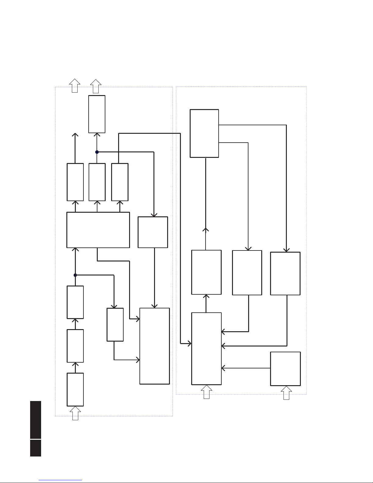
5.2 Power Board
PWM Control Circuit
(LED driver IC MP3389EF)
Feedback Control
Circuit
Switching Circuit
( PWM Control IC
& MOSFET )
Output (+16V) To
USB(Option) Circuit
Dimming Control Signal
(Burst model Signal )
Diode Rectifier
and Filter Circuit
Driver Circuit
( Full Bridge )
Input AC Source
85v / 60 Hz ~
264v / 50 Hz
Fuse For OLP
Converter Block Circuit
Diode Rectifier
and Filter Circuit
Rectification
Feedback
Control
Circuit
Abnormal Protect
Control Circuit
Main
Transformer
ON / OFF Control Signal
( 14.5v: on / 0v:off )
Rectification
Inrush
Prevention
Output (+5V) To Main
board /Audio *2W
EMI Filter
Circuit
Adapter Block Circuit
Dimming
Control
Circuit
B+
Diode Rectifier
and Filter Circuit
LED panel
17
Meridian 3
6. Schematic
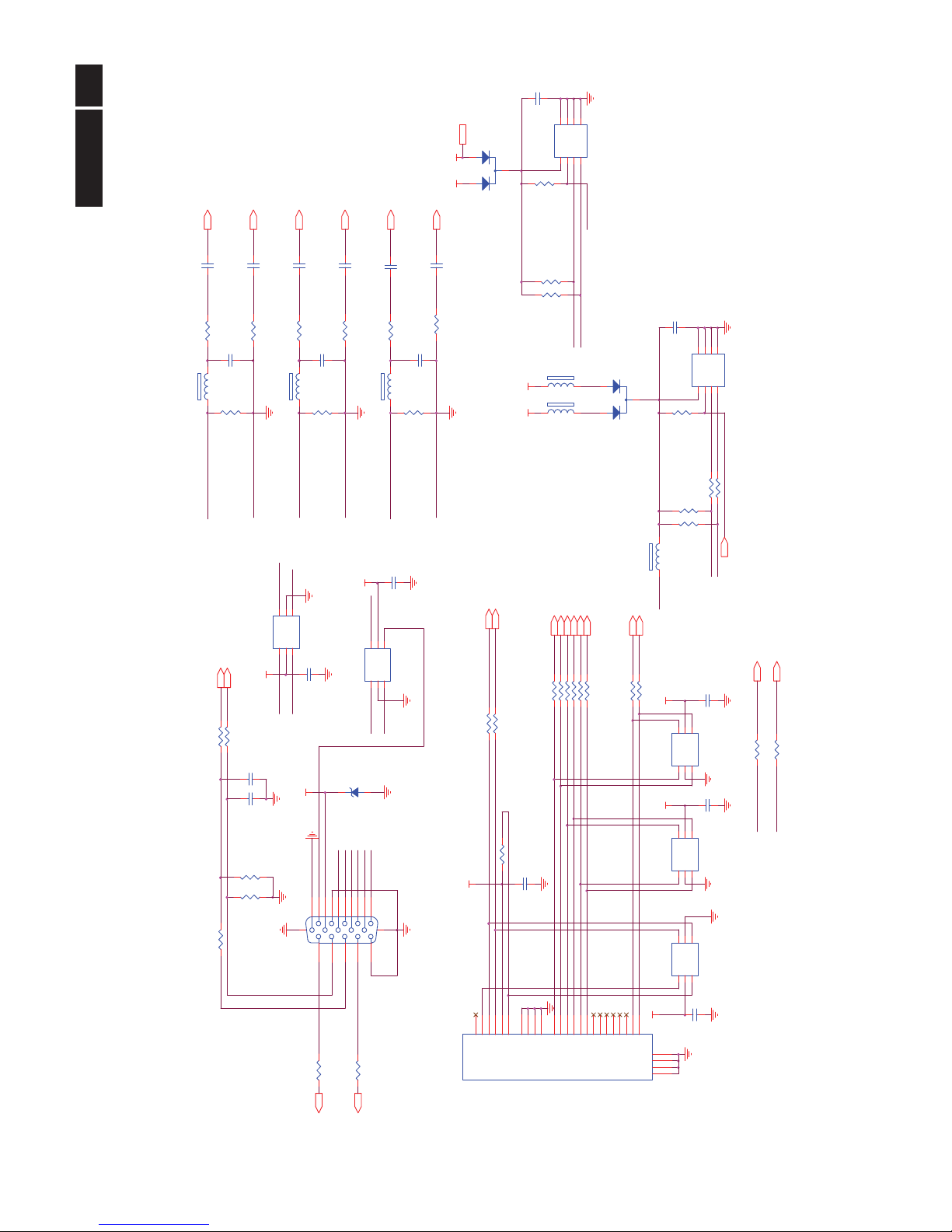
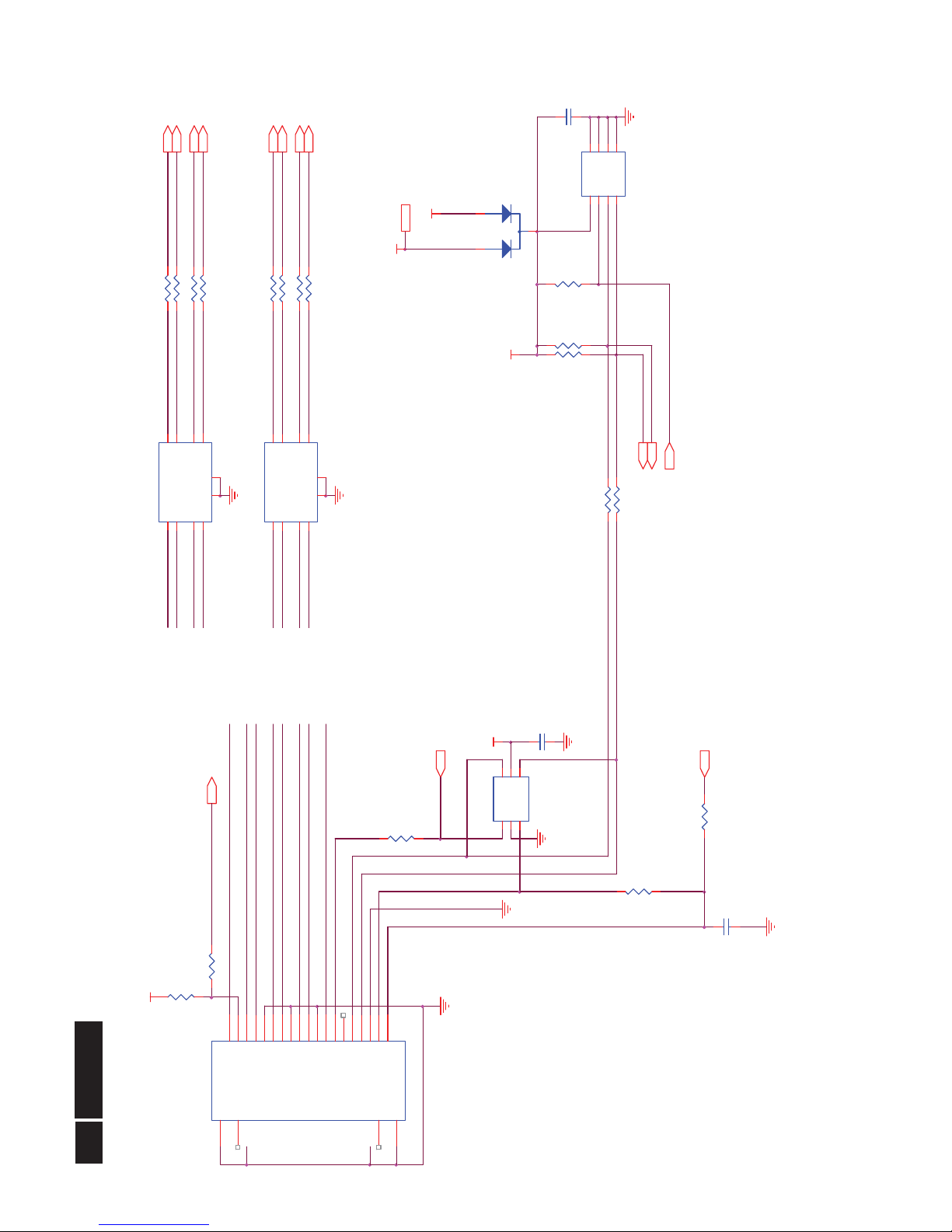
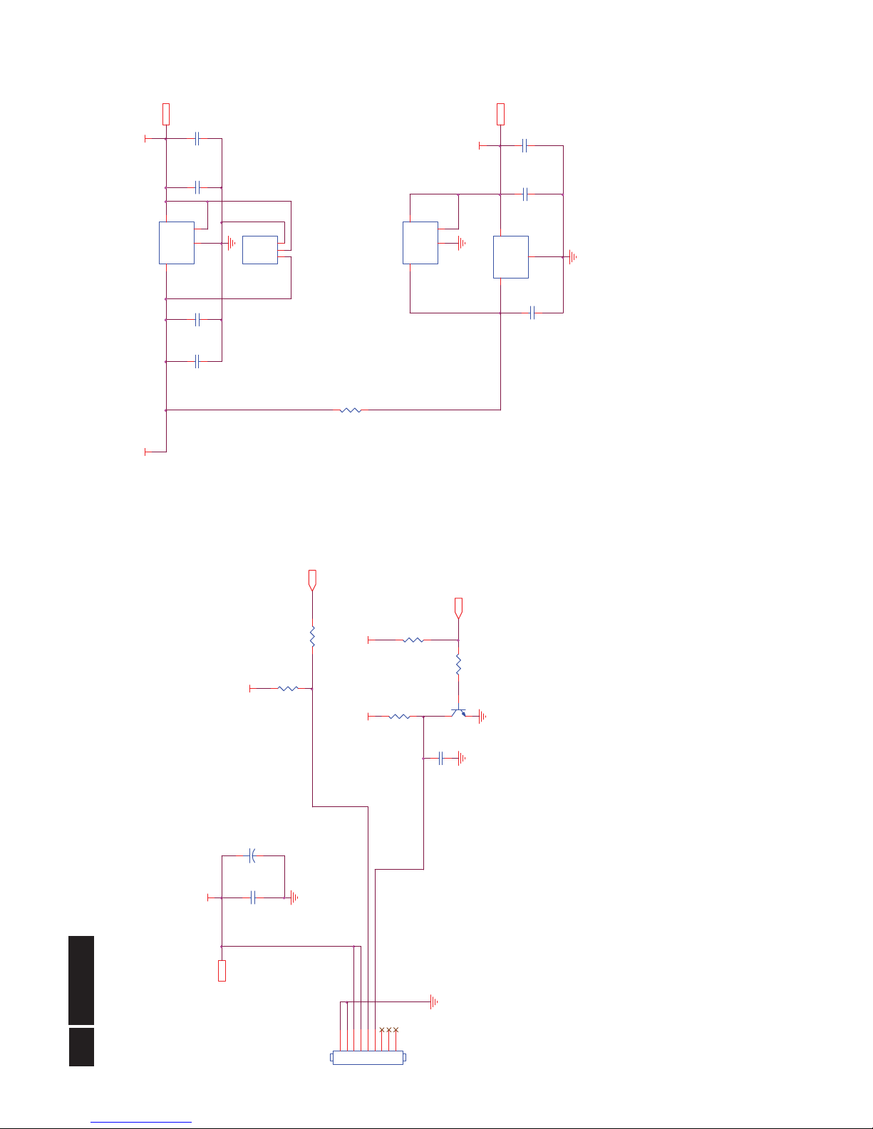
6.1 Scaler Board (715G4509M01000004K)
Remark: Parts position can be searched by using FIND function in PDF.
+5V_SB 4,5,6,7, 8
5V_ESD
VGA_G+
C105
5PF 50V
U106
AZC199-04S
123 4
5
6
I/O1
GND
I/O2 I/O3
VDD
I/O4
CN101
DB15
162738495
11
12
13
14
15
10
17 16
VGA_B+
R116
75R 1/16W 1%
R130 10R 1/16W 5%
R111 100R 1/16W 5%
R108
75R 1/16W 1%
DVI5V
+5V_SB
C112
NC
CN102
JACK
1
234
5
678
9
101112
13
141516
17
18
19
20
212223
24
26
25
27
28
DAT2-
DAT2+
2/4shield
DAT4-
DAT4+
DDC SCL
DDC SDA
VSYNC
DAT1-
DAT1+
1/3shield
DAT3-
DAT3+
+5V
SYNC GND
HPD
DAT0-
DAT0+
0/5shield
DAT5-
DAT5+
clk shield
clk+
clk-
GND
GND
GND
GND
R104 100R 1/16W 5%
R127 10R 1/16W 5%
DVI_SCL 5
R113
100R 1/16W 5%
R121 100R 1/16W 5%
C108
47N16V
R132 10R 1/16W 5%
DVI_SCL1
GNDG 5
DET_DVI
C103
22PF 50V
ESD_5V1
U104
AZC199-04S
1234
5
6
I/O1
GND
I/O2I/O3
VDD
I/O4
RX2- 5
VSYNC 5
V_Sync
R117 100R 1/ 16W 5%
DDCA_SCL5
VGA_B-
DDCA_SDA5
DDCA_SCL
DSUB_SDA
C109
5PF 50V
C101
NC
VGA_R-
R107
2K2 1/16W 5%
ZD104
RLZ5.6B
R114 100R 1/16W 5%
5V_ESD
ESD_5V1
DVI_SDA1
C104
22PF 50V
R101
100R 1/16W 5%
C102
47N16V
FB101
BEAD
1 2
C121
220N16V
RX1+ 5
R148
4K7 1/16W 5%
R152 10K 1/16W 5%
H_Sync
VGA_B+
V_Sync
R102
0R05 1/10W
R122 100R 1/16W 5%
ESD_5V1
C118
NC
DSUB_SCL
GNDR 5
+5V_SB
DSUB_5V
R105 100R 1/16W 5%
D102
BAV70
3
1
2
R103 100R 1/16W 5%
R119 100R 1/16W 5%
R126 10R 1/16W 5%
U108
M24C02-WMN6TP
123
45
678
A0A1A2
VSSSDA
SCLWPVCC
R106
2K2 1/16W 5%
C113
5PF 50V
VGA_G+
R118 100R 1/16W 5%
RX0+ 5
DET_DVII 5
C117
220N16V
RX2+ 5
DSUB_5V
DET_VGAI 5
U105
AZC199-04S
123 4
5
6
I/O1
GND
I/O2 I/ O3
VDD
I/O4
FB103
BEAD
1 2
FB102
BEAD
1 2
DSUB_SCL
VGA_R-
R112
75R 1/16W 1%
D103
BAV70
3
1
2
DDC_WP
5V_ESD
VGA_B-
DET_VGA
R136
22K 1/16W 5%
ESD_5V1
GNDB 5
BIN 5
VGA_R+
C106
47N16V
C110
47N16V
C115
100N 16V
C119
NC
R134 10R 1/16W 5%
R138
4K7 1/16W 5%
DVI_SD A1
R153 10K 1/16W 5%
R115 100R 1/16W 5%
DVI5V
DDC_WP4, 5
VGA_G-
RXC- 5
R109 100R 1/16W 5%
VGA_G-
R128 10R 1/16W 5%
R151
22K 1/16W 5%
DVI_SDA 5
VGA_B+
DSUB_SDA
H_Sync
FB105
300 OHM
R129 10R 1/16W 5%
C120
NC
U102
M24C 02-WMN 6TP
123
45
678
A0A1A2
VSSSDA
SCLWPVCC
VGA_R+
R149
4K7 1/16W 5%
FB106
300 OHM
RXC+ 5
FB104
300 OHM
HSYNC 5
DSUB_5V
U103
AZC199-04S
123 4
5
6
I/O1
GND
I/O2 I/ O3
VDD
I/O4
RX1- 5
DDCA_SDA
DET_VGA
C111
47N16V
RX0- 5
R120 1K 1/16W 5%
VGA_G+
DET_DVI
GIN 5
ESD_5V
R137
4K7 1/16W 5%
RIN 5
VGA_R+
DVI_SCL1
U107
AZC199-04S
1234
5
6
I/O1
GND
I/O2I/O3
VDD
I/O4
C114
47N16V
R131 10R 1/16W 5%
Input
!
18
Meridian 3
Remark: Parts position can be searched by using FIND function in PDF.
HDMIESD
HD1+
HD1+
HDMI1_D2- 5
HD0+
HD0-
CEC_CTR L 5
R514 100R 1/ 16W 5%
U504
M24C02-WMN6TP
123
45
678
A0A1A2
VSSSDA
SCLWPVCC
C501
100N 16V
HDMI_+5V
HD0-
HD1-
HDMI1_D1+ 5
HDMI1_CK+ 5
HD1+
HCK+
+5V_SB
HD0+
HDMI_HOTPLUG
+5V_SB 3,5,6,7,8
HD2-
R503 0R05 1/ 16W
C502
220N16V
CEC
U502
AZ1045-04F.R7G
1
234
5 6
789
10
IN1
IN2
GND
IN3
IN4 NC
NC
GND
NC
NC
U501
AZ1045-04F.R7G
1
234
5 6
789
10
IN1
IN2
GND
IN3
IN4 NC
NC
GND
NC
NC
HD2-
R508 0R05 1/ 16W
HD2+
HCK-
U503
AZC199-04S
123 4
5
6
I/O1
GND
I/O2 I/O3
VDD
I/O4
+5V_SB
R515 100R 1/ 16W 5%
R506 0R05 1/ 16W
CN501
HDMI
20
21
12345678910111213141516171819
22
23
TH1
TH2
D2+
D2 Shield
D2-
D1+
D1 Shield
D1-
D0+
D0 Shield
D0-
CK+
CK Shield
CK-
CE Remote
NC
DDC CLK
DDC DATA
GND
+5V
HP DET
TH3
TH4
HD0-
HD0+
R528 10K 1/16W 5%
DDC_WP3,5
HCK+
HDMIESD
R511
4K7 1/16W 5%
R513
22K 1/16W 5%
HD2+
R529
NC
HCK-
R517
100R 1/16W 5%
HD2-
HDMI1_SDA5
D501
BAT54C
3
1
2
HCK+
HDMI_+5V
R516
1K 1/16W 5%
DET_HDMI 5
HDMI1_D0+ 5
HD1-
HDMI1_D1- 5
HDMI1_CK- 5
HDMI1_SCL5
R507 0R05 1/ 16W
HDMI1_D2+ 5
HCK-
R510
NC
HDMI_DATA
R505 0R05 1/ 16W
HDMI1_D0- 5
HD2+
R512
4K7 1/16W 5%
R504 0R05 1/ 16W
HDMI_CLK
R501 0R05 1/ 16W
HDMI_HPD 5
R502 0R05 1/ 16W
C521
100N 16V
HD1-
HDMI
19
Meridian 3
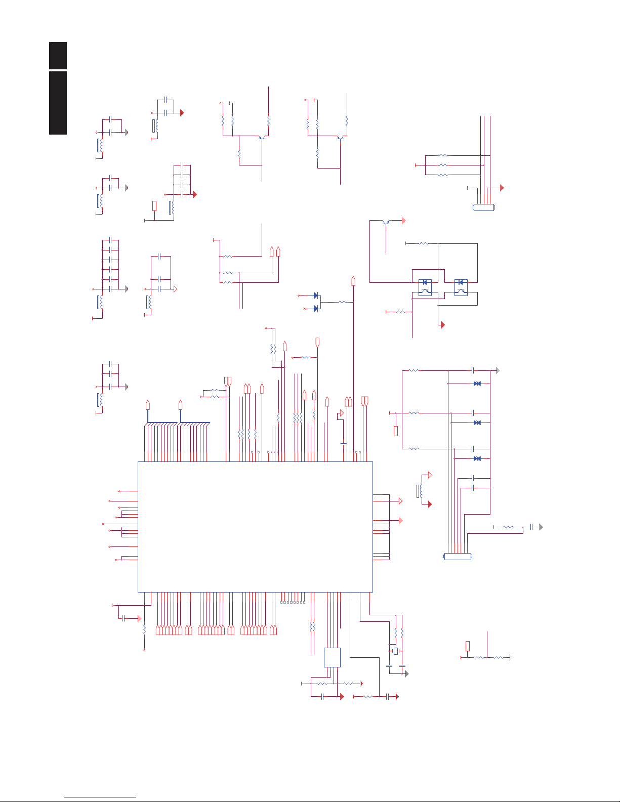
Remark: Parts position can be searched by using FIND function in PDF.
VCC3.3
OC2
NC/R BS311115
4 3
1 2
VSYNC3
KEY2
piovt
C432
100N 16V
VCC3.3
LED_ORG
R414
0R05 1/16W
OC1
NC
4 3
1 2
HDMI_HPD 4
AIN_L 3
RSTB
R409 100R 1/16W 5%
PB3
ZD402
NC/MLVG0402
12
C439 10uF 16V
R437NC
C433
NC/100 N 16V
BIN3
GNDG3
R418 100R 1/16 W 5%
RXC+3
piove_ power
ADC_VDD
EE_WP
PA1
5V_DET
Volume 7
LEDG
PA[0..9] 6
KEY1
R419
100K 1/16W 5%
PA0
HDMI1_SCL4
U401
NT68677UMFG/E
1
2
3
4
5
6
7
8
9
10
11
12
13
14
15
16
17
18
19
20
21
2223242526
27
28
29
3031323334
35
36
37
38
39
40
41
42
43
44
45
46
4748495051
52
53
5455
56575859606162
63
64
102
101
100
99
98
979695949392919089
8887868584838281807978
777675
74
7372717069
68
67
66
65
128
127
126
125
124
123
122
121
120
119
118
117
116
115
114
113
112
111
110
109
108
107
106
105
104
103
REXT
RX1C-
RX1C+
RX2C-
RX2C+
AGND
RX10-
RX10+
RX20-
RX20+
AGND
RX11-
RX11+
RX21-
RX21+
AVCC
RX12-
RX12+
RX22-
RX22+
ADC_GNDA
BIN1+
BIN1-
GIN1+
GIN1-
RIN1+
RIN1-
ADC_1V8
ADC_VDD
BIN0+
BIN0-
GIN0+
GIN0-
RIN0+
RIN0-
HSYNCI2
VSYNC I2
HSYNCI1
VSYNCI1/TOUTP
DGND
PB4*/DDC_SCL0*
PB5*/DDC_SDA0*
PB6*/DDC_SCL1*
PB7*/DDC_SDA1*
P30*/RXD*
P31*/TXD*/SPD IF*
PB0/ADC0/INTE0
PB1/ADC1/INTE1
PB2/ADC2/INTE2
PB3/ADC3/INTE3
PE2*/PWMA*/ DBC0*
CVDD
DVDD
AUDIO_VDDAUDIO_GND
I2S3/AIN1_R
I2S2/AIN1_L
I2S1/AIN0_R
I2S0/AIN0_L
WD
SCK/AOUT_R
MCLK/ AOU T_L
AUDIO_BY PASS
DGND
PC4/PWM8
PC2*/PW M6*
PC0*/PWM4*/C EC2*
CVDD
DGND
T0M
T0P
T1M
T1P
T2M
T2P
TCLK 1M
TCLK1P
T3M
T3P
DVDD
T4M
T4P
T5M
T5P
T6M
T6P
TCLK 2M
TCLK2P
T7M
T7P
DGND
PD6
PD5
PD4/AMUTE
SPI_CK
SPI_SI
SPI_SO
SPI_CE
P35*
P34*
DVDD
MVDD
AVCC
DGND
MVDD
PA7*/DDC_SDA3*
PA6*/DDC_SCL3*
PA5*/DDC_SDA2*
PA4*/DDC_SCL2*
PE1*/LPD_I N1*
PE0*/LPD_I N0*
CVDD
OSC_VDD
OSCO
OSCI
DGND
RSTB
PA3*/PWM3*/ADC7
PA2*/PWM2*/ADC6
PA1*/PWM1*/ADC5
PA0*/PWM0*/ ADC4/ DBC2*
PC7/PWM11
PC5/PWM9
PC3*/PWM7*/CEC3*
PC1*/PWM5*/LPD_OU T*
PE3*/PWMB*/ DBC1*
DVDD
PC6/PWM10/SPD IF
Adj_BACKLIGHT 8
R427
NC/2K2 1/ 16 W 5%
C412
100N 16V
R403
100K 1/16W 5%
Q403
NC
HDMI1_D0-4
C403
22UF 16V
R438NC/10K+-5%1/16W
R413 NC
OSCO
R445
3.9K 1%
VCC1.8 8
LEDA
R420
0oHM
ZD401
NC/MLVG0402
12
R452
NC/100R 1/ 16W 5%
VCC3.3
PB0
LED_GRN/BLUE
Add Heatsink ...
C423 22PF 50V
DDCA_SDA3
RX1+3
R444
3.9K 1%
C471
10uF 16V
HSYNC3
VCC3.3
VCC3.3
AOUT_L 7
SDA1
DVI_SDA3
SDA_Panel 6
PB1
R407 100R 1/16W 5%
VCC3.3
EE_WP
DVDD
X401
12MHz
R429
0 OHM +-5% 1/8W
C402
22UF 16V
DVDD
C408
100N 16V
PA[0..9]
R411 NC
SCL_Panel 6
OSCI
LEDG
RX0-3
DVDD
ADC_1V8
HDMI1_D1+4
DDCA_SCL3
KEY1
FB406
120 OHM
1 2
R415
2K2 1/16W 5%
C406
100N 16V
LED_ORG
VCC3.38
PS_DISTANCE
R439NC/10K+-5%1/16W
R428
10K 1/16W 5%
HDMI1_D2-4
DVDD
POWER
R450 NC
R435
0R05 1/16W
HDMI1_D0+4
HDMI1_D2+4
DVDD
KEY2
piovt
R405 10K 1/16W 5%
C480
100N 16V
RXC-3
+5V_SB
DVDD
LED_GRN/BLUE
R433
NC
C416
22UF 16V
R434
NC
PS_OUTPUT
C413
22UF 16V
CN404
NC
12345
AUDIO_VDD
VCC3.3
PB9
U402
Pm25LD020C-SCE
1
2
348
7
6
5
CE#
SO
WP#
GND
VDD
HOLD#
SCK
SI
Q402
LMBT3906LT1G
on_Panel 6
+5V_SB 3,4,6,7, 8
CVDD
C414
100N 16V
VCC3.3
CVDD
C401
220N16V
C410
100N 16V
R436
27K 1/16W 5%
R453
NC/100R 1/16W 5%
R416 100R 1/16 W 5%
R404 10K 1/16W 5%
R406
0R01 1/10W
C415
10uF 16V
VCC3.3
PB6
FB405
120 OHM
1 2
FB402
120 OHM
1 2
HDMI1_D1-4
DVI_VCC
VCC3.3
PB8
DVDD
PA4
PB4
DDCWP
CN401
CONN
1234567
DVDD
PA8
C409
100N 16V
GIN3
VCC3.3
C431
100N 16V
R412 10K 1/ 16W 5%
PS_ON
C405
100N 16V
C420
100N 16V
C404
100N 16V
on_BACKLIGHT 8
R417 100R 1/16 W 5%
A_VCC
PB7
RX1-3
DVDD
PS_ON
RIN3
WP
RX2-3
+5V_SB
PA2
PB[0..9] 6
R448
NC/4K7 1/ 1 6W 5%
GNDR3
DET_DVII 3
ADC_VDD
PB[0..9]
PA3
R422
100K 1/16W 5%
VCC1.8
+5V_SB
SDA1
R447
1K 1/16W 5%
WP
SCL1
C422
100N 16V
R425
0R01MAX 1/16W +-1%
R421
NC
Mute 7
PA6
PB2
piove_power
VCC1.8
5V_DET
FB407
120 OHM
1 2
R449
NC/4K7 1/ 1 6W 5%
AIN_R 3
D401
BAT54C
3
1
2
C436
NC
R44610K 1/16W 5%
+5V_SB
POWER
HDMI1_CK+4
AOUT_R 7
HDMI1_SDA4
R424
200K
PB5
R443
3.9K 1%
FB409
120 OHM
1 2
DVI_VCC
LEDA
R402
100K 1/16W 5%
FB404
120 OHM
1 2
R423 NC/0R05 1/16W
DET_VGAI 3
VCC3.3
R431
1MOHM 1/16W +/-5%
ADC_1V8
C419
100N 16V
C499
100N 16V
FB401
120 OHM
1 2
C418
100N 16V
A_VCC
SCL1
PS_OUTPUT
C470
10uF 16V
RX0+3
DET_HDMI 4
DDC_WP 3,4
+5V_SB
ZD403
NC/MLVG0402
12
AUDIO_VDD
C411
100N 16V
C434
NC/100 N 16V
C407
100N 16V
DVDD
PS_DISTANCE
R426
10K 1/16W 5%
TOUCH
C424 22PF 50V
C417
22UF 16V
Q401
LMBT3906LT1G
PA7
FB403
120 OHM
1 2
RX2+3
PA5
HDMI1_CK-4
GNDB3
DVI_VCC
R401
470R 1/16W 1%
DVI_SCL3
CEC_CTRL 4
PA9
C435
NC/100 N 16V
Scaler

!
20
Meridian 3
Remark: Parts position can be searched by using FIND function in PDF.
LVB2P
RXO2+
R306
56KOHM 1/16W
RXO1+
RXO1+
PB3
LVB2M
LVA3M
RXO2-
FB301
120 OHM
1 2
RXEC+
LVB0P
RXO1-
AO3401L
R303
4K7 1/16W 5%
LVB3M
LVB3M
LVB1M
RXE3-
LVA0M
+5V_SB
RXOC+
RXE1+
2
PB8
RXO0-
PB6
RXE0+
RXOC-
RXEC-
C301
100N 16V
D
LVB0M
LVA0P
RXOC+
PB[0..9]5
LVB3P
RXO1-
RXEC+
RXE3+
RXE3-
LVACKM
PB[0..9]
LVACKP
LVA3P
RXE2-
SCL_Panel
RXE1-
LVBCKM
SDA_Panel 5
LVB0M
Q301
NC
LVA1P
RXE1+
RXO0+
PA5
RXE0-
LVB2P
PANEL_VCC
RXO2+
LVACKM
PB4
LVA1M
LVA3P
R304
22K 1/16W 5%
+5V_SB 3,4,5,7,8
R308
10K 1/16W 5%
SCL_Panel 5
LVA2P
LVA3M
C306
22UF 16V
RXEC-
RXO2-
LVB3P
SDA_Panel
+5V_SB
LVB1P
PA4
RXE3+
LVB2P
RXOC-
LVBCKM
PA1
LVA0P
RXO1+
LVA2M
LVB1P
LVB3M
LVB1M
PB7
C304
100N 16V
RXO3-
SDA_Panel
1
PA9
PA0
PB0
CN409
NC/CONN
246
8
1012141618202224262830
1357911131517192123252729
C303
1UF16V
LVA3P
LVA0M
R307
NC
R301
220 OHM 1/4W
on_Panel5
RXE2+
RXE2+
LVACKP
PA2
LVA1P
RXO0-
LVACKP
RXO3+
RXE2+
PA8
RXO1-
LVBCKP
LVB1M
LVB1P
PA6
RXE1-
LVA0M
RXO0+
RXE1+
LVB2M
U301
AO4411
1
2
3
4
8
7
6
5
S
S
S
G
D
D
D
D
RXO0-
3
RXE3-
LVACKM
PANEL_VCC
PB1
LVB0P
RXE2-
RXE3+
LVA2P
LVB2M
RXO3-
R305
10K 1/16W 5%
LVBCKP
RXOC-
LVA3M
RXO2+
LVA1M
RXO3-
RXE1-
PANEL_VCC
PB9
LVA0P
RXE0+
PB2
RXE2-
LVB0P
LVB0M
Q302
LMBT3904LT1G
RXO0+
C302
220N16V
LVA1M
RXE0-
LVA2P
LVA1P
LVA2M
RXE0-
S
PA[0..9]
RXO2-
C305
22UF 16V
LVA2M
G
PB5
LVBCKM
R302
220 OHM 1/4W
PA3
RXO3+
RXEC-
LVBCKP
PA7
RXO3+
RXEC+
RXE0+
LVB3P
PA[0..9]5
RXOC+
CN408
CONN
123456789
101112131415161718192021222324252627282930
Panel Interface
21
Meridian 3
Remark: Parts position can be searched by using FIND function in PDF.
C604
100N 25V
Volume5
FB609
120 OHM
1 2
C620
220pF 50V
AIN_R 7
AOUT_L5
+5V_AUDIO
R625
10K 1/16W 5%
R626
10K 1/16W 5%
OUT-L-
VOL
C605
1uF 10V
FB607
120 OHM
1 2
R614
56R 1/16W 5%
+5V_AUDIO
R613
10K 1/16W 5%
FB602 120 OHM
1 2
C619
10uF 16V
AIN_L 7
OUT-L-
C607 100P 50V
C622
220pF 50V
C613
10uF 16V
HP_L
OUT-R-
R617
1K 1/16W 5%
R607 100R 1/ 16 W 5%
HP_SENSE
R616
56R 1/16W 5%
CN605
CONN
123
4
R608
10K 1/16W 5%
OUT-L+
L
Mute5
HP_SENSE
+5V_AUDIO
HP_R
R627
470R 1/16W 5%
OUT-R-
R611
9K1 1/16W 5%
R604
10K 1/16W 5%
CN602
PHONEJACK
524316789
1011121314
R619
100R 1/16W 5%
+5V_SB
3,4,6
+5V_AUDIO
C617
1uF 10V
R622
0R05 1/16W
MUTE-1
HP_R
+
C609
220UF 16V
C616
1uF 10V
C626
0.47UF 10V
FB606
120 OHM
1 2
+5V_AU DI O
OUT-L+
HP_R
R621
0R05 1/16W
C612
1uF 10V
C603
22UF 16V
HP_L
Q601
LMBT3904LT1G
MUTE-1
R612
10K 1/16W 5%
R601
10K 1/16W 5%
R618
100K1/16W
FB601 120 OHM
1 2
FB603 120 OHM
1 2
D601
LL4148
C611
1uF 10V
+
C608
220UF 16V
C631
1uF 10V
+5V_SB
R609
10K 1/16W 5%
C606
100P 50V
CN604
NC/CONN
12345
+5V_AUDIO
FB608
120 OHM
1 2
C623
220pF 50V
C610
1uF 10V
C621
220pF 50V
R610
9K1 1/16W 5%
C615
100N 25V
R
MUTE-1
OUT-R+
HP_L
VOL
U601
PAM8007NHR
1
4
6
24
3
17 8
2
22
23
5
10
20
14
21
15
19
11
718
9
12
16
13
+OUT L
-OUTL
/ MUTE
+OUTR
PGNDL
INR INL
PGNDL
PGNDR
PGNDR
PVDDL
VDC
PVDDR
VREF
-OUTR
LINE/EAR
/ SHDN
Volume
VDDGN D
EarInL
EarOutL
EarInR
EarOutR
R615
1K 1/16W 5%
R605
10K 1/16W 5%
FB604 120 OHM
1 2
Q604
LMBT3904LT1G
OUT-R+
+
C601
470uF 16V
R602
1K 1/16W 5%
C614
1uF 10V
+5V_AU DI O
C630 1uF 10V
C625
0.47UF 10V
HP_SENSE
R606
10K 1/16W 5%
C618
1uF 10V
R620
0R05 1/16W
AOUT_R
5
+5V_AUDIO
+5V_AUDIO
C602
100N 16V
R630
0R05 1/10W
Q603
LMBT3906LT1G
1
23
CN601
NC/CONN
123
Audio
!
22
Meridian 3
Remark: Parts position can be searched by using FIND function in PDF.
+
C702
100UF25V
VCC3.3+5V_SB
Adj_BACKLIGHT 5
Both 223 and 252
foot-print
C709
100N 16V
VCC1.8
R702
10K 1/16W 5%
C704
22UF 16V
VCC3.3
C705
100N 16V
+5V_SB
3,4,6
BKLT-VBRI
C711
100N 16V
C706
22UF 16V
on_BACKLIGHT 5
U704 TO252 GOI
NC/AME8815BECS180Z
3 2
1
VI VO
GND
ON/OFF
R704
22K 1/16W 5%
VCC3.3 5
C708
100N 16V
R705
1K 1/16W 5%
+5V_SB
U702
NC/AP1117D33L-13
TO252GOI
1
2
3
ADJ(GND)
VOUT
VIN
C707
22UF 16V
Q701
LMBT3904LT1G
BKLT-EN
CN701
CONN
123456789
VCC1.8 5
VCC3.3+5V_SBDIM
Both 223 and 252
foot-print
C703
100N 16V
C701
100N 16V
R708
10K 1/16W 5%
R706
100R 1/16W 5%
U703
AP2114H-1.8TRG1
3 2
1
4
VI VO
GND
4
R710
5.1 OHM 2W
U701
AP2114H-3.3TRG1
3 2
1
4
VI VO
GND
4
Power
23
Meridian 3
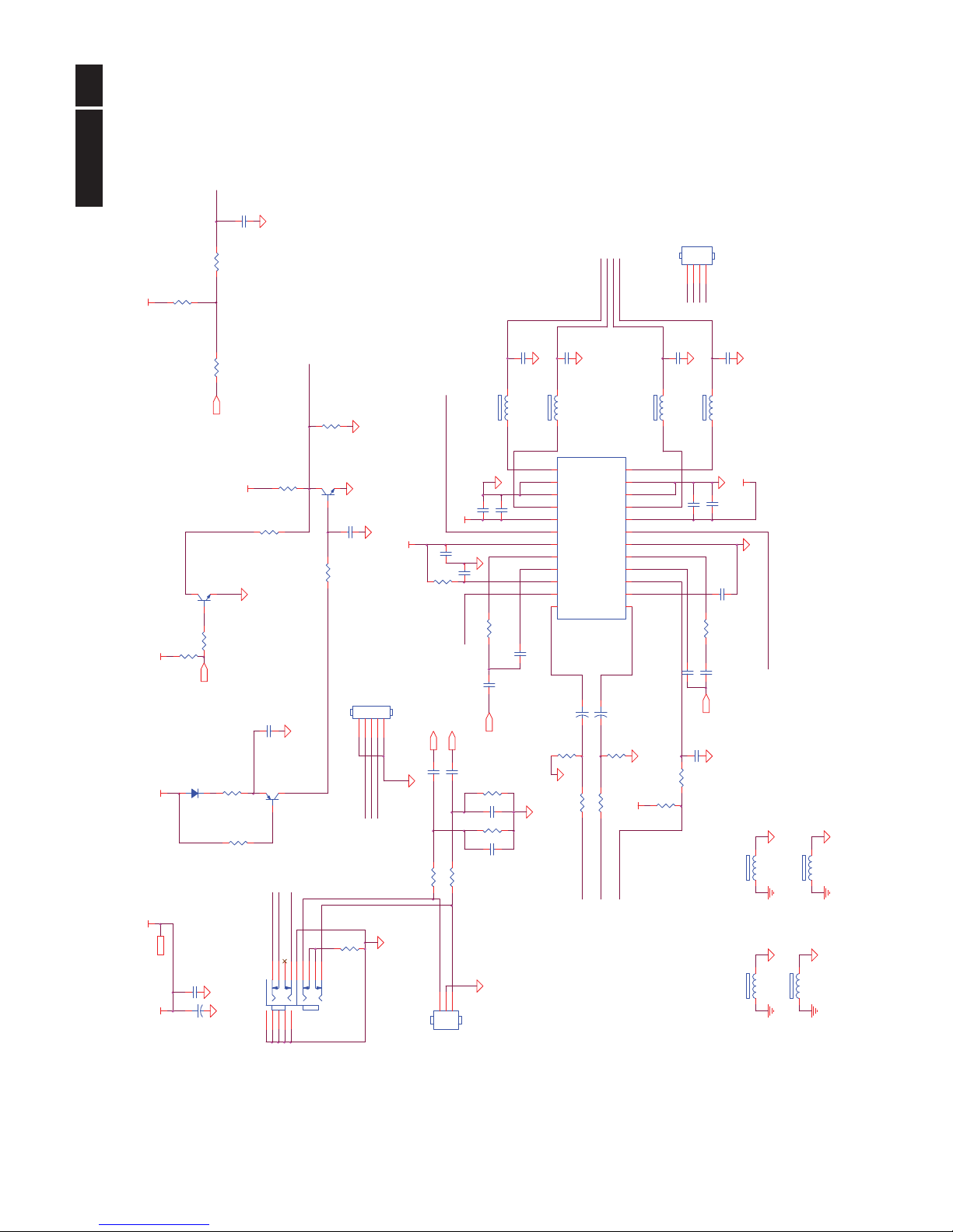
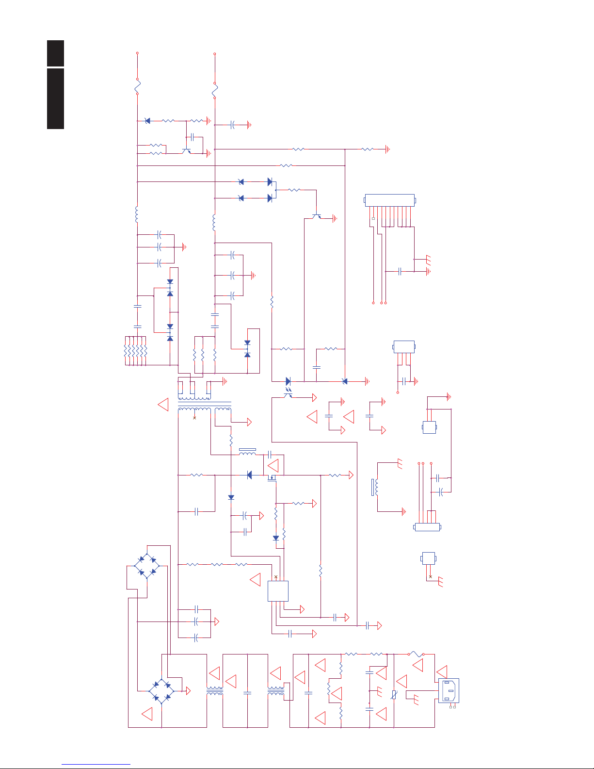
6.2 Power Board
Adapter 715G3727P0B0040030
Remark: Parts position can be searched by using FIND function in PDF.
+16V
R935 100 OHM 1/4W
+
C908
47uF 50V
R912
820OHM 1/4W +/ -5%
-
+
BD901
GBL408
2
1
3
4
C924
47nF 50V
+
C905A
220uF/450V/NC
R939
1K 1/8W
GND1
GND
1
2
+16V
!
4A/250V
R907
100K OMH 2W +-5%
R922
NC
F903
FUSE
R938
10K 1/8W 1%
C929
2200pF 500V
R923
NC
C909
220P 50V
R904
5.1K 1/4W
!
!
+5V
!
C901
1000pF 250V
NC/Q904
DTC144WKA
FB902
BEAD
1 2
C942
2200pF 500V
LOAD=16V/3.0A
+
C919
100uF 50V/N C
C920
0.001uF/NC
R947
820 OHM 2W
CN901
SOCKET
1
3
2
4
5
L
E
N
TH1
TH2
IC903
PC123X2YFZOF
12
43
Q901
SMK0870F
R924
470 OHM 1/8W
+
C944
680UF25V
D909
FME-220A
1
2
3
CN802
NC
1
2
FB901
BEAD
12
!
F901
FUSE 4A 250V
C907
100N 50V
L901
30mH
1
4
2
3
R918100 OHM 1/4W
R919100 OHM 1/4W
L902
4mH
1
2
4
3
!
F904
FUSE
CN801
NC
12345
R902
680K 1/4W
R911
10 OHM 1/4W
C943
2200pF 500V
NC/CN903
HARNESS
123
4
R926
3KOHM 1/10W
L904
3.5uH
ON/OFF
R901
680K 1/4W
For INVERTER /
USB*4(option)
!
Q903
KTD1028
C932
1nF 50V
C900
3300pF 250V
R940
56K +-1% 1/10W
RV903
NC
!
NC/R913
1K 1/8W 1%
+
C939
680UF25V
T901
80GL32P 6 N
2
3
4
5
6
7
8
91011
12
C904
0.22UF275V/NC
For MAIN/AUDIO
Circuit
R961 100 OHM 1/4W
C921
NC/1000PF/250VAC
+5V
R930
2.4K 1/10W
NC/ZD922
GDZJ5. 6B
1 2
DIM
R903
680K 1/4W
R962 100 OHM 1/4W
+
C941
680UF25V
R905
5.1K 1/4W
!
C912
2200pF 500V
HV
R925
1K 1/8W 1%
CN902
Wire Harness
123456789
10
11
NC/ZD921
TZX20B
1 2
NR901
NTCR/NC
!
L903
3.5uH
!
NR902
NTCR
D901
PS102R
R906
5.1K 1/4W
IC901
LD7576AGR
123
4 5
678
CT
COMPCSGNDOUT
VCC
NC
HV
R943
470 OHM 1/8W
R920100 OHM 1/4W
+16V
+
C917
680UF25V
D907
NC
1
2
3
ON/OFF
+
C905
150uF 450V
NC/D904
BAV70
3
1
2
!
LOAD=5V/2.85A
R909
1 OHM 1/4W
D900
BYV26EGP
1 2
R946
820 OHM 2W
+
C916
680UF25V
C906
1500PF2KV
C928
10N 50V
+
C915
470UF16V
C913
47N 50V
R921
NC
C903
0.47UF275V
R914
0.27 OHM 5% 2W
IC904
AS431AZTR-E1
090626
!
C911
NC/1500PF2KV
ZD902
TZX18B
1 2
C931
100N 50V
D906
FME-230B
1
2
3
-
+
BD902
GBU408/NC
2
1
3
4
!
!
C937
NC/100pF/2KV
R910
10 OHM 1/4W
D903
1N4148
R927
3.3K +-1% 1/10W
C902
1000pF 250V
!
DIM
C930
100N 50V
+
C918
680UF25V
!
!
24
Meridian 3
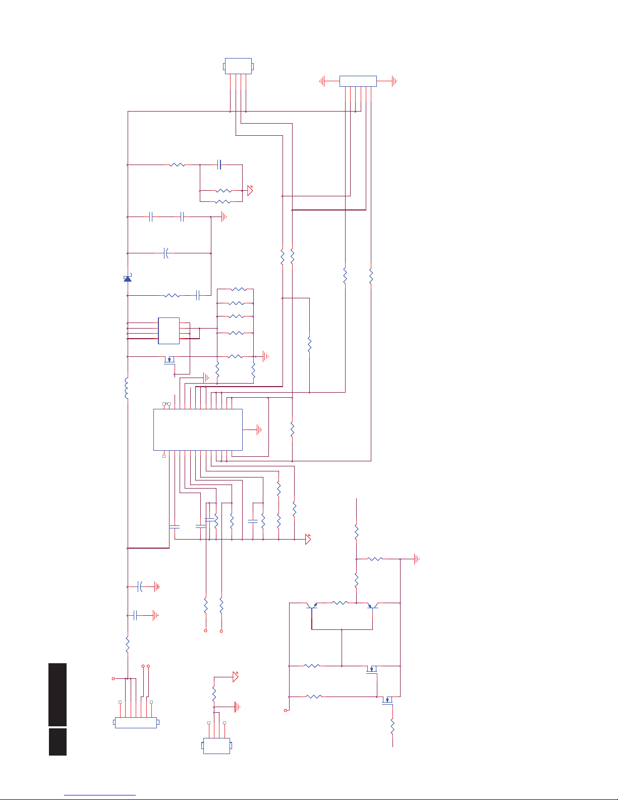
Converter 715G4013P03001004S
Remark: Parts position can be searched by using FIND function in PDF.
R819
20K 1/10W
U801
MP3389EF
123456789
1011121314 15
16171819202122232425262728
29
NC
VIN
VCC
COMPENDBRT
GND
OSC
ISET
BOSC
LED12
LED11
LED10
LED9 LED8
LED7
LED6
LED5
LED4
LED3
LED2
LED1
OVP
ISENSE
PGND
GATE
VFAULT
NC
E-Pad
R822
NC/
C803
470N 25V
C806
100pF 50V
CN806
CONN
12345
6
78
R813
1 OHM +-5% 1/8W
R803
16.5K OHM +-1% 1/10W
C810
0.47uF 50V
Gate
R815
0R05OHM1/8W
Q805
NC/
R821
NC/
R806
1K 1/10W
DIM
OVP
+14.5V
Q804
NC/
R814
1 OHM +-5% 1/8W
F801
0R05 4A 1/4W
R817
1 OHM +-5% 1/8W
ON/OFF
R804
100K 1/10W
R811
1 OHM +-5% 1/8W
CN805
NC/CONN
123
4
R828
1 OHM +-5% 1/8W
CN801
1234567
Gate
R808
1K 1/10W
R829
NC
R801
10 OHM 1% 1/4W
R831
1 OHM +-5% 1/8W
R833
NC
+
C809
100uF 50V
R830
NC
R823
0R05OHM1/8W
D801
SK310B
1 2
C808
NC
C804
470N 25V
DR
DIM
Q803
NC/
R825
NC
R810
20K 1/10W
R802
270K 1%
ON/OFF
Q802
NC/
R832
1 OHM +-5% 1/8W
R812
1 OHM +-5% 1/8W
C805
100pF 50V
R826
3.3R 1/ 8W 5%
R827
1 OHM +-5% 1/8W
DR
R820
NC/
+
C807
4.7UF 100V
C802
68NF 5 0V
R824
NC
+14.5V
Q806
APM8005KCTRG
1
2
3
4 5
6
7
8
S1
G1
S2
G2 D2
D2
D1
D1
R818
0R05 1/4W
C811 100pF 50V
CN802
123
4
L801
47uH
OVP
R809
8.2K1/10W
R816
1 OHM +-5% 1/8W
NC/Q801
AOD482
R807
20K 1/10W
DR
R805
300KOHM 1/10W
C801
470N 25V
25
Meridian 3
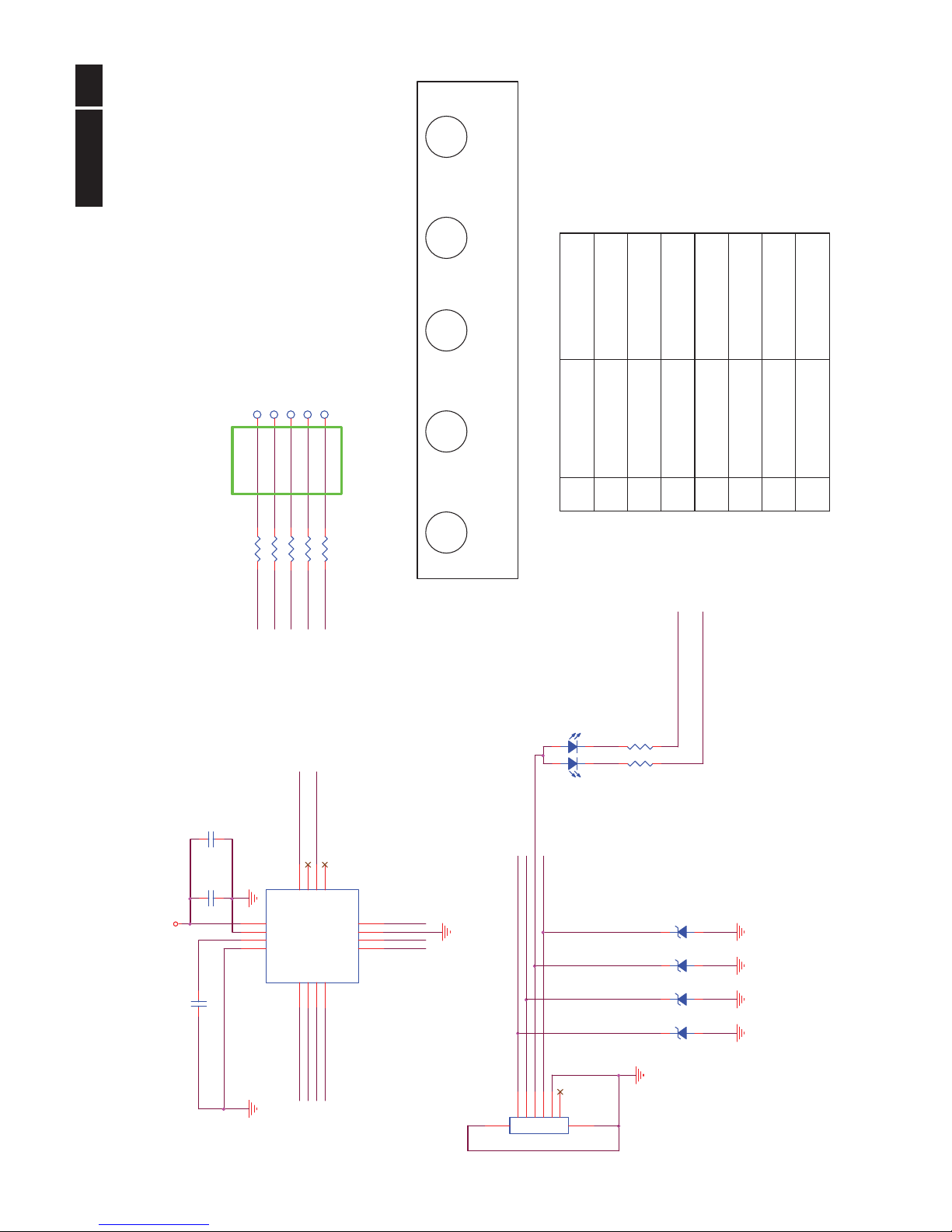
6.3 Key Board (715G4512K01000004S)
Remark: Parts position can be searched by using FIND function in PDF.
LED VCC
RIGHT
LED_Blue
I2C SDA
Button_5
Buttons
T04
Volume/
Back
CN401
R005 560OHM +-5% 1/10W
2
GND
Button_5
Button_1
1
Input/
Up
VCC
White
Yellow
LED001
LED
1
2 3
4
4
LEFT
5
Button_2
POWER KEY#
INPUT
T03
GND
I2C_SDA
LED_Amber
LED R
Button_4
SmartImage
Lite/Down
CN001
LED_Blue
R007
7K5 1/10W 5%
Button_4
C001
1000pF 50V
C002
10uF 6.3V
R006
NC
NC
C003
0.1UF50V
U001
CG7246AM
123
4
5
6
7
8
91011
12
13
14
15
16
GP0[0]
GP0[1]
I2C SCL
I2C SDA
GP1[0]
GP1[1]
VSS
GP1[2]
GP1[3]
GP1[4]
XRES
GP0[2]
VDD
GP0[3]
CSInt
GP0[4]
ZD003
NC/UDZSNP5.6B
1 2
VCC
Button_3
I2C SCL
Button_3
R001 560OHM +-5% 1/10W
3
LED_Amber
ZD001
NC/UDZSNP5.6B
1 2
KEY2
Button_2
I2C_SCL
I2C_SDA
R004 560OHM +-5% 1/10W
R002 560OHM +-5% 1/10W
Menu/OK
6
7
LED_Vcc
ZD004
NC/UDZSNP5.6B
1 2
ZD002
NC/UDZSNP5.6B
1 2
T01Button_1NCT02
T05
VCC
MENU
I2C_SCL
LED G
CN001
CONN
12345
6
78
Power
Power
KEY1
R003 560OHM +-5% 1/10W
 Loading...