

Philips 221TE4LB/57, 231TE4LB/57, 231TE4LB/55, 221TE4LB/55, 231TE4LB/45 Service Manual
...
21.5"&23"TV Monitor Chassis: Meridian 4
Service
Service
Service
Description Page
Table of Contents.........................................………….1
Revision List................................................………….2
Important Safety Notice…………................................3
1. General Specifications….........................................5
2. TV Monitor Description………….............................6
3. Operation Instructions….........................................7
3.1 Front Controls and Indicators……………………...7
3.2 Connection Overview……….................................7
3.3 Remote Control ……………….……………….……9
4. Input/output Specification..........................……….11
4.1 Input Signal Connector...........................………..11
4.2 Factory Preset Display Modes............................13
4.3 Pixel Defect Policy…………………………………13
4.4 Failure Mode of Panel……………………………16
5. Block Diagram…………………………................17
5.1 Scaler Board....................................………….....17
5.2 Power Board.....................................…………....18
6. Schematic Diagram.............................................. 19
Description Page
6.1 Scaler Board………………………………….……19
6.2 Power Board.................................................…...39
6.3 IR Board…….……………………..….……………43
6.4 Key Board…….……………………………………44
7. PCB Layout………………………………………...45
7.1 Scaler Board……………………………………...45
7.2 Power Board………….……………………………47
7.3 IR Board………...…………………………………50
7.4 Key Board………...………………………………50
8. Wiring Diagram………………………………….…..51
9. Scaler Board Overview…………………………....52
10. Mechanical Instructions………………………....53
11. Trouble Shooting…….…….………………………55
12. ISP Instructions...…............................................58
13. White Balance, Luminance Adjustment............59
14. Monitor Exploded View…....................................60
15. Recommended & Spare Parts List...…............... 61
16. General Product Specification………….………63
SAFETY NOTICE
ANY PERSON ATTEMPTING TO SERVICE THIS CHASSIS MUST FAMILIARIZE HIMSELF WITH THE CHASSIS
AND BE AWARE OF THE NECESSARY SAFETY PRECAUTIONS TO BE USED WHEN SERVICING
ELECTRONIC EQUIPMENT CONTAINING HIGH VOLTAGE
REFER TO BACK COVER FOR IMPORTANT SAFETY GUIDELINES
Copyright 2012 Philips Consumer Lifestyle Subject to modification ○K Jul.13, 2012
221TE4LB/57
231TE4LB/57
221TE4LB/55
231TE4LB/44
231TE4LB/55
231TE4LB/45
CAUTION: USE A SEPARATE ISOLATION TRANSFOMER FOR THIS UNIT WHEN SERVICING
Meridian 4
2
Revision List
Version Release Date Revision History
A00 Feb.06,2012 Initial release, Draft Version
A01 May.15,2012
Add CTN model:
221TE4LB/55, 231TE4LB/44 and 231TE4LB/55
A02 Jul.13, 2012
Add CTN model: 231TE4LB/45

3
Meridian 4
Important Safety Notice
Read and understand all instructions before you use your TV. If damage is caused by failure to follow instructions,
the warranty does not apply.
Safety
Risk of electric shock or fire!
Never expose the TV to rain or water. Never place liquid containers. Such as vases, near the TV. If liquids
are split on or into the TV, disconnect the TV from the power outlet immediately. Contact Philips Consumer
Care to have the TV checked before use.
Never place the TV, remote control or batteries near naked flames or other heat source, including direct
sunlight. To prevent the spread of fire, keep candles or other flames away from the TV, remote control and
batteries at all time.
Never insert objects into the ventilation slots or other openings on the TV.
When the TV is swiveled ensure that no strain is exerted on the power cord. Strain on the power cord can
loosen connections and cause arcing.
Risk of short circuit or fire!
Never expose the remote control or batteries to rain, water or excessive heat.
Avoid force coming onto power plugs. Loose power plugs can cause arcing or fire.
Risk of injury or damage to the TV!
Two people are required to lift and carry a TV that weights more than 25 kg.
When stand mounting the TV, use only the supplied stand. Secure the stand to the TV tightly. Place the TV
on a flat, level surface that can support the combined weight of the TV and stand.
When wall mounting the TV, use only a wall mount that can support the weight of the TV. Secure the wall
mount to a wall can support the combined weight of the TV and wall mount. Koninklijke Philips Electronics
N.V. bears on responsibility for improper wall mounting that result in accident, injury or damage.
Risk of injury to children! Follow these precautions to prevent the TV from toppling over and causing injury to
children:
Never place the TV on a surface covered by a cloth or other material that can be pulled away.
Ensure that no part of the TV hangs over the edge of the surface.
Never place the TV on tall furniture (such as a bookcase) without anchoring both the furniture and TV to the
wall or a suitable support
Educate children about the dangers of climbing on furniture to reach the TV.
Risk of overheating! Never install the TV in a confined space. Always leave a space of at least 4 inches around
the TV for ventilation. Ensure curtains or other objects never cover the ventilation slots on the TV.
Risk of damage to the TV! Before you connect the TV to the power outlet, ensure that the power voltage
matches the value printed on the back of the TV. Never connect the TV to the power outlet if the voltage is
different.
Risk of injury, fire or power cord damage! Never place the TV or any objects on the power cord.
To easily disconnect the TV power cord from the power outlet, ensure that you have full access to the power
cord at all times.
Meridian 4
4
When you disconnect the power cord, always pull the plug, never the cable.
Disconnect the TV from the power outlet and aerial before lightning storms. During lightning storms, never touch
any part of the TV, power cord or aerial cable.
Risk of hearing damage! Avoid using earphones or headphones at high volumes or for prolonged periods of
time.
If the TV is transported in temperatures below 5℃, unpack the TV and wait until the TV temperature matches
room temperature before connecting the TV to the power outlet.
Screen Care
Avoid stationary images as much as possible. Stationary images are images that remain on-screen for
extended periods of time. Examples include: on-screen menus, black bars and time displays. If you must use
stationary images, reduce screen contrast and brightness to avoid screen damage.
Unplug the TV before cleaning.
Clean the TV and frame with a soft, damp cloth. Never use substances such as alcohol, chemicals or household
cleaners on the TV.
Risk of damage to the TV screen! Never touch, push, rub or strike the screen with any object.
To avoid deformations and color fading, wipe off water drops as soon as possible.
Recycling
Your product is designed and manufactured with high quality materials and components, which can be recycled
and reused. When you see the crossed-out wheeled bin symbol attached to a product, it means the product is
covered by the European Directive 2002/96/EC:
N
ever dispose of your product with other household waste. Please inform yourself about the local rules on the
separate collection of electrical and electronic products. The correct disposal of your old product helps prevent
potentially negative consequences for the environment and human health.
Your product contains batteries covered by the European Directive 2006/66/EC, which cannot be disposed of with
normal household waste.
Please inform yourself about the local rules on the separate collection of batteries. The correct disposal of batteries
helps prevent potentially negative consequences for the environment and human health.
The most updated user manual on line
The contents of the user manual are subject to change. Please refer to www.philips.com/support for the most
updated user manual info reference.

5
Meridian 4
1. General Specifications
Model 221TE4L/223TE4L
Picture / Display
Aspect Ratio 16:9
Resolution 1920 x 1080 @ 60Hz
Panel Typical
Pixel Pitch
221TE4L: 0.24825(H) x 0.24825(W)mm
231TE4L: 0.265(H) x 0.265(W) mm
Brightness: 250cd/m2
Contrast 1000:1
Rear Connectors
AV INPUT
COMPONENT INPUT (Y Pb Pr and AUDIO L/R)
PC IN (VGA and AUDIO IN)
HDMI
SPDIF OUT
TV ANTENNA
Side Connectors
HDMI
USB
HEADPHONE
Power Consumption
221TE4L < 55W
223TE4L < 60W
Standby <1W
AC-input 100 V ~ 240 V, 50/603Hz
Temperature
Operating
0C ~ 40 C
Storage
-10C ~ 50C
Tuner
NuTune FK1604
NTSC Front-end (Vertical Mount )
Television System
PAL-M/PAL-N / ISDB-T, Sound System: M
Channel Coverage
VHF: 2 through 13; UHF: 14 through 69, Cable TV
Frequency range
55.25MHz to 859.25MHz
IF Frequency
Analog Picture: 45.75MHz
Analog Sound: 41.25MHz
Impedance
75 ohm terminated
Note: Product information is subject to change without notice. For detailed product information, go to
www.philips.com/support
Meridian 4
6
2. TV Monitor Description
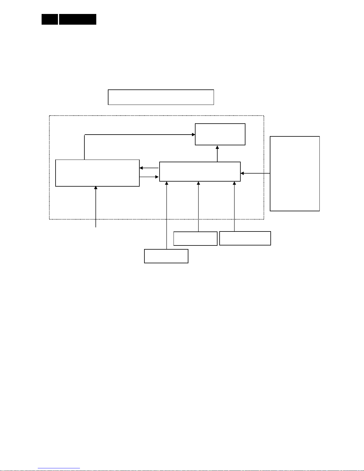
The TV monitor will contain a scaler board, a power board, an IR board and a key board. The scaler board houses
the flat panel control logic, brightness control logic and DDC.
The power board will provide AC to DC Inverter voltage to drive the backlight of panel and the scaler board chips
each voltage.
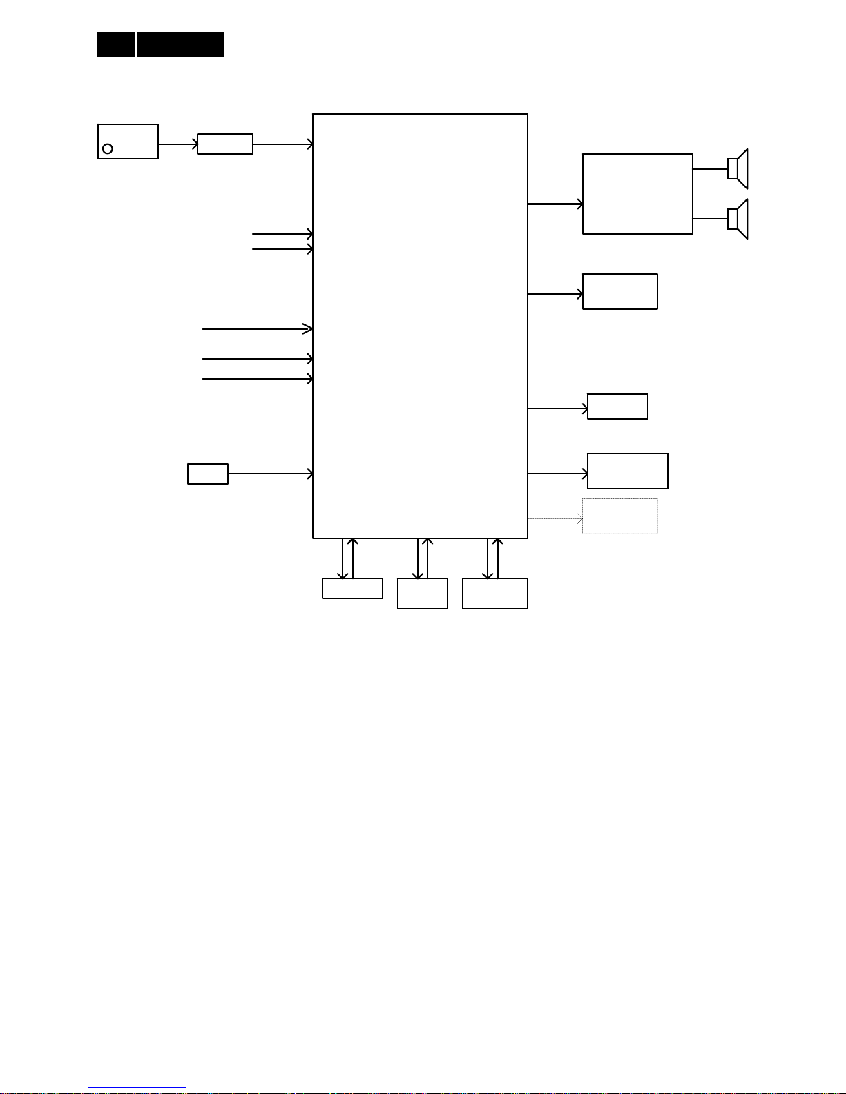
TV Monitor Block Diagram
AC-IN
100V-240V
Power Board
(Include: Power, LED Driver)
LED Panel
Scaler Board
VGA
USB
HDMI
SPDIF
AUDIO
TUNER
COMPONENT
AV Signal, DDC
Key Board
HOST Computer
IR Board

7
Meridian 4
3. Operating Instructions
3.1 Front and side controls
1.
POWER: Switch the monitor on or off. The
monitor is not powered off completely unless it is
physically unplugged.
2.
SOURCE: Select an input source.
Return to the previous screen or exit from the
on-screen menu.
3.
MENU/OK: Display the on-screen menu.
Confirm a selection.
4. CH +/-: Switch to the next or previous channel.
5. VOL+/-: Increase or decrease volume.
6. Power Indicator: Red LED: RC standby mode. /
PC standby mode.
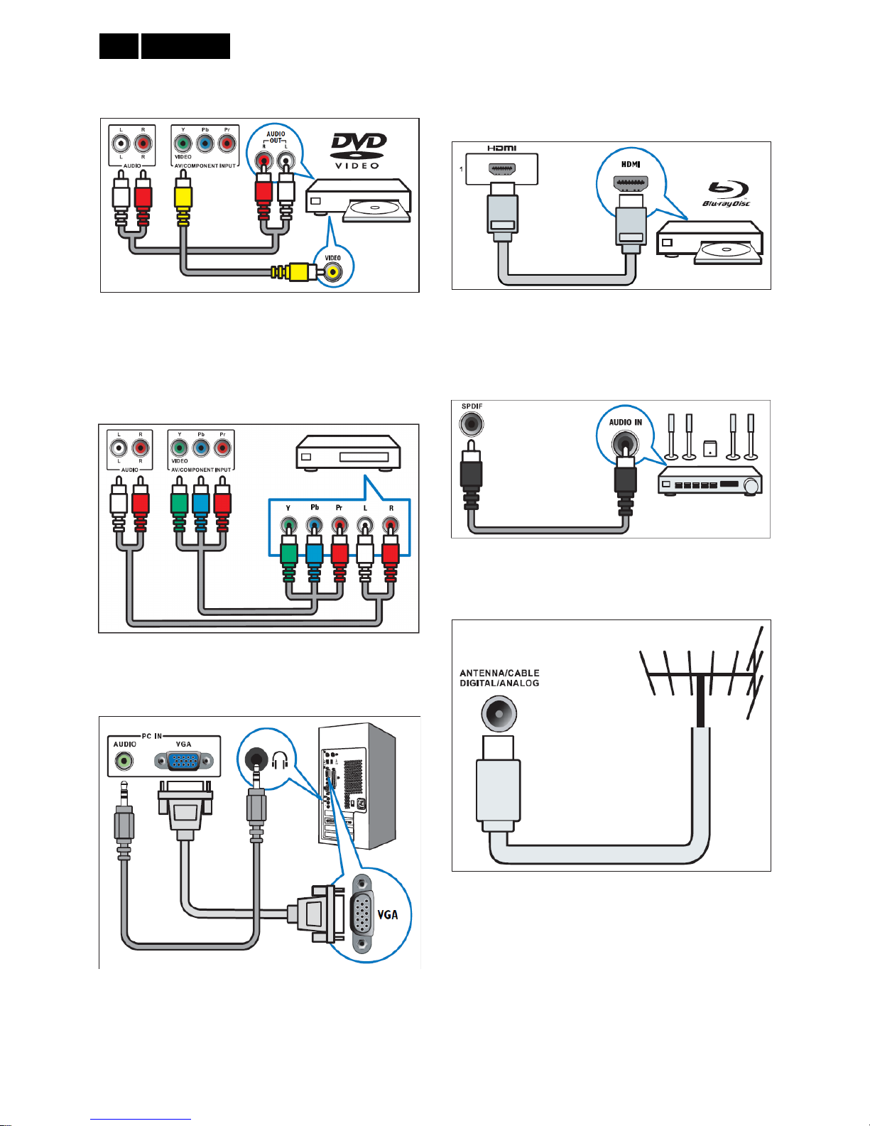
3.2 Connection Overview
Back Connector
Meridian 4
8
1. AV INPUT
Audio and video input from an AV device
2. COMPONENT INPUT (Y Pb Pr and AUDIO L/R)
Analogue audio and video input from analogue or
digital devices such as DVD players or game
consoles.
3. PC IN (VGA and AUDIO IN)
Audio and video input from a computer
The connection via VGA requires an additional audio
cable.
4. HDMI
Digital audio and video input from high-definition
digital devices such as Blu-ray players
5. SPDIF OUT
Digital audio output to home theaters and other digital
audio systems.
6. TV ANTENNA
Signal input from an antenna, cable or satellite
9
Meridian 4
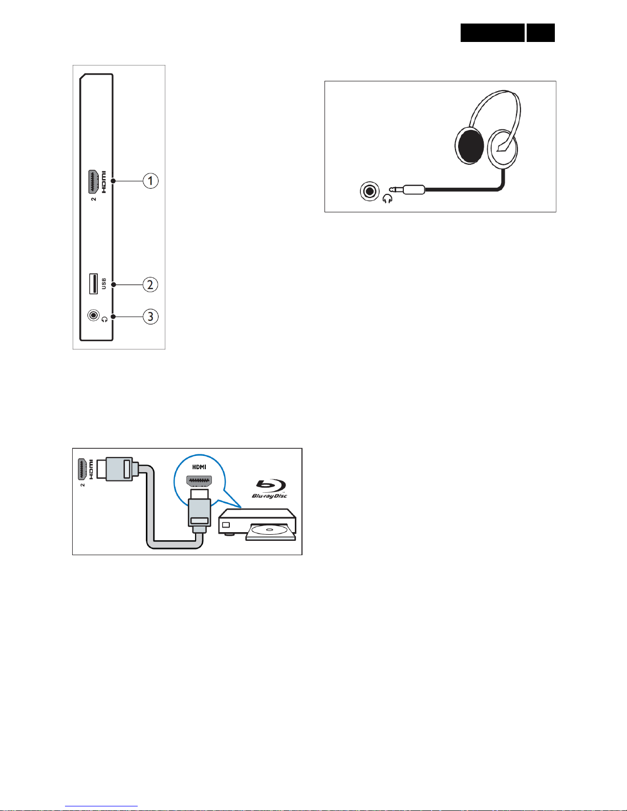
Side connector
1. HDMI
Digital audio and video input from high-definition digital
devices such as Blu-ray players.
2. USB
For music and photo
3. HEADPHONE
Audio output to your headphones.
Meridian 4
10
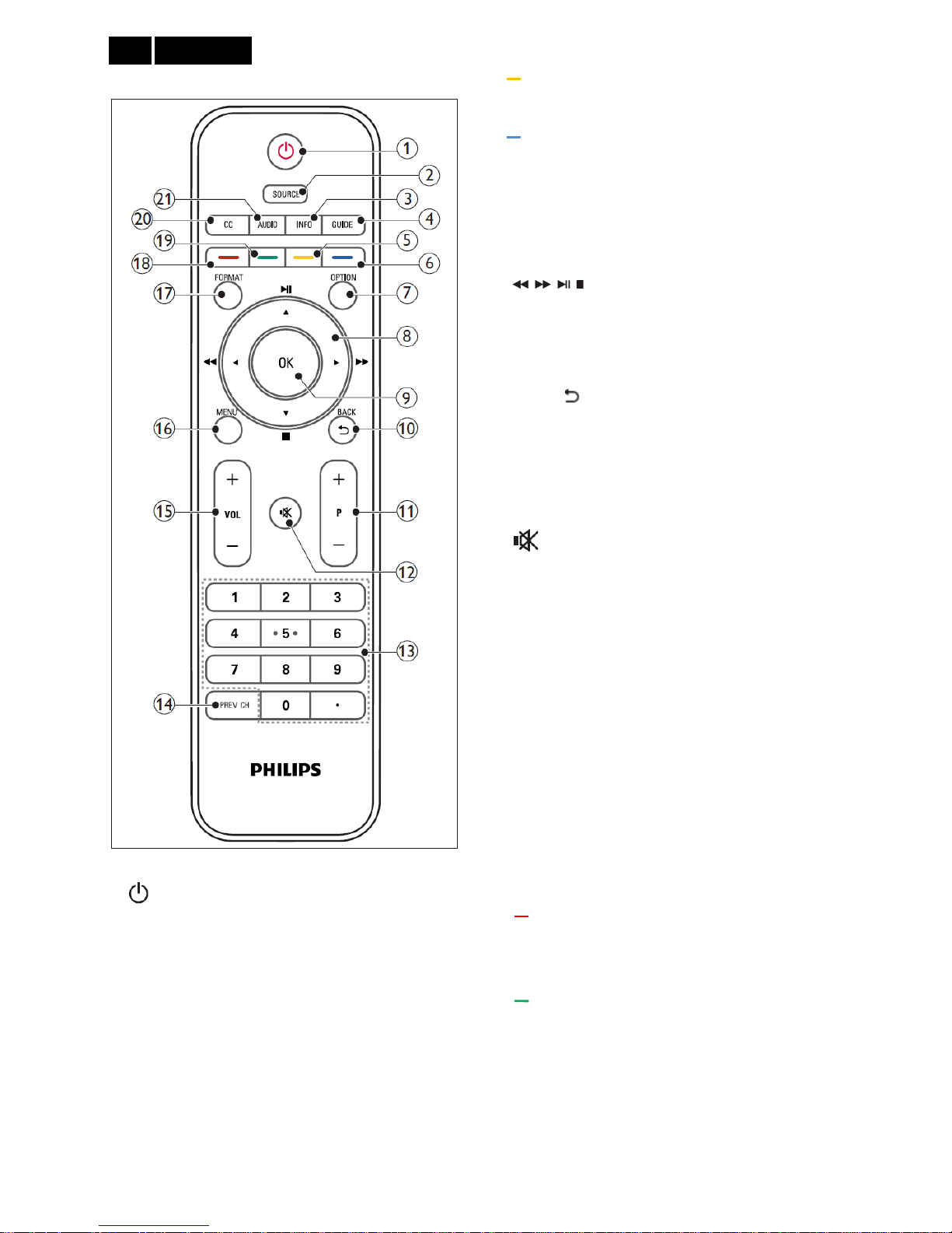
3.3 Remote Control
1.
(Standby-On)
Switch the monitor to standby if the monitor is on.
Switch the monitor on if the monitor is in standby.
2. SOURCE
Select connected devices.
3. INFO
Display or hide the information screen about the
selected channel.
4. GUIDE
Switch the Electronic Program Guide On or Off.
5.
(Yellow button)
Set the block channels in channel menu.
6.
(Blue button)
Delete the channel in channel menu.
7. OPTION
Press to display a list of options.
8. ▲ ▼ ◄ ► (Navigation buttons)
(No functions)
Navigate through the menus.
9. OK
Confirm an entry or selection.
10. BACK/
• Return to the previous screen.
• Return to the last viewed channel.
11. P +/-
Switch to the next or previous channel.
12.
(Mute)
Switch the sound On or Off.
13. 0-9 ( Numeric buttons )
Select a channel or setting.
14. PREV CH
• Return to the previous screen.
• Return to the last viewed channel.
15. VOL +/-
Increase or decrease the volume.
16. MENU
Press to open or close the on-screen menu.
17. FORMAT
Switch to different aspect ratio.
18.
(Red button)
• Set the favorite channel.
• Set the default setting for some options.
19.
(Green button)
Set the skip channels in channel menu.
20. CC
Switch the closed caption mode.
21. AUDIO
Switch stereo mode.
11
Meridian 4
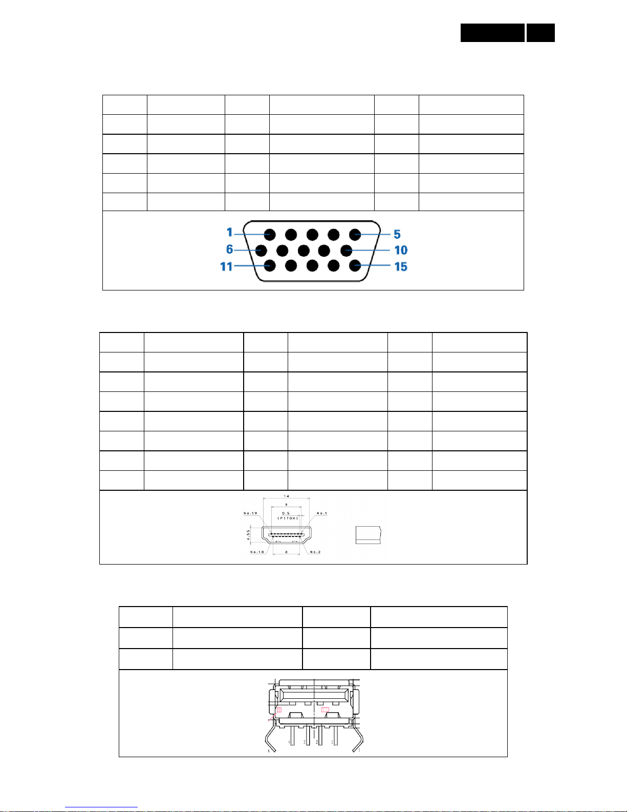
4. Input/ Output Specification
4.1 Input Signal Connector
Analog Connector
Pin No. Description Pin No. Description Pin No. Description
1 Red Video 6 Red Ground 11 RXD
2 Green Video 7 Green Ground 12 Serial Data for DDC
3 Blue Video 8 Blue Ground 13 H-Sync.
4 TXD 9 No Pin! 14 V-Sync.
5 Ground 10 Sync Ground 15 Serial Clock for DDC
HDMI Connector
Pin No. Description Pin No. Description Pin No. Description
1 TMDS Data2+ 8 TMDS Data0 shield 15 SCL
2 TMDS Data2 shield 9 TMDS Data0- 16 SDA
3 TDMS Data2- 10 TMDS Clock+ 17 DDC/CEC Ground
4 TMDS Data1+ 11 TMDS Clock Shield 18 +5V Power
5 TMDS Data1 shield 12 TMDS Clock- 19 Hot Plug Detect
6 TMDS Data1- 13 CEC
7 TMDS Data0+ 14 NC
USB
Pin No. Description Pin No. Description
1 VCC 3 DATA+
2 DATA- 4 GND
Meridian 4
12
4.2 Factory Preset Modes
Computer Formats
Resolution Refresh Rate
640x 480 60Hz
640 x 480 72Hz
640 x 480 75Hz
720 x 400 70Hz
800 x 600 56Hz
800 x 600 60Hz
800 x 600 72Hz
800 x 600 75Hz
1024 x 768 60Hz
1024 x 768 70Hz
1024 x 768 75Hz
1280 x 1024 60Hz
1440 x 900 60Hz
1680 x 1050 60Hz
1920 x 1080 60Hz
Video Formats:
Resolution Refresh Rate
480i 60Hz
480p 60Hz
576p 50Hz
720p 50Hz, 60Hz
1080i 50Hz, 60Hz
1080p 24Hz, 50Hz, 60Hz
4.3 Pixel Defect Policy
Philips strives to deliver the highest quality products.
We use some of the industry's most advanced
manufacturing processes and practice stringent quality
control. However, pixel or sub pixel defects on a flat
monitor panel are sometimes unavoidable. No
manufacturer can guarantee that all panels will be free
from pixel defects, but Philips guarantees that any
monitor with an unacceptable number of defects will be
repaired or replaced under warranty. This notice
explains the different types of pixel defects and defines
acceptable defect levels for each type. In order to
qualify for repair or replacement under warranty, the
number of pixel defects on a monitor panel must
exceed these acceptable levels. For example, no more
than 0.0004% of the sub pixels on a monitor may be
defective. Furthermore, Philips sets even higher quality
standards for certain types or combinations of pixel
defects that are more noticeable than others. This
policy is valid worldwide.
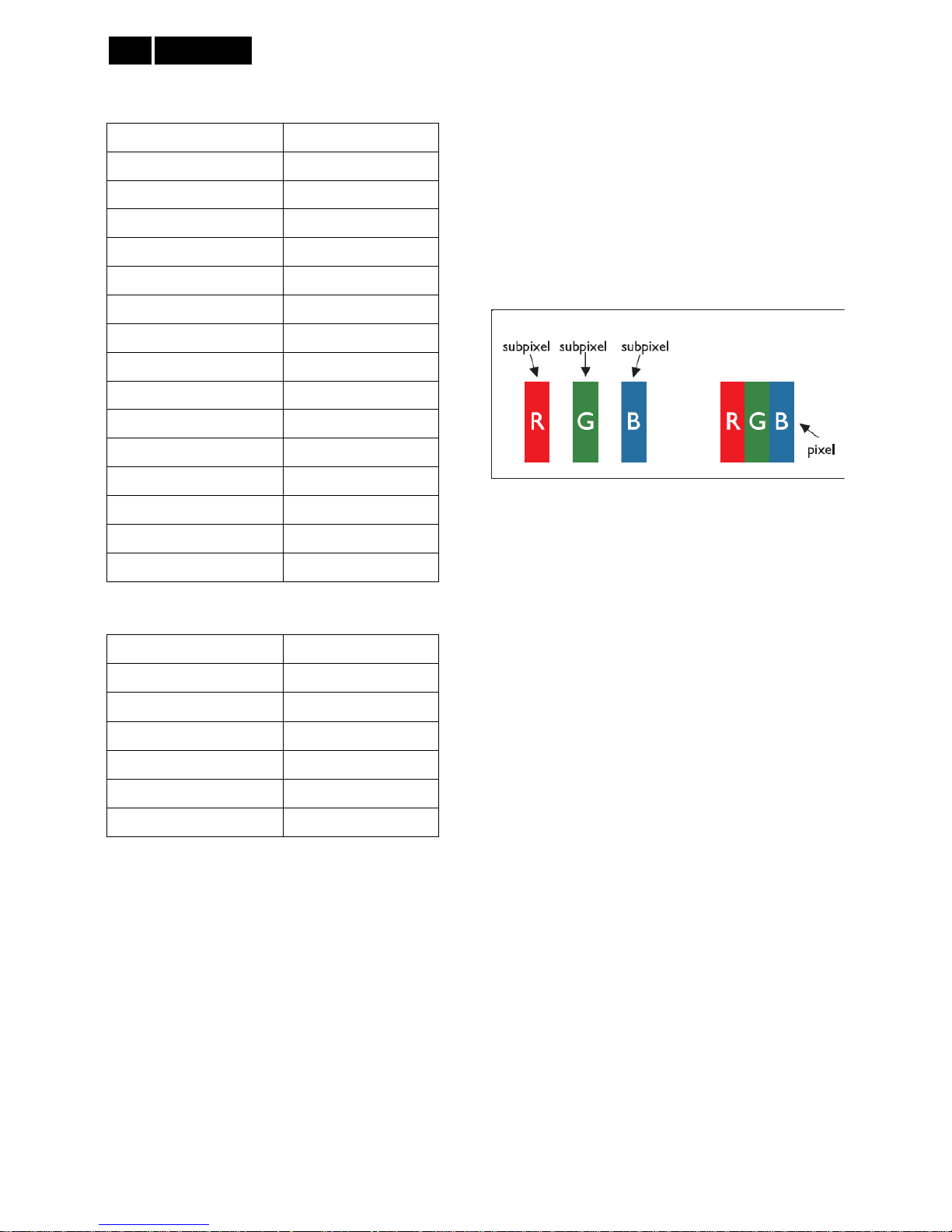
Pixels and Sub pixels
A pixel, or picture element, is composed of three sub
pixels in the primary colors of red, green and blue.
Many pixels together form an image. When all sub
pixels of a pixel are lit, the three colored sub pixels
together appear as a single white pixel. When all are
dark, the three colored sub pixels together appear as a
single black pixel. Other combinations of lit and dark
sub pixels appear as single pixels of other colors.
Types of Pixel Defects
Pixel and sub pixel defects appear on the screen in
different ways. There are two categories of pixel
defects and several types of sub pixel defects within
each category.
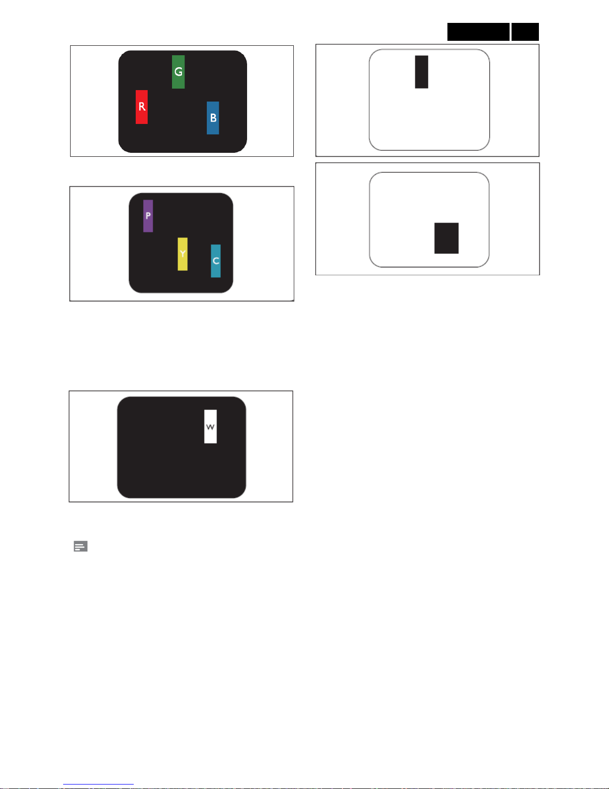
Bright Dot Defects: Bright dot defects appear as
pixels or sub pixels that are always lit or 'on'. That is, a
bright dot is a sub-pixel that stands out on the screen
when the monitor displays a dark pattern.
These are some types of bright dot defects:
13
Meridian 4
One lit red, green or blue sub pixel
Two adjacent lit sub pixels:
- Red + Blue = Purple
- Red + Green = Yellow
- Green + blue = Cyan (Light Blue)
Three adjacent lit sub pixels (one white pixel)
Note:
A red or blue bright dot must be more than 50 percent
brighter than neighboring dots while a green bright
dot is 30 percent brighter than neighboring dots.
Black Dot Defects: Black dot defects appear as pixels
or sub pixels that are always dark or 'off'. That is, a
dark dot is a sub-pixel that stands out on the screen
when the monitor displays a light pattern. There are
some types of black dot defects:
Proximity of Pixel Defects
Because pixel and sub pixels defects of the same type
that are near to one another may be more noticeable,
Philips also specifies tolerances for the proximity of
pixel defects.
Pixel Defect Tolerances
In order to qualify for repair or replacement due to pixel
defects during the warranty period, a Philips flat
monitor panel must have pixel or sub pixel defects
exceeding the tolerances listed in the following tables.

Meridian 4
14
BRIGHT DOT DEFECTS ACCEPTABLE LEVEL
MODEL 221TE4L / 231TE4L
1 lit subpixel 3
2 adjacent lit subpixels 1
3 adjacent lit subpixels (one white pixel) 0
Distance between two bright dot defects* >15mm
Total bright dot defects of all types 3
BLACK DOT DEFECTS ACCEPTABLE LEVEL
MODEL 221TE4L / 231TE4L
1 dark subpixel 5 or fewer
2 adjacent dark subpixels 2 or fewer
3 adjacent dark subpixels 0
Distance between two black dot defects* >15mm
Total black dot defects of all types 5 or fewer
TOTAL DOT DEFECTS ACCEPTABLE LEVEL
MODEL 221TE4L / 231TE4L
Total bright or black dot defects of all types 5 or fewer
Note:
1 or 2 adjacent sub pixel defects = 1 dot defect

15
Meridian 4
4.4 Failure Mode Of Panel
Failure description
Phenomenon
Vertical block defect
Vertical dim lines
Vertical lines defect
(Always bri
g
ht or dark)
Horizontal block de fect
Horizontal dim lines
Horizontal lines defect
(Always bri
g
ht or dark)
Has bri
g
ht or dark pixel
Polarizer has bubbles
Polarizer has bubbles
Foreign material inside
polarizer. It shows liner or
dot shape.
Concentric circle formed
Bottom back light of LCD is
brighter than normal
Back light un-uniformity
Backli
g
ht has foreign material.
Black or white color, liner or
circular type
Quick reference for failure mode of LCD panel
this pa
g
e presents problems that could be made by LCD panel.
It is not necessary to repair circuit board. Simply follow the mechanical
instruction on this manual to eliminate failure by replace LCD panel.
Meridian 4
16
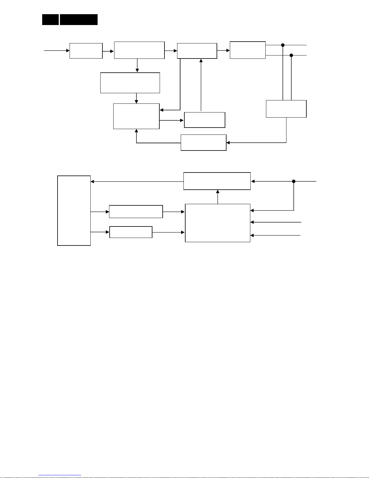
5. Block Diagram
5.1 Scaler Board
SXL SOC
NAND Flash
128Mx8 bit
TS S tream
Headphone
HDMI 1
SPEAKER
LVDS
Interface
CVBS+Audio IN(Share with Y+L/R)
USB
STA339BWTR
Speaker
Amplifier
VGA RGB +Audio IN
64Mx16_DDR3
Service Only
TC90517FG
4M bit
Serial
Flash
SPDIF Out
YP bP r + A ud io IN
IF
Nutune
FK1604
Ethernet
HDMI 2
L/R
17
Meridian 4
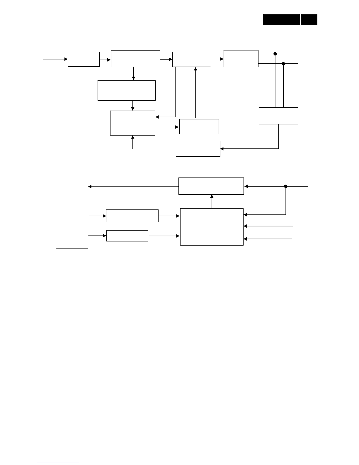
5.2 Power Board
221TE4L
EMI Filter
Start Resistor
(R906, R909, R911)
PWM Control
LD7576AGR
(IC901)
Transformer
AC Input
5.2V
Bridge Rectifier
and Filter
Feedback
Circuit
Rectifier
Diodes
Power Switch
(Q901)
Photocoupler
(IC902)
16V
ON/OFF
Feedback Circuit
LED Bar
Boost Circuit
16V
OVP Circuit
Setup-up Controller
RT8482GS
(IC904)
A
CTL
Meridian 4
18
231TE4L
EMI Filter
Start Resistor
(R905, R908, R909)
PWM Control
LD7750RGR
(IC901)
Transformer
AC Input
5V
Bridge Rectifier
and Filter
Feedback
Circuit
Rectifier
Diodes
Power Switch
(Q901)
Photocoupler
(IC902)
16V
ON/OFF
Feedback Circuit
LED Bar
Boost Circuit
16V
OVP Circuit
Setup-up Controller
OZ9998AGN
(IC801)
DIM
19
Meridian 4
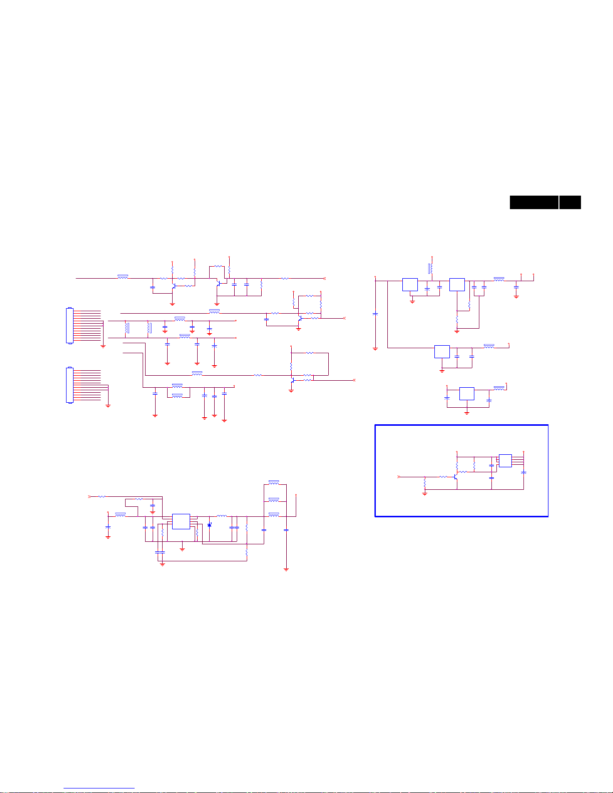
6. Schematic
6.1 Scaler Board (715G4786M01000005K, 715G5440M01000005K)
Remark: Parts position can be searched by using FIND function in PDF.
1 2
FB706
120R/3000mA
L0603
1 2
FB711
120R/3000mA
L0603
C739
NC
C0603
C723 22UF 6.3V
C0805
1 2
FB719 NC/120R/3000mA
L0603
C740
22UF 6.3V
C0805
5VSB 5V
GND
C722 100N 50V
C0603
12
FB741
0 OHM
1 2
FB713
120R/3000mA
L0603
C767
22UF 6.3V
12V_PRE
C706
10uF 6.3V
C0603
12
FB740
0R05 OHM
3.3V
C768
10U 16V
C0805
5V
HP_VCC_15
R713
22 OHM +-1% 1/10W
R0603
R709
100R
R0603
BRT_CTRL
5V 3.3V
+
C734
470UF 16V
Q706
PMBS3904
5VSB
R737
NC/4.7K 1/10W
PS_ON
3.3V
R736 NC/0R05 1/10W
3.3V
5VSB
+
C707
470UF 16V
+
C702
470UF 16V
+
C724
470UF 16V
R722
10K 1/10W
R725
3.6K 1%
+
C765
470UF 16V
1
2
3
4
5
6
7
8
9
10
11
12
13
CN701
NC/CONN
R728
9.1KOHM +-1% 1/10W
AUX_POWER_ON#
+
C727
470UF 16V
R802
4.7K 1/10W
R721
1K 1/10W
+
C731
100UF 16V
Q705
PMBS3904
1 2
FB728 NC/120R/3000mA
L0603
R720 100K 1/10W 5%
1 2FB705
120R/6000mA
L0805
R718
22K 1/10W
1 2FB709
120R/6000mA
L0805
1 2FB710
120R/6000mA
L0805
R719
NC/200K 1/10W
1 2FB712
NC/120R/6000mA
L0805
1 2
FB714
120R/6000mA
L0805
R739
1K 1/10W
1
2
3
4
5
6
7
8
9
10
11
12
13
CN704
CONN
BL_ON/OFF
C713
100N 50V
C0603
BL_ON/OFF_PR E
BRT_CTRL_PRE
12V_PRE
12V_PRE
24V_PRE
24V_PRE
PS_ON_PRE
5VSB_PRE
C751
0.47uF 16V
5VSB_PRE
5VSB_PRE
C701
100N 50V
5V
5VSB
C732
NC/4.7uF K 25V
2.0A--->DTV
1.08V-->Typ
R702
4.7K 1/10W
5V
R701
1K 1/10W
R704
NC/4.7K 1/10W
Q701
PMBS3904
C726
100N 50V
C0603
1 2
FB729
120R/3000mA
L0603
VIN3VOUT
2
GND
1
U704
S
1
S
2
S
3
G
4
D
8
D
7
D
6
D
5
Q704
AO4449 -7A/-30V
R703
4.7K 1/10W
C710
NC/10uF 6.3V
C714
100N 50V
C0603
SXL_PWRON
R710
10K 1/10W
R707
NC/4.7K 1/10W
R706
4.7K 1/10W
10x9mm
R711
NC/4.7K 1/ 10W
R708
4.7K 1/10W
R712
1K 1/10W
+
C716
330UF 35V
R738
1K 1/10W
Q702
PMBS3904
10x9mm
3VSB
R791
NC/4.7K 1/ 10W
R714
NC/4.7K 1/ 10W
R716
NC/4.7K 1/10W
R717
NC/4.7K 1/10W
BL_ON/OFF_PRE
Q703
NC/PMBS3904
BRT_CTRL_PRE
12V_PRE
12V_PRE
R715
NC/33R 1/ 16W 5%R0402
24V_PRE
24V_PRE
Vout = 0.8( 1+ Rtop/Rbo t)
PS_ON_PRE
5VSB_PRE
5VSB_PRE
Vout=0.8x (1+3.6K/9.1K) = 1.164V for G5684
BL_ON/OFF_PRE
5VSB_PRE
24V_PRE
PS_ON_PRE
5VSB_PRE
1 2
FB724
BEAD
R723 0R05 1/10W
Fs = 600K Hz
R724 10K 1/10W
1 2
FB718 120R/3000mA
L0603
VIN3VOUT
2
GND
1
U705
G1084-33TU3Uf
TO263G OI
BRT_CTRL_PRE
C729
1N 50V
C0402
C719
100N 50V
C0603
5V
1 2
FB715
120R/6000mA
L0805
+
C721
330UF 35V
C733
NC
C0603
1 2FB708
120R/6000mA
L0805
TO252
0.5A -->DTV
C720
100N 50V
C0603
C735
100N 16V
C0402
TO263
System power
C728
100N 16V
C0402
SYS_PW
Normal: High
Stand_By:
Low
3.3V,
3.3VSB,
2.5V,
1.5V
0.21A
C736
10U 16V
C0805
24V
12V
HP_VCC1V
HP_VCC_25
HP_VDDM
R726
27K 1/10W 1%
R0603
C744
NC
C0603
VIN3VOUT
2
GND
1
U702
G1084-33TU3Uf
TO263GOI
C745
1nF
C0603
COMP
1
GND
2
EN
3
IN4LX
5
LX
6
FREQ
7
FB
8
Therm al Pad
9
U706
G5684F11U
56A379-92
VOUT2VIN
3
ADJ
1
U703
G1084T43Uf
TO252GOI
R727
120K 1/10W 1%
R0603
C703
100N 50VC0603
1 2
D701
SK54B
SMB
L701
2.2uH 20mOHM 8A
L75X70-SMD
C737
100N 50V
C0603
C704 100N 50V
C0603
C738
22UF 6.3V
C0805
C705 22UF 6.3V
C0805
Power 1
20
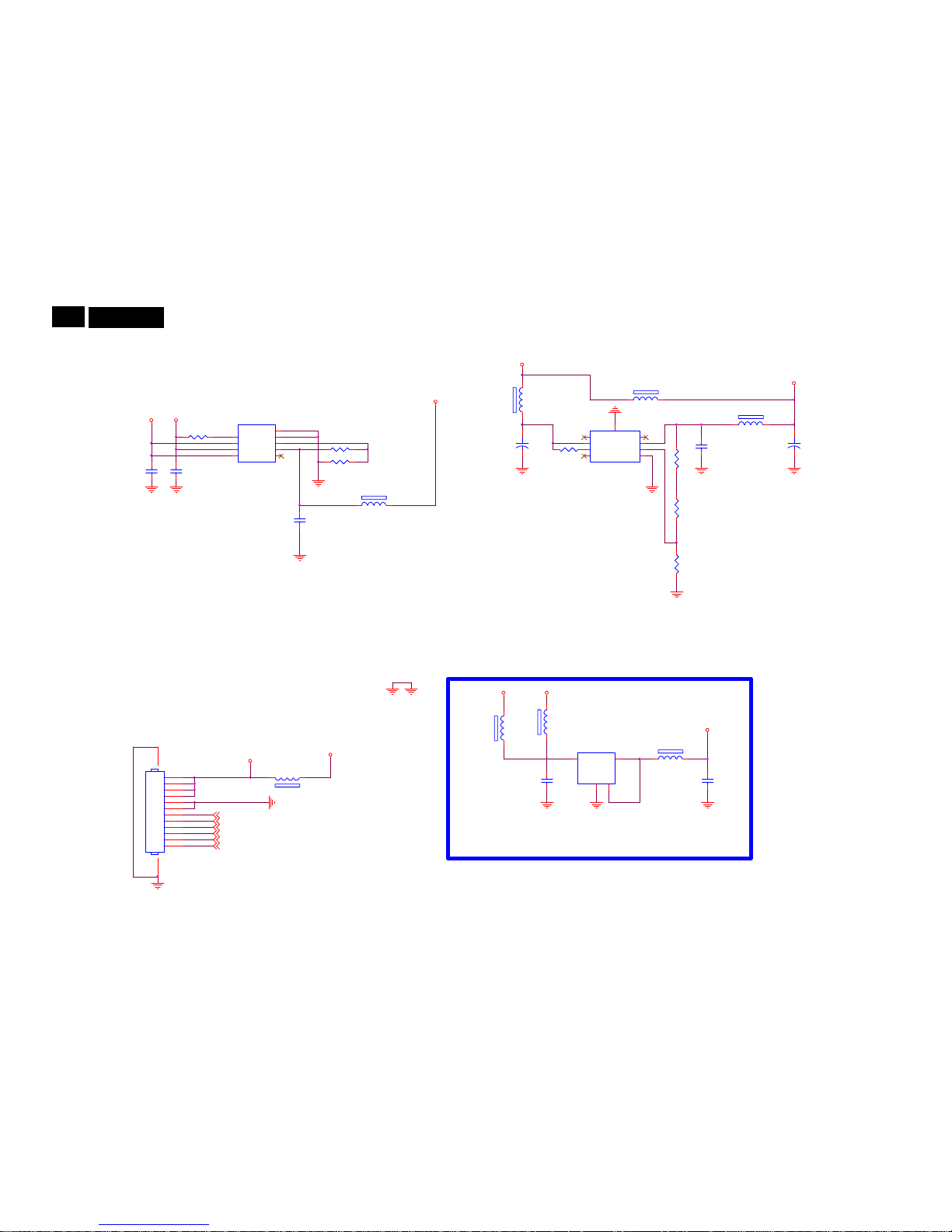
Meridian 4
Remark: Parts position can be searched by using FIND function in PDF.
1 2
FB725 220R/2000mA
202mA
1.1V
Vo=0.8(1+R752/R751)=1.116V
3.3V_TUNER
R731
910 OHM +-1% 1/10W
1 2
FB727
NC/120R /3000mA
C746
10uF 10V
1 2
FB726
120R/3000mA
VA_1.1
C747
10uF 10V
R732
360OHM 1/10W
5V_TUNER
1 2
FB720 NC/220R/2000mA
0.26 A
1 2
FB721 NC/220R/ 2000mA
5V
0.5((22K+20K+4K7)/4K7)=4.96V
5V_TUNER
SMD/0402
C748
1UF 10V
5VSB
MEMC_ SDA
MEMC_ SCL
MEMC5 V_SW
V105_SW
MEMC5 V
RESET_FRC
V105DLL_SW
1
2
3
4
5
6
7
8
9
10
11
12
13 14
CN702
NC/CONN
1 2
FB732
220R/2000m A
3.3V
+
C742
100UF 16V
R734
NC/22K 1/ 10W 1%
R735
NC/4K7 OH M 1/10W 1%
VIN3VOUT
2
GND14
4
U709
G903T63UF
C743
NC/100N 16V
C749
1uF 16V
R729
NC/20K 1/ 10W 1%
NC
1
EN
2
VIN
3
NC
4
GND
8
FB
7
VO
6
NC
5
TH1
9
U707
NC/SC4215HSETRT
C766
10U 16V
MEMC_ 5V1
3.3V_TUNER
3.3V
R758
NC/10K 1/10W
R730
10K+-5%1/16W
POK
1
VEN
2
VIN
3
VPP4NC
5
VO
6
ADJ
7
GND
8
E-Pad
9
U701
G9661
AGND
+
C741
NC/100UF 16V
EC63
1 2
FB731
NC/220R /2000mA
1 2
FB733
220R/2000mA
5V_TUNER
Power 2
 Loading...