

Page 1
User Manual
14PT6441/37
20PT6441/37
20PT6341/37
20PT5441/37
20PT6245/37
3141 095 20181
Model No.:
Serial No.:
Thank you for choosing Philips.
Need help fast?
Read your Quick Use Guide and/or
Owner's Manual first for quick tips
that make using your Philips product
more enjoyable.
If you have read your instructions
and still need assistance,
you may access our online help at
www.usasupport.philips.com
or call
1-888-PHILIPS (744-5477)
while with your product
(and Model / Serial number)
STOP
Page 2
PANEL
INDEX
Subject Panel No.
Antenna Basic Connection . . . . . . . . . . .1
Audio/Video Connections
AV Input Jacks . . . . . . . . . . . . . . . . . . . .4
Component Video Input Jacks . . . . . . . .7
Front (Side) Audio/Video Input Jacks . .5
Headphone Jack . . . . . . . . . . . . . . . . . .5
AV Output Jacks . . . . . . . . . . . . . . . . . .8
S-Video Input Jacks . . . . . . . . . . . . . . . .6
AutoLock™ Controls
Access Code . . . . . . . . . . . . . . . . . . . .19
Block All Channels . . . . . . . . . . . . . . .21
Block Channels . . . . . . . . . . . . . . . . . .20
Clear All Blocked Channels . . . . . . . . .21
Movie Ratings . . . . . . . . . . . . . . . . . . .22
Other Blocking Options . . . . . . . . . . .24
TV Ratings . . . . . . . . . . . . . . . . . . . . . .23
Understanding AutoLock™ . . . . . . . . .18
Automcatically Programming TV . . . . . .13
Subject Panel No.
AutoPicture™ Control . . . . . . . . . . . . .25
AutoSound™ Control . . . . . . . . . . . . . .25
Basic Remote Operation . . . . . . . . . . . . .3
Basic Television Operation . . . . . . . . . . .3
Cable Box Connection . . . . . . . . . . . . . .2
Channel Edit . . . . . . . . . . . . . . . . . . . . .14
Closed Caption Control . . . . . . . . . . . .25
Format Controls . . . . . . . . . . . . . . . . . .17
Language Controls . . . . . . . . . . . . . . . . .11
Limited Warranty . . . . . . . . . . . . . . . . .30
Picture Menu Controls . . . . . . . . . . . . .15
QuadraSurf™ . . . . . . . . . . . . . . . . . .27-28
Remote Batteries . . . . . . . . . . . . . . . . . .3
Remote Control Button Descriptions 9-10
Sleeptimer . . . . . . . . . . . . . . . . . . . . . . .25
Sound Menu Controls . . . . . . . . . . .14-15
Tuner Mode . . . . . . . . . . . . . . . . . . . . .16
Side 1
Side 2
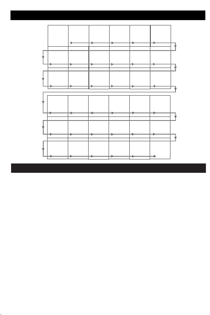
PANEL LAYOUT
Panel
Sequence
and
Panel Index
PANEL
3
MODEL
COVER
PANEL
REGISTRATION
INFORMATION
PANEL
4
5
SAFETY
INFO
PANEL
6
PANEL
1
PANEL
7
PANEL
2
PANEL
8
9
15
21
27
PANEL
10
PANEL
16
PANEL
22
PANEL
28
PANEL
11
PANEL
17
PANEL
23
PANEL
29
PANEL
PANEL
PANEL
PANEL
PANEL
12
PANEL
18
PANEL
24
PANEL
30
PANEL
PANEL
PANEL
PANEL
13
19
25
31
PANEL
14
PANEL
20
PANEL
26
PANEL
32
Page 3
Once your PHILIPS purchase is registered, you’re eligible to receive all
the privileges of owning a PHILIPS product. So complete and return the
Warranty Registration Card enclosed with your purchase at once. And
take advantage of these important benefits.
Return your Warranty Registration Card today to
ensure you receive all the benefits you’re entitled to.
Congratulations on your purchase, and welcome to the
“family!” To get the most from your PHILIPS product,
you must return your Warranty Registration Card within
10 days. So please mail it to us right now!
Know these
safetysymbols
t This “bolt of lightning” indicates uninsulated material within your unit may cause an electrical
hock. For the safety of everyone in your household, please do not remove product covering.
s The “exclamation point” calls attention to features for which you should read the enclosed
terature closely to prevent operating and maintenance problems.
WARNING: TO PREVENT FIRE OR SHOCK HAZARD, DO NOT EXPOSE THIS EQUIPMENT
TO RAIN OR MOISTURE.
CAUTION: To prevent electric shock, match wide blade of plug to wide slot, and fully insert.
ATTENTION: Pour éviter les chocs électriques, introduire la lame la plus large de la fiche dans la
borne correspondante de la prise et pousser jusqu’au fond.
CAUTION
RISK OF ELECTRIC SHOCK
DO NOT OPEN
CAUTION: TO REDUCE THE RISK OF ELECTRIC SHOCK, DO NOT
REMOVE COVER (OR BACK). NO USER-SERVICEABLE PARTS
INSIDE. REFER SERVICING TO QUALIFIED SERVICE PERSONNEL.
Warranty
Verification
Registering your product within 10 days confirms your right to maximum protection
under the terms and
conditions of your
PHILIPS warranty.
Owner
Confirmation
Your completed
Warranty Registration
Card serves as verification of ownership in the
event of product theft
or loss.
Model
Registration
Returning your
Warranty Registration
Card right away guarantees you’ll receive all
the information and
special offers which you
qualify for as the
owner of your model.
R
E
G
I
S
T
R
A
T
I
O
N
N
E
E
D
E
D
W
I
T
H
I
N
1
0
D
A
Y
S
Hurry!
Visit our World Wide Web Site at http://www.usasuport.philips.com
Page 4
IMPORTANT SAFETY INSTRUCTIONS
Read before operating equipment
Read these instructions.
Keep these instructions.
Heed all warnings.
Follow all instructions.
Do not use this apparatus near water.
Clean only with a dry cloth.
Do not block any of the ventilation openings. Install in accordance
with the manufacturers instructions.
Do not install near any heat sources such as radiators, heat registers,
stoves, or other apparatus (including amplifiers) that produce heat.
Do not defeat the safety purpose of the polarized or grounding-type
plug. A polarized plug has two blades with one wider than the other.
A grounding type plug has two blades and third grounding prong.
The wide blade or third prong are provided for your safety.When
the provided plug does not fit into your outlet, consult an electrician
for replacement of the obsolete outlet.
0. Protect the power cord from being walked on or pinched particularly
at plugs, convenience receptacles, and the point where they exit from
the apparatus.
1. Only use attachments/accessories specified by the manufacturer.
2. Use only with a cart, stand, tripod, bracket, or table
specified by the manufacturer, or sold with the appara
tus. When a cart is used, use caution when moving
the cart/apparatus combination to avoid injury from tip-over.
3. Unplug this apparatus during lightning storms or when unused for
long periods of time.
4. Refer all servicing to qualified service personnel. Servicing is required
when the apparatus has been damaged in any way, such as powersupply cord or plug is damaged, liquid has been spilled or objects
have fallen into apparatus, the apparatus has been exposed to rain
or moisture, does not operate normally, or has been dropped.
5. This product may contain lead and mercury. Disposal of these materi-
als may be regulated due to environmental considerations. For disposal or recycling information, please contact your local authorities or
the Electronic Industries Alliance: www.eiae.org
6. Damage Requiring Service - The appliance should be serv-
iced by qualified service personnel when:
A. The power supply cord or the plug has been damaged; or
B. Objects have fallen, or liquid has been spilled into the appli-
ance; or
C. The appliance has been exposed to rain; or
D. The appliance does not appear to operate normally or
exhibits a marked change in performance; or
E. The appliance has been dropped, or the enclosure damaged.
17. Tilt/Stability - All televisions must comply with recommended
international global safety standards for tilt and stability properties of
its cabinet design.
• Do not compromise these design standards by applying excessive
pull force to the front, or top, of the cabinet which could ultimately
overturn the product.
• Also, do not endanger yourself, or children, by placing electronic
equipment/toys on the top of the cabinet. Such items could unsuspectingly fall from the top of the set and cause product damage
and/or personal injury.
18. Wall or Ceiling Mounting - The appliance should be
mounted to a wall or ceiling only as recommended by the manufacturer.
19. Power Lines - An outdoor antenna should be located away from
power lines.
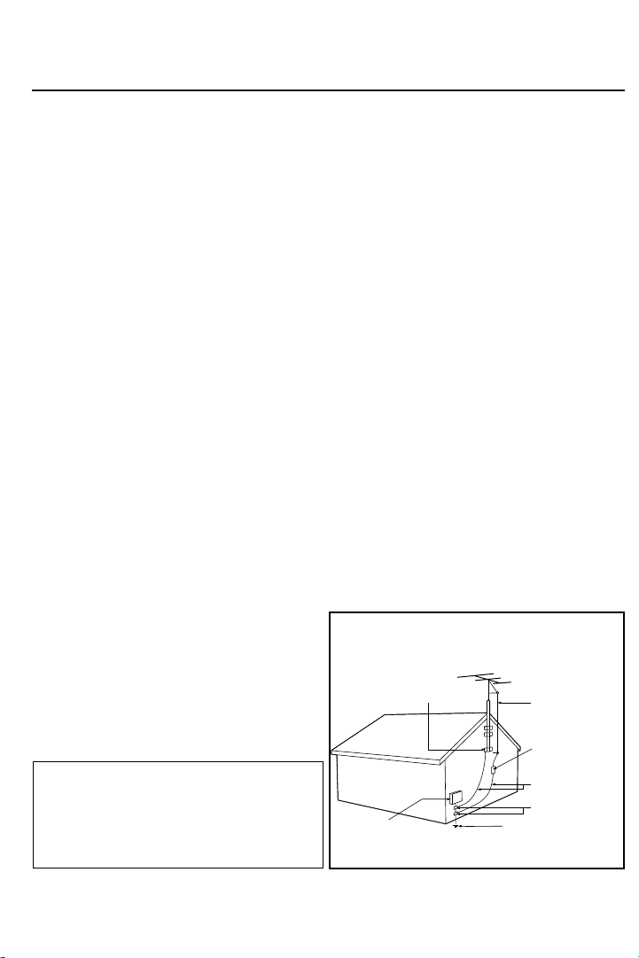
20. Outdoor Antenna Grounding - If an outside antenna is
connected to the receiver, be sure the antenna system is grounded
so as to provide some protection against voltage surges and built up
static charges.
Section 810 of the National Electric Code, ANSI/NFPA No. 70-1984,
provides information with respect to proper grounding of the mast
and supporting structure, grounding of the lead-in wire to an antenna discharge unit, size of grounding connectors, location of antennadischarge unit, connection to grounding electrodes, and requirements
for the grounding electrode. See Figure below.
21. Object and Liquid Entry - Care should be taken so that
objects do not fall and liquids are not spilled into the enclosure
through openings.comply with recommended international global safety standards for tilt and stability properties of its cabinet design.
22. Battery Usage CAUTION - To prevent battery leakage that
may result in bodily injury, property damage, or damage to the unit:
• Install all batteries correctly, with + and - aligned as marked on
the unit.
• Do not mix batteries (old and new or carbon and alkaline, etc.).
• Remove batteries when the unit is not used for a long time.
Note to the CATV system installer: This
eminder is provided to call the CATV system
nstaller's attention to Article 820-40 of the NEC
hat provides guidelines for proper grounding and, in
particular, specifies that the cable ground shall be
onnected to the grounding system of the building,
s close to the point of cable entry as practical.
Example of Antenna Grounding
as per NEC - National Electric Code
ELECTRIC SERVICE EQUIPMENT
GROUND CLAMP
ANTENNA LEAD IN WIRE
ANTENNA DISCHARGE UNIT
(NEC SECTION 810-20)
GROUNDING CONDUCTORS
(NEC SECTION 810-21)
GROUND CLAMPS
POWER SERVICE GROUNDING ELECTRODE SYSTEM
(NEC ART 250, PART H)
Page 5
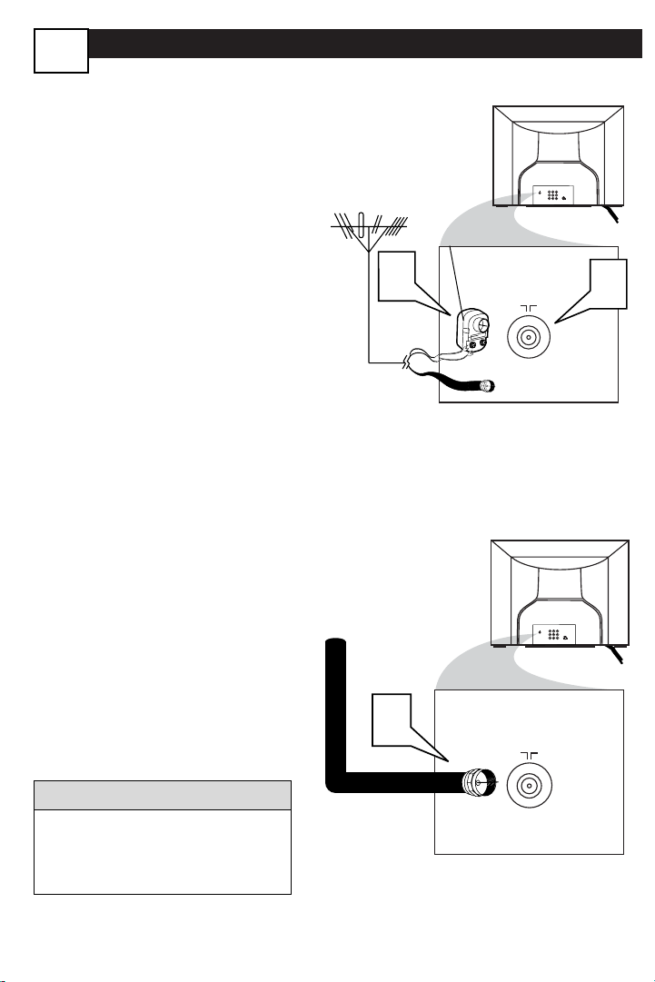
BASIC ANTENNA AND CABLE CONNECTIONS
Y
our home’s signal input might come from
a single (75 ohm) round cable, a
onverter Box, or from an antenna. In either
ase the connection to the TV is very easy.
1
If your Cable TV signal or
Antenna signal is a round cable
(75 ohm) then you're ready to connect to the TV.
If your antenna has flat twinlead wire (300 ohm), you first
need to attach the antenna wires to
the screws on a 300 to 75 ohm
adapter.
If you have a Cable Converter
Box: Connect the Cable TV signal
to the Cable Signal IN(put) plug on
the Converter.
2
Connect the Cable TV cable or
Antenna cable (or 300 to 75 ohm
adapter) to the 75Ω plug on the TV.
If you have a Cable Converter
Box: Connect the OUT(put) plug
from the Converter to the 75Ω plug
on the TV.
After using the AutoProgram
Control, press the CH + and – buttons to scroll through all the channels
stored in the television’s memory.
HELPFUL HINT
Back of TV
Cable signal
coming from
Cable Company
Jack Panel Back of TV
75
1
2
75‰
L
R
S-VIDEO
VIDEO
AUDIO
CVIAV out
Y
Pb
Pr
AV in
Antenna Connection
300 to 75Ω
Adapter
Combination
VHF/UHF Antenna
(Outdoor or Indoor)
Twin Lead
Wire
Round Cable
75Ω
Back of TV
Direct Cable Connection
75Ω Round
Coaxial Cable
1
1
75‰
75
AV in
CVIAV out
VIDEO
Y
L
S-VIDEO
Pb
AUDIO
R
Pr
Page 6
L
VIDEO
S-VIDEO
CVI
Y
Pb
Pr
AUDIO
TO
TV/VCR
CABLE
IN
IR
USB
DVD-D OUT
AUDIO IN
SPDIF
VIDEO
IN OUT
S-VIDEO
R L
AUDIO OUT
TV
PASSCARD
Y Pb Pr
OPTICAL
SPDIF
4
6
24
5
75‰
L
R
S-VIDEO
VIDEO
AUDIO
CVIAV out
Y
Pb
Pr
AV in
AV In
AV Out
R
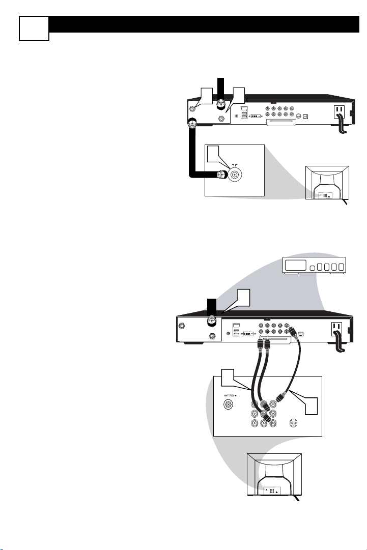
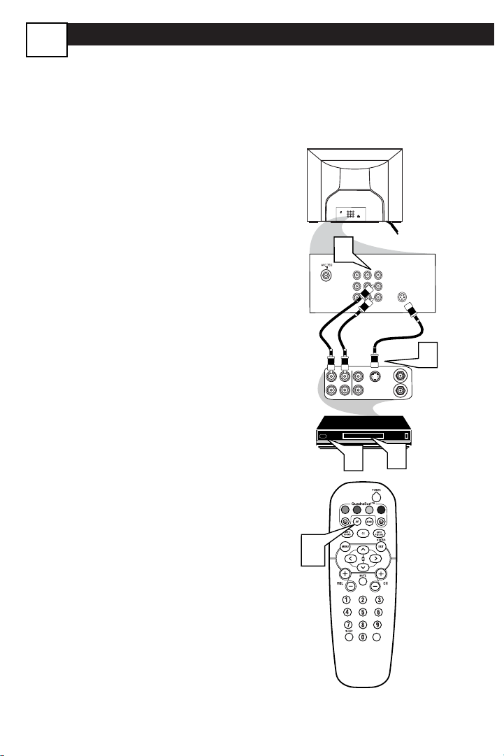
CABLE
BOX CONNECTIONS
2
I
f you cable signal uses a cable box or
decoder, follow the easy steps below to
omplete the connection.
Cable Box (w/RF In/Outputs):
his connection will be mono.
1
Connect the Cable Company
supplied cable to
the signal IN(put)
plug on the back of the Cable Box.
2
Using a separate round coaxial cable,
connect one end to the
OUT(put)
(TO TV) plug on the back of the
Cable Box.
3
Connect the other end of the
round coaxial cable to the 75Ω
input on the back of the television.
Screw it down finger tight.
NOTE: If applicable, set the OUTPUT
HANNEL SWITCH on the back of the
able box to CH 3 or 4. Tune the TV to
he same channel and change channels at
he cable box. In some cases, the cable box
ill automatically tune to either channel 3
r 4, change channels until the picture
ppears.
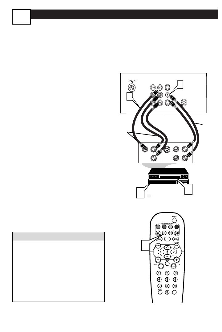
Cable Box (w/Audio/Video Outputs):
his connection will supply Stereo sound.
4
Connect the Cable Company
supplied cable to
the cable signal
IN(put) plug on the back of the
Cable Box.
5
Using a RCA type Video Cable, connect one end of the cable to the
Video (or ANT, your cable box may be
labeled differently) Out jack on the
cable box and the other end to the
AV1 Video Input on the TV.
6
Connect one end of the Audio Left
and Right Cable to the left and
right Audio Out L & R jacks on
the cable box. Connect the other
end to the AV In Audio L & R Input
jacks on the TV.
NOTE: Use the AV button on the TV
emote control to tune to the AV channel
or the cable box signal. Once tuned,
hange channels at the cable box, not the
elevision.
Jack Panel Back of Cable Box
Cable Signal IN from the
Cable Company
Round 75Ω
Coaxial Cable
Jack Panel Back of TV
Cable Signal IN
from the Cable
Company
Cable Box with A/V Outputs
Jack Panel Back of TV
Audio Cables
L (White) & R (Red)
Video Cable
(Yellow)
Cable Box (w/RF In/Outputs):
Cable Box (w/Audio/Video Outputs):
2
TO
TV/VCR
1
CABLE
IR
IN
3
75
VIDEO
AUDIO IN
SPDIF
IN OUT
R L
DVD-D OUT
Y Pb Pr
AUDIO OUT
USB
TV
PASSCARD
S-VIDEO
OPTICAL
SPDIF
AV in
CVIAV out
75‰
VIDEO
Y
L
S-VIDEO
Pb
AUDIO
R
Pr
Page 7
BASIC TV AND REMOTE CONTROL OPERATION
3
1
Press the POWER button
to turn the TV ON.
Note: You can also press any
button on the front of the TV
to turn the TV ON.
2
Press the VOLUME + button
to increase the sound level, or the
VOLUME – button to lower the
sound level.
Pressing both buttons at the
same time will display the on-
screen menu. Once in the menu,
use these buttons to make adjustments or selections.
3
Press the CHANNEL UP + or
DOWN – button to select TV
channels.
4
Point the remote control
toward the remote sensor window on the TV when operating
the TV with the remote.
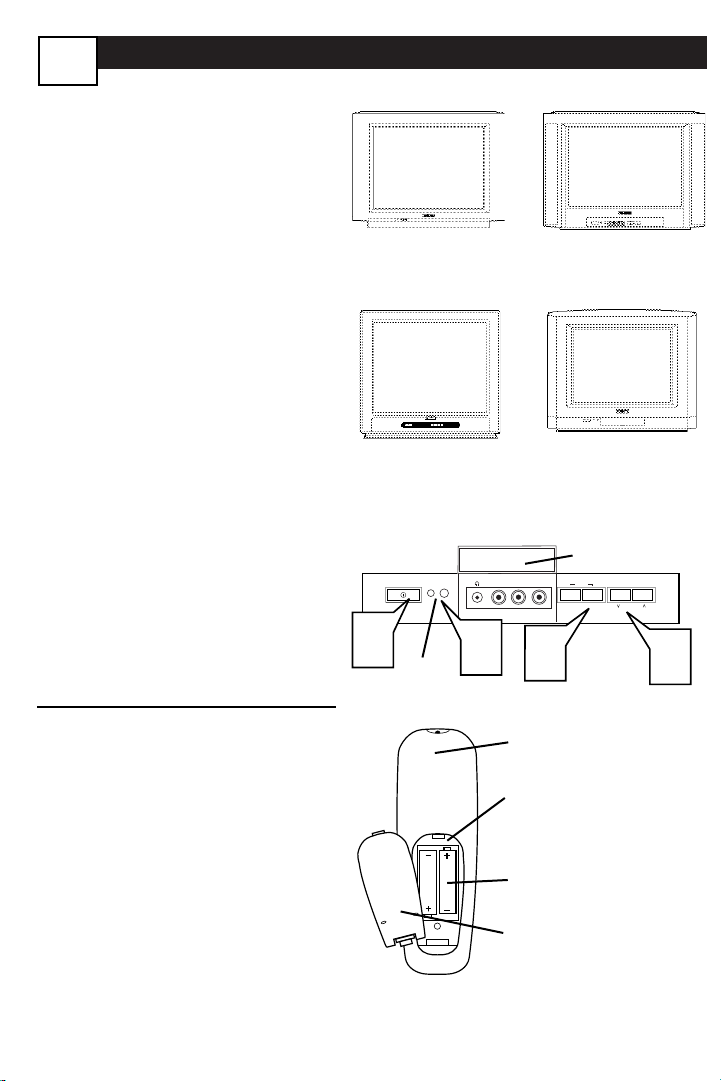
REMOTE CONTROL
T
o load the supplied batteries
into the remote:
1. Remove the battery compartment lid on the back of the
emote.
2. Place the batteries (2-AA) in
he remote. Be sure the (+) and (-
ends of the batteries line up cor-
ectly (inside of case is marked.)
3. Reattach the battery lid.
Battery Compartment
2-AA Batteries
Battery Lid
Back of Remote
20PT5441/37
Controls located
on front of set.
14PT6441/37
Contols under door
on front of set.
20PT6441/37
Controls located on
front and top of set.
– VOLUME +
CHANNEL
MENU
AUDIO
VIDEO
L
R
1
2
3
4
Door Cover
Remote
Sensor Window
20PT6341/37
20PT6245/37
Controls located on
front of set.
Example of Controls, 14PT6441/37 shown.
Page 8
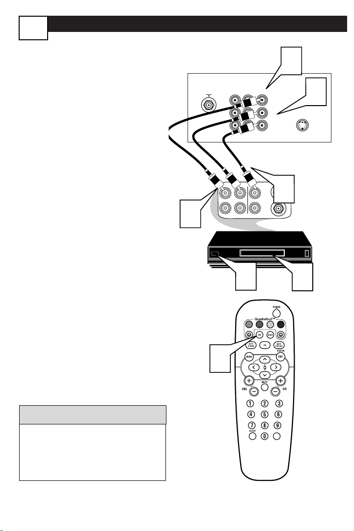
AV (AUDIO/VIDEO) INPUT CONNECTION
4
T
he TV’s audio/video input jacks are for
direct picture and sound connections
etween the TV and a VCR (or similar device)
hat has audio/video output jacks. Follow the
asy steps below to connect an accessory
evice to the AV In Input Jacks located on the
ack of the TV.
1
Connect the VIDEO (yellow)
cable to the VIDEO AV In jack on
the back of the TV.
2
Connect the AUDIO (red and
white) cables to the AUDIO (left
and right) AV In jacks on the rear of
the TV.
3
Connect the VIDEO (yellow)
cable to the VIDEO OUT jack on
the back of the VCR.
4
Connect the AUDIO (red and
white) cables to the AUDIO (left
and right) OUT jacks on the rear of
the VCR.
5
Turn the VCR (accessory device)
and the TV ON.
6
Press the AV button on the
remote control to select the AV
channel. AV will appear in the upper
left corner on the TV screen.
7
With the VCR (or accessory device)
ON and a prerecorded tape (CD,
DVD, etc.) inserted, press the
PLAY
button to view the tape
on the television.
All the AV channels can be selected by
pressing the Channel + or – buttons.
The AV channels can also be added to
the QuadraSurf™ buttons for quick
access.
HELPFUL HINT
Video Cable
(Yellow)
Audio Cables
(Red & White)
Back of TV
Back of Typical VCR
VCR with
Audio/Video Outputs
75
222
3
6
AV Out
CVI
Y
Pb
Pr
LR
AUDIO
IN
5
VOL
AV In
VIDEO
L
AUDIO
R
ANTENNA
OUTOUT
IN
4
VIDEO
ANTENNA
OUT
IN
1
2
S-VIDEO
7
Page 9
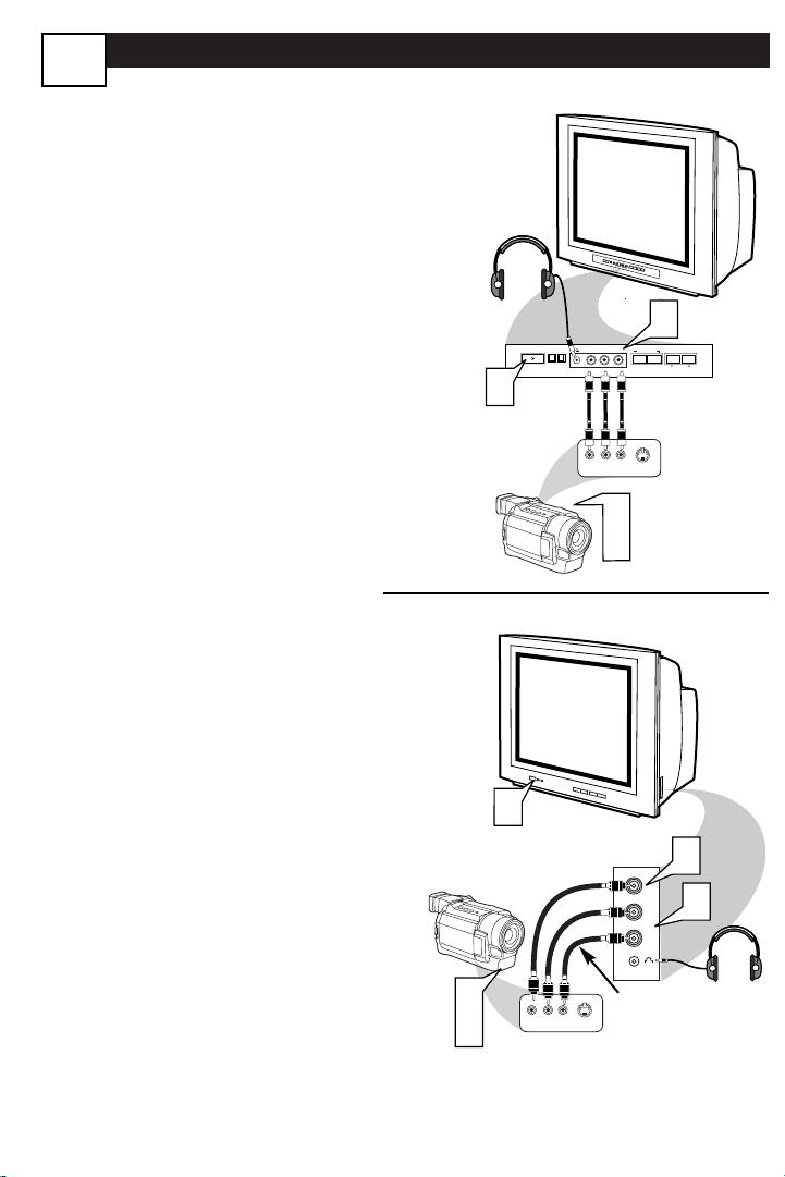
FRONT AND SIDE AV CONNECTIONS
5
A
udio and Video Front (or Side) Inputs
are available for a quick connection of a
CR, to playback video from a camera, or
ttach a gaming device. Use the AV button
n the remote control to tune these inputs.
1
Connect the video (yellow)
cable from the Video output on
the Camera (or accessory device)
to the Video (yellow) Input located
on the SIDE (or FRONT) of the
TV.
2
For Stereo Devices: Connect the
audio cable (red and white) from
the Audio Left and Right Outputs
on the Camera to the Audio In
(white) jack on the SIDE (or
FRONT) of the television.
For Mono Devices: Connect one
end of the audio cable from the
Audio Out jack on the device to
the Audio In (white) jack on the
SIDE (or FRONT) of the television.
3
Turn the TV and the accessory
device ON.
4
Press the AV button on the
remote control to tune the TV to
the side (or front) input jacks. “AV”
will appear on the TV screen.
5
Press the PLAY button on
the accessory device to view playback, or to access the accessory
device (camera, gaming unit, etc.).
Side AV Inputs:
Front AV Inputs:
14PT6441/37
20PT5441/37
20PT6341/37
20PT6441/37
20PT6245/37
Audio
Cables
Video
Cable
Front Jack panel of TV
Side Jack
panel of TV
Audio
Cables
Video
Cable
Jack Panel of Accessory Device
Optional
Headphones
Jack Panel of
Accessory
Device
Optional
Headphones
3
Front
3
Front
I
N
S
V
T
I
A
D
L
E
O
L
L
A
U
D
I
O
R
–
V
O
L
U
M
E
VIDEO L R
AUDIO
VIDEOAUDIO
LEFT RIGHT
3
5
/
M
E
N
U
+
C
H
A
N
N
E
L
INSTALL/MENU
– VOLUME +
S-VIDEO
VIDEO
L
AUDIO
R
– VOLUME +
2
CHANNEL
CHANNEL
1
2
3
5
LEFT RIGHT
VIDEOAUDIO
S-VIDEO
Page 10
S-VIDEO (S-VHS) INPUT CONNECTIONS
T
he S(uper)-Video connection on the rear
of the TV can provide you with better pic-
ure detail and clarity for the playback of
ccessory sources such as DBS (digital broad-
ast satellite), DVD (digital video discs), video
ames, and S-VHS VCR (video cassette
ecorder) tapes than the normal antenna pic-
ure connections.
NOTE: The accessory device must have an
-VIDEO OUT(put) jack in order for you to
omplete the connection on this page.
1
Connect one end of the SVIDEO CABLE to the S-VIDEO
jack on the back of the TV. Then
connect one end the AUDIO (red
and white) CABLES to the AV In
AUDIO L and R (left and right) jacks
on the rear of the TV.
2
Connect other end of the SVIDEO CABLE to the S-VHS (S-
Video) OUT jack on the back of the
VCR. Then connect the other ends
of the AUDIO (red and white)
CABLES to the AUDIO (left and
right) OUT jacks on the rear of the
VCR.
3
Turn the VCR and the TV ON.
4
Press the AV button or the
CH + or CH – buttons on the
remote to scroll the channels until
SVHS appears in the upper left corner of the TV screen.
5
Now your ready to place a prerecorded video tape in the VCR and
press the PLAY button
.
VCR or External
Accessory Device
(with S-Video
Output)
Audio Cables
(Red & White)
S-Video
Cable
Back of TV
6
NOTE: When using additional accessories, only one
external source will be audible, as there is only one
set of sound inputs. Component Video (CVI) input
will dominate over all other inputs, including S-Video
(S-VHS) and AV. When S-Video (S-VHS) is used, it
will dominate over the AV input.
AV in
CVIAV out
75‰
VIDEO
Y
L
S-VIDEO
Pb
AUDIO
R
Pr
1
CVI
AV In
VIDEO
Y
L
Pb
AUDIO
S-VIDEO
R
Pr
2
ANTENNA
IN
ANTENNA
OUT
5
4
OUTOUT
S-VHS OUT
VIDEO
LR
AUDIO
IN
IN
3
VOL
Page 11
COMPONENT VIDEO (CVI) INPUT CONNECTIONS
C
omponent Video inputs provide for the
highest possible color and picture resolu-
on in the playback of digital signal source
material, such as with DVD players. The
olor difference signals (Pb, Pr) and the
uminance (Y) signal are connected and
eceived separately, which allows for
mproved color bandwidth information (not
ossible when using composite video or S-
Video connections).
1
Connect the Component (Y, Pb,
Pr) Video OUT jacks from the
DVD player (or similar device) to the
(Y, Pb, Pr) in(put) jack on the TV.
When using the Component Video
Inputs, it is best not to connect a
signal to the AV in Video Jack.
2
Connect the red and white
AUDIO CABLES to the Audio
(left and right) output jacks on the
rear of the accessory device to the
Audio (L and R) AV In Input Jacks
on the TV.
3
Turn the TV and the DVD (or
digital accessory device) ON.
4
Press the AV button or the
CH + or CH – buttons to scroll
the available channels until CVI
appears in the upper left corner of
the TV screen.
5
Insert a DVD disc into the DVD
player and press the PLAY
button on the DVD Player.
The description for the component video con-
nectors may differ depending on the DVD player
or accessory digital source equipment used (for
example, Y, Pb, Pr; Y, B-Y, R-Y; Y, Cr, Cb).
Although abbreviations and terms may vary, the
letters b and r stand for the blue and red color
component signal connectors, and Y indicates
the luminance signal. Refer to your DVD or dig-
ital accessory owner’s manual for definitions and
connection details.
HELPFUL HINT
Component
Video Cables
(Green, Blue,
Red)
Audio
Cables
(Red &
White)
Accessory Device
Equipped with
Component Video
Outputs
Back of TV
7
NOTE: When using additional accessories, only one
external source will be audible, as there is only one
set of sound inputs. Component Video (CVI) input
will dominate over all other inputs, including S-Video
(S-VHS) and AV. When S-Video (S-VHS) is used, it
will dominate over the AV input.
1
Y
3
CVI
COMP VIDEO
Pb
Pr
Y
Pb
Pr
AV In
S-VIDEO
OUT
VIDEO
L
AUDIO
R
VIDEO
2
S-VIDEO
AUDIO
OUT
OUT
R
L
5
4
VOL
Page 12

8
T
he Audio/Video Output jacks are great for
recording with a VCR or used to connect
n external audio system for better sound
eproduction.
AUDIO SYSTEM CONNECTION:
1
Connect one end of the R(ight)
and L(eft) AUDIO jacks on the
TV to the R and L audio input jacks
on your amplifier or sound system.
Set the audio system’s volume to a
normal listening level.
2
Turn the TV and audio system
ON. To adjust the volume on the
audio system, you will need to
change the volume at the external
audio system, not the television.
ECOND VCR CONNECTION:
NOTE: Refer to panel number 4 for the
roper hookup of the first VCR. Follow
he instructions on how to tune to the
AV1 channel to view a pre-recorded
ape.
The following steps allow you to
onnect a second VCR to record the
rogram while your watching it.
1
Connect one end of the yellow
Video Cable to the AV Out
VIDEO plug. Connect the other end
to the VIDEO IN plug on the second
VCR.
2
Connect one end of the red and
white Audio cable from the AV
Out AUDIO L and R plugs on the
TV to the AUDIO IN plugs on the
VCR.
3
Turn the Second VCR ON,
insert a VHS tape and it’s ready to
record what’s being viewed on the
TV screen.
Back of TV
Audio Cables
(Red and White)
Back of TV
Audio Cables
1st VCR
(refer to panel 4 for
proper connection)
Video
Cable
2nd VCR with Audio and
Video Input Jacks
SECOND VCR CONNECTION:
AUDIO SYSTEM CONNECTION:
1
AV Out
CVI
AV In
VIDEO
Y
L
Pb
AUDIO
R
Pr
1
R
L
T
U
P
N
I
V
T
/
X
U
A
T
U
P
N
I
O
N
O
H
P
2
1
ANTENNA
IN
ANTENNA
OUT
OUT OUT
VIDEO
IN
AV Out
RL
AUDIO
IN
CVI
AV In
VIDEO
Y
L
Pb
AUDIO
R
Pr
2
S-VIDEO
AUDIO
IN
3
S-VIDEO
ANTENNA
OUTOUT
IN
VIDEO
LR
ANTENNA
OUT
IN
Page 13

REMOTE C
ONTROL BUTTON DESCRIPTIONS
9
QUADRASURF Buttons
Red, Green, Yellow, Blue) Allows you to
tore and surf up to 10 channels you choose
or each colored button.
AV Button
ress to select an accessory signal input from
he front AV Inputs.
SMILEY Button
ress to add channels to the “QuadraSurf”
sts. Works with all colored buttons.
AUTO SOUND Button
ress repeatedly to choose from different fac-
ory pre-defined sound settings. Choose from
ersonal (how you set the Sound Menu
ptions), Voice (for programming with speak-
ng only), Music (for musical type programs
uch as concerts), or Theatre (used when
watching movies).
MENU Button
ress to display the on-screen menu. Also can
e used to back out of the on-screen menu
ntil it disappears from the TV’s screen.
CC Button
ress to activate the Closed Captioning
ptions. Repeatedly pressing the CC button
will scroll the available options on the TV
creen.
VOL(ume) + or - Buttons
ress the VOL + button to increase the TV’s
ound level. Press the VOL – button to
ecrease the TV’s sound level.
MUTE Button
ress the mute button to eliminate the sound
eing heard from the TV. “MUTE” will be dislayed on the TV’s screen. Press again to
estore the TV’s volume to it’s previous level.
SLEEP Button
ress the Sleep button to set the TV to auto-
matically turn itself off after a set period of
me. Press repeatedly to select 15, 30, 45, 60,
0, 120, 180, or 240 minutes.
VOL
Page 14

REMOTE CONTROL BUTTON DESCRIPTIONS
10
POWER Button
Press to turn the TV on or off.
A/CH Button (Alternate Channel)
Press to toggle between the last viewed channel
and the channel presently being viewed.
FROWNIE Button
Allows you to delete channels from the “Quadra
Surf” lists for the colored buttons. Works with all
colored buttons.
AUTO PICTURE Button
Press repeatedly to choose from 5 different factory predefined picture settings. Choose from
Personal (how you set the Picture Menu
Adjustment controls), Movies (for movies), Sports
(for any sporting event), Weak Signal (used when
the signal being received is not great), or
Multimedia (for video games).
STATUS/EXIT Button
Press to display the current channel number. If the
on-screen menu is displayed, press the Status/Exit
button of remove it from the TV’s screen.
3, 4, 1, and 2 Buttons
Press to navigate, select, and adjust controls within
the on-screen menu. Also use the CURSOR 3 or
CURSOR 4 to activate or deactivate the
EXPAND 4:3 screen formatting control.
CH(annel) + or CH(annel)- Buttons
Press to select channels in ascending or descending
order.
NUMBERED (0-9) Buttons
Press the numbered buttons to select TV channels
or to enter certain values within the on-screen
menu. For single channel entries, press the numbered button for the channel you desire. The TV
will pause for a second or two before changing to
the chosen channel.
NOTE:
This button is dedicated to TIMER features within
certain TV models. This TV does not contain these
TIMER features, therefore the button will have no
functionality when pressed.
VOL
Page 15

F
or French and Spanish speaking TV
owners an onscreen LANGUAGE option
present. With the LANGUAGE control
ou can set the TV’s on-screen menu to be
hown in English, French, or Spanish.
1
Press the MENU button on
the remote control to show the
on-screen menu.
2
Press the CURSOR UP 3 or
DOWN 4 buttons to scroll
though the on-screen menu until
the word INSTALL is highlighted.
3
Press the CURSOR RIGHT 2
button to display the INSTALL
menu features.
4
Press the CURSOR UP 3 or
DOWN 4 buttons to scroll
through the Install features until
the word LANGUAGE is highlighted.
5
Press the CURSOR RIGHT 2
button repeatedly to select
English, Francais (French), or
Espanol (Spanish).
6
When finished, press the
STATUS/EXIT button to
remove the menu from the TV’s
screen.
HOW TO USE THE LANGUAGE CONTROL
11
The Language contol only makes the
TV’s on-screen MENU items appear
n English, Spanish, or French text.
t does not change the other onscreen text features such as Closed
Caption (CC) TV shows.
HELPFUL HINT
Main
Picture
Sound
Features
Install
Brightness
Color
Picture
Sharpness
Tint
More...
Main
Picture
Sound
Features
Install
Language
Tuner Mode
Auto Program
Channel Edit
1
2
4
2
4
VOL
6
3
5
Install
Language
Tuner Mode
Auto Program
Channel Edit
Instalar
Idioma
Sintonia
Auto Programa
Editar Canal
Installation
Langue
Mode synt.
Progr. auto.
diter progr.
English
OR
Espa ol
OR
Fran ais
Page 16

HOW TO USE THE TUNER MODE CONTROL
12
T
he TUNER MODE control allows you
to change the TV’s input signal to either
NTENNA, CABLE, or AUTO mode. It’s
mportant for the TV to know what type of
gnal to look for (Cable TV or an
ntenna). In the AUTO mode, when the
UTO PROGRAM feature is activated, the
V will automatically choose the correct
ode.
1
Press the MENU button on the
remote to show the on-screen
menu.
2
Press the CURSOR UP 3 or
DOWN 4 buttons to scroll
through the on-screen menu until
the word INSTALL is highlighted.
3
Press the CURSOR RIGHT
button to display the INSTALL
menu features.
4
Press CURSOR UP 3 or
DOWN 4 buttons to scroll the
Install features until the words
TUNER MODE is highlighted.
5
Press the CURSOR RIGHT
button to select either ANTENNA, CABLE, or AUTO mode.
6
When finished, press the STATUS /EXIT button to remove
the on-screen menu from the TV’s
screen.
When CABLE is selected, channels 1125 are available.
When ANTENNA is selected, channels 2-69 are available.
When AUTO is selected, the TV will
automatically set itself to the correct
mode based on the type of signal it
detects when the AUTO PROGRAM
eature is activated.
Helpful Hints
1
2
4
Main
2
4
Picture
Sound
Features
Install
VOL
Brightness
Color
Picture
Sharpness
Tint
More...
6
3
Main
Picture
Sound
Features
Install
Install
Language
Tuner Mode
Auto Program
Channel Edit
Install
Language
Tuner Mode
Auto Program
Channel Edit
Install
Language
Tuner Mode
Auto Program
Channel Edit
OR
OR
Language
Tuner Mode
Auto Program
Channel Edit
English
Antenna
English
Cable
English
Auto
Page 17

AUTOMATICALLY PROGRAM
13
Y
our TV can automatically set itself for
local area (or Cable TV) channels. This
makes it easy for you to select only the TV
tations in your area when the CHANNEL
+), (–) buttons are pressed.
Note: Make sure the antenna or cable sig-
al connection has been completed before
UTO PROGRAM is activated.
1
Press the MENU button on the
remote to show the on-screen
menu.
2
Press the CURSOR UP 3 or
DOWN 4 buttons to scroll
through the on-screen menu until
the word INSTALL is highlighted.
3
Press the
CURSOR RIGHT 2
button
to display the INSTALL
menu features.
4
Press CURSOR UP 3 or
DOWN 4 buttons to scroll the
Install features until the words
AUTO PROGRAM are highlighted.
5
Press the
CURSOR RIGHT 2
button
to start the Auto Program
scanning of channels. Auto
Programming will store all available
channels in the TV’s memory then
tune to the lowest available channel when done.
6
When finished, press the STATUS /EXIT button to remove
the menu from the TV’s screen.
When CABLE is selected, channels 1125 are available.
When ANTENNA is selected, channels 2-69 are available.
When AUTO is selected, the TV will
automatically set itself to the correct
mode based on the type of signal it
detects when the AUTO PROGRAM
feature is activated.
Helpful Hints
1
2
4
Main
2
4
Picture
Sound
Features
Install
VOL
Brightness
Color
Picture
Sharpness
Tint
More...
6
3
Main
Picture
Sound
Features
Install
Install
Language
Tuner Mode
Auto Program
Channel Edit
Auto Program
Channel
Auto Program
Channel
Auto Program
Channel
Language
Tuner Mode
Auto Program
Channel Edit
12
13
14
Page 18

CHANNEL EDIT
14
An “X” appearing in front of
any channel will indicate that
channel has skip on. When the
CH + or CH - buttons are
used, those channels will be
skipped.
HELPFUL HINTS
C
hannel Edit makes it easy for you to ADD
or DELETE channels from the list of chan-
els stored in the TV’s memory.
1
Press the MENU button on the
remote control to show the onscreen menu.
2
Press the CURSOR UP 3 or
DOWN 4 buttons to scroll though
the on-screen menu until the word
INSTALL is highlighted.
3
Press the CURSOR RIGHT 2
button to display the INSTALL
menu features.
4
Press the CURSOR UP 3 or
DOWN 4 buttons to scroll through
the Install features until the words
CHANNEL EDIT are highlighted.
5
Press the CURSOR RIGHT 2
button to display the CHANNEL
EDIT options.
6
With the CHANNEL EDIT
options displayed, and CHANNEL
NO. highlighted; you can use the cur-
sor buttons to scroll through all available channels that you wish to add
(skipped OFF) or delete (Skipped ON)
from the TV’s memory. You can also
use the NUMBERED buttons to go
directly to a specific numbered channel that you want to add or skip. Or,
you can also use the CH+ or CH- to
quickly scan through the channels that
have not been skipped.
7
Using the CURSOR DOWN 4
button, scroll the menu to highlight
the word SKIPPED.
8
Now use the CURSOR RIGHT 2
to toggle between ON or OFF. If
ON is selected the channels is skipped
when scrolling channels with the CH+
or CH- buttons. If OFF is selected the
channels is not skipped when scrolling
channels with the CH+ or CH- buttons.
9
When finished, press the STATUS/EXIT button to remove the
menu from the screen.
Page 19

PICTURE MENU
CONTROLS
15
T
o adjust your TV picture controls, select a
channel and use the Picture Menu Controls
sted below:
1
BRIGHTNESS CONTROL Press the CURSOR RIGHT 2 or
LEFT 1 buttons until the darkest
parts of the picture are as bright as
you prefer.
2
COLOR CONTROL - Press the
CURSOR RIGHT 2 or LEFT 1
buttons to add or eliminate color.
3
PICTURE CONTROL - Press
the CURSOR RIGHT 2 or LEFT
1 buttons until lightest parts of the
picture show good detail.
4
SHARPNESS CONTROL CURSOR RIGHT 2 or LEFT 1
buttons to improve detail in the pic-
ture.
5
TINT CONTROL - Press the
CURSOR RIGHT 2 or LEFT 1
buttons to obtain natural skin tones.
6
COLOR TEMP CONTROL Press the CURSOR RIGHT 2 or
LEFT 1 buttons to select NOR-
MAL, COOL, or WARM picture
preferences. (NORMAL will keep the
whites, white; COOL will make the
whites, bluish; and WARM will make
the whites, reddish.)
7
CONTRAST + CONTROL Press the CURSOR RIGHT 2 or
LEFT 1 buttons to toggle the con-
trol On or OFF. The Contrast + control helps to “sharpen” the picture
quality. The black portions of the picture become richer in darkness and
the whites become brighter.
Picture
Brightness
Color
Picture
Sharpness
Tint
Color T emp.
Brightness
Color
Picture
Sharpness
Tint
Color T emp.
Contrast +
50
65
50
50
50
0
Normal
Warm
or
Cool
On
Off
Page 20

SOUND MENU CONTROLS
16
T
o adjust your TV sound, select and use
the Sound Menu Controls listed below:
1
TREBLE: Press the
CURSOR
RIGHT 2 or LEFT 1 buttons
to
adjust the control. The control will
enhance the high frequency sounds.
2
BASS: Press the
CURSOR
RIGHT 2 or LEFT 1 buttons
to
adjust the control. The control will
enhance the low frequency sounds.
3
BALANCE: Press the
CURSOR
RIGHT 2 or LEFT 1 buttons
to
adjust the level of sound coming
from the left and right speakers.
4
AVL: (Auto Volume Leveler) Press
the
CURSOR RIGHT 2 or LEFT
1 buttons
to turn the control On
or Off. When On, AVL will level out
the sound being heard when sudden
changes in volume occur during commercial breaks or channel changes.
5
INCR. SURROUND: Press the
CURSOR RIGHT 2 or LEFT 1
buttons
to select between Incr.
Surround or Stereo settings (If
Stereo), or select Spatial or Mono (If
Mono).
6
ULTRA BASS: Press the
CUR-
SOR RIGHT 2 or LEFT 1 buttons
to turn Ultra Bass On or Off.
Ultra Bass will enhance the low frequency sound.
7
SOUND: Press the
CURSOR
RIGHT 2 or LEFT 1 buttons
to
select between Stereo or Mono settings. Note: If Stereo is not present
on a selected show and the TV is
placed in the Stereo mode, the
sound coming from the TV will
remain in the Mono mode.
Main
Picture
Sound
Features
Install
Treble
Bass
Balance
AVL
Treble
Bass
Balance
AVL
Incr. Surround
More...
L
50
50
R
On
or Off
Incr. Surround
Spatial
or Mono
Incr. Surround
Incr. Surround
or Stereo
Ultra Bass
On
or Off
Sound
Mono
or Stereo
Page 21

THE 4:3 EXPAND FORMAT CONTROL
17
M
any times while watching movies from
a DVD player the image is shown in
etter box” format. This is the format that
shown in movie theaters. when shown on
TV screen, the image will have areas of
ack on top and bottom of the screen.
1
Press the MENU button on the
remote to display the on-screen
menu.
2
Press the CURSOR DOWN
4
button until the word Features
is highlighted.
3
Press the CURSOR RIGHT
2
button to display the Features
menu options (AutoLock or
Format).
4
Press the CURSOR DOWN
4
button until the word Format is
highlighted.
5
Press the CURSOR RIGHT
2
or LEFT 1buttons to select one
of the two options 4:3 or Expand
4:3.
4:3 - Standard format for the TV.
Expand 4:3 - Enlarges the picture
to fill out the entire screen area,
eliminating the “letter box” effect.
6
When finished, press the STATUS /EXIT button to remove
the menu from the TV’s screen.
Note: The Expand 4:3 format can also
e activated using the CURSOR UP
3
r DOWN 4buttons when the
nscreen menu is not being displayed.
ressing these buttons will toggle the
andard 4:3 format and the Expand 4:3
ormat.
Features
AutoLock
Format 4:3
Format
4:3
1
4:3 Expand
Expand 4:3
6
5
VOL
3
2
5
4
Page 22

UNDERSTANDING AUTOLOCK CONTROLS
18
T
he AutoLock™ feature is an integrated cir-
cuit that receives and processes data sent by
roadcasters, or other program providers, that
ontain program content advisories. When prorammed by the viewer, a TV with AutoLock™
an respond to the content advisories and block
rogram content that may be found objectionble (such as offensive language, violence, sexual
tuations, etc.). This is a great feature to censor
he type of viewing children may watch.
AutoLock™ offers various BLOCKING
ontrols from which to choose:
Access Code - An Access Code must be
et to prevent children from unblocking
uestionable or censored programming set
y their parents.
Channel Block - After an access code has
een programmed, you can block individual
hannels including the A/V inputs.
Clear All - Allows you clear all channels
eing blocked from your viewing set with
he Channel Block Control.
Block All - Allows you to block ALL chan-
els and A/V inputs at one time.
Movie Ratings - Certain blocking options
xist which will block programming based on
atings patterned by the Motion Pictures
Association of America.
TV Ratings - Just like the Movie Ratings,
rograms can be blocked from viewing using
tandard TV ratings set by TV broadcasters.
MOVIE
RATINGS
G: General Audience - All ages admitted.
Most parents would find this program suit-
ble for all ages.
G: Parental Guidance Suggested -
This
rogramming contains material that parents
may find unsuitable for younger children.
G-13: Parents Strongly Cautioned - This
rogramming contains material that parents
may find unsuitable for children under the age
f 13.
MOVIE RATINGS Continued
R: Restricted - This is programming is specifi-
cally designed for adults. Anyone under the
age of 17 should only view this programming
with an accompanying parent or adult guardian.
NC-17: No one under the age of 17 will
be admitted. - This type of programming
should be viewed by adults only.
X: Adults Only - This type of programming
contains one or more of the following: very
graphic violence, very graphic and explicit or
indecent sexual acts, very coarse and intensely
suggestive language.
TV
RATINGS
TV-Y -- Designed for a very young audience,
including children ages 2-6.
TV-Y7 -- It may be appropriate for children
age 7 and above who have acquired the development skills needed to distinguish between
make-believe and reality.
TV-G -- Suitable for most audiences, this type
of programming contains little or no violence,
no strong language, and little or no sexual dialogue or situations.
TV-PG -- This program contains material
that parents may find unsuitable for younger
children. Could contain Moderate violence (V),
some sexual situations (S), infrequent coarse
language (L), or some suggestive dialogue (D).
TV-14 -- This program contains some material that many parents would find unsuitable for
children under 14 years of age. This type of
programming contains one or more of the following: intense violence (V), intense sexual situations (S), strong coarse language (L), or
intensely suggestive dialogue (D).
TV-MA -- This program is specifically
designed to be viewed by adults and therefore
may be unsuitable for children under 17. This
type of programming contains one or more of
the following: graphic violence (V), explicit sexual situations (S), or crude indecent language
(L).
Page 23

SETTING UPANACCESS CODE
19
O
ver the next few panels you’ll learn how
to block channels and get a better
nderstanding of the rating terms for certain
rogramming.
irst, let’s start by learning how to set a peronal access code:
1
Press the MENU button on the
remote to display the on-screen
menu.
2
Press the CURSOR UP 3or
DOWN
4
buttons until the
word FEATURES is highlighted.
3
Press the CURSOR RIGHT 2
button to display the FEATURES
menu options.
4
Press the
CURSOR UP 3or
DOWN
4
buttons
until the
words AUTOLOCK™ are highlighted.
5
Press the CURSOR RIGHT 2
button. The screen will read,
“ACCESS CODE - - - - .”
6
Using the NUMBERED buttons,
enter 0, 7, 1, 1. “XXXX” appears
on the Access Code screen as you
press the numbered buttons.
“INCORRECT CODE” will
appear on the screen, and you will
need to enter 0, 7, 1, 1 again.
7
The screen will ask you to enter a
“New Code.” Enter a “new” 4
digit code using the NUMBERED buttons. The screen will
then ask you to CONFIRM the code
you just entered. Enter your new
code again. “XXXX” will appear
when you enter your new code and
then display the AutoLock™ menu
options.
roceed to the next panel to learn more...
Main
Picture
Sound
Features
Install
Features
AutoLock
Format
Features
AutoLock
Format
Features
AutoLock
Format
AutoLock
Format
Access Code
- - - -
Access Code
XXXX
Incorrect
Confirm Code
XXXX
1
2
4
Features
Features
AutoLock
Format
Features
AutoLock
AutoLock
Format
AutoLock
Format
Block Channel
Setup Code
Clear All
Block All
Movie Rating
TV Rating
Timer
Start Time
Stop Time
Channel
Activate
Display
Access Code
XXXX
New Code
- - - -
OffStop Time
Channel
Activate
Display
2
4
VOL
3
5
6
7
Page 24

BLOCK CHANNELS
20
A
fter your personal access code has been
set (see previous page), you are now
eady to select the channels or the A/V
nputs you want to block out or censor.
Once you’ve entered your access code and
he AutoLock™ features are displayed on
he screen:
1
Press the CURSOR UP 3 or
DOWN 4 buttons until the
words BLOCK CHANNELS are
highlighted.
2
Press the CURSOR RIGHT 2
button to turn blocking ON or
OFF for that channel. When ON is
selected the channel will be
blocked.
3
Press the CH + or CH – button
to select other channels you wish
to block. Repeat step 9 to block
the new channel.
4
When finished, press the STATUS/EXIT button to remove the
menu from the screen.
NOTE: If you ever forget your code,
he 0, 7, 1, 1 code is the factory default
nd can be used to enter and create a
ew access code.
Enter your
Access Code to
view a tuned
channel that is
blocked with
Block Channel.
AutoLock
Block Channel
Setup Code
Clear All
Block All
Movie Rating
TV Rating
OffStop Time
Channel
Activate
Display
Block Channel
Channel 12
Blocked By AutoLock
Channel Blocking
Access Code
- - - -
VOL
1
On
1
4
2
3
Page 25

BLOCK/CLEAR ALL CHANNELS AT THE SAME TIME
21
A
fter blocking specific channels there
may come a time when you want to
lock or clear all the channels at the same
me.
Once you’ve entered your access code and
he AutoLock™ features are displayed on
he screen:
1
Press the CURSOR UP 3 or
DOWN 4 buttons to select
either CLEAR ALL or BLOCK ALL.
2
If CLEAR ALL is selected,
press the CURSOR RIGHT 2
button to clear all blocked chan-
nels. All channels will be viewable.
If BLOCK ALL is selected,
press the CURSOR RIGHT 2
button to turn the control ON or
OFF. When ON is selected, ALL
available channels will be blocked
from viewing.
3
When finished, press the STATUS/EXIT button to remove the
menu from the screen.
NOTE: If you ever forget your code,
he 0, 7, 1, 1 code is the factory default
nd can be used to enter and create a
ew access code.
AutoLock
Block Channel
Setup Code
Clear All
Block All
Movie Rating
TV Rating
Clear ?Stop Time
Channel
Activate
Display
Clear All
AutoLock
Block Channel
Setup Code
Clear All
Block All
Movie Rating
TV Rating
Block All
1
Cleared
Off
On
1
3
VOL
2
Page 26

MOVIE RATINGS
22
T
he AutoLock™ feature can block pro-
gramming based on the Movie Industry
atings.
nce you’ve entered your access code and
he AutoLock™ features are displayed on
he screen:
1
Press the CURSOR UP 3 or
DOWN 4 buttons to highlight
the words MOVIE RATING.
2
Press the
CURSOR RIGHT 2
button
to display the MOVIE
RATING options (G, PG, PG-13,
R, NC17, or X).
3
Press the CURSOR UP 3 or
DOWN 4 buttons to highlight
any of the Movie Rating options.
When highlighted, all these options
can be turned ON (which will allow
blocking) or OFF (which will allow
viewing).
4
Use the
CURSOR RIGHT 2 but-
ton
on the remote to turn the rat-
ing option ON or OFF.
When a rating level is chosen to be
locked, any higher level rating will also
e blocked from viewing. (i.e.: If “R” is
elected to be blocked, NC-17 and X
will automatically be blocked.)
NOTE: If you ever forget your code,
he 0, 7, 1, 1 code is the factory default
nd can be used to enter and create a
ew access code.
AutoLock
Block Channel
Setup Code
Clear All
Block All
Movie Rating
TV Rating
Movie Rating
G
PG
PG-13
R
NC-17
X
G
G
PG
PG-13
R
NC-17
X
Off
On
1
3
1
3
VOL
2
4
Page 27

TV RATINGS
23
T
he AutoLock™ feature can block pro-
gramming based on the TV Industry rat-
gs.
nce you’ve entered your access code and the
utoLock™ features are displayed on the
creen:
1
Press the
CURSOR UP 3 or
DOWN 4 buttons
to highlight the
words TV RATING.
2
Press the
CURSOR RIGHT 2
button
to display the TV RATING
options (
TV-Y, TV-Y7, TV-G, TV-
PG, TV-14, or TV-MA).
3
Press the
CURSOR UP 3 or
DOWN 4 buttons
to highlight any
of the TV Rating options. When highlighted, all these options can be turned
ON (which will allow blocking) or OFF
(which will allow viewing).
NOTE: Some TV RATING options also
ave sub-ratings. The ratings of TV-Y7, TVG, TV-14, TV-MA can be customized to
ock V (violence), FV (fantasy violence), S
exual situations), L (coarse language), or D
uggestive dialogue).
4
Press the
CURSOR RIGHT 2
button
on the remote to turn the TV-
Y or TV-G rating ON or OFF. Or,
press the
CURSOR RIGHT 2 but-
ton
to enter the sub-menus for the
TV-Y7, TV-PG, TV-14 or TV-MA ratings.
5
If the TV-Y7, TV-PG, TV-14 or TV-MA
sub-menu is accessed, press the
CURSOR UP 3 or DOWN 4
buttons
to select one of the options
(Block All, V, S, L, D, or FV).
6
Press the
CURSOR RIGHT 2
button
on the remote to turn the
option ON or OFF.
TV Rating
TV-Y
TV-Y7
TV-G
TV-PG
TV-14
TV-MA
TV-Y
TV-Y7
TV-G
TV-PG
TV-14
TV-MA
1
3
5
Off
On
Block All, FV
Off
Block All, V, S, L, D
Block All, V, S, L, D
Block All, V, S, L
1
3
5
2
VOL
4
6
Page 28

BLOCKING OPTIONS
24
A
utoLock™ offers the viewer other block-
ing features as well. With these Blocking
Options, the censoring can be turned ON or
OFF.
Once you’ve entered your access code and
he AutoLock™ features are displayed on
he screen:
1
Press the CURSOR UP 3 or
DOWN 4 buttons until the
words BLOCKING OPTIONS
are highlighted.
2
Press the
CURSOR RIGHT 2
button
to display the Blocking
Options (BLOCKING, UNRATED, or NO RATING) menu.
BLOCKING: Might be called the “mas-
er switch” for AutoLock™. When ON,
ALL blocking/censoring will take place.
When OFF, ALL blocking is disabled.
UNRATED: ALL unrated programs
ased on the Movie Ratings or Parental
TV) Guidelines can be blocked if this feaure is set to ON and the BLOCKING
eature is set to OFF.
NO RATING: ALL programming with
NO content advisory data can be
locked if set to ON and the BLOCK-
NG feature is set to OFF.
3
Press the CURSOR UP 3 or
DOWN 4 buttons to highlight
the desired feature.
4
When highlighted, each feature can
be turned ON or OFF using the
CURSOR RIGHT 2 or the CURSOR LEFT 1 buttons
on the
remote.
AutoLock
Setup Code
Clear All
Block All
Movie Rating
TV Rating
Block Options
Blocking
Unrated
No Rating
4
1
3
On
On
On
1
3
VOL
2
4
Page 29

CLOSED CAPTIONING
25
C
losed Captioning (CC) allows you to
read the voice content of television pro-
rams on the TV screen. Designed to help
he hearing impaired, this feature uses on-
creen “text boxes” to show dialogue and
onversations while the TV program is in
rogress.
1
Press the CC button on the
remote to display the current Closed
Caption setting.
2
Press the CC button repeatedly
to choose from the four Closed
Caption options (CC Off, CC1,
CC2, CC Mute).
3
When finished, press the STATUS /EXIT button to remove the
menu from the TV’s screen.
Y
our TV can be set to automatically turn
itself off at a given amount of time.
1
Press the SLEEP button on the
remote control and the SLEEP
timer display will appear on the
screen.
2
Press the SLEEP button repeatedly to pick the amount of time
(15, 30, 45, 60, 90, 120, 180, or 240
minutes) before the TV will turn
itself off.
NOTE: An on-screen count down will
ppear during the last minute before the
V shuts itself off. If any button is
ressed during the last minute of the
ountdown, the Sleeptimer setting will
e cancelled.
SLEEPTIMER
1
2
1
2
CC Off
CC Off
CC1
CC2
CC Mute
3
VOL
Sleep 15
Sleep 15
Sleep 30
Sleep 45
Sleep 60
Sleep 90
VOL
Sleep 120
Sleep 180
Sleep 240
Sleep off
Page 30

AUTO PICTURE
26
AUTO SOUND
W
hether you’re watching a movie or a
sporting event, your TV has automat-
video control settings matched for your
urrent program source or content.
1
Press the AUTO PICTURE button on the remote control. The cur-
rent Auto Picture setting will be displayed on the screen.
2
Press the AUTO PICTURE button repeatedly to select either
PERSONAL, MOVIES, SPORTS,
WEAK SIGNAL, or MULTIMEDIA
picture settings.
NOTE: The way you choose to set the
cture Menu Controls will become your
ERSONAL setting.
MOVIES - Preset picture options
for watching Video Tapes, or
DVDs.
SPORTS - Preset picture
options for watching sporting
events.
WEAK SIGNAL - Preset picture options for watching programs where the reception is not
at its best.
MULTIMEDIA - Preset picture
options for use with video gaming.
T
he Auto Sound feature allows the listen-
er to select between four different facto-
set sound options.
1
Press the AUTO SOUND button on the remote control. The cur-
rent Auto Sound setting will appear
in the middle of the screen.
2
Press the AUTO SOUND button repeatedly to toggle between
the four settings. (PERSONAL,
MUSIC, VOICE, or THEATRE)
NOTE: The way you choose to set the
ound Menu Controls will become your
ERSONAL setting.
VOICE - Preset sound
options for programming
where heavy dialogue is present.
MUSIC - Preset sound
options for musical programming where there is little dialogue.
THEATRE - Preset sound
options for watching movies.
Personal
Movies
Sports
Weak Signal
Multimedia
1
VOL
2
1
2
Personal
VOL
Voice
Music
Theatre
Page 31

QUADRASURF
27
T
he QuadraSurf™ control allows you set
up four different personal channel Surf
ts using the colored buttons (on the
emote control), each holding up to ten
hannels in its quick viewing“list.”
1
Press the CHANNEL (+) or (–)
buttons (or the NUMBER buttons)
to select a channel to add to one of
the SURF lists.
2
Press the SMILEY button on
the remote control to ADD the
channel to one of the SURF lists.
3
Press the corresponding COLORED (Red, Green, Yellow or
Blue) button to add the channel to
that button’s Surf list. (Up to ten
channels per button can be stored.)
epeat steps 1 through 3 to add addional channels (up to 10) to each of the
he SURF lists.
o remove a channel from one of
he SURF lists;
4
Press the COLORED Quadra
Surf button until the desired chan-
nel appears. The screen will display
the channel number with a colored
“Smiley” face to indicate the
Colored button it relates to.
5
While the “Smiley” face channel indicator is displayed, press
the FROWNIE face button.
The screen will read, “Remove
item? - Press .”
6
Press the FROWNIE face
button again to confirm your
decision to remove the channel
from the Surf list.
epeat steps 4-6 to remove other chan-
els from Surf lists.
12
3
4
2
VOL
12
12
5
6
1
Select List!
Added!
12
Remove Item? - Press
12
Page 32

QUADRASURF
28
T
he Quadra Surf buttons on your remote
control allow you to store up to 10 chan-
els per button (40 total). You can even pro-
am the A/V Input channels for each button
aking them a “source” button.
ssuming channels have now been added to
e four Quadra Surf lists (the four colored
uttons, see the previous page), let’s review
ow the feature works.
1
Press one of the pre-programmed COLORED buttons on
the remote (Red, Green, Yellow or
Blue). The screen will display a smiley
face with the first programmed channel for that surf list.
2
While the colored “smiley” face
still appears on the screen, press
the same COLORED button on
the remote to tune the second channel programmed for that specific surf
list.
3
Repeatedly pressing the same
COLORED button while the “smi-
ley” face appears will tune all the programmed channels. Pressing the COLORED button again will return you to
the first channel in the list.
the “smiley” face disappears from the
reen and the same COLORED button is
ressed, the surf channels will be displayed
arting with the FIRST programmed chan-
el again.
4
Repeat steps 1-3 for the other three
COLORED buttons (Surf lists) if
desired.
5
Any time the “smiley” face appears
with the channel number, pressing
the “frownie” face button will
allow you to remove it from the list
(see the previous page for more
details).
10
99
56
41
1
2
3
5
12
12
39
35
5
VOL
Remove Item? - Press
18
22
28
Page 33

TROUBLESHOOTING
No Power
Check the TV power cord. Unplug the TV, wait 10 seconds, then reinsert the plug
into the outlet and push the POWER button again.
Check that the outlet is not on a wall switch.
Be sure the fuse is not blown on the AC power strip, if one is being used.
No Picture
Check antenna connections. Are they properly secured to the TV's ANT 75Ω plug?
Check the TUNER MODE control for the correct tuner setting.
Try running the Auto Program feature to find all available channels.
Press the AV button on the remote to make sure the correct signal source is selected (FRONT or Current Channel).
No Sound
Check the VOLUME buttons.
Check the MUTE button on the remote control.
If you’re attempting to hook up auxiliary equipment, check the audio jack connections located on the front of the TV.
Remote Does Not Work
Check the batteries. If necessary, replace them with AA Heavy Duty (Zinc Chloride)
or Alkaline batteries.
Clean the remote control and the remote control sensor window on the TV.
Check the TV power cord. Unplug the TV, wait 10 seconds, then reinsert the plug
into the outlet and push the POWER button again.
Be sure the fuse is not blown on the AC power strip, if one is being used.
Check to be sure the TV outlet is not on a wall switch.
TV Displays Wrong Channel or No Channels Above 13
Repeat channel selection.
Add the desired channel numbers (using the CHANNEL EDIT control) into the TV’s
memory.
Check to be sure the TUNER MODES are set to the CABLE option and run the
Auto Program feature to find all available channels.
29
Page 34

LIMITED WARRANTY
90 Days Labor & One (1) Year Parts & Two (2) Years Display
HILIPS CONSUMER ELECTRONICS warrants
is product against defect in material or workmanship,
bject to any conditions set forth as follows:
ROOF OF PURCHASE: You must have proof of
e date of purchase to receive warranted repair on
e product.A sales receipt or other document showg the product and the date that you purchased the
roduct as well as the authorized retailer included, is
onsidered such proof.
OVERAGE:
the product is determined to be defective)
ABOR: For a period of ninety (90) days from the date
purchase, Philips will repair or replace the product,
its option, at no charge, or pay the labor charges to
ny Philips authorized repair facility.After the period of
nety (90) days, Philips will no longer be responsible
r charges incurred.
ARTS: For a period of one (1) year from the date of
urchase, Philips will supply at no charge, new or rebuilt
placement parts in exchange for defective parts.
hilips authorized service centers will provide removal
nd installation of the part under the specified labor
arranty.
ISPLAY: For a period of two (2) years from the date
purchase, Philips will supply, at no charge, a new or
built active display device in exchange for the defec-
ve display. Philips authorized service centers will pro-
de removal and installation of the parts under the
ecified labor warranty.
XCLUDED FROM WARRANTY COVERAGE
our warranty does not cover:
Labor charges for installation or setup of the product, adjustment of customer controls on the product, and installation or repair of antenna systems
outside of the product.
Product repair and/or part replacement because of
improper installation, connections to improper voltage supply, abuse, neglect, misuse, accident, unauthorized repair or other cause not within the control
of Philips.
•A product that requires modification or adaptation
to enable it to operate in any country other than
the country for which it was designed, manufactured, approved and/or authorized, or repair of
products damaged by these modifications.
• Damage occurring to product during shipping when
improperly packaged or cost associated with packaging.
•Product lost in shipment and no signature verification of receipt can be provided.
•A product used for commercial or institutional purposes (including but not limited to rental purposes).
•Products sold AS IS or RENEWED.
TO OBTAIN WARRANTY SERVICE IN THE U.S.A.,
PUERTO RICO, OR U.S.VIRGIN ISLANDS…
Contact Philips Customer Care Center at:
1-888-PHILIPS (1-888-744-5477)
TO OBTAIN WARRANTY SERVICE IN
CANADA…
1-800-661-6162 (French Speaking)
1-888-PHILIPS (1-888-744-5477) - (English
or Spanish Speaking)
REPAIR OR REPLACEMENT AS PROVIDED UNDER
THIS WARRANTY IS THE EXCLUSIVE REMEDY FOR
THE CONSUMER. PHILIPS SHALL NOT BE LIABLE
FOR ANY INCIDENTAL OR CONSEQUENTIAL
DAMAGES FOR BREACH OF ANY EXPRESS OR
IMPLIED WARRANTY ON THIS PRODUCT. EXCEPT
TO THE EXTENT PROHIBITED BY APPLICABLE LAW,
ANY IMPLIED WARRANTY OF MERCHANTABILITY
OR FITNESS FOR A PARTICULAR PURPOSE ON THIS
PRODUCT IS LIMITED IN DURATION TO THE
DURATION OF THIS WARRANTY.
Some states do not allow the exclusions or limitation
of incidental or consequential damages, or allow limitations on how long an implied warranty lasts, so the
above limitations or exclusions may not apply to you. In
addition, if you enter into a service contract agreement
with the PHILIPS partnership within ninety (90) days of
the date of sale, the limitation on how long an implied
warranty lasts does not apply.
30
This warranty gives you specific legal rights. You may have other rights which vary from state/province to state/province.
Philips, P.O. Box 671539, Marietta, GA. 30006-0026
4835 710 27400)
 Loading...