

Page 1
LCD TV
LCD TV
Thank you for purchasing this Philips LCD Television set. You are now the proud owner of a LCD TV set which
promises full value to you as a customer. Before you proceed to install the LCD TV, please follow the steps and
diagrams as shown to familiarise yourself with the correct and safe way of assembling the stand to the TV.
ASSEMBLING THE STAND
1
3
2
!
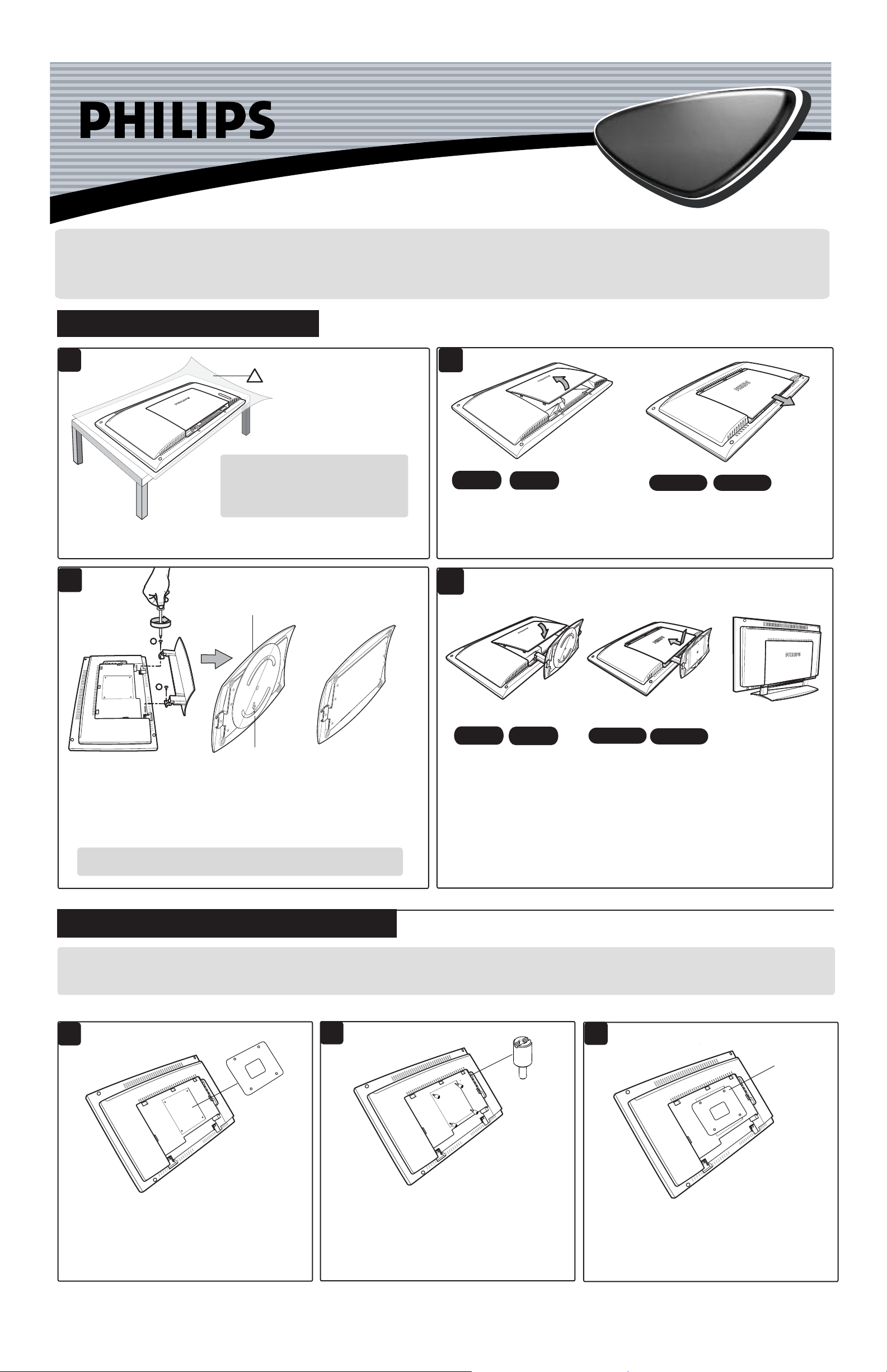
Ensure you have the following before
you assemble the stand :
– Two screws (supplied with set)
– One Screwdriver (not supplied)
Place the set facing down on a protective
sheet close to the edge of a flat surface.
23"/58cm
For the 20"/23" models, open back
plate cover by gently pulling upwards.
20"/51cm
17"/44cm
For the 15"/17" models, open back
plate cover by sliding the plate cover
downwards and then pull upwards.
15"/39cm
4
Bottom of swivel base
(20"/23" models only)
1
2
NOTE : No swivel
base for 15"/17" models
17"/44cm
For the 15"/17" models,
close back plate cover by
sliding plate upward.
15"/39cm
Align arrow
to the center
For swivelling of the stand to function properly, adjust the swivel base at
the back of the stand until arrow is aligned in the center. Align the stand
studs into the holes at the bottom of the set. Put in the screws (provided)
into the 2 holes and tightened with a screwdriver.
CAUTION : While putting in the screws, hold onto the stand.
23"/58cm
For the 20"/23"models,
close back plate cover
by gently pushing
downwards.
20"/51cm
INSTALLING LCD TV ON THE WALL
If you intend to install the LCD TV on the wall. ensure you have the following :
– Standard VESA 100 bracket for 15"/17"/20"/23" LCD TV (not supplied) and four spacers found in the accessory bag.
Do the following when installing the LCD TV on the wall :
1
Ñ
VESA
Bracket
does not
fit
2
Ñ
Spacer
x 4
3
Ñ
Check the stand arm
is rigid and properly
installed. Place the
set upright.
Tighten
VESA
bracket
to spacers
If your VESA bracket does not fit into the slot at
the rear of the LCD TV, proceed to make use of
the four spacers provided. Note : If VESA bracket
fits into the slot, you need not use the spacers.
Screw the four spacers to the holes at the rear of
the set. Ensure the spacers are properly tightened
(torque of 1.2N-m or 1 lbf-in).
3139 125 32112
Place the VESA bracket on the spacers and
tightened with the VESA bracket screws.
Page 2
LCD TV
LCD TV
Quick Use and Hookup Guide
C
ONTENTS
Presentation of the LCD Televison . . . . . . . . . . . 2
Remote Control Operation . . . . . . . . . . . . . . . . . 2
Hooking Up the Television
Remote Control Batteries . . . . . . . . . . . . . . . . . . . 3
Cable/Cable Box TV . . . . . . . . . . . . . . . . . . . . . . 3
Antenna TV . . . . . . . . . . . . . . . . . . . . . . . . . . . . . 3
AV1 Inputs . . . . . . . . . . . . . . . . . . . . . . . . . . . . . . 4
Component (CVI) Inputs. . . . . . . . . . . . . . . . . . . 4
HD (High Definition Inputs. . . . . . . . . . . . . . . . . 4
PC (Monotor) Inputs. . . . . . . . . . . . . . . . . . . . . . . 4
AV2 Inputs . . . . . . . . . . . . . . . . . . . . . . . . . . . . . . 4
Monitor Outputs . . . . . . . . . . . . . . . . . . . . . . . . . . 4
PRESENTATION OF THE LCD TELEVISION
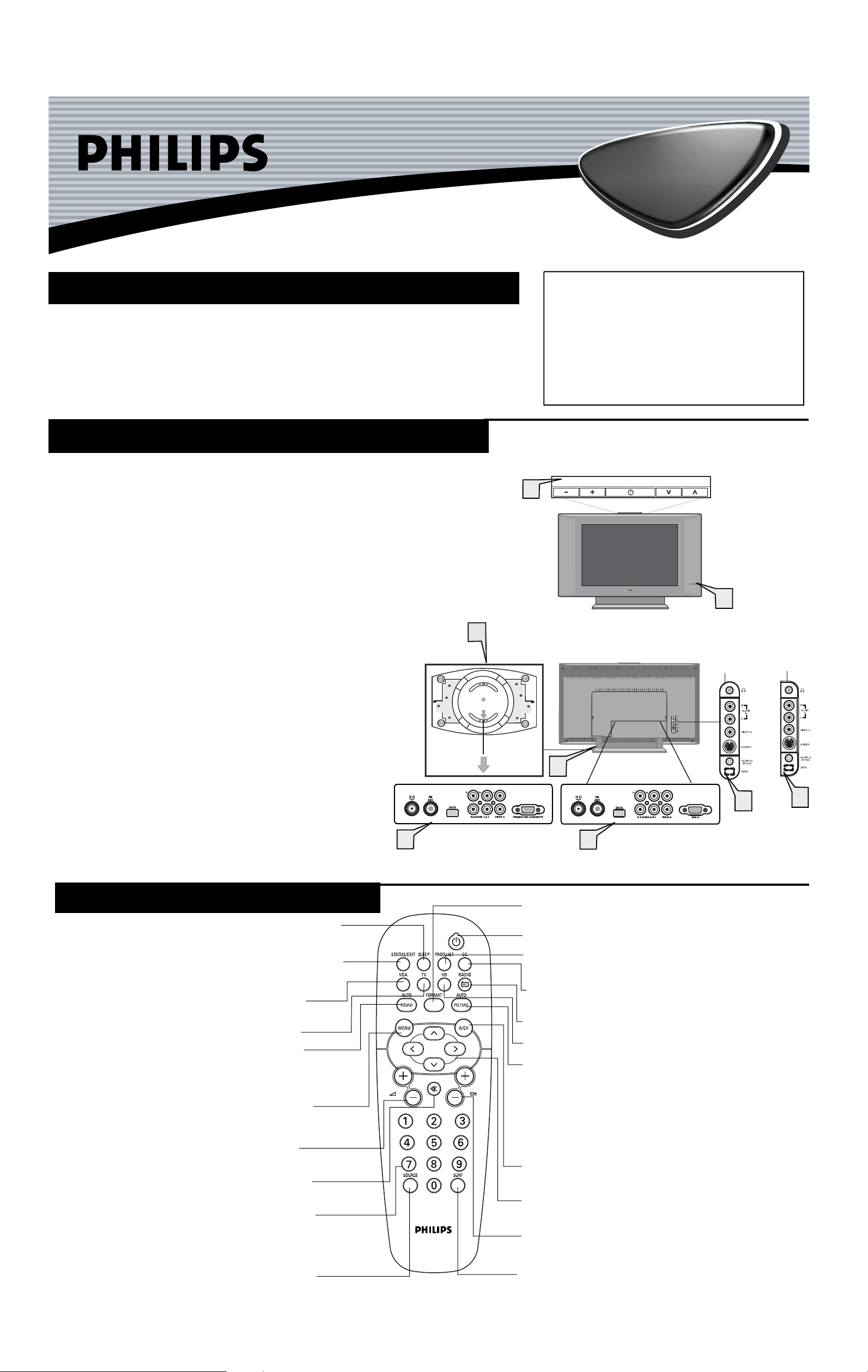
Television keys
1
• 2 : to switch the TV on or off.
• VOLUME + / – : to adjust sound level.
• PROGRAM + /– : to select programmes.
To access or close menus, press the VOLUME + / –
keys simultaneously. The PROGRAM + / – keys can
be used to select an adjustment and the VOLUME + / –
keys make that adjustment.
Adjustable stand
The stand has swivel and tilt functions. For swivelling function,
2
ensure the arrows at the bottom of the stand arm and the
swivel base are aligned in the center (see diagram on the right).
For tilting function, you can tilt the set backward or forward to
your preferred angle.
Note : The stand can be removed and the LCD TV can be
installed on the wall. This set has four mounting interfaces fulfilling
VESA specifications. Pull out the back plate cover to access the four
installing interfaces. Installation of the LCD TV on the wall should
be carried out by qualified servicemen.Improper or incorrect
installation may render the set unsafe.
LED light and infrared sensors
Aim remote control at infrared sensors to activate TV controls.
3
Bottom of
swivel base
2
IMPORTANT
NOTE: This owner's manual is used with several
different television models. Not all features (and
drawings) discussed in this manual will necessarily
match those found with your television set. This is
normal and does not require that you contact your
dealer or request service.
WARNING: TO PREVENT FIRE OR SHOCK
HAZARD DO NOT EXPOSE THIS UNIT TO
RAIN OR EXCESSIVE MOISTURE.
1
VOLUME
2
PROGRAM
3
17"/20"/23"
models only
15" model
only
4
Rear connectors
Located at the rear of the set.
Bottom connectors
Located at the bottom of the set.
5
REMOTE CONTROL OPERATION
Sleep Button - Press to set the TV to automatically turn itself
OFF at a given amount of time.
Status/Exit Button - Press to see the current channel number
on the TV screen. Also press to clear the TV menu after
control adjustments.
VGA Mode Button - Press to directly enter PC mode.
Appicable to 15"/17"/23" models only.
TV Mode Button - Press to directly enter TV mode.
Auto Sound Button - Press to select an AutoSound™
control. Choose from three factory-set controls (VOICE, MUSIC,
and THEATRE) and a PERSONAL to tailor the TV sound to
enhance the particular type of program you are watching.
Menu Button - Press for the onscreen menu to appear.
Pressing the menu button after menu selections are made
will exit the menu from the TV screen.
Volume (+) or (–) Buttons - Press to adjust the TV
sound level.
Mute Button - Press to turn the TV sound OFF . Press
again to return the sound to its previous level.
Number Buttons - Press the number buttons for direct
access to the TV channels. For a 2-digit channel, enter
the 2nd digit before the dash disappears. For a 3-digit
channel, enter the first digit followed the next 2 digits.
5
20" model only
4
15"/17"/23" models only
5
Format Button - Press to toggle the different screen format
options.
Power Button Program List - Press to display a list of channel numbers.
Each channel will appear as a selectable menu item.
CC Button - Press to select Closed Captioning options
within the menu.
FM Radio Mode Button - Press to directly enter Radio mode.
HD Mode Button - Press to directly enter HD mode.
Auto Picture Button - Press to select an AutoPicture™
control. Choose from four factory-set controls (MOVIES,
SPORTS, WEAK SIGNAL and MULTI MEDIA) and a
PERSONAL control that you set according to your own
preferences through the onscreen PICTURE menu. The four
factory-set controls will tailor the TV picture so as to enhance
the particular type of program you are watching, or to improve
the picture of a program that has a weak signal.
A/CH Button - Press to toggle between the currently viewed
channel and the previously viewed channel.
Cursor Buttons (Left, Right, Up, Down) - Press these buttons
to highlight, select, and adjust items on the TV's onscreen menu.
Channel (+) or (–) Buttons - Press to access the next or
previous channel.
Press to turn the TV ON and OFF.
4
Source Button -
A/V Input jack connections and the currently tuned
channel.
Press to toggle between the different
Surf Button - Press to select previously viewed channels.
You can place up to 10 channels in memory. Then by pressing
the SURF button you can quickly view the select channels.
2
Page 3
3
HOOKING UP THE TELEVISION
A
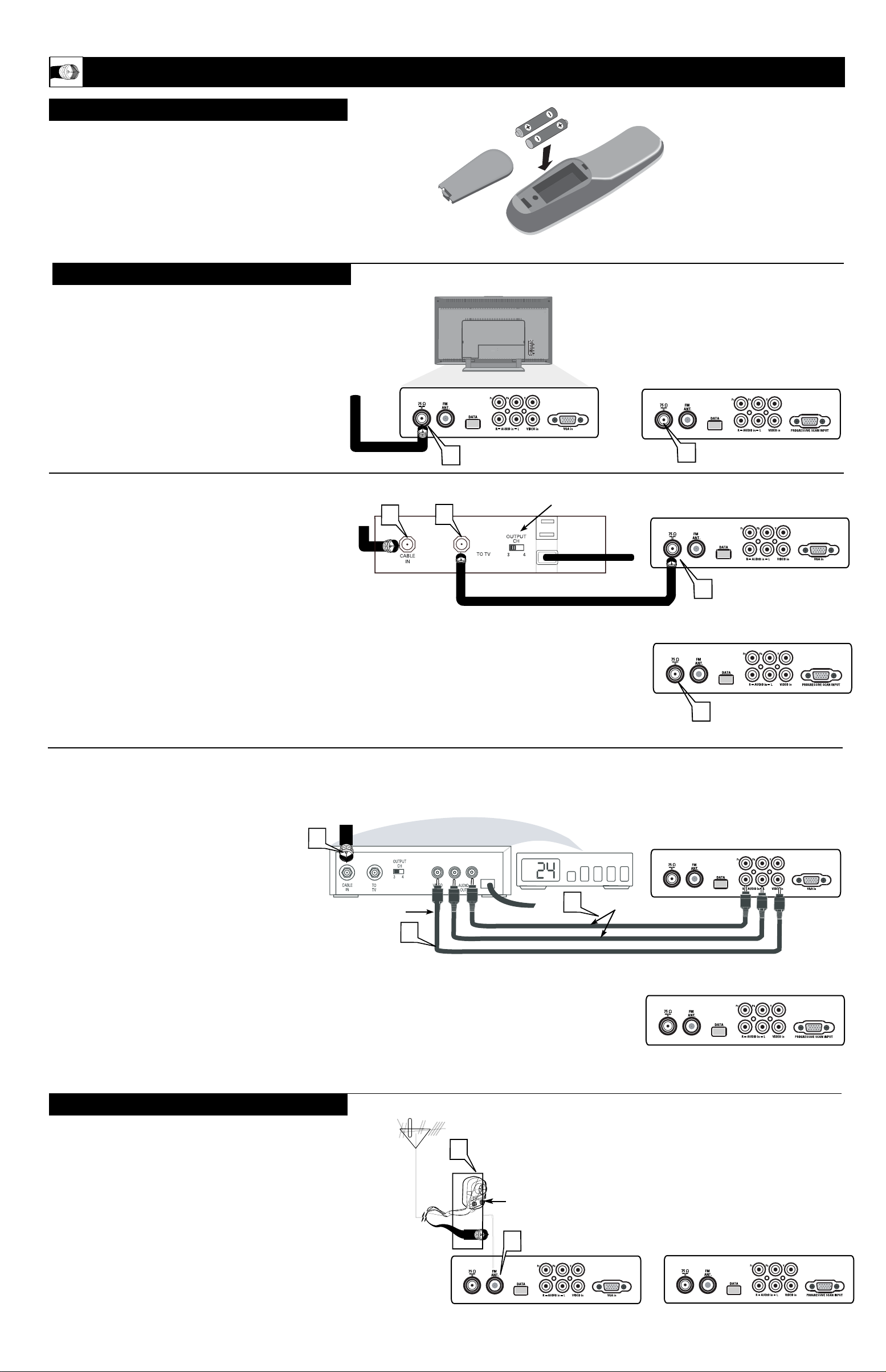
combination antenna receives normal broadcast channels (VHF 2–13 and UHF 14–69). Your connection is
easy because there is only one 75
Ω
(ohm) antenna plug on
the back of your TV, and that’s where the antenna goes.
1
If your antenna has a round cable (75 ohm) on the end,
then you're ready to connect it to the TV.
If your antenna has flat, twin-lead wire (300 ohm), you
first need to attach the antenna wires to the screws on a
300- to 75-ohm adapter.
2
Push the round end of the adapter (or antenna) onto the
75
Ω
(ohm) plug on the bottom of the TV. If the round end
of the antenna wire is threaded, screw it down finger tight.
ANTENNA TV, FM
Antenna Connection:
Outdoor or Indoor Antenna (Combination VHF/UHF)
The combination antenna receives normal broadcast
channels 2-13 (VHF) and 14-69 (UHF).
Y
our Cable TV input into your home may be a single
(75 ohm) cable or use a cable box decoder. In either
case the connection is very simple. Follow the steps
below to connect your cable signal to your new television.
Direct Cable Connections:
This connection will supply Stereo sound to the TV.
Connect the open end of the round Cable Company supplied cable to the 75
Ω
input on the bottom of the TV. Screw
it down finger tight.
Cable Box (w/RF In/Outputs):
This connection will NOT supply Stereo sound to the TV.
The sound from the cable box will be mono.
1
Connect the open end of the round Cable Company supplied cable to
the cable signal IN(put) plug on the back of
the Cable Box.
2
Using a separate round coaxial cable, connect one end to the
OUT(put) (TO TV) plug on the back of the Cable Box.
3
Connect the other end of the round coaxial cable to the
75Ω input on the bottom of the television. Screw it down finger tight.
NOTE: Be sure to set the OUTPUT CHANNEL SWITCH on the
back of the cable box to CH 3 or 4, then tune the cable box on the
TV to the corresponding channel. Once tuned, change channels at
the cable box, not the television.
Cable Box (w/Audio/Video Outputs):
This connection will supply Stereo sound to the TV.
1
Connect the open end of the round Cable
Company supplied cable to
the cable signal
IN(put) plug on the back of the Cable Box.
2
Using an RCA type Video Cable, connect one end
of thecable to the Video (yellow) (or ANT , your
cable box may belabeled differently) Out jack on
the cable box and the otherend to the Video end of
the composite adapter included with the TV..
3
Using an RCA type Audio Left and Right Cable,
connect oneend to the left and right Audio Out
L and R jacks (red and white) on the cable box.
Connect the other ends to the Audio end of the
composite adapter cable included with the TV.
Connect the adapter into the AV In jack on the
bottom of the TV.
NOTE: Use the Source button on the remote control to
tune to the AV1 channel for the cable box signal. Once
tuned, change channels at the cable box, not the television.
Pressing the Source button repeatedly will scroll all the
AV input channels, including the presently tuned channel.
CABLE/CABLE BOX TV
Direct Cable Connection
Cable Box with Audio/Video Outputs Connection:
Cable Signal IN
from the Cable Company
T
o load the supplied batteries into the remote:
1
Remove the battery compartment door on the back of the
remote.
Place the two batteries in the remote. Be sure the (+) and (–)
ends of the batteries line up correctly (the inside of the case is
marked).
Reattach the battery compartment door.
2
3
REMOTE CONTROL BATTERIES
1
Cable signal
coming from
Cable Company
(Round 75
coaxial cable)
Ω
Jack Panel at bottom of TV
1
Direct Cable Connection
1
2
15"/17"/23" models only
Output Channel Switch
Ω
Round 75
Coaxial Cable
Jack Panel at bottom of TV
1
Jack Panel at bottom of TV
20" model only
15"/17"/23" models only
3
Jack Panel at bottom of TV
1
Jack Panel at back of Cable Box with AV option
Video Cable
(Yellow)
3
Audio Cables L & R
(Red / Whiite)
2
20" model only
3
Jack Panel at bottom of TV
15"/17"/23"
models only
Jack Panel at bottom of TV
1
Twin
Lead
Wire
Round 75
Coaxial Cable
from Antenna
Ω
300 to 75-ohm
Adapter
2
Jack Panel at bottom of TV Jack Panel at bottom of TV
15"/17"/23" models only
20" model
only
20" model only
Page 4
HOOKING UP THE TELEVISION
4
I
1
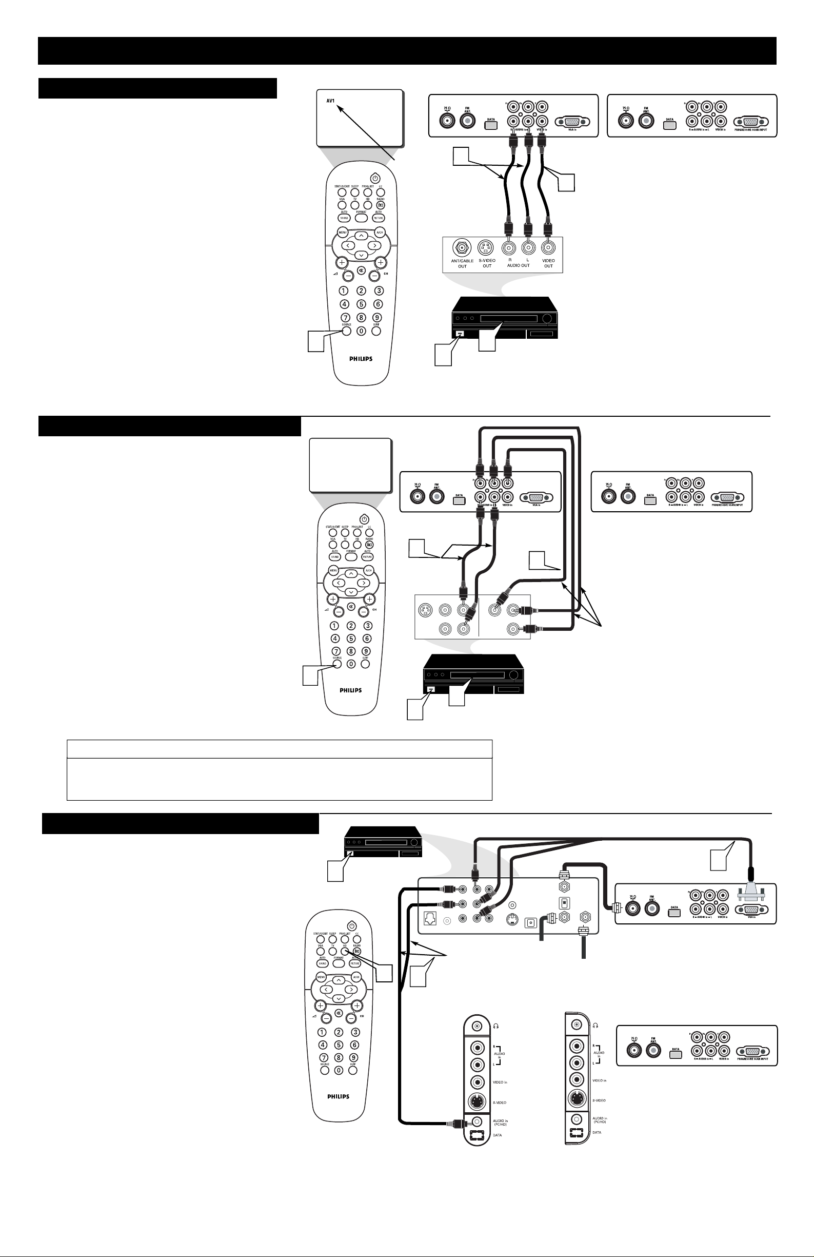
Connect the Component (Y, Pb Pr) Video
Out jacks from the HD Receiver (or similar
device) to the VGA In jack (15"/17"/23" models)
via the VGA cinch to cable ( not supplied with set)
or to the PROGRESSIVE SCAN INPUT
(20" model) jack on the bottom of the TV.
Connect the red and white AUDIO CABLES
to the Audio (left and right) output jacks on the
rear of the HD Receiver to the
AUDIO PC/HD
jack at the bottom of the TV.
Turn the TV and the HD Receiver ON.
Press the HD Mode button to set the TV into
the HD Mode and tune to the HD signal.
2
3
4
HD (HIGH DEFINITION) INPUTS
T
he audio/video input jacks on the bottom panel of
the TV are for direct picture and sound connections
between the TV and a VCR (or similar device) that has
audio/video output jacks.
1
Connect the VIDEO OUT (yellow) jack of the
VCR to the VIDEO IN jack on the bottom of the TV.
Connect the AUDIO OUT (left and right) jacks
of the VCR to the AUDIO IN (left and right) jacks
on the bottom of the TV.
Turn the VCR or accessory device and the TV ON.
Press the SOURCE button button on the remote
control to select AV1 channel for the accessory device.
AV1 will appear in the upper left corner on the TV
screen when tuned properly.
With the VCR (or accessory device) ON, press
the PLAY button of the VCR to view the tape
on the television.
2
3
4
AV1 INPUTS
VCR (or accessory device)
(EQUIPPED WITH VIDEO AND
AUDIO OUTPUT JACKS)
BACK OF VCR
(or Accessory device)
C
omponent Video inputs provide the highest possible color
and picture resolution in the playback of digital signal
soure material, such as with DVD players.
Connect the Component (Y, Pb, Pr) Video OUT
jacks from the DVD player (or similar device) to the
COMP(onent) VIDEO Input (Y green, Pb blue,
Pr red) jacks on the bottom of the TV. When using
the Component Video Inputs, it is best not to connect
a signal to the AV1 IN Video Jack. The CVI
connection will dominate over the AV1 in Video
Input jack.
Connect the red and white AUDIO CABLES to the
Audio (left and right) output jacks on the rear of the
accessory device to the AV1 in Input Jacks on the TV.
Turn the TV and the DVD (or digital accessory
device) ON.
Press the SOURCE button on the remote control to
select CVI channel for the accessory device. CVI will
appear in the upper left corner on the TV screen.
Insert a DVD disc into the DVD player and press
the PLAY É button on the DVD Player
C
OMPONENT
(CVI) I
NPUTS
The description for the component video connectors may differ depending on the DVD player or
accessory digital source equipment used (for example, Y, Pb, Pr; Y, B-Y, R-Y; Y, Cr, Cb). Refer
to your DVD or digital accessory owner's manual for definitions and connection details.
HELPFUL HINT
5
Note : The Audio/Video cables needed for this connection are
not supplied with your TV. Please contact your dealer or Philips
at 800-531-0039 for information about purchasing the needed cables.
4
Tune
To AV1
Channel
Jack Panel at bottom of TV
2
Audio Cables
(Red/White)
5
3
15"/17"/23"
models only
1
Video Cable
(Yellow)
Jack Panel at bottom of TV
20" model only
1
2
3
4
5
CVI
Jack Panel at
bottom of TV
15"/17"/23"
models only
Jack Panel at bottom of TV
20" model only
2
Audio Cables
(Red/White)
S-VIDEO
OUT
VIDEO
OUT
AUDIO
OUT
COMP VIDEO
R
Y
L
4
5
3
1
Pr
Pb
ACCESSORY DEVICE
(Equipped with Component
Video Outputs)
Component Video Cables
(Green/Blue/Red)
f your are using a High Definition receiver that can transmit
high definition programming, the TV can accept those signals
through the HD Inputs located on the bottom of the TV.
3
HD RECEIVER
(Equipped with
Component
Video Outputs)
4
Audio Cables
2
(Red/White)
AUDIO
L
R
RF
VIDEO
REMOTEPHONE JACK
AUDIO
Y
PB
PR
VIDEO
in 2
in 1
JACK PANEL
at REAR of TV
L
VCR
CONTROL
DIGITAL
AUDIO OUT
S-VIDEO
Coaxial Cable Lead-in
from Cable Outlet,
or VHF/UHF Antenna
OUT TO TV
CH 3
CH 4
IN FROM ANT SATELLITE IN
Coaxial Cable Lead-in
from Satellite Dish Antenna
JACK PANEL
at REAR of TV
VGA to Cinch cable
Jack Panel at
bottom of TV
Jack Panel at bottom of TV
20" model only
1
15"/17"/23"
models only
Rear of HD Receiver (Illustration is for reference
Note :
only.Your HD Receiver's jack panel may look and be
labelled differently.)
this connection are not supplied with your TV. Please
contact your dealer or Philips at 800-531-0039 for
information about purchasing the needed cables.
The Audio/Video cables needed for
17"/20"/23"
models only
15" model
only
Page 5
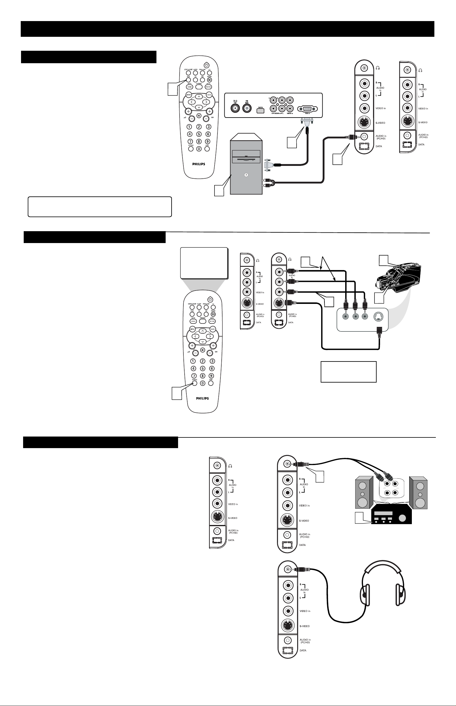
HOOKING UP THE TELEVISION
PC (MONITOR) INPUTS
his TV can be used as a PC Monitor. Your computer
T
will have to be equipped with a VGA type video output
and VGA cable.
Appicable to 15"/17"/23" models only.
20" model is for 480p Progressive Scan DVD
playback.
Connect one end of the VGA video cable to the
Monitor (video) output on the computer to the PC
1
Input (VGA) jack on the bottom of the TV.
Connect the AUDIO PC/HD cable of the TV to
the Audio output on the PC.
2
Turn the TV and the Computer ON.
3
Press the VGA Mode button to set the TV into the
VGA Mode and tune to the computer's signal.
4
Note : For the display resolutions available to your
TV, refer to the Operating Instruction Manual
Please contact your dealer or Philips at 800-531-0039 for
information about purchasing the needed cables.
4
3
JACK PANEL
at REAR of TV
PC
15"/17"/23"
models only
1
VGA
Cable
Audio
Cable
2
JACK PANEL
at REAR of TV
17"/20"/23"
models only
JACK PANEL
at REAR of TV
15" model
only
AV2 (SIDE) INPUTS
uch like the AV1 jacks, the AV2 jacks allow for
extra accessory device connections for items such
M
as cameras or gaming stations. The AV2 Input Jacks are
located on the rear of the TV.
Connect the VIDEO OUT (yellow) jack of the
Accessory device to the VIDEO IN jack on the
1
bottom of the TV. If your accesory device is
equipped with a S-VIDEO jack, do not connect
to the VIDEO jack. Connect to the S-VIDEO
jack instead.
Connect the AUDIO OUT (left and right) jacks
of the Accessory device to the AUDIO IN (left
2
and right) jacks on the bottom of the TV.
Turn the Accessory Device and the TV ON.
3
Press the SOURCE button button on the remote
control to select AV2 channel for the accessory
4
device. AV2 will appear in the upper left corner
on the TV screen when tuned properly.
With the Accessory Device ON, press the PLAY
button to activate the playback on the television.
5
4
AV2
JACK PANEL
at REAR of TV
15" model
only
JACK PANEL
at REAR of TV
17"/20"/23"
models only
AUDIO CABLES
2
VIDEO CABLE
OR
1
RIGHT LEFT
ACCESSORY DEVICE
JACK PANEL
S-VIDEO CABLE
AN S-VIDEO CABLE CAN
BE USED IN PLACE OFTHE
YELLOW VIDEO CABLE IF
DESIRED.
VIDEOAUDIO
ACCESSORY DEVICE
(Camcorder, Camera,
etc..)
3
5
S-VIDEO
MONITOR OUTPUTS
he Audio headphone jack can be used to connect an
T
external audio system for better audio sound or to
a headphone in any of the available modes.
If connected to an audio system or a headphone, there will
be no sound from the TV speakers. The sound will come
fom the audio system of the headphone.
Connect Headphone jack located on the right rear of
the TV to the R and L audio input jacks on your sound
1
system or to your headphone set.
Turn the TV and Audio system/Headphone ON.
The TV sound can be heard through the Audio
2
system/Headphone.
15" model
only
JACK PANEL
at REAR of TV
17"/20"/23"
models only
JACK PANEL
at REAR of TV
1
Headphone Cable
Audio System Connection:
AUDIO CABLES
(Red & White)
R
L
T
U
P
IN
V
/T
X
U
A
T
U
P
IN
O
N
O
H
P
2
AUDIO SYSTEM
with AUDIO INPUTS
HEADPHONE
Headphone Connection:
5
 Loading...