

PHILIPS 201P1074 User Manual

Philips 201P Electronic User's Manual
file:///G|/manual/english/201P/index.htm [10/16/1999 6:36:02 AM]

Safety and Troubleshooting Information
Safety Precautions and Maintenance • Troubleshooting • Regulatory Information • Other
Related Information
Safety precautions and maintenance
WARNING: Use of controls, adjustments, or procedures other than those
specified in this documentation may result in exposure to shock, electrical
hazards, and/or mechanical hazards.
Read and follow these instructions when connecting and using your computer monitor:
Disconnect the monitor from the power supply if the monitor is not to be used for an extended period
of time.
●
Do not attempt to remove the back cover, as you will be exposed to a shock hazard. The back cover
should only be removed by qualified service personnel.
●
Do not place objects on top of the monitor cabinet, objects could fall into vents or cover them and
prevent proper cooling of the monitor's electronic devices.
●
To avoid the risk of shock or permanent damage to the set, do not expose the monitor to rain or
excessive moisture.
●
Do not use alcohol or ammonia-based liquid to clean the monitor. If necessary, clean with a slightly
damp cloth. Disconnect the monitor from the power supply before cleaning.
●
Consult a service technician if the monitor does not operate normally when operating instructions of this
manual are followed.
RETURN TO TOP OF THE PAGE
Safety & Troubleshooting
file:///G|/manual/english/201P/safety/safety.htm [10/16/1999 6:36:08 AM]

About This Electronic User's Manual
About This Guide • Other Documents You May Need • Notational Descriptions
About This Guide
This electronic user's guide is intended for anyone who uses the Philips 201P Color Monitor. It describes the
monitor's features, setup, operation and all other information, which is the same exact information described
in our printed version.
The sections are as follows:
Safety and Troubleshooting Information provides tips and solutions for common problems, and other
related information you may need.
●
About This Electronic User's Manual gives overview of what information are included as well as
notation icon descriptions and other documentation you can refer to.
●
Product Information gives an overview of the monitor's features and as well as the technical
specifications for this monitor.
●
Installing Your Monitor describes the initial setup process and gives an overview of how to use the
monitor.
●
On Screen Display provides information on adjusting the settings on your monitor.●
Customer Care and Warranty is a list of worldwide Philips consumer information centers along with
the help desk phone numbers and information on the applicable warranty of your product..
●
Glossary provides more information for technical terms.●
Download Option allows you to consumer keep a copy of the entire manual in your hard drive.●
RETURN TO TOP OF THE PAGE
Other Documents You May Need
In addition to this Electronic User's Guide, you may need to refer to the following documentation:
Philips Color Monitor Quick Start Guide which summarizes the steps for setting up the monitor. This is
included with this product.
●
RETURN TO TOP OF THE PAGE
Notational Descriptions
The following subsections describe notational conventions used in this document.
About This Electronic User's Manual
file:///G|/manual/english/201P/about/about.htm (1 of 2) [10/16/1999 6:36:09 AM]
Notes, Cautions, and Warnings
Throughout this guide, blocks of text may be accompanied by an icon and printed in bold type or in italic type.
These blocks are notes, cautions, and warnings, and they are used as follows:
NOTE: This icon indicates important information and tips that help you make better
use of your computer system.
CAUTION: This icon indicates information that tells you how to avoid either potential
damage to hardware or loss of data.
WARNING: This icon indicates the potential for bodily harm and tells you how to
avoid the problem.
SMART HELP: This icon indicates helpful information when adjusting the On Screen
Display of your monitor.
Some warnings may appear in alternate formats and may be unaccompanied by an icon. In such cases, the
specific presentation of the warning is mandated by regulatory authority.
RETURN TO TOP OF THE PAGE
©1999 Koninklijke Philips Electronics N.V.
All rights reserved. Reproduction, copying, usage, modifying, hiring, renting, public performance, transmission and/or broadcasting in whole or in
part is prohibited without written consent of Philips Electronics N.V.
About This Electronic User's Manual
file:///G|/manual/english/201P/about/about.htm (2 of 2) [10/16/1999 6:36:09 AM]

Product Information
Product Features • Technical Specifications • Automatic Power Saving • Physical
Specification • Pin Assignment • Product Views
Product Features
201P10:
21-inch (20.0" VIS) Real Flat color monitor featuring ICE technology for excellent front of screen
performance for use with MACs, PCs or Workstations
●
Autoscan covers horizontal frequencies up to 121 kHz offering a maximum resolution of 2048 x 1536
with flicker free display of 1600 x 1200 at up to 97 Hz
●
Flat aperture grille CRT with high-resolution 0.25 mm stripe pitch.●
Auto Calibrate extends the useful life of the monitor by automatically adjusting color and luminance to
original values.
●
Large screen display in a small footprint: World's shortest 21-inch Flat monitor with maximum depth
of only 466 mm/18.3"
●
Outstanding ease of use thanks to CustoMax® monitor control software via USB●
TCO99, E2000, NUTEK, EPA, FCC, CE and ISO9241 certified●
RETURN TO TOP OF THE PAGE
Technical Specifications*
CRT
• Size and deflection
21 inch / 51 cm ; 90° deflection angle
• Dot pitch / Grille pitch 0.25 mm
• Horizontal pitch
• Tube type
Aperture grille, flat, high contrast, anti-glare, anti-static, anti
reflection, light transmission 41%
• Phosphor P22
• Recommended display area 15.4" x 11.6" / 392 x 294 mm
• Maximum display area 16.0" x 12.0" / 406 x 305 mm
SCANNING
• Horizontal scanning 30 - 121 KHz
• Vertical scanning 50 - 160 KHz
VIDEO
201P Product Information
file:///G|/manual/english/201P/product/product.htm (1 of 4) [10/16/1999 6:36:09 AM]
• Video dot rate 320 MHz
• Input impedance
- Video 75 ohm
- Sync 2.2 kOhm
• Input signal levels 0.7 Vpp
• Sync input signal
Separate sync
Composite sync
• Sync polarities Positive and negative
WHITE COLOR TEMPERATURE
Chromaticity CIE coordinates:
• at 9300 K degrees x = 0.283 / y = 0.297
• at 6500 K degrees x = 0.313 / y = 0.329
• at 5500 K degrees x = 0.332 / y = 0.347
* These information are subject to change without notice.
RETURN TO TOP OF THE PAGE
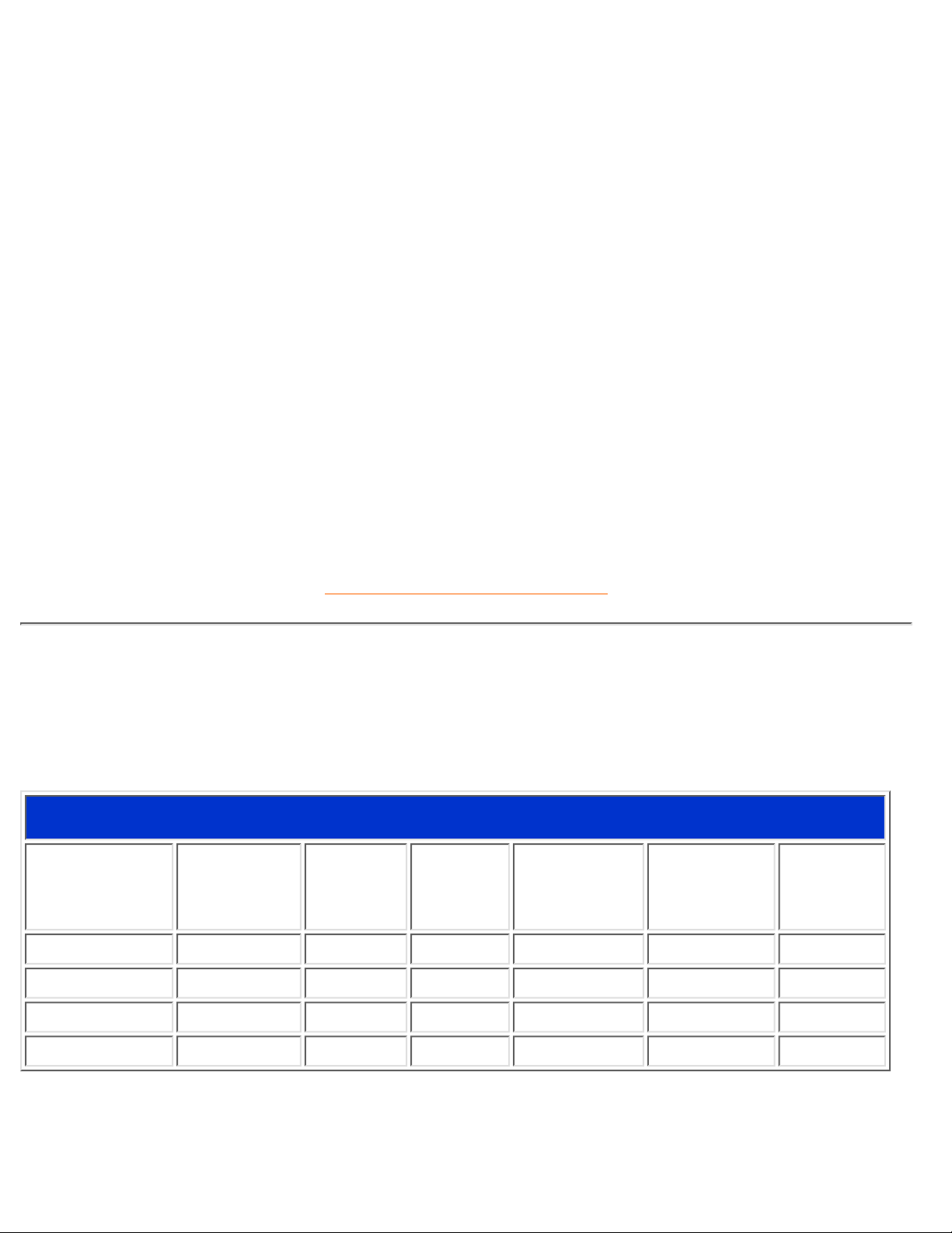
Automatic Power Saving
If you have VESA's DPMS compliance display card or software installed in your PC, the monitor can
automatically reduce its power consumption when not in use. And if an input from a keyboard, mouse or
other input device is detected, the monitor will automatically "wake up". The following table shows the power
consumption and signaling of this automatic power saving features:
Power Management Definition
VESA's Mode Video H-sync V-sync Power Used
Power
Saving (%)
LED color
ON Active Yes Yes Typical 124 W 0 % Green
Stand-by Blanked No Yes < 7 W 94 % Yellow
Suspend Blanked Yes No < 7 W 94 % Yellow
OFF Blanked No No < 2.8 W 98 % Amber
This monitor is ENERGY STAR® compliant. As an ENERGY STAR® Partner, PHILIPS has
determined that this product meets the
ENERGY STAR
®
guidelines for energy efficiency.
201P Product Information
file:///G|/manual/english/201P/product/product.htm (2 of 4) [10/16/1999 6:36:09 AM]

RETURN TO TOP OF THE PAGE
Physical Specifications
• Dimensions
19.7" x 19.7" x 18.3" / 501 x 501 x 466 mm (including base)
19.7" x 18.1" x 18.3" / 501 x 461 x 466 mm (excluding base)
• Weight 28.5 kg
• Power supply 90 - 264 VAC, 50/60Hz
• Temperature (operating) 0° to 35°C / 32° to 95°F
• Temperature (storage) -25° to +65°C / -13° to -149°F
• Relative humidity 5% to 95%
* Resolution 1280 x 1024, standard size, contrast max., brightness 50%, 9300°, full white pattern.
* These information are subject to change without notice.
RETURN TO TOP OF THE PAGE
Pin Assignment
The 15-pin D-sub connector (male) of the signal cable (IBM systems):
Pin
No.
Assignment
Pin
No.
Assignment
1 Red video input 9 No pin
2 Green video input 10 Logic ground
3 Blue video input 11
Identical output - connected
to pin 10
201P Product Information
file:///G|/manual/english/201P/product/product.htm (3 of 4) [10/16/1999 6:36:09 AM]
4
Identical output - connected
to pin 10
12 Serial data line (SDA)
5 Ground 13 H. Sync / H+V
6 Red video ground 14 V. Sync (VCLK for DDC)
7 Green video ground 15 Data clock line (SCL)
8 Blue video ground
RETURN TO TOP OF THE PAGE
Views
Follow the links to see various views of the monitor and its components.
Front View
Rear View
RETURN TO TOP OF THE PAGE
201P Product Information
file:///G|/manual/english/201P/product/product.htm (4 of 4) [10/16/1999 6:36:09 AM]

Installing your Monitor
Front View • Rear View • PCUH411 USB Hub (option)
Front View
Power button switches your monitor on.
OK button which when pressed will take you to the OSD controls
Contrast hotkey. When the UP arrow is pressed, the adjustment controls
for the CONTRAST will show up.
UP and DOWN buttons are used when adjusting the OSD of your monitor
Installing your Monitor
file:///G|/manual/english/201P/install/install.htm (1 of 3) [10/16/1999 6:36:10 AM]

Brightness hotkey. When both the LEFT and RIGHT arrows are pressed
at the same time, then the adjustment controls for BRIGHTNESS will
show up.
LEFT and RIGHT buttons, like the UP and DOWN buttons, are also used
in adjusting the OSD of your monitor.
By pressing both the UP and OK buttons, you can easily access the Input
Signals A and/or B.
RETURN TO TOP OF THE PAGE
Rear View
Installing your Monitor
file:///G|/manual/english/201P/install/install.htm (2 of 3) [10/16/1999 6:36:10 AM]

1. D-Sub Port - Attach the D-Sub connector that comes with your monitor here.
Other end connects to your PC.
2. Power in - Attach power cable here.
3. USB Port - Attach your USB Upstream cable here. Connect the other end to
your USB hub or your PC's USB connector. (Not available on all models.)
4. BNC Connectors - Attach the connectors here to get the best video
performance from your monitor.
RETURN TO TOP OF THE PAGE
Installing your Monitor
file:///G|/manual/english/201P/install/install.htm (3 of 3) [10/16/1999 6:36:10 AM]

On-Screen Display
Description of the On-Screen Display • The OSD Tree • The OSD Controls
Description of the On Screen Display
What is the On-Screen Display?
This is a feature in all Philips monitors which allows an end-user to adjust screen performance of monitors
directly though an on-screen instruction window. The user interface provides user-friendliness and
ease-of-use when operating the monitor.
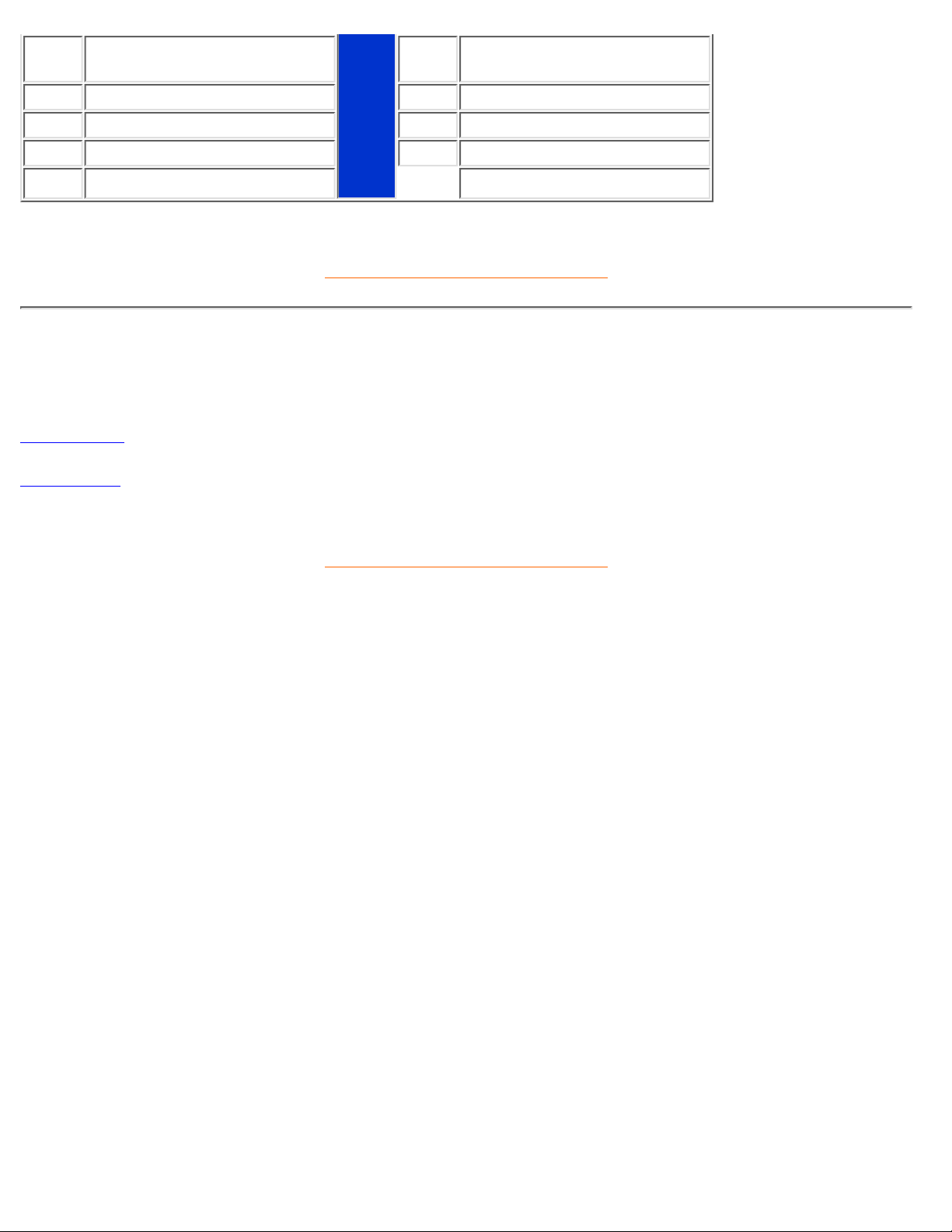
Basic and simple instruction on the control keys.
On the front controls of your monitor, once you press the
button, the On Screen Display (OSD) Main
Controls window will pop up and you can now start making adjustments to your monitor's various features.
Use the
or the keys to make your adjustments within.
On-Screen Display
file:///G|/manual/english/201P/osd/osddesc.htm (1 of 4) [10/16/1999 6:36:11 AM]
RETURN TO TOP OF THE PAGE
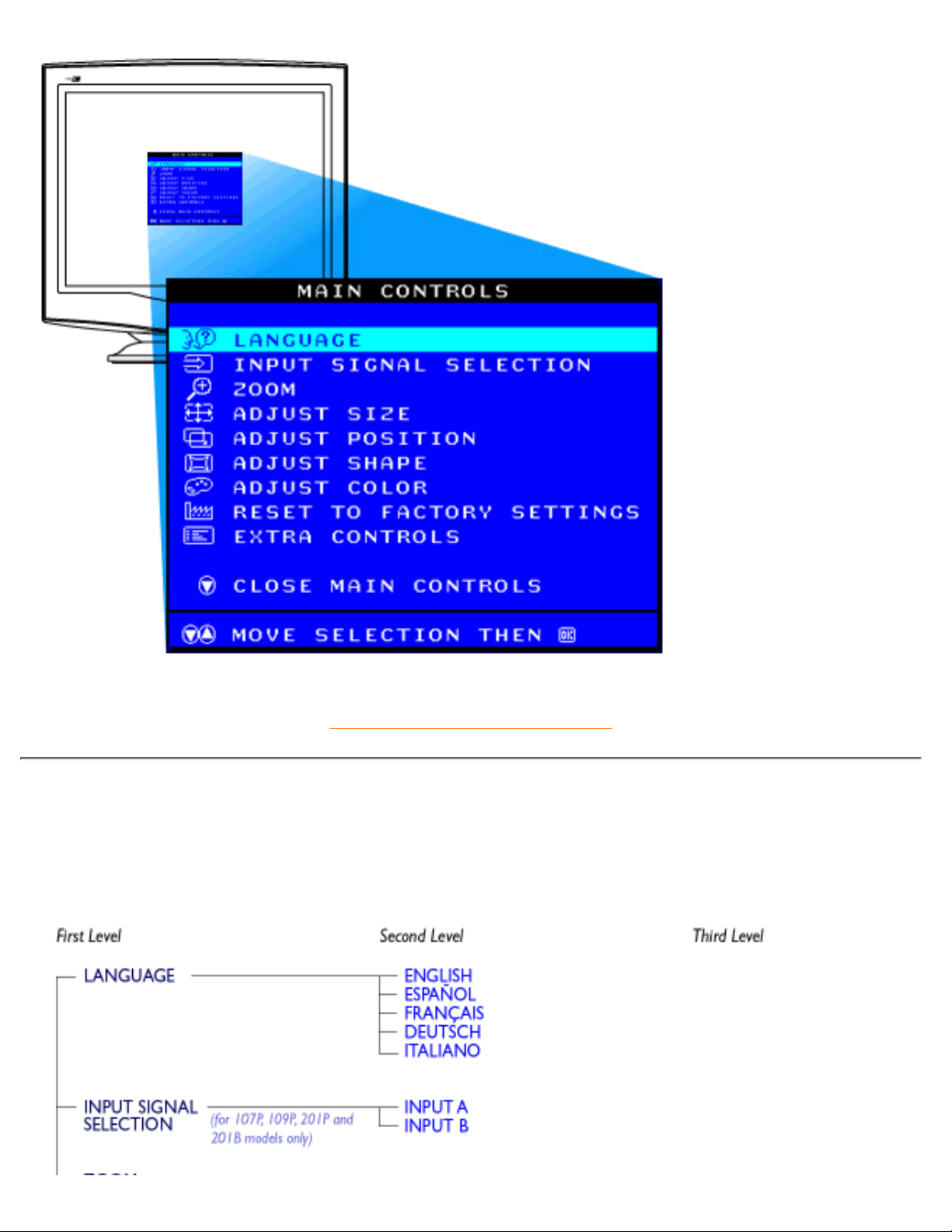
The OSD Tree
Below is an overall view of the structure of the On-Screen Display. You can use this as reference when you
want to later on work your way around the different adjustments.
On-Screen Display
file:///G|/manual/english/201P/osd/osddesc.htm (2 of 4) [10/16/1999 6:36:11 AM]

On-Screen Display
file:///G|/manual/english/201P/osd/osddesc.htm (3 of 4) [10/16/1999 6:36:11 AM]

RETURN TO TOP OF THE PAGE
On-Screen Display
file:///G|/manual/english/201P/osd/osddesc.htm (4 of 4) [10/16/1999 6:36:11 AM]

Customer Care & Warranty
PLEASE SELECT YOUR COUNTRY TO READ THE WARRANTY COVERED:
WESTERN EUROPE: Austria • Belgium • Cyprus • Denmark • France • Germany • Greece •
Finland • Ireland • Italy • Luxembourg • the Netherlands • Norway • Portugal • Sweden •
Switzerland • Spain • United Kingdom
EASTERN EUROPE: Czech Republic • Hungary • Poland • Russia • Turkey
LATIN AMERICA: Antilles • Argentina • Brasil • Chile • Colombia • Mexico • Paraguay • Peru
• Uruguay • Venezuela
NORTH AMERICA: Canada • USA
PACIFIC: Australia • New Zealand
ASIA: Bangladesh • China • Hong Kong • India • Indonesia • Japan • Korea • Malaysia •
Pakistan • Philippines • Singapore • Taiwan • Thailand
AFRICA: Morocco • South Africa
MIDDLE EAST: Dubai • Egypt
Customer Care and Warranty
file:///G|/manual/english/warranty/warranty.htm [10/16/1999 6:36:11 AM]
Glossary
A B C D E F G H I J K L M N O P Q R S T U V W X Y Z
A
Autoscan
A microprocessor-based feature of Philips Brilliance monitors is able to detect automatically horizontal and
vertical frequencies of input signals with those of the installed video card. An autoscan monitor can thus
operate with a wide range of video cards. MultiSync, a registered trademark of NEC, provides a similar
function.
RETURN TO TOP OF THE PAGE
B
Balanced pincushion
See Geometric distortion
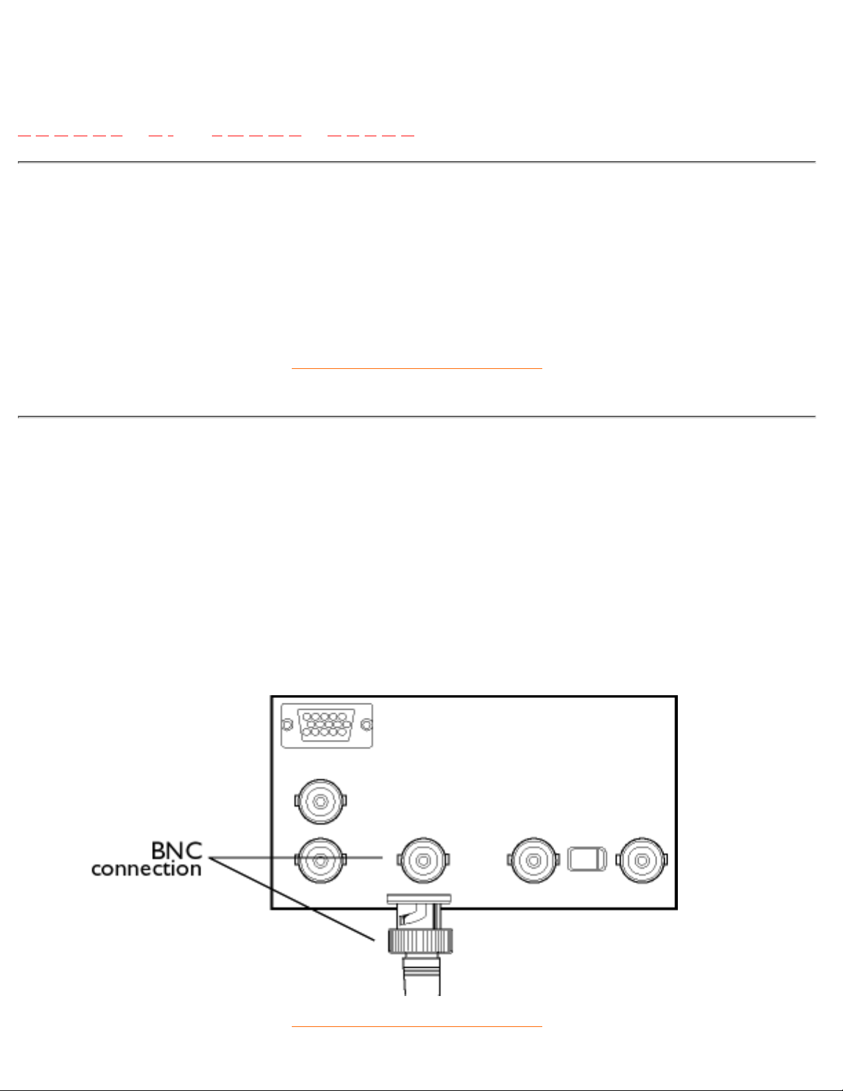
BNC connection
A special construction of connector used in some monitors with higher horizontal scanning frequency. The
BNC connection can provide the optimum shielding and matching characteristic impedance of video signal
path to ensure the best video performance.
RETURN TO TOP OF THE PAGE
Glossary
file:///G|/manual/english/201P/glossary/glossary.htm (1 of 18) [10/16/1999 6:36:13 AM]

C
CE Mark
CE mark is displayed on products per EMC and LV ( low Voltage Device ) directives in compliance with
European Community safety, EMI and EMS requirements and is compulsory on products for sale in the
European Community.
Color temperature
A way of describing the color of a radiating source in terms of the temperature (in degrees Kelvin) of a black
body radiating with the same dominant frequency as the source.
Most Philips monitors offer the possibility of setting the color temperature to any desired value.
Contrast
The ratio between the brightness of the brightest and darkest parts of a picture. The darkest part of a picture
is set by the brightness of the unexcited phosphor, which is governed by the degree with which ambient light
is reflected. Contrast is therefore reduced in conditions of high ambient light levels. Black Matrix tubes reflect
less ambient light so exhibit higher contrast than other tubes.
Convergence error
Bean misalignment causing one or more of the three beams passing through the wrong aperture in the
shadow mask and striking a phosphor dot in the wrong triad.
Convergence error is expressed in mm often at three well-defined points on the screen, designated A, B and
C (see figure ). Also known as misconvergence.
Glossary
file:///G|/manual/english/201P/glossary/glossary.htm (2 of 18) [10/16/1999 6:36:13 AM]
Points where convergence error is specified.
Convergence-error correction
A method of correcting for convergence error to insure that all three beams land simultaneously in the same
triad. This is usually accomplished by means of special convergence-error correction coils in the deflection
yoke.
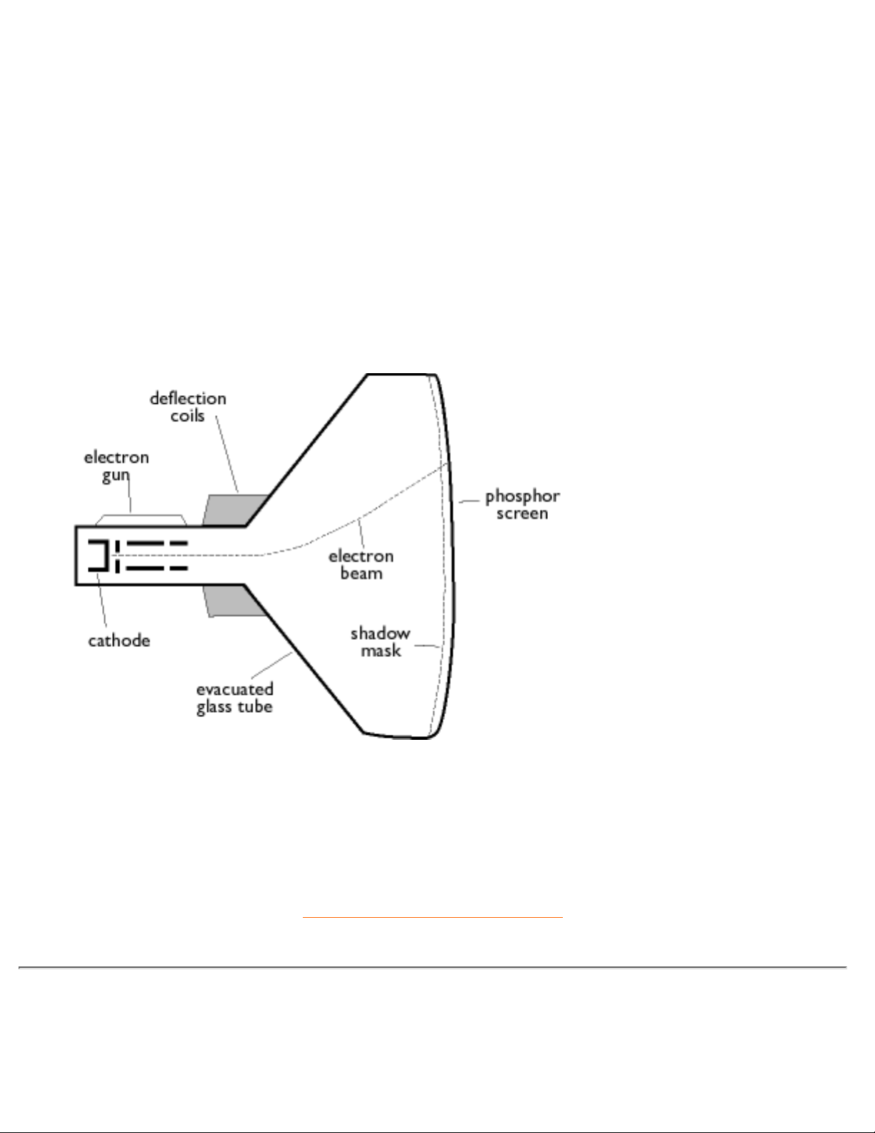
CRT
Cathode-ray tube - the general term for all tubes in which one or more electron beams emitted by a cathode
are periodically scanned across a phosphor screen by means of deflection circuitry. A special form of the
cathode-ray tube is the TV and monitor picture tube.
CustoMax
Philips proprietary monitor control software that allows users to control parameters (e.g., Size, Color,
Geometry) using software running in Windows. CustoMax is compatible with existing VGA cards. See
CrystalClear FAQ and USB Bay FAQ.
RETURN TO TOP OF THE PAGE
D
DDC (Display Data Channel)
Glossary
file:///G|/manual/english/201P/glossary/glossary.htm (3 of 18) [10/16/1999 6:36:13 AM]

DDC is a communication channel for displays and computers. The DDC feature allows the monitor controller
to be automatically configured to make optimal use of the display without manual user interaction. DDC is
implemented as part of the new Plug & Play approach introduced into the PC market to increase user
friendliness.
The three levels developed for Plug & play are: (1) DDC1, monitor send data to the PC; (2) DDC2B, PC can
request information from monitor; and (3) DDC2Bi which is a two-way communication - monitor can be
addressed and PC or graphics board can give commands to monitor.
DDC 1/2B
See DDC.
DDC 2Bi
See DDC.
Degaussing
The procedure of demagnetizing the shadow mask and associated metal parts of a picture tube at switch-on
to minimize picture distortion. This is usually accomplished by means of a special degaussing coil through
which a decaying alternating current is passed to generate an alternating magnetic field that gradually
decays to demagnetize the tube. Some monitors offer a manual degaussing facility that can be activated at
any time.
Digital control
Microprocessor-based digital control of picture parameters and video modes for complete control of picture
settings and modes and instant recall of all settings at the push of a button. This is a very advanced feature
that allows the user to switch to any required mode at any instant without having to spend time readjusting
the picture. It is currently available in most Philips monitors.
Dot pitch
The shortest distance between two phosphor dots of the same color on the screen. The smaller the dot pitch,
the better the resolution of the monitor.
Glossary
file:///G|/manual/english/201P/glossary/glossary.htm (4 of 18) [10/16/1999 6:36:13 AM]

Dot rate
Frequency in MHz of the dot clock. It is a measure of the speed with which data is transferred between the
video card and subsequent processing circuitry.
Also known as video dot rate.
RETURN TO TOP OF THE PAGE
E
Electromagnetic radiation standards
International standards set to limit electromagnetic emissions from monitors. There are currently two
important standards both derived from regulations originally laid down by Swedish authorities.
MPR-II
The standard originally proposed by the Swedish National Board of Measurement and Testing. It set
maximum levels of electromagnetic radiation emitted by monitors, and has now been adopted as a world
standard. MPR-II defines maximum permitted electrostatic, magnetic and electric field levels measured at a
distance of 50 cm from the center of the monitor (see table).
TCO
Glossary
file:///G|/manual/english/201P/glossary/glossary.htm (5 of 18) [10/16/1999 6:36:13 AM]

In 1991, the Swedish Tjänstemannens Central Organization (TCO, Swedish confederation of Professional
Employees ) set a standard even more severe than MPR-II, especially for alternating electric fields (AEF).
The TCO standard is more severe since not only are the permitted field levels reduced compared with
MPR-II, but the measuring distance is also reduced (see table).
Electromagnetic radiation standards
EMI (Electrical Magnetic Interference)
The electrical and/or magnetic radiation coming from the working electrical or electronic equipment.
EMS (Electrical Magnetic Sustainment)
The ability of electrical or electronic equipment to function properly in the environment with electrical and/or
magnetic interference.
RETURN TO TOP OF THE PAGE
F
Flicker
Very rapid variations in picture intensity caused by the finite time required for the electron beam to scan a
picture onto the screen. Two kinds of flicker occur: line flicker caused by the electron beam scanning-in each
line of the picture; and frame flicker (or field flicker if the picture is interlaced) caused by the frame repetition
rate of 50 frames/second. Frame flicker is noticeable with GUI and DTP software (which have a light
background), and can be very disturbing, especially for those who work regularly with displays - contributing
to eye strain, headaches, visual blurring, stress, etc. The problem can, however, be eliminated by increasing
the refresh rate (number of frames/second) of the monitor to a value above around 70 Hz. Sensitivity to
flicker appears to diminish with increasing age.
RETURN TO TOP OF THE PAGE
H
Hertz
The unit of frequency named after the physicist Heinrich Hertz (1857-1894). 1 hertz (Hz) is equal to 1
cycle/second.
Horizontal dot pitch
See Dot pitch.
Horizontal scanning frequency
Glossary
file:///G|/manual/english/201P/glossary/glossary.htm (6 of 18) [10/16/1999 6:36:13 AM]

Also called line frequency and expressed in kHz, it is the number of video lines written on the screen every
second (from left to right). The higher the horizontal scanning frequency, the better the resolution (i.e., the
higher the resolution and/or the higher the refresh rate).
RETURN TO TOP OF THE PAGE
I
INF File
INF file (Information File)
Information (INF) files store information in a specific format. The set-up functions retrieve information from
the INF file to use when performing installation operations. Examples of the type of information stored in an
INF file include INI and registry changes, file names, and locations of the source files on source media.
Interlaced/non-interlaced
Interlaced.
The method of writing a picture on the screen by initially writing all even lines and subsequently writing all
odd lines of the picture. Result: The complete picture is composed of two interlaced half pictures (or fields).
With interlacing, a vertical (or field) frequency of 50 Hz means a picture (or frame) frequency of 25 Hz.
Non-interlaced.
The method of writing a picture on the screen by successive video lines of the picture so that a full frame is
written onto the screen in one vertical sweep of the beams. With a non-interlaced display, a vertical
frequency of 50 Hz means a picture (or frame) frequency of 50 Hz. At any given resolution, non-interlaced
modes are preferable to interlaced modes; however, generation of non-interlaced modes is more expensive.
RETURN TO TOP OF THE PAGE
Glossary
file:///G|/manual/english/201P/glossary/glossary.htm (7 of 18) [10/16/1999 6:36:13 AM]
L
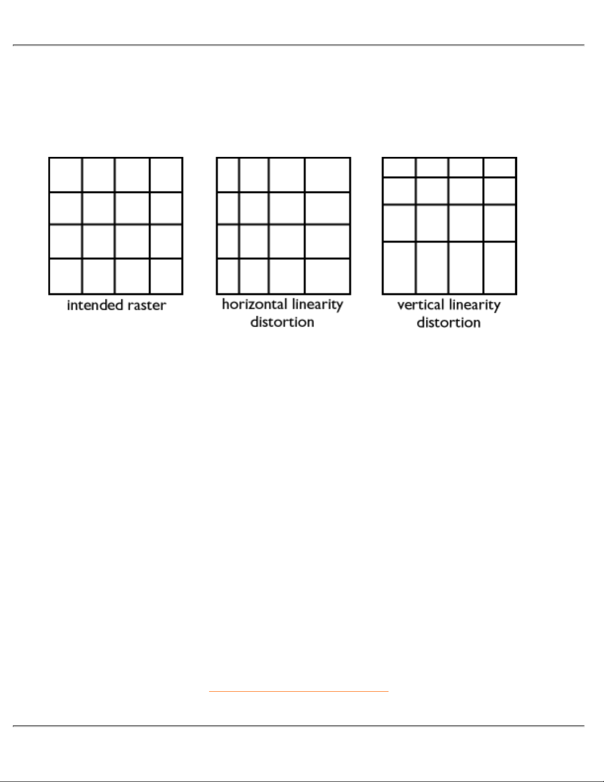
Linearity
The degree to measure the actual location of a pixel on the screen corresponds with its intended location. (
see figure )
Line frequency
See Horizontal scanning frequency.
Low-emission monitor
A monitor that complies with international standards on radiation.
See Electromagnetic radiation standards.
Low-frequency electric and magnetic fields
Alternating fields generated by the deflection yoke. These are subject to increasing attention, notably by
governing authorities, the trade and the press. Although there is no scientific evidence that monitor emissions
are harmful, much effort has gone into reducing emissions on the principle of better safe than sorry.
Currently, there are two areas of interest: very-low frequency (VLF) electric and magnetic fields extending
from 2 kHz to 400 kHz, and extreme low frequency (ELF) fields extending from 5 Hz to 2 kHz.
See also Electromagnetic radiation standards.
RETURN TO TOP OF THE PAGE
Glossary
file:///G|/manual/english/201P/glossary/glossary.htm (8 of 18) [10/16/1999 6:36:13 AM]

M
Moiré effect
A fringe pattern arising from the interference between two superimposed line patterns.
In a monitor it comes from the interference between the shadow mask pattern and the video information
(video moiré), and between the shadow mask pattern and the horizontal line pattern (scan moiré). It shows
itself as wavy patterns on the screen and becomes more noticeable as monitor resolution increases. Since
the video signal varies continuously, little can be done about video moiré. Scan moiré depends on the
horizontal scanning frequency and can be alleviated by appropriate choice of frequency. Autoscan
(MultiSync) monitors, which operate over a range of scanning frequencies, may sometimes exhibit moiré in
certain video modes.
MPR
See Electromagnetic radiation standards.
MultiSync monitor
See Autoscan monitor.
RETURN TO TOP OF THE PAGE
N
Non-interlaced
See Interlaced/non-interlaced.
RETURN TO TOP OF THE PAGE
O
OSD (On Screen Display)
The feature that allows an end user to adjust screen performance and parameters of monitors directly
through an on-screen instruction window. See CustoMax in CrystalClear section.
Overscan
The practice in which areas without useful video information are scanned outside the visible screen area in
order to make maximum use of the screen for display of active video information. This practice is
occasionally necessary because some video cards generate a video pattern that is smaller than the visible
Glossary
file:///G|/manual/english/201P/glossary/glossary.htm (9 of 18) [10/16/1999 6:36:13 AM]

screen area, resulting in an image that is smaller (and less legible) than it needs to be.
RETURN TO TOP OF THE PAGE
P
Parallelogram Distortion
See Geometric distortion.
Phosphor
Generic name for the class of substances that exhibit luminescence. To produce a picture on screen,
phosphors are deposited on the inner surface of the picture-tube screen and excited into luminescence by
the electron beam. Typical examples of phosphors are P22 medium short-persistence phosphor and EBU
high-color-saturation phosphor.
Pin-cushion Distortion
See Geometric distortion.
Pixel
Abbreviation for picture element, the smallest element of the picture that can be displayed on the screen. The
smaller the pixel size, the better the resolution of the monitor. Pixel size is determined by the size of the
electron spot on the screen and not necessarily by the phosphor dot pitch (the size of the triad). Thus, a
monitor with a large electron spot covering several triads can exhibit poor resolution even though its dot pitch
is small.
Pixel frequency
The number of pixels that can be written in a video line per second.
Pixel rate
See pixel frequency
Plug-and-Play
See DDC. See USB section.
RETURN TO TOP OF THE PAGE
Glossary
file:///G|/manual/english/201P/glossary/glossary.htm (10 of 18) [10/16/1999 6:36:13 AM]

R
Raster
The area on screen that electron beam can reach.
Refresh rate
See Vertical scanning frequency.
Resolution
The number of pixels that can be displayed on the screen. The resolution is specified as the number of pixels
in a line multiplied by the number of horizontal lines.
See also video graphic adapter.
Rotation function
The feature that allows users to adjust the whole screen rotating to be horizontal.
Because of the magnetic field of earth, the screen of monitor will be tilt when the screen faces toward the
different direction.
RETURN TO TOP OF THE PAGE
S
Screen coatings
Glossary
file:///G|/manual/english/201P/glossary/glossary.htm (11 of 18) [10/16/1999 6:36:13 AM]

Anti-Static coatings
Due to bombardment by beam electrons, monitor screens become electrically charged when in use.
Electrically charged screens surfaces can attract dust particles. An Anti-Static coating is a conductive coating
deposited on the screen (or on a glass panel immediately in front of the screen) that conducts away the
charge and prevents screen dust build-up.
AGAS (Anti-Glare, Anti-Static) coating
AGAS is a silica coating applied to the surface of the screen by a spinning and spraying process. It operates
by diffusing reflected light to blur images of light sources on the screen. To provide anti-static properties, the
coating is impregnated with small conductive particles.
ARAS (Anti-Reflection, Anti-Static) coating
ARAS is one of the most effective anti-reflection/anti-static screen treatments currently available. It is
composed of a multi-layer structure of transparent dielectric material that suppresses specular reflections by
broadband interference effects at the screen surface. Anti-static properties are provided by a single
conductive layer within the multi-layer structure.
With ARAS, the intensity of reflected light is reduced from around 4.5% of the incident light (the reflectivity of
uncoated screens) to less than 0.5%. ARAS also has a major advantage over other screen treatments: It
doesn't diffuse or scatter reflected light, so picture contrast and sharpness remain completely unimpaired. It's
also easy to clean and tough enough to withstand commercially available cleaning agents.
Glossary
file:///G|/manual/english/201P/glossary/glossary.htm (12 of 18) [10/16/1999 6:36:13 AM]
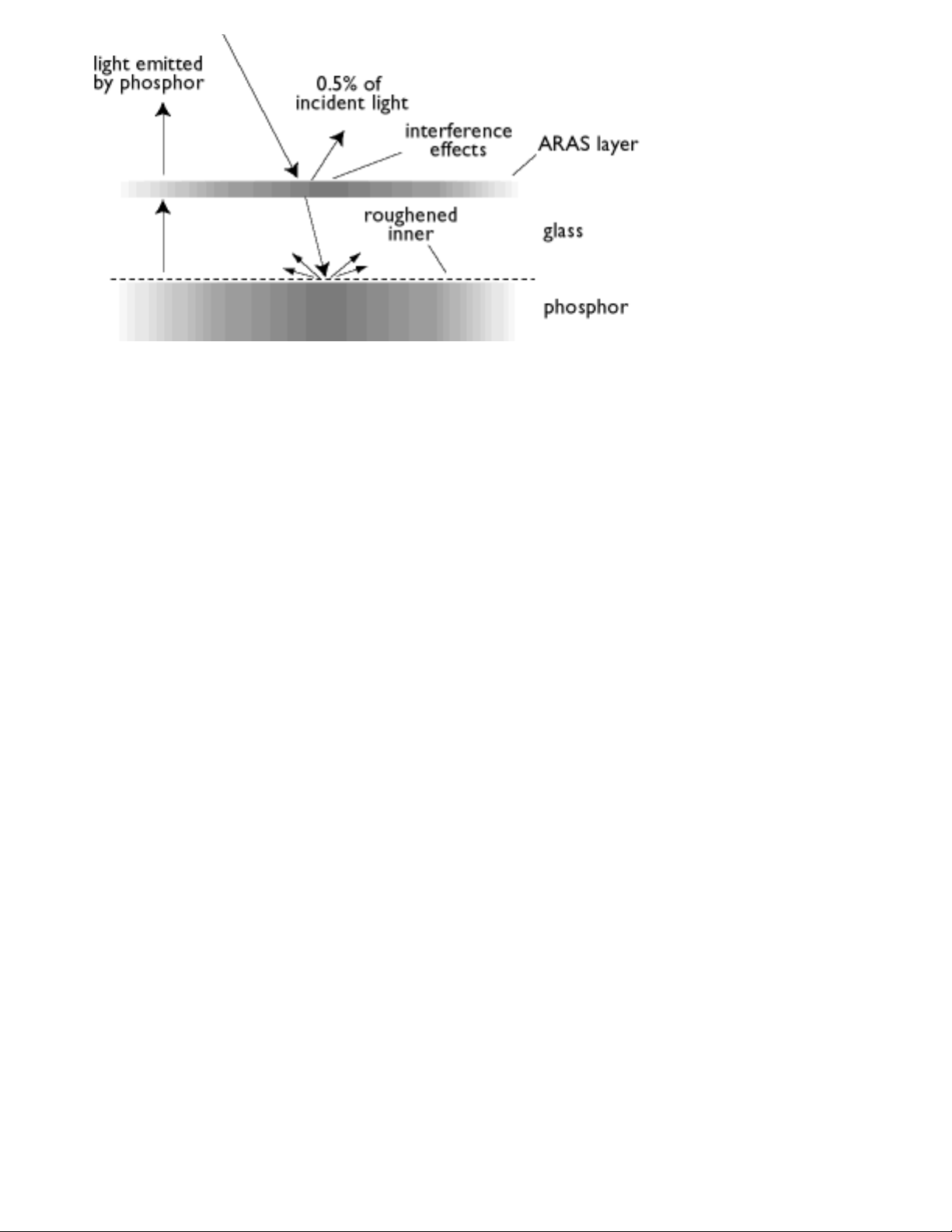
The ARAS coating reflects only about 0.5% of the incident light.
AGRAS (Anti-Glare anti-Reflection Anti-Static) coating.
A combined anti-reflection, anti-glare, anti-static coating.
Self-test function
A monitor equipped with hardware or software to automatically detect cable connection status.
Shape
Deviation of a reproduced picture from its intended shape. The following types of distortion are most
common:
Glossary
file:///G|/manual/english/201P/glossary/glossary.htm (13 of 18) [10/16/1999 6:36:13 AM]

SOG (Synchronization On Green)
A properly functioning color monitor requires five kinds of signals: horizontal sync pulse, vertical sync pulse,
red color signal, green color signal and blue color signal. Signals from a PC are transmitted to a monitor
using one of three methods:
1. Separate sync: Horizontal and Vertical sync signals transmitted separately
2. Composite sync: Horizontal and vertical sync pulses mixed into a single signal train.
3. SOG: Horizontal and vertical sync pulses mixed, then combined with the green color signal.
RETURN TO TOP OF THE PAGE
T
TCO
See Electromagnetic radiation standards.
Tilt function
Glossary
file:///G|/manual/english/201P/glossary/glossary.htm (14 of 18) [10/16/1999 6:36:13 AM]
 Loading...