

Philips 200BW8ES/00, 200BW8EB/27, 200BW8EB/00, 200BW8EB/69, 200BW8EB/75 Service Manual
...
20” TFT LCD COLOR MONITOR
ServiceService
ServiceService
ServiceService
Service Manual
TABLE OF CONTENTS
Description
Important Safety Notice .............................................
Technical Data & Power Management .......................
Connection to PC .......................................................
OSD Menu Control Level Structure ...........................
Advanced OSD Adjustment .......................................
OSD Attention Signal .................................................
Safety and troubleshooting information ....................
Definition of Pixel Defects ..........................................
...........
Wiring Diagram ..........................................................
Mechanical Instructions .............................................
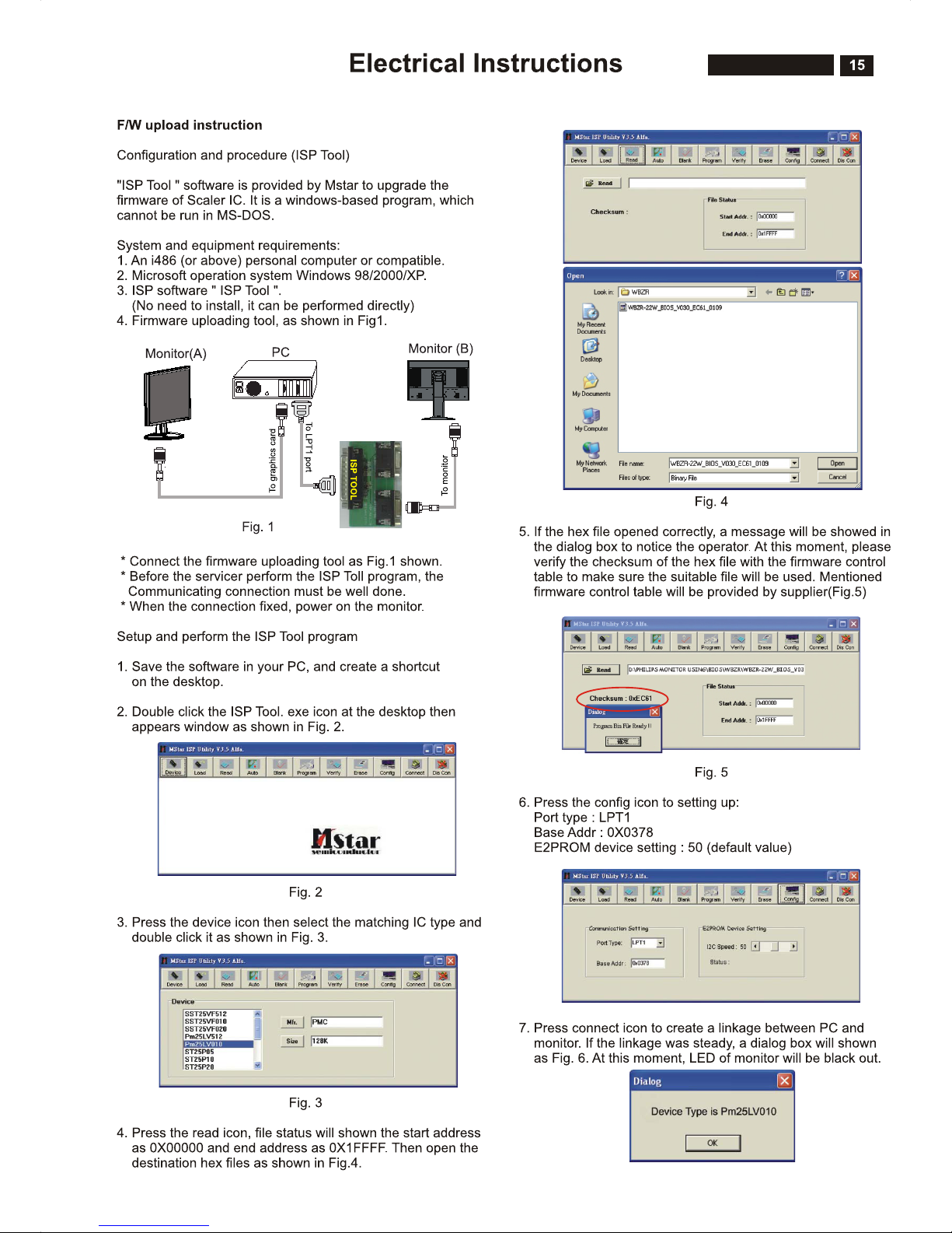
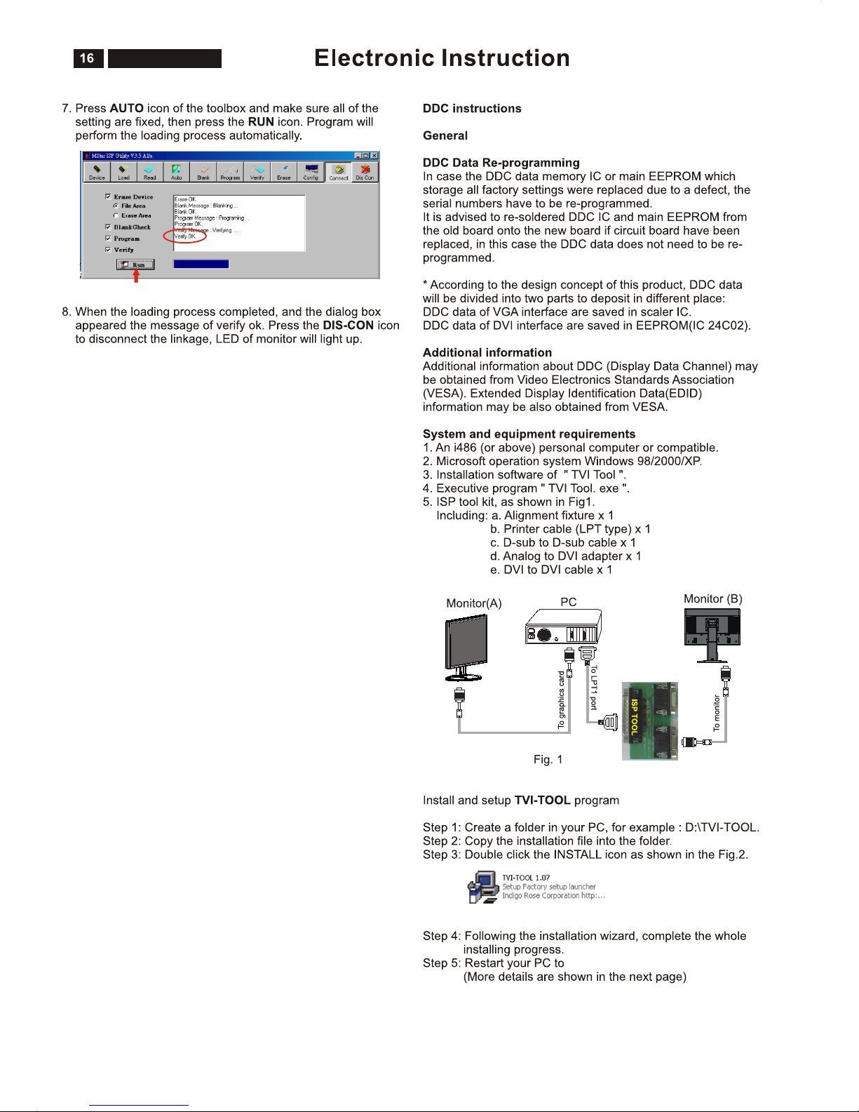
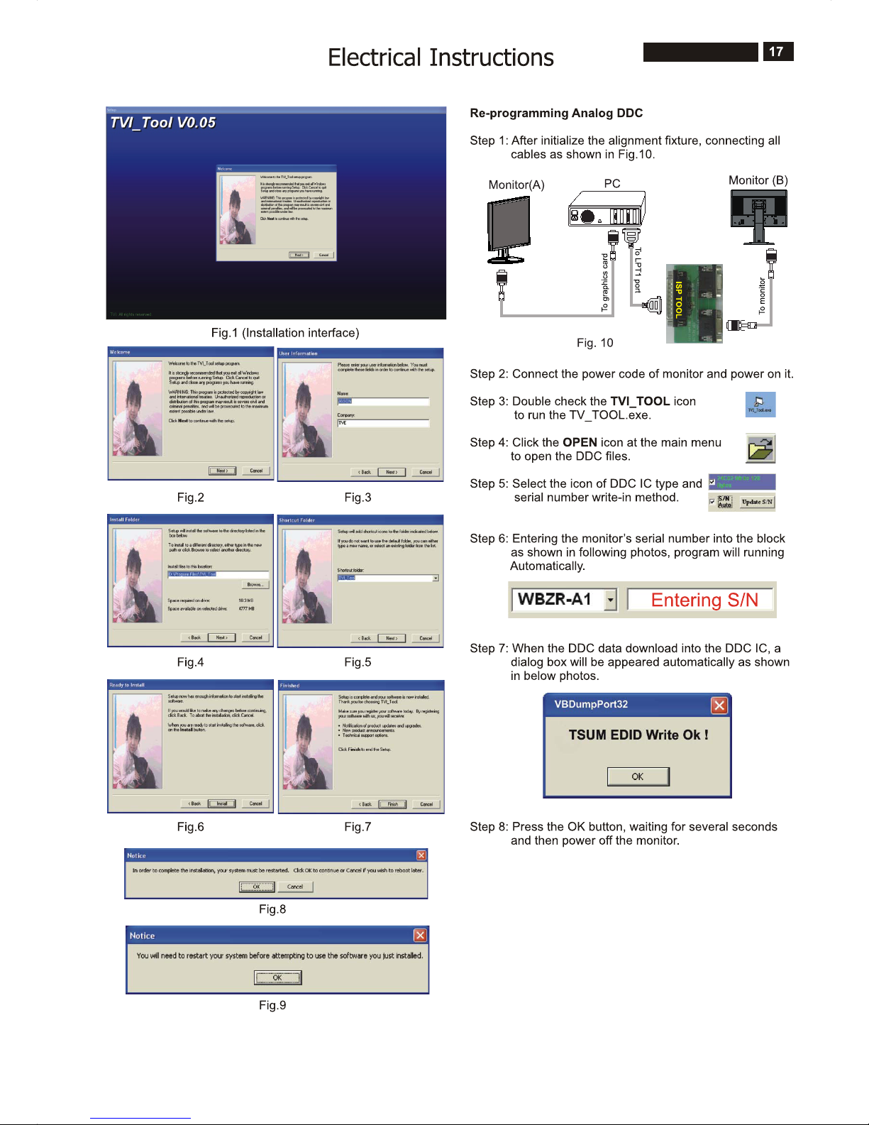
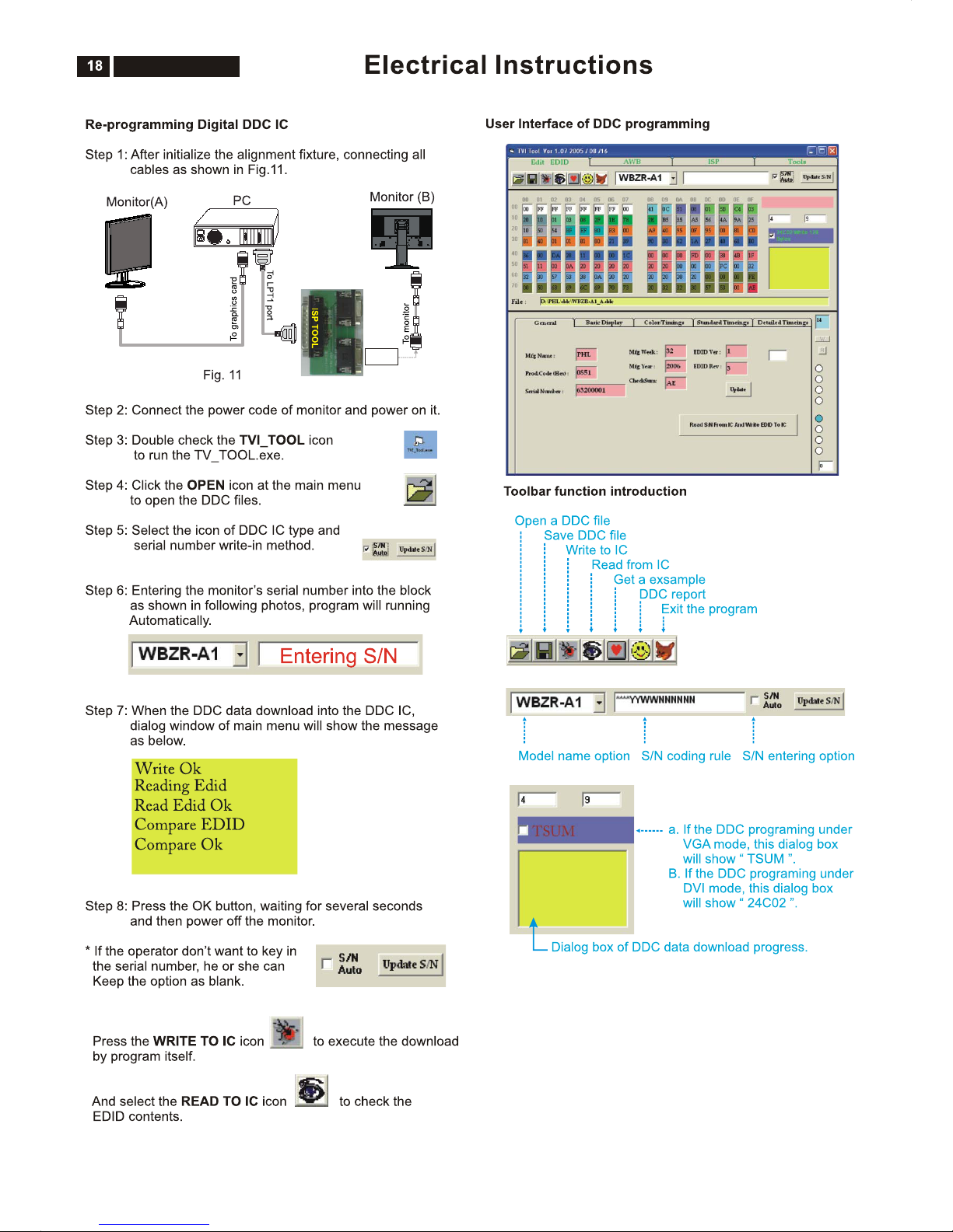
F/W Upload Instructions ............................................
DDC Instructions ........................................................
DDC DATA .................................................................
Safety Instructions, Warnings and Notes ........
Page
2
3~4
5
6
7
8
9
10~11
12
13~14
15~16
17~19
20~21
22
Description
Block Diagram ...........................................................
Scaler Board Schematic Diagram ..............................
Power Board Schematic Diagram ..............................
Button Board Schematic Diagram .............................
Scaler Board Layout Side View .................................
Power Board Layout Side View .................................
Button Board Layout Side View .................................
Exploded View ...........................................................
Recommended Parts List ..........................................
Spare Parts List .........................................................
Different Parts List .....................................................
General Trouble Shooting Guide ...............................
General Product Specification ...................................
Safety Check Process ...............................................
Page
23
24~28
29~30
31
32~33
34~35
36
37
38~49
50~52
52
53~67
68~82
83
SAFETY NOTICE
ANY PERSON ATTEMPTING TO SERVICE THIS CHASSIS MUST FAMILIARIZE HIMSELF WITH THE CHASSIS
AND BE AWARE OF THE NECESSARY SAFETY PRECAUTIONS TO BE USED WHEN SERVICING ELECTRONIC
EQUIPMENT CONTAINING HIGH VOLTAGES.
CAUTION: USE A SEPARATE ISOLATION TRANSFORMER FOR THIS UNIT WHEN SERVICING.
REFER TO BACK COVER FOR IMPORTANT SAFETY GUIDELINE.
Subject to modification
Oct. 23th. 2007
EN :
200BW8ES/00
200BW8EB/27
200BW8EB/69
200BW8EB/75
200BW8EB/93
200BW8EB/00

2
200BW8 LCD
Proper service and repair is important to the safe, reliable
operation of all Philips Consumer Electronics Company**
Equipment. The service procedures recommended by Philips
and described in this service manual are effective methods of
performing service operations. Some of these service
operations require the use of tools specially designed for the
purpose. The special tools should be used when and as
recommended.
It is important to note that this manual contains various
CAUTIONS and NOTICES which should be carefully read in
order to minimize the risk of personal injury to service
personnel. The possibility exists that improper service
methods may damage the equipment. It is also important to
understand that these CAUTIONS and NOTICES ARE NOT
EXHAUSTIVE. Philips could not possibly know, evaluate and
advise the service trade of all conceivable ways in which
service might be done or of the possible hazardous
consequences of each way. Consequently, Philips has not
undertaken any such broad evaluation. Accordingly , a
servicer who uses a service procedure or tool which is not
recommended by Philips must first satisfy himself thoroughly
that neither his safety nor the safe operation of the equipment
will be jeopardized by the service method selected.
* * Hereafter throughout this manual, Philips Consumer
Electronics Company will be referred to as Philips.
Critical components having special safety characteristics are
identified with a by the Ref. No.in the parts list and
enclosed within a broken line*
(where several critical components are grouped in one
area) along with the safety symbol on the schematics or
exploded views.
Use of substitute replacement parts which do not have the
same specified safety characteristics may create shock, fire,
or other hazards.
Under no circumstances should the original design be
modified or altered without written permission from Philips.
Philips assumes no liability , express or implied, arising out of
any unauthorized modification of design.
Servicer assumes all liability .
* Broken Line
WARNING
Important Safety Notice
FOR PRODUCTS CONTAINING LASER :
DANGER - In visible laser radiation when open.
AVOID DIRECT EXPOSURE TO BEAM.
CAUTION - Use of controls or adjustments or
performance of procedures other than
those specified herein may result in
hazardous radiation exposure.
CAUTION - The use of optical instruments with this
Product will increase eye hazard.
TO ENSURE THE CONTINUED RELIABILITY OF THIS
PRODUCT, USE ONLY ORIGINAL MANUFACTURER'S
REPLACEMENT PARTS, WHICH ARE LISTED WITH
THEIR PART NUMBERS IN THE PARTS LIST SECTION
OF THIS SERVICE MANUAL.
Take care during handling the LCD module with backlight
unit
- Must mount the module using mounting holes
four corners.
- Do not press on the panel, edge of the frame
electric shock as this will result in damage to the screen.
- Do not scratch or press on the panel with any sharp
such as pencil or pen as this may result in
panel.
- Protect the module from the ESD as it may damage
electronic circuit (C-MOS).
- Make certain that treatment persons body are
through wrist band.
- Do not leave the module in high temperature and in
of high humidity for a long time.
- Avoid contact with water as it may a short circuit
the module.
- If the surface of panel become dirty, please wipe it
a soft material.( Cleaning with a dirty or
damage the panel.)
arranged in
strongly or
objects,
damage to the
the
grounded
areas
within
off with
rough cloth may

200BW8 LCD
Technical Data
3
1. General Specification
AUO M220EW02 V8
1.1 Panel characteristic
Panel source
Screen type
Screen dimensions
Resolution
Outside dimensions
Pixel pitch (mm)
Color pixel arrangement
Display surface
Color depth
Backlight
View angle (CR>10)
Contrast ratio
White luminance
Color gamut
Response time
Active area (mm)
Resolution
Outside dimensions
Pixel pitch (mm)
Color pixel arrangement
Display surface
Color depth
Backlight
Active area (mm)
View angle (CR>10)
Contrast ratio
White luminance
Color gamut
Response time
1.2 Scanning frequencies
Horizontal scan range
Vertical scan range
1.3 Video
Video dot rate
Input impedance
(Analog signal input)
- video
- Sync
CPT CLAA201WA04
: AUO
: CPT CLAA201WA04
: TN+film
: 20 inches (diagonal) 16:10
: 1680 x 1050 (WXGA+)
: 459.4 (W) x 296.4 (H) x 16.6 (D)
: 0.258 x 0.258
: R. G. B. Vertical Stripe
: Hard-coating (3H), Non-glare type
: 16.7M colors
: 4 lamps
: >= 160 for H/V (typical)
:>=1000:1
: >= 300 nits (7.0mA)
:>=72%
:5ms
M201EW02_V8
: 433.44 (H) x 270.90(V)
: 1680 x 1050 (WXGA+)
: 459.4 (W) x 296.4 (H) x 16.6 (D)
: 0.258 x 0.258
: R. G. B. Vertical Stripe
: Hard-coating (3H), Non-glare type
: 16.7M colors
: 4 lamps
: 433.44 (H) x 270.90(V)
: >= 160 for H/V (typical)
:>=1000:1
: >= 300 nits (7.0mA)
:>=72%
:5ms
: 30 - 93 K Hz (automatic)
: 56 - 76 Hz (automatic)
: < 165 M Hz (Over 165MHz,
Warning message will show up)
:75ohm
: 2.2K ohm
: 700 mVpp
: Analog R/G/B separate inputs
Separate horizontal and vertical /
Composite (H+V) TTL level,
Sync On Green (SOG) sync
0.3Vp-p Negative
: Signal TMDS link
(3 channels : Rx0 & Rx1 & RX2-/+)
: Both Analog and Digital input.
It can be switching via OSD option.
: 472.9 mm
: 400.4 mm
: 213.6 mm
: 525 mm
: 174 mm
: 452 mm
: 5.3 Kg (Including I/F cable 240g)
:-5°+2/-0°(forward )
+25°+0/-3°(backward )
: nil
: nil
: nil
:AC90-264V,
:50/60 2Hz
: < 50W maximum, 43W (typ)
:40
: 5 to 35 degree C
: 10% to 85% (max.)
: 0 - 3658 m
: 600 - 1000 mBAR
(Recommend at 5 to 35 degree C,
Humidity less then 60%)
: -20 to 60 degree C
: 95% max
: 0 - 12192 m
: 300 - 1100 mBAR
: 50,000 Hrs
+
:Impedance: 8 ohm
Frequency range: 20 Hz ~ 20 kHz
Output: 1W x 2
: 555 mm
: 190 mm
: 472 mm
0 to degree C
Input signal levels
Sync. input signals
Input impedance (Digital)
Video interface
1.4 Audio
1.5 Physical characteristics
Unit dimensions
- Width
- Height
- Depth
Packed unit dimensions
Weight (monitor only)
Title angel
Swivel angel
Height adjustment
Portrait display
AC input: - voltage
- frequency
Power consumption
Ambient temperature
Operating
- Temperature
- Humidity
- Altitude
- Air pressure
Storage
System MTBF
- Width
- Height
- Depth
Packed unit dimensions
(China only)
- Width
- Height
- Depth
- Temperature
- Humidity
- Altitude
- Air pressure
4
200BW8 LCD
Automatic Power Saving
Data Storage
Factory preset mode:
If you have VESA / DPMS compliance display card or software
installed in your PC, the monitor can automatically reduce
power consumption when power saving function active. And if
an input from keyboard, mouse or other devices is detected,
the monitor will automatically wake up. The following table
shows the power consumption and signaling of this automatic
power saving feature:
This monitor must comply with the Microsoft On Now
specification, with two power management states, as defined
by the VESA DPMS document. And must appropriately display
the DPMS states. Also comply with Environmental Protection
Agency (EPA) Energy Star and TCO03 power management
standard strictly.
ENERGY STAR is a U.S. Registered mark. AS AN ENERGY
STAR PARTNER, PHILIPS HAS DETERMINED THAT THIS
PRODUCT MEETS THE ENERGY STAR GUIDELINES OF
ENERGY EFFICIENCY.
This monitor has 18 factory-preset modes as indicated in the
following table:
Technical Data
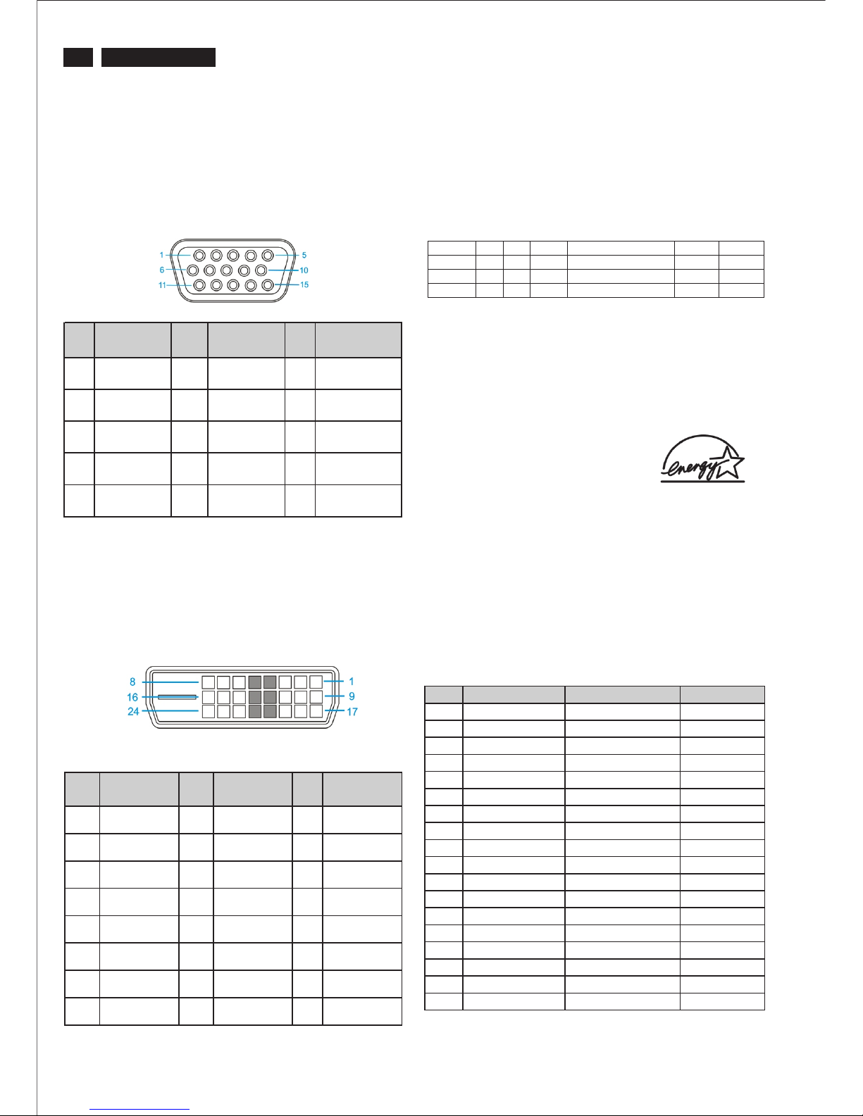
2. Pin Assignment
2.1 PC analog video input with D - sub connector.
Connector type of analog signal cable :
D - Sub male with DDC2B pin assignment.
Blue connector with thumb-operated jackscrews.
Pin assignment :
2.2 PC digital video input with DVI-D connector.
Connector type of DVI-D signal cable :
DVI-D male with DDC2B pin assignment.
White connector with thumb-operated jackscrews.
Pin assignment :
Mode HSYNC VSYNC Video Pwr-cons. Indication Rec. time
Power-O n On On acti ve < 50W ( <54W : for audio mod el) Green LED --
Off Off O ff blan ked < 1 W Amber LED < 5 s
DC Power Off N/A < 1 W LED Off
PIN
No.
Signal
Assignment
PIN
No.
Signal
Assignment
PIN
No.
Signal
Assignment
1 Red 6 Red GND 11 Sense (GND)
2 Green/ SOG 7 Green GND 12 Bi-directional
data
3 Blue 8 Blue GND 13 H/H+V sync
4 Sense (GND) 9 DDC +3.3V or
+5V
14 V-sync
5 N/A 10 Logic GND 15 Data clock
PIN
No.
Signal
Assignment
PIN
No.
Signal
Assignment
PIN
No.
Signal
Assignment
1 T.M.D.S.
data2-
9 T.M.D.S.
data1-
17 T.M.D.S.
data0-
2 T.M.D.S.
data2+
10 T.M.D.S.
data1+
18 T.M.D.S.
data0+
3 T.M.D.S.
data2 shield
11 T.M.D.S.
data1 shield
19 T.M.D.S.
data0 shield
4 No Connect 12 No Connect 20 No Connect
5 No Connect 13 No Connect 21 No Connect
6 DDC clock 14 +5V Power 22 T.M.D.S clock
shield
7 DDC data 15 Ground (for
+5V)
23 T.M.D.S.
clock+
8 No Connect 16 Hot plug
detect
24 T.M.D.S. clock-
Item Resolution H. freq/ V. freq Standard
1 640*350 31.469 KHz/70.086 Hz
IBM VGA 10H
2 720*400 31.469 KHz/70.087 Hz
IBM VGA 3H
3 640*480 31.469 KHz/59.94 Hz
IBM VGA 12H
4 640*480 35 KHz/67 Hz
MACINTOSH
5 640*480 37.5 KHz/75 Hz
VESA
6 800*600 35.0156 KHz/56.25 Hz
VESA
7 800*600 37.879 KHz/60.317 Hz
VESA
8 800*600 46.875 KHz/75 Hz
VESA
9 1024*768 48.363 KHz/60.004 Hz
VESA
10 1024*768 60.023 KHz/75.029
VESA
11 1280*1024 63.981 KHz/60.02 Hz
VESA
12 1280*1024 79.976 KHz/75.025 Hz
VESA
13 1440*900 55.469 KHz/59.901 Hz
VESA
14 1440*900 55.935 KHz/59.887
VESA
15 1440*900 70.635 KHz/74.984 Hz
VESA
16 1920*1080 66.587 KHz/60 Hz
CVT 2.3 MA-R
17 1680*1050 65.29 KHz/60 Hz
CVT 1.76 MW
18 1680*1050 65.29 KHz/60 Hz
CVT 1.76 MW -R
200BW8 LCD
Connection to PC
5
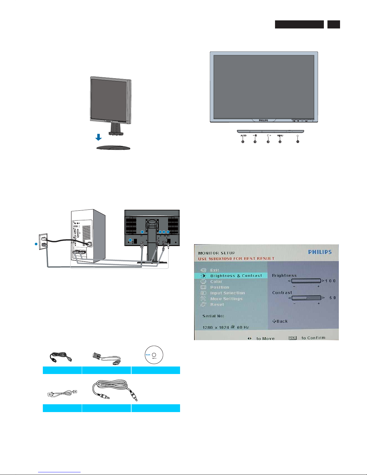
1. Connection to PC
c. Accessory Pack
Please follow the steps to connect your LCD Monitor to PC.
a. Assembly LCD Monitor with base
b. Connect to PC
1). Turn off your computer and unplug its power cable.
2). Connect the monitor signal cable to the video connector
on the back of your computer.
3). Plug the power cord of your computer and your monitor
Into a nearby outlet.
4). Turn on your computer and monitor. If the monitor
displays an image, installation is complete.
Port definition:
(1) AC power input
(2) DVI-D input
(3) VGA input
(4) Kensington anti-thief lock
(5) PC audio input
Set your Monitor at 1680*1050@60Hz for best performance.
It is also strongly recommended to use DVI input(may require
the optional DVI cable) for the ture digital enjoyment.
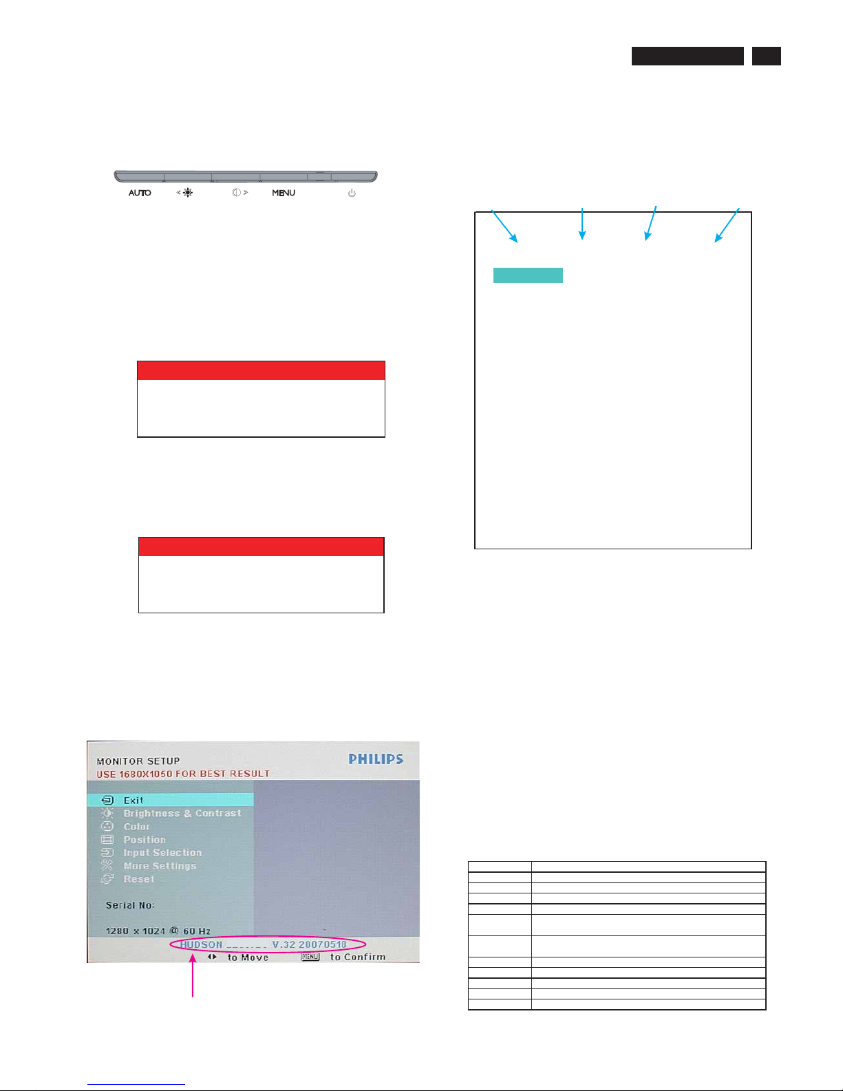
2. Function key definition
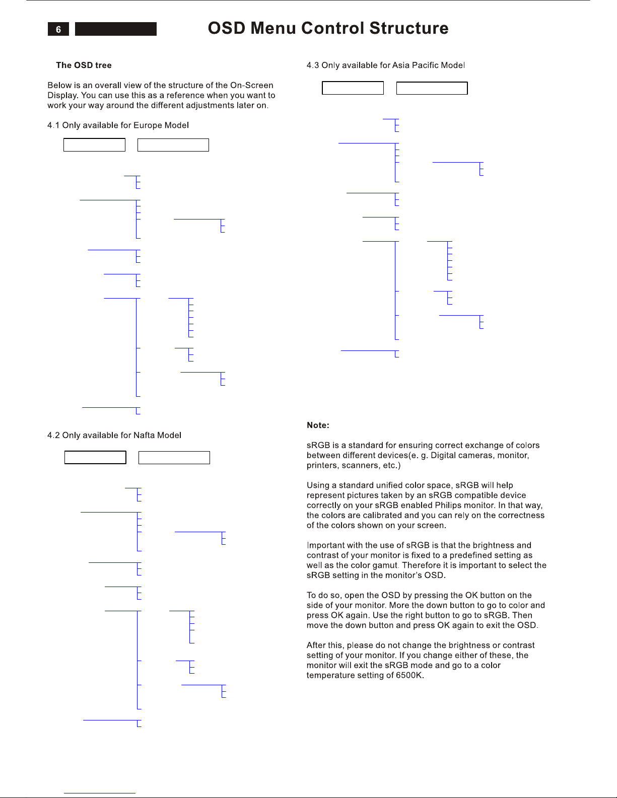
3. Description of the On Screen Display
<>
MENU
(1) To switch monitor’s power on and off
(2) To access OSD menu
(3) Hot key of contrast adjustment and to adjust OSD
value up when OSD menu is active
(4) Hot key of brightness adjustment and to adjust OSD
Value down when OSD menu is active
(5) Automatically adjust the horizontal position, vertical
position, phase and clock settings
On-Screen Display(OSD) is a feature in all Philips LCD
monitors. It allows and end user to adjust screen performance
or select functions of the monitors directly through an on-screen
instruction window. A user friendly on screen display interface is
shown as below:
Basic and simple instruction on the control keys.
According to the above OSD structure, users can :
press or buttons to move the cursor,
press button to confirm the choice or change,
press button to adjust the value,<>
MENU
AUTO
or
press button to save the changes.
press button to automatically adjust the horizontal
position, vertical position, phase and clock setting.
200BW
4
1
32
5
1
Power cord VGA cable EDFU CD
DVI cable (Optional)
Audio cable
Brightness & Contrast Brightness
Color
Position
Input selection
More Settings
Main Menu (1st Level)
Sub Menu (2nd Level)
Contrast
Back
9300K
Original Color
6500K
User Define
Back
Red
Green
Blue
Exit
Horizontal
Vertical
Back
Analog
Digital
Back
Language English
Français
Deutsch
Italiano
Back
Phase/Clock Phase
Clock
Back
OSD Settings Horizontal
Vertical
Back
Back
oNteseR
Yes
Español
Русский
Brightness & Contrast Brightness
Color
Position
Input selection
More Settings
Main Menu (1st Level)
Sub Menu (2nd Level)
Contrast
Back
9300K
Original Color
6500K
User Define
Back
Red
Green
Blue
Exit
Horizontal
Vertical
Back
Analog
Digital
Back
Language English
Français
Portugues
Back
Phase/Clock Phase
Clock
Back
OSD Settings Horizontal
Vertical
Back
Back
oNteseR
Yes
Español
中文
Brightness & Contrast Brightness
Color
Position
Input selection
More Settings
Main Menu (1st Level)
Sub Menu (2nd Level)
Contrast
Back
9300K
Original Color
6500K
User Define
Back
Red
Green
Blue
Exit
Horizontal
Vertical
Back
Analog
Digital
Back
Language English
Français
Deutsch
Italiano
Phase/Clock Phase
Clock
Back
OSD Settings Horizontal
Vertical
Back
Back
oNteseR
Yes
Español
中文
Back
60
4.
200BW8 LCD
200BW8 LCD
Advanced OSD Adjustment
7
Advanced OSD Adjustment
MENU
MENU
MENU
1. Front control panel
2. To Lock/Unlock OSD function
The OSD function can be locked by pressing button
for more than 10 seconds, the screen shows following
windows for 3 seconds.
Every time when you press any button, this message
appears on the screen automatically.
Locked OSD function can be released by pressing
button for more than 10 seconds. While press button
for OSD unlocked purpose, the screen will keep showing
OSD MAIN MENU LOCKED until OSD function unlocked and
screen automatically shows following window for 3 seconds.
3. Access Factory Mode
To hold and buttons, you can saw the LED
light flashing at this time. Then release the button and
Keep pressing the button. The monitor will power on
and LED light give out orange light. Press to bring up
OSD menu for confirmation as below:
If this message appeared, means monitor already entered
the factory mode.
AUTO POWER
AUTO
POWER
MENU
4. Entering Burn-in mode and others
If you access into factory mode, press or button to move
the cursor on the message bar of “ HUSDON 200BW8 V.32”.
Then press to confirm, OSD menu will convert into
another format as below:
Move the cursor by button, and press the
to change the burn-in mode from Off to ON.
Leave factory mode by simply power off the monitor.
* If you only want to enter burn in mode, please don’t change
any other setting items as above listed.
* Unfortunately, if some settings has been changed by
unknown reasons or wrong operation. Please refer to the
chapter of “W/B Adjustment” to guide the operator how to
restore the default settings or do adjustment.
Appendix:
Explanation of above listed selections.
<>
MENU
MENU
Warning
or
button
<>
BIOS Revision Scaler IC Type Panel Type BIOS issued date
ATTENTION
OSD MAIN CONTROLS LOCKED
ATTENTION
OSD MAIN CONTROLS UNLOCKED
Selection Description
Burn in On/Off Enter Aging Mode
Auto Color Auto Color Adjustment
Con Contrast Adjustment
Bri Brightness Adjustment
Gain
ADC Gain Value Adjustment
(Auto adjustment by H/W when implement Auto Color function)
Offset
ADC Offset Value Adjustment
(Auto adjustment by H/W when implement Auto Color function)
sRGB sRGB Color Temperature Gain Value Adjustment
9300K 9300K Color Temperature Gain Value Adjustment
6500K 6500K Color Temperature Gain Value Adjustment
Color Update Save All of Color Temperature Gain Value
Factory Reset Memory Recall to Factory Default Settings
V.32 05/18/07
Off
Con 50
Bri 100
Gain R 88 G 91 B 88
Offset R 121 G 131 B 131
sRGB R 97 G 98 B 82
9300K R 91 G 94 B 95
6500K R 97 G 98 B 82
CLAA201WA04TSUMU58WHJ
Fatory Reset
Color Update
AutoColor
Burn in
200BW8
8
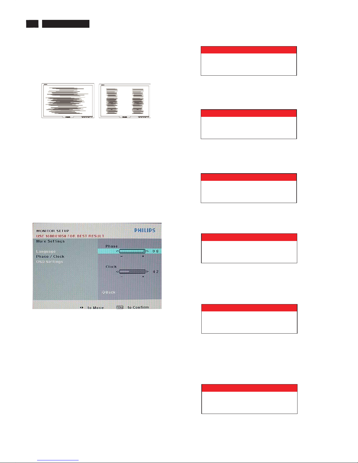
Clock & Phase Adjustment
MENU
More Settings
MENU
Clock Phase
Phase
Clock
MENU
OSD Attention signal
1. NO VIDEO INPUT
Due to the different quality of video signal generated from
graphics cards. It is necessary to adjust CLOCK and PHASE
functions for the optimal video display of LCD monitor. So
maybe some flicker appeared as Fig.1 & 2.
Fig.1 Fig.2
Following steps will guide you to make correct adjustment of
CLOCK and PHASE:
a. Restart your computer.
b. Press to bring up OSD menu after the OS
(Operation System) boot up.
c. Press or to select the option of and
then
press to bring up its submenu as shown in Fig.3.
d. Select the or adjustment items in submenu
and press or to adjust.
(If the phenomenon as Fig.1, you should adjust “ ”)
(If the phenomenon as Fig.2, you should adjust “ ”)
e. Quit OSD by press button to save the settings.
Fig.3
However, CLOCK and PHASE functions are only available
while analog video signal is supplied. Operating unit under
digital signal state, the video clock information can be
obtained from graphics cards directly. Therefor, it is
unnecessary to adjust these functions.
The monitor will detect various display situation
automatically. When the monitor detects the problems, the
screen will show the different warning signals to remind you
what is happen to your monitor.
This screen appears if there is no video signal input. Please
check that the signal cable is properly connected to the video
cardofPCandmakesurePCison.
<>
<>
OSD Attention Signals
2. CANNOT DISPLAY THIS VIDEO MODE
3. ENTERING SLEEP MODE
4. WAIT FOR AUTOMATIC ADJUSTMENT
AUTO
5. USE 1680*1050 FOR BEST RESULT
6. SELECTED INPUT NOT AVAILABLE
This screen warns then the input frequency from the
computer is not a standard video mode or out of the monitor’s
scanning range. Please change the display results.
This screen appears when the monitor is about to enter the
sleep mode. Please press any key on the keyboard or click
the mouse to wake up the monitor and computer.
This screen appears when you touch the button. It will
disappear when the monitor is properly adjusted.
This message appears at the top of the OSD window when
the video mode input is not the recommended 1680*1050.
Other modes may result in some picture distortion. Please
adjust the video mode to 1680*1050 at 60Hz for best display
quality.
When you select video input between analog or digital signal
via INPUT SELECTION function of OSD menu, if the one you
are selecting is not available, following message will appear
on the screen then switching back to the previous setting
automatically.
ATTENTION
NO VIDEO INPUT
ATTENTION
CANNOT DISPLAY THIS VIDEO
MODE, CHANGE COMPUTER DISPLAY
INPUT TO 1680X1050 @60HZ
ATTENTION
ENTERING SLEEPING MODE
ATTENTION
USE 1680 X 1050 FOR BEST RESULT
ATTENTION
WAITING FOR AUTOMATIC ADJUSTMENT
ATTENTION
SELECTED INPUT NOT AVAILABLE
200BW8 LCD
200BW8 LCD
200BW8 LCD
200BW8 LCD
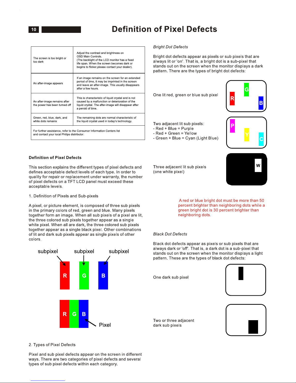
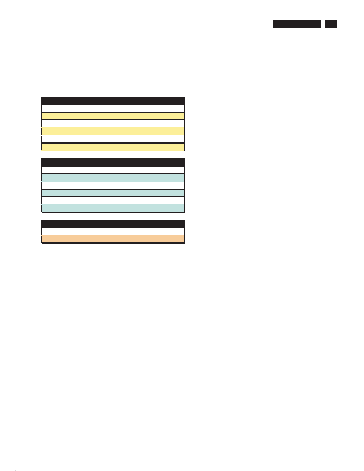
Definition of pixel defects
11
3. Proximity of Pixel Defects
Because pixel and sub pixels defects of the same type that
are near to one another may be more noticeable, Philips also
specifies tolerances for the proximity of pixel defects.
Perfect Panel - ISO 13406-2 Class II compliant do-defectfree-display.
BRIGHT DOT DEFECTS ACCEPTABLE LEVEL
MODEL 200BW8
1 lit subpix el 3
2 adjacent li t subpixels 1
3 adjacent li t subpixels (one white pixel) 0
Distance between two bright dot defects* 15 mm
Total bright dot defects of all types 3
BLACK DOT DEFECT S ACCEPTABLE LEVEL
MODEL 200BW8
1 dark subpixel 5
2 adjacent dark subpixels 2
3 adjacent dark subpixels 0
Distance between two black dot defects* 15 mm
Total black dot defects of all types 5
TOTAL DOT DEFECTS ACCEPTABLE LEVEL
MODEL 200BW8
Total bright or black dot def ects of all types 5
Note:
* 1 or 2 adjacent sub pixel def ects = 1 dot defect
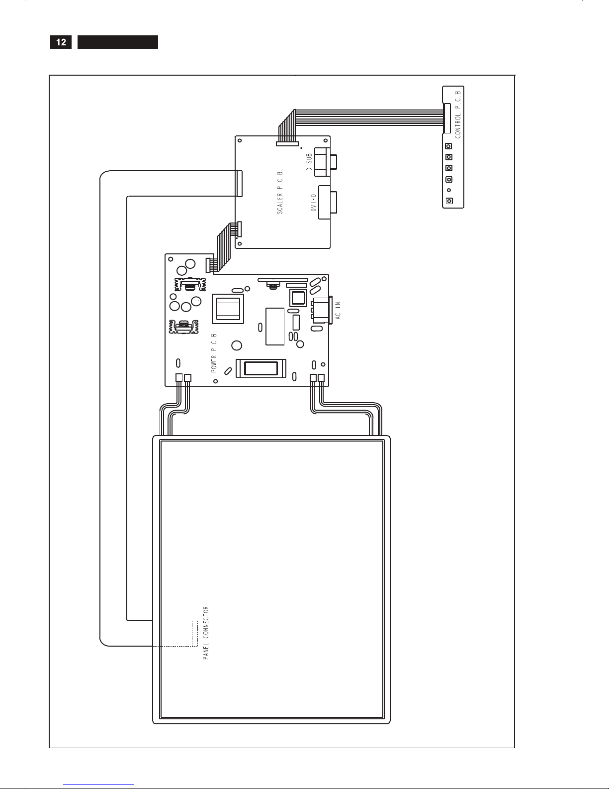
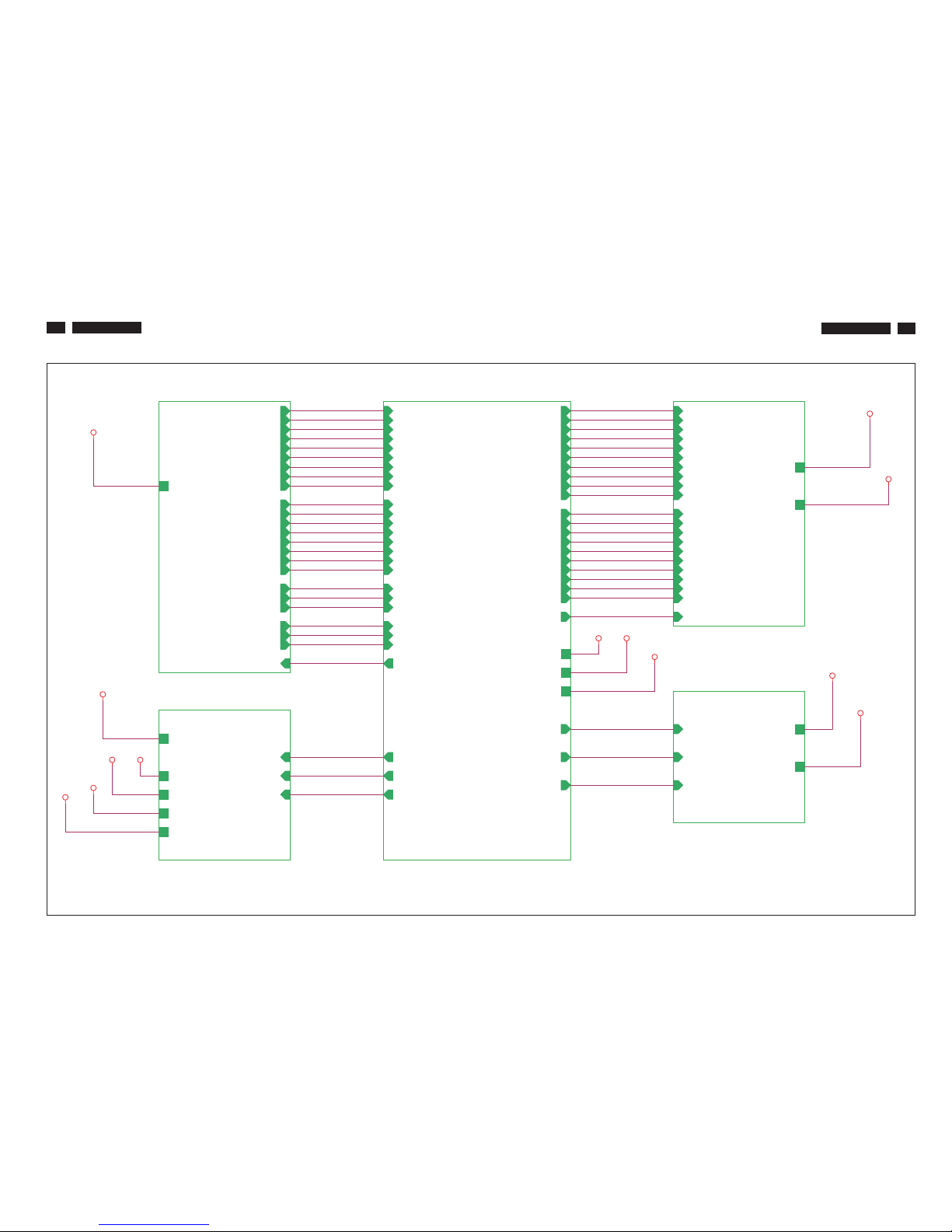
Wiring Diagram
CN2
1
2
29
30
CN78 1
CN3
CN4
CN1
7
8
1
2
CN101
CN1
CN2
CN3
CN4
CON1
1
8
200BW8 LCD
200BW8 LCD
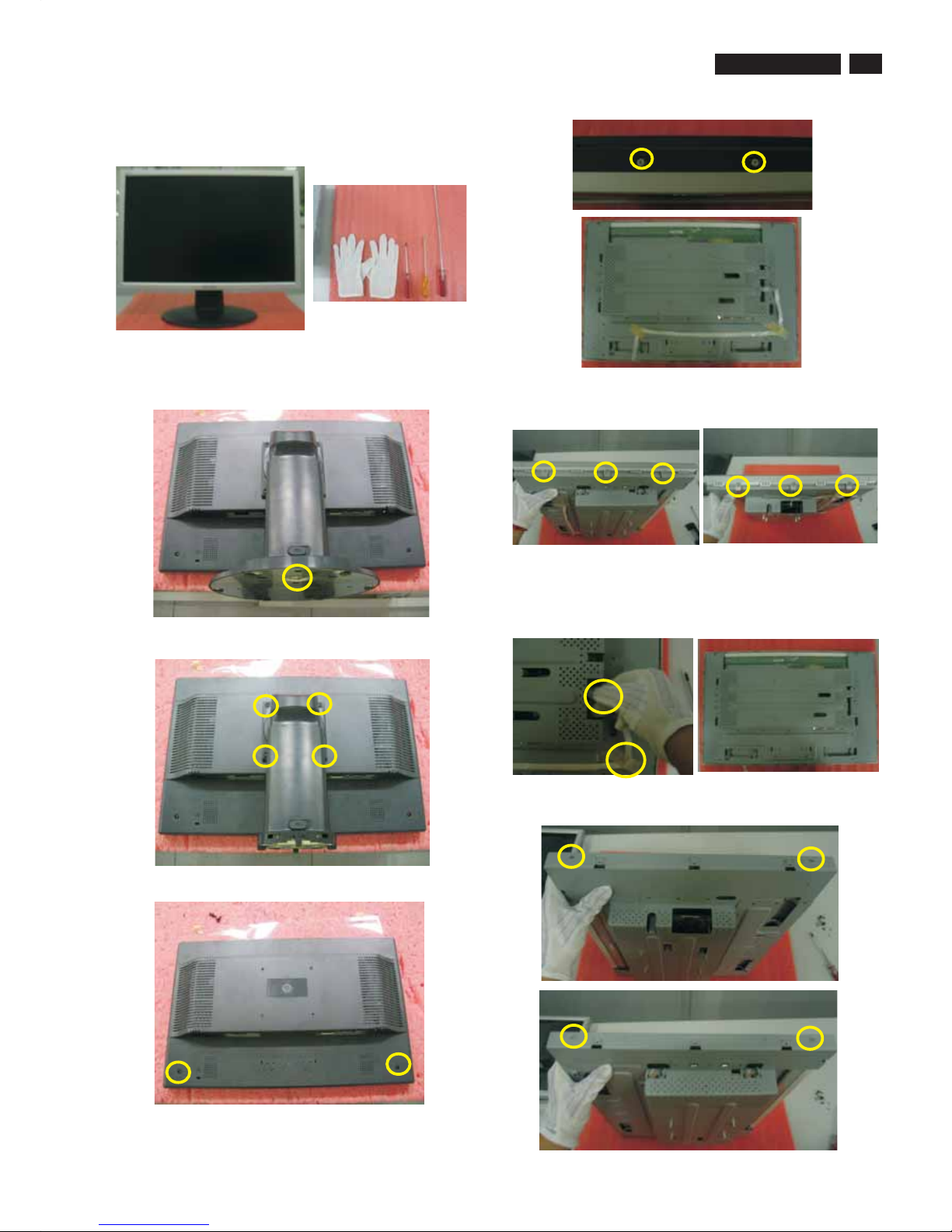
Mechnical instructions
13
1. Stand up the monitor on the electrostatic cushion, then
wear your gloves, all tools (screwdriver, both with small and
big one) prepared.
2. Put down the monitor softly, remove 1pcs screw from
bottom of base and take off it.(note: care of the panel without
scraped.)
3. Release 4pcs screws from stand and take off it.
4. Release the two screws from rear cover.
5. Release the two screws on the underside of rear cover,
then take out rear cover.
6. Release the three screws on the left side of bezel, then
release the other three screws on the right of bezel.
7. Tear off the adhesive tape and take out the cable from the
sink of main board(note: don’tdoitforcibly).
8. Release the two screws on the left side of shielding, then
release the other two screws on the right side of shielding.
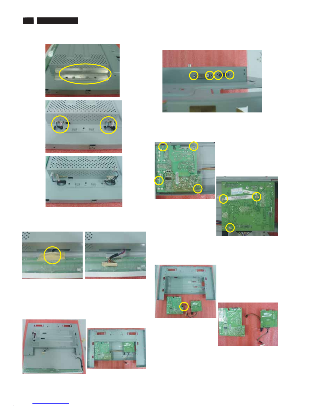
14
200BW8 LCD
Mechnical instructions
9. Take out the lamp cable shielding and undo the lamp cable.
10. Tear off the adhesive tape and undo the LVDS cable.
11. Separate the panel and shielding
12. Release the four hexagonal screws.
13. Take out the protect film and release the four screws from
power board, then release the three screws from the main
board.
14. Separate the connect cable between main board and
power board, then take out the connect cable from main
board.(note: be careful of the jack, don’t do it forcibly.)
200BW8 LCD
200BW8 LCD
200BW8 LCD
200BW8 LCD
200BW8 LCD
19
Electronic Instruction
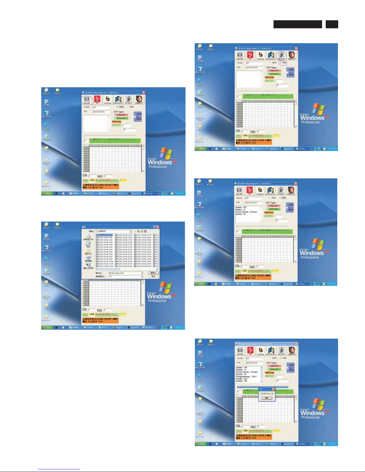
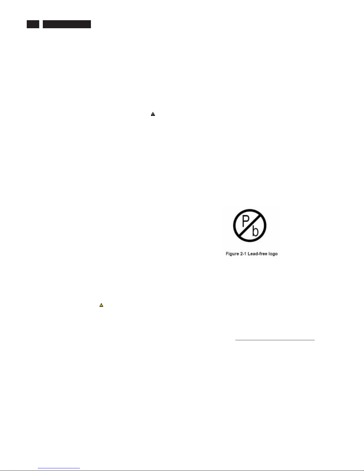
Re-programming of writing HDCP KEY
Step 1: Please install the software of isp HDCP key Version1.13
,the tool is the same with isping EDID.
Step 2: Opening the software.
Step 3: Pressing the button of “OPEN FILE”, as follows:
Step 4: Choosing the HDCP KEY that you save:
button of ”ISP HDCP”.
Step 5: If the Flash Rom of monitor is 2MB, please
choose”3F000”,but if it is 1MB please choose 1F000(if you
choose amiss ,the monitor maybe shut down) ,then press
the
Step 6: The software will write HDCP KEY into monitor.
Step 7: If the software write HDCP KEY into monitor
successfully ,the message will be display ,as follow , if the
software write HDCP KEY into monitor unsuccessfully
,please check the cable ,and restart from step5 .

20
200BW8 LCD
DDC DATA
THE DISPLAY DATA CHANNEL (DDC_2B) CONTENT INCLUDING:
(Analog mode)
------------------------------------------------------------------------------------EDID data ( 128 bytes )
-----------------------------------------------------------------------------------012 345 6789
----------------------------------------------------------------------
0|00FFFFFFFFFFFF00410C
10|650801 010101 08110103
20|082F1E782E93 45A3554A
30|98271550 54BFEF00B300
40|A940950F 950081C08140
50|714F8180 21399030621A
60|274068B0 3600DA281100
70|001C0000 00FF00434A31
80|30373038 313233343536
90|000000FC005068696C69
100|70732032 303042570000
110 | 00 FD 00 38 4C 1E 53 11 70 0A
120|20323030 57530024
___________________________________________________
(08-09) ID Manufacturer Name = PHL
(10-11) Product ID Code (Non-Alphanumerical) = 0865 - (2149)
(12-15) Last 5 Digits of Serial Number = NOT SPECIFIED
(16) Week of Manufacture = 08
(17) Year of Manufacture = 2007
(10-17) Complete Serial Number = NOT SPECIFIED
(18) EDID Structure Version Number = 1
(19) EDID Structure Revision Number = 3
(20) VIDEO INPUT DEFINITION : = Separate Sync,
Analog signal, 0.700V/0.300V (1.000 Vp-p)
(21) Maximum Horizontal Image Size = 470mm
(22) Maximum Vertical Image Size = 300mm
(23) Display Gamma = 2.20
(24) DPMS Supported Feature: = Active Off.
Display type = RGB color display
(25-34) CHROMA INFO:
Red x = 0.639 Green x = 0.289
Blue x = 0.153 White x = 0.313
Red y = 0.333 Green y = 0.597
Blue y = 0.082 White y = 0.329
(35) ESTABLISHED TIMING I:
720 x 400 @ 70Hz (VGA, IBM)
640 x 480 @ 60Hz (VESA)
640 x 480 @ 67Hz (MAC II, Apple)
640 x 480 @ 72Hz (VESA)
640 x 480 @ 75Hz (VESA)
800 x 600 @ 56Hz (VESA)
800 x 600 @ 60Hz (VESA)
(36) ESTABLISHED TIMING II:
800 x 600 @ 72Hz (VESA)
800 x 600 @ 75Hz (VESA)
832 x 624 @ 75Hz (MAC II, Apple)
1024 x 768 @ 60Hz (VESA)
1024 x 768 @ 70Hz (VESA)
1024 x 768 @ 75Hz (VESA)
1280 x 1024 @ 75Hz (VESA)
(37) Manufacturer's Reserved Timing:
None specified.-
DDC Data
(38-53) Standard Timing Identification:
#1: 1680 x 1050 @ 60Hz
#2: 1600 x 1200 @ 60Hz
#3: 1440 x 900 @ 75Hz
#4: 1440 x 900 @ 60Hz
#5: 1280 x 720 @ 60Hz
#6: 1280 x 960 @ 60Hz
#7: 1152 x 864 @ 75Hz
#8: 1280 x 1024 @ 60Hz
(54-71) Detail Timing Description #1:
1680x1050 Pixel Clock=146.2MHz
-------------------------------------------------------------------------------Horizontal Image Size=474mm
Vertical Image Size=296mm
Refresh Mode:
Non-Interlaced Normal display, no stereo
HORIZONTAL:
Active Time = 1680 pixels
Blanking Time = 560 pixels
Sync Offset = 104 pixels
Sync Pulse Width = 176 pixels
Border = 0 pixels
Frequency = 65.3 kHz
VERTICAL:
Active Time = 1050 lines
Blanking Time = 39 lines
Sync Offset = 3 lines
Sync Pulse Width = 6 lines
Border = 0 lines
Frequency = 60.0 Hz
Sync configuration: Digital separate, V(+), H(-)
(72-89) Monitor Description:
--------------------------------------------------------------------------------
Monitor S/N: CJ10708123456
(90-107) Monitor Description:
--------------------------------------------------------------------------------
Monitor Name: Philips 200BW
(108-125) Monitor Description:
--------------------------------------------------------------------------------
Monitor Range Limits:
Vertical Frequency (min) = 56Hz
Vertical Frequency (max) = 76Hz
Horizontal Frequency (min) = 30KHz
Horizontal Frequency (max) = 83KHz
Maximum Supported Pixel Clock = 170MHz
(127) Checksum OK.

200BW8 LCD
DDC Data
21
DDC DATA
THE DISPLAY DATA CHANNEL (DDC_2B) CONTENT INCLUDING:
(Digital mode)
------------------------------------------------------------------------------------EDID data ( 128 bytes )
------------------------------------------------------------------------------------012 345 6789
----------------------------------------------------------------------
0|00FFFFFFFFFFFF00410C
10|650801 0101 0108110103
20|802F1E782E 9345A3554A
30|98271550 54 BFEF00B300
40|A940950F95 0081C08140
50|714F81807C 2E90A0601A
60|1E40302036 00B20E1100
70|001C000000 FF00434A31
80|3037303831 32 33343536
90|000000FC0050 68696C69
100|7073203230 30 42570000
110 | 00 FD 00 38 4C 1E 53 11 70 0A
120|2032303057 530001
___________________________________________________
(08-09) ID Manufacturer Name = PHL
(10-11) Product ID Code (Non-Alphanumerical) = 0865 - (2149)
(12-15) Last 5 Digits of Serial Number = NOT SPECIFIED
(16) Week of Manufacture = 08
(17) Year of Manufacture = 2007
(10-17) Complete Serial Number = NOT SPECIFIED
(18) EDID Structure Version Number = 1
(19) EDID Structure Revision Number = 3
(20) VIDEO INPUT DEFINITION : =
Digital signal, 0.700V/0.300V (1.000 Vp-p)
(21) Maximum Horizontal Image Size = 470mm
(22) Maximum Vertical Image Size = 300mm
(23) Display Gamma = 2.20
(24) DPMS Supported Feature: = Active Off.
Display type = RGB color display
(25-34) CHROMA INFO:
Red x = 0.639 Green x = 0.289
Blue x = 0.153 White x = 0.313
Red y = 0.333 Green y = 0.597
Blue y = 0.082 White y = 0.329
(35) ESTABLISHED TIMING I:
720 x 400 @ 70Hz (VGA, IBM)
640 x 480 @ 60Hz (VESA)
640 x 480 @ 67Hz (MAC II, Apple)
640 x 480 @ 72Hz (VESA)
640 x 480 @ 75Hz (VESA)
800 x 600 @ 56Hz (VESA)
800 x 600 @ 60Hz (VESA)
(36) ESTABLISHED TIMING II:
800 x 600 @ 72Hz (VESA)
800 x 600 @ 75Hz (VESA)
832 x 624 @ 75Hz (MAC II, Apple)
1024 x 768 @ 60Hz (VESA)
1024 x 768 @ 70Hz (VESA)
1024 x 768 @ 75Hz (VESA)
1280 x 1024 @ 75Hz (VESA)
(37) Manufacturer's Reserved Timing:
None specified.
(38-53) Standard Timing Identification:
#1: 1680 x 1050 @ 60Hz
#2: 1600 x 1200 @ 60Hz
#3: 1440 x 900 @ 75Hz
#4: 1440 x 900 @ 60Hz
#5: 1280 x 720 @ 60Hz
#6: 1280 x 960 @ 60Hz
#7: 1152 x 864 @ 75Hz
#8: 1280 x 1024 @ 60Hz
(54-71) Detail Timing Description #1:
1680x1050 Pixel Clock=119.0MHz
-------------------------------------------------------------------------------Horizontal Image Size=434mm
Vertical Image Size=270mm
Refresh Mode:
Non-Interlaced Normal display, no stereo
HORIZONTAL:
Active Time = 1680 pixels
Blanking Time = 160 pixels
Sync Offset = 48 pixels
Sync Pulse Width = 32 pixels
Border = 0 pixels
Frequency = 64.7 kHz
VERTICAL:
Active Time = 1050 lines
Blanking Time = 30 lines
Sync Offset = 3 lines
Sync Pulse Width = 6 lines
Border = 0 lines
Frequency = 59.9 Hz
Sync configuration: Digital separate, V(+), H(-)
(72-89) Monitor Description:
-------------------------------------------------------------------------------Monitor S/N: CJ10708123456
(90-107) Monitor Description:
-------------------------------------------------------------------------------Monitor Name: Philips 200BW
(108-125) Monitor Description:
-------------------------------------------------------------------------------Monitor Range Limits:
Vertical Frequency (min) = 56Hz
Vertical Frequency (max) = 76Hz
Horizontal Frequency (min) = 30KHz
Horizontal Frequency (max) = 83KHz
Maximum Supported Pixel Clock = 170MHz
(127) Checksum OK.
22
200BW8 LCD
Safety Instruction, Warnings and Notes
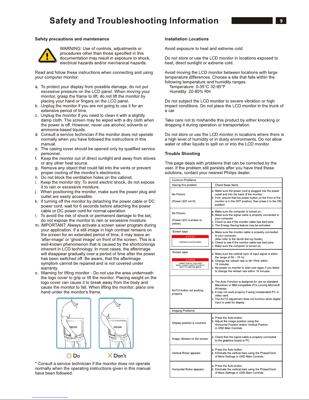
Safety instruction, warnings and notes
index of this chapter:
1 Safety Instructions
2 Warnings
3 Notes
1 Safety Instructions
Safety regulations require that during a repair:
a. Connect the set to the AC Power via an isolation transformer
(> 800 VA).
b. Replace safety components, indicated by the symbol ,
only by components identical to the original ones. Any other
component substitution (other than original type) may
increase risk of fire or electrical shock hazard.
Safety regulations require that after a repair, the set must be
returned in its original condition. Pay in particular attention to
the following points:
a. Route the wire trees correctly and fix them with the mounted
cable clamps.
b. Check the insulation of the AC Power lead for external
damage.
c. Check the strain relief of the AC Power cord for proper
function.
d. Check the electrical DC resistance between the AC Power
plug and the secondary side (only for sets which have a AC
Power isolated power supply):
* Unplug the AC Power cord and connect a wire between the
two pins of the AC Power plug.
* Set the AC Power switch to the "on" position (keep the AC
Power cord unplugged!).
* Measure the resistance value between the pins of the AC
Power plug and the metal shielding of the tuner or the aerial
connection on the set. The reading should be between 4.5
Mohm and 12 Mohm.
* Switch "off" the set, and remove the wire between the two
Pins of the AC Power plug.
e. Check the cabinet for defects, to avoid touching of any inner
parts by the customer.
2 Warnings
a. All ICs and many other semiconductors are susceptible to
electrostatic discharges (ESD ). Careless handling during
repair can reduce life drastically. Make sure that, during
repair,
you are connected with the same potential as the mass of the
set by a wristband with resistance. Keep components and
tools also at this same potential.
b. Be careful during measurements in the high voltage section.
c. Never replace modules or other components while the unit
is switched "on".
d. When you align the set, use plastic rather than metal tools.
This will prevent any short circuits and the danger of a circuit
becoming unstable.
3 Notes
3.1 General
Measure the voltages and waveforms with regard to the
chassis ground or hot ground, depending on the tested area of
circuitry. The voltages and waveforms shown in the diagrams
are indicative.
The semiconductors indicated in the circuit diagram and in the
parts lists, are interchangeable per position with the
semiconductors in the unit, irrespective of the type indication on
3.2 Schematic Notes
All resistor values are in ohms and the value multiplier is often
used to indicate the decimal point location (e.g. 2K2 indicates
2.2 Kohm).
Resistor values with no multiplier may be indicated with either
an "E" or an "R" (e.g. 220E or 220R indicates 220 ohm).
All capacitor values are given in micro-farads ( X10 ),
nano-farads (n= X10 ), or pico-farads (p= X10 ).
Capacitor values may also use the value multiplier as the
decimal point indication (e.g. 2p2 indicates 2.2 pF).
An "asterisk" (*) indicates component usage varies. Refer to the
diversity tables for the correct values.
The correct component values are listed in the Electrical
Replacement Parts List. Therefore, always check this list when
there is any doubt.
3.3 Lead Free Solder
Philips CE is going to produce lead-free sets (PBF) from
1.1.2005 onwards.
Lead-free sets will be indicated by the PHILIPS-lead-free logo
on the Printed Wiring Boards (PWB):
This sign normally has a diameter of 6 mm, but if there is less
space on a board also 3 mm is possible.
In case of doubt wether the board is lead-free or not (or with
mixed technologies), you can use the following method:
* Always use the highest temperature to solder, when using
SAC305 (see also instructions below).
* De-solder thoroughly (clean solder joints to avoid mix of
two alloys).
: For BGA-ICs, you must use the correct temperature
profile, which is coupled to the 12NC. For an overview of these
profiles, visit the website
You will find this and more technical information within the
"Magazine", chapter "Workshop information".
For additional questions please contact your local repair desk.
Due to lead-free technology some rules have to be respected
by the workshop during a repair:
Use only lead-free soldering tin Philips SAC305 with order code
0622 149 00106. If lead-free solder paste is required, please
contact the manufacturer of your soldering equipment.
In general, use of solder paste within workshops should be
avoided because paste is not easy to store and to handle.
Use only adequate solder tools applicable for lead-free
soldering tin. The solder tool must be able
- To reach at least a solder-tip temperature of 400 degree C.
- To stabilise the adjusted temperature at the solder-tip.
- To exchange solder-tips for different applications.
-6
-9 -12
Caution
http://www.atyourservice.ce.philips.com/
200VW8 LCD
Block Diagram
23
S-A3
200BW8 LCD
23
A2
2.POWER
on_BACKLIGHT
Adj_BACKLIGHT
VCC1.8
VCC3.3
+5V
VCC12
VCTRL
PC5V
A4
4.SCALER
DDCD_SDA
CLK-
DDCA_SDA
VSYNC
HSYNC
LVACKP
DDCD_SCL
DET_VGA
on_PANEL
DDCA_SCL
LVA3M
+5V
VCC3.3
VCC1.8
RIN
GNDG
GIN
BIN
GNDB
SOG
GNDR
R+
R-
G-
B+
B-
G+
CLK+
on_BACKLIGHT
Adj_BACKLIGHT
LVA3P
LVA2M
LVACKM
LVA2P
LVA1P
LVA1M
LVA0M
LVA0P
LVBCKP
LVB1P
LVB0P
LVBCKM
LBA2M
LVB3P
LVB0M
LVB2P
LVB1M
LVB3M
HPD_CTRL
DET_DVI
VCTRL
MUTE
VOLUME
STBY
A5
5.PANEL
LVB1M
LVB0M
LVB2P
LVA1 M
LVB2M
LVB3M
LVA3 P
LVBCKP
LVB3P
LVA1P
LVB1P
LVA0 M
LVBCKM
LVA3 M
LVA0 P
LVB0P
LVACKP
LVA2 P
LVACKM
LVA2 M
on_PANEL
+5V
VCC12
A3
3.INPUT
RIN
GIN
BIN
VSYNC
GNDR
GNDG
GNDB
DET_VGA
HSYNC
SOG
DDCA_SDA
DDCA_SCL
B-
G+
G-
R-
CLK-
R+
CLK+
B+
DDCD_SDA
DDCD_SCL
PC5V
DET_DVI
HPD_CTRL
A6
6.AUDIO
VOLUME
STBY
MUTE
VCC12
VCC3.3
+5V
VCC12
+5V VCC1.8
VCC3.3
PC5V
PC5V
VCC12+5V
VCC3.3
VCC1.8
VCC12
VCC3.3
200BW8 LCD
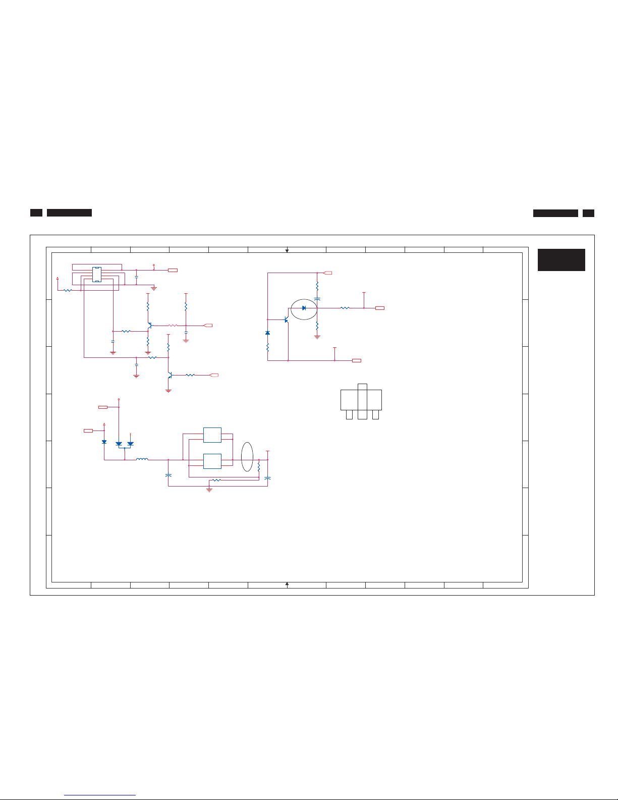
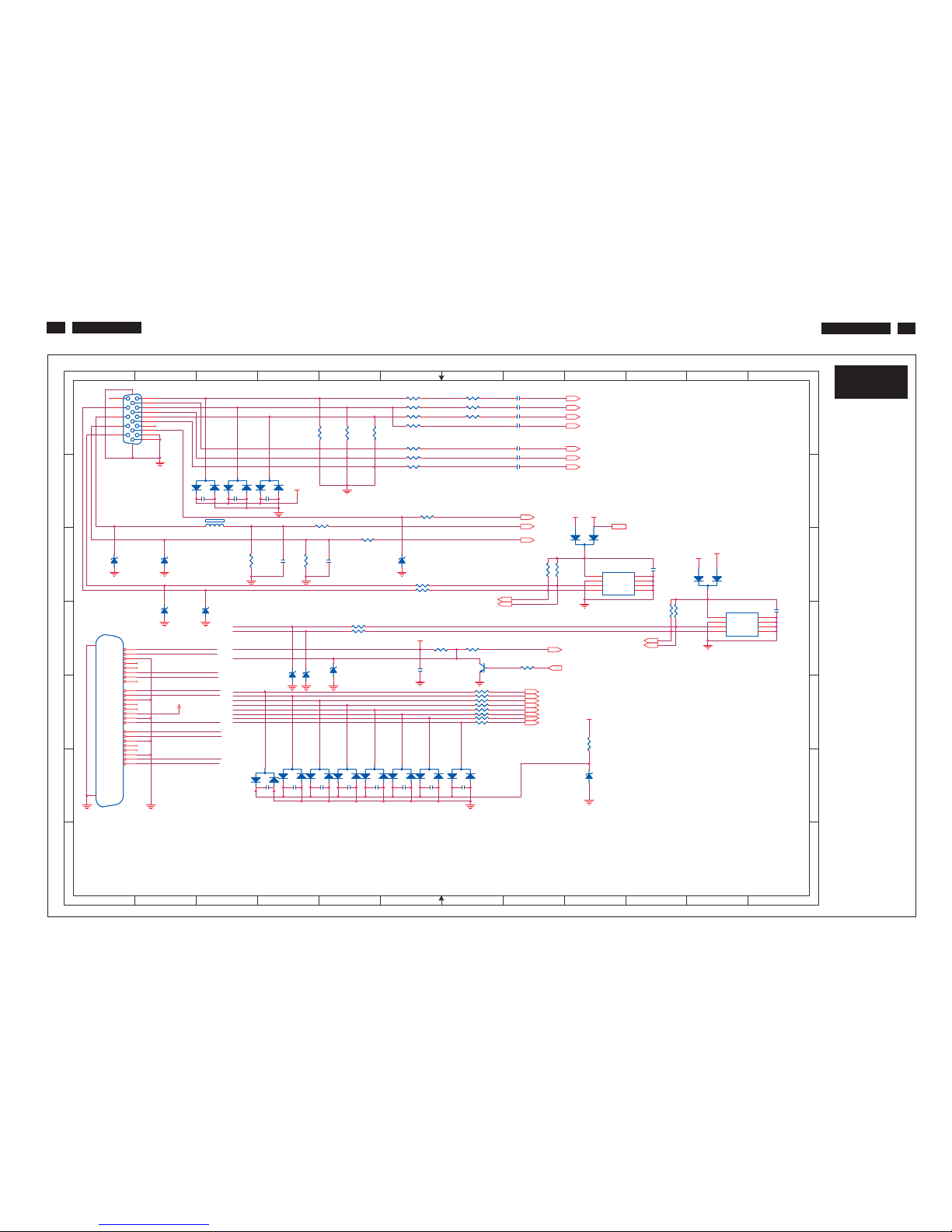
Schematic Diagram(Scaler Board - Power)
24
S-A3
200BW8 LCD
24
S-A2
1
1
2
2
3
3
4
4
5
5
6
6
7
7
8
8
9
9
10
10
11
11
12
12
A A
B
B
C C
D
D
E E
F F
G G
on_BACKLIGHT 4
Adj_BACKLIGHT 4
VCC1.8 4
VCC3.3 4,6
+5V
3,4,5
VCC12 5,6
VCTRL 4
PC5V3
VCC3.3
VCC12
VCC3.3 VCC3.3
VCC3.3
PC5V
VCC3.3
VCC1.8
+5V
+5V
ECB
D1 SOT-89
D2
1N4148D21N4148
R7
47/6R747/6
U1
LT1084/TO263U1LT1084/TO263
ADJ/GND
1
VOUT2VIN
3
OUT
4
C6
1uF/8/NCC61uF/8/NC
L1
CX201209813/8L1CX201209813/8
Q3
2SB1132PTQ32SB1132PT
C
B
E
R2
0/6R20/6
+
C8
330u/16V
+
C8
330u/16V
U3-A1
LT1117/TO252/NC
U3-A1
LT1117/TO252/NC
ADJ/GND
1
VOUT2VIN
3
OUT
4
C3
0.1uF/6/NCC30.1uF/6/NC
CN1 CONN 4x2-RCN1 CONN 4x2-R
4
5 6
1
2
3
8
7
+
C7
330u/16V
+
C7
330u/16V
C1
0.1uF/6C10.1uF/6
R5 10K/6R5 10K/6
R4 1K/6R4 1K/6
R12
2K/6
R12
2K/6
R13
100/6
R13
100/6
Q2
2N3904Q22N3904
31
2
R10 0/6R10 0/6
D4
SSM12LLD4SSM12LL
R11 2.2K/6R11 2.2K/6
R6
10K/6R610K/6
R9 0/6R9 0/6
C4
1uF/8C41uF/8
R17
200/6 1%
R17
200/6 1%
Q1
MMST3906Q1MMST3906
R18
330/6 1%
R18
330/6 1%
+
C5
4.7uF/16V
+
C5
4.7uF/16V
D1
SSM12LLD1SSM12LL
R1
0/1206R10/1206
D3
BAT54C-GS08D3BAT54C-GS08
R8
1K/6R81K/6
R3
10K/6R310K/6
CN1 A2
C1 A3
C3 B4
C4 B2
C5 A7
C6 C3
C7 E 3
C8 E 6
D1 B7
D2 B6
D3 D2
D4 D2
L1 E3
Q1 B3
Q2 C3
Q3 B6
R1 A1
R2 B3
R3 B4
R4 B3
R5 B2
R6 B3
R7 A7
R8 B3
R9 C3
R10 B8
R11 C4
R12 B7
R13 B6
R17 E6
R18 E4
U1 E4
U3-A1 D4
200BW8 LCD
Schematic Diagram(Scaler Board - Input)
25
S-A3
200BW8 LCD
25
S-A3
1
1
2
2
3
3
4
4
5
5
6
6
7
7
8
8
9
9
10
10
11
11
12
12
A A
B
B
C C
D
D
E E
F F
G G
PC5V
VSI
HSI
CLK_DDC
DAT_DDC
DVI_SDA
DAT1-
DAT0DAT1+
ESD_5V
DAT1-
DVI_SCL
DAT2+
DAT0+
HPD
DAT2DAT2+
DAT0+
DAT0-
DVI_SDA
DAT2-
DVI_SCL
DCLK+
DAT1+
HPD
DCLK-
DVI5V
DVI5V
DCLK+
DCLK-
RIN 4
GIN 4
BIN 4
VSYNC 4
GNDR 4
GNDG 4
GNDB 4
DET_VGA 4
HSYNC 4
SOG 4
DDCA_SDA4
DDCA_SCL4
B- 4
G+ 4
G- 4
R- 4
CLK- 4
R+ 4
CLK+ 4
B+ 4
DDCD_SDA4
DDCD_SCL4
PC5V 2
DET_DVI 4
HPD_CTRL 4
ESD_5V
DVI5V
+5V
DVI5V
+5V
+5V PC5V
DVI5V
R
G
B
R39 100/61%R39 100/61%
R59 10/6/NCR59 10/6/NC
D6
BAV99/NCD6BAV99/NC
3
2
1
C29
0.1uF/6/NC
C29
0.1uF/6/NC
C18 47nF/6C18 47nF/6
R46
10K/6/NC
R46
10K/6/NC
R55 100/6/NCR55 100/6/NC
R52 100/6/NCR52 100/6/NC
R60 10/6/NCR60 10/6/NC
Q6
2N3904/NCQ62N3904/NC
31
2
D25
BAV99/NC
D25
BAV99/NC
3
2
1
R27 56/61%R27 56/61%
C15 47nF/6C15 47nF/6
U2
AT24C02N-10SC/NC
U2
AT24C02N-10SC/NC
A0
1
A1
2
A2
3
GND4SDA
5
SCL
6
WP
7
VCC
8
D8
BAT54C-GS08/NC
D8
BAT54C-GS08/NC
3
1
2
C14 47nF/6C14 47nF/6
C23
33pF/6
C23
33pF/6
D18
BAV99/NC
D18
BAV99/NC
3
2
1
C32
0.1uF/6/NC
C32
0.1uF/6/NC
U3
AT24C02N-10SC/NC
U3
AT24C02N-10SC/NC
A0
1
A1
2
A2
3
GND4SDA
5
SCL
6
WP
7
VCC
8
D23
BAV99/NC
D23
BAV99/NC
3
2
1
D26
Z3.6V/NC
D26
Z3.6V/NC
R61 10/6/NCR61 10/6/NC
R43 1K/6R43 1K/6
D22
BAV99/NC
D22
BAV99/NC
3
2
1
R54 10K/6/NCR54 10K/6/NC
C21 0.1uF/6/NCC21 0.1uF/6/NC
R50
10K/6/NC
R50
10K/6/NC
D17
Z5.6V/NC
D17
Z5.6V/NC
D11
Z5.6V/NC
D11
Z5.6V/NC
C26
0.1uF/6/NC
C26
0.1uF/6/NC
R34
75/6 1%
R34
75/6 1%
D20
BAV99/NC
D20
BAV99/NC
3
2
1
R49 100/6R49 100/6
C30
0.1uF/6/NC
C30
0.1uF/6/NC
D14
Z5.6V/NC
D14
Z5.6V/NC
D9
Z5.6V/NCD9Z5.6V/NC
R31 56/61%R31 56/61%
R51
10K/6/NC
R51
10K/6/NC
R64 10/6/NCR64 10/6/NC
C24
33pF/6
C24
33pF/6
D24
BAV99/NC
D24
BAV99/NC
3
2
1
C27
0.1uF/6/NC
C27
0.1uF/6/NC
C35
0.1uF/6/NC
C35
0.1uF/6/NC
R44
2.2K/6
R44
2.2K/6
C20 0.1uF/6/NCC20 0.1uF/6/NC
CN4
DVI-D/NC
CN4
DVI-D/NC
RX2-
1
RX2+
2
GND
3
RX4-
4
RX4+
5
SCL
6
SDA
7
VS
8
RX1-
9
RX1+
10
GND
11
RX3-
12
RX3+
13
5V
14
GND
15
HP
16
RX0-
17
RX0+
18
GND
19
RX5-
20
RX5+
21
GND
22
RXC+
23
RXC-
24
26
25
D12
BAT54C-GS08/NC
D12
BAT54C-GS08/NC
3
1
2
R57 10/6/NCR57 10/6/NC
D7
BAV99/NCD7BAV99/NC
3
2
1
C33
0.1uF/6/NC
C33
0.1uF/6/NC
R28 30/6beadR28 30/6bead
R48 100/6R48 100/6
C16 10n/6C16 10n/6
C19 47nF/6C19 47nF/6
D10
Z5.6V/NC
D10
Z5.6V/NC
D13
Z5.6V/NC
D13
Z5.6V/NC
R42 1K/6R42 1K/6
C28
0.1uF/6/NC
C28
0.1uF/6/NC
R53 100/6/NCR53 100/6/NC
R35
75/6 1%
R35
75/6 1%
R47
10K/6/NC
R47
10K/6/NC
D16
Z5.6V/NC
D16
Z5.6V/NC
R45
2.2K/6
R45
2.2K/6
R37 100/61%R37 100/61%
CN3
VGA
CN3
VGA
1
6
2
7
3
8
4
9
5
11
12
13
14
15
10
1617
R56 4.7K/6/NCR56 4.7K/6/NC
R30 30/6beadR30 30/6bead
R32 30/6beadR32 30/6bead
C22 0.1uF/6/NCC22 0.1uF/6/NC
R41 100/6/NCR41 100/6/NC
C31
0.1uF/6/NC
C31
0.1uF/6/NC
C34
0.1uF/6/NC
C34
0.1uF/6/NC
R29 56/61%R29 56/61%
R38 100/61%R38 100/61%
D15
Z5.6V/NC
D15
Z5.6V/NC
R58 10/6/NCR58 10/6/NC
D19
BAV99/NC
D19
BAV99/NC
3
2
1
C25
0.1uF/6/NC
C25
0.1uF/6/NC
R65 10/6/NCR65 10/6/NC
R33 470/6R33 470/6
D21
BAV99/NC
D21
BAV99/NC
3
2
1
FB1 0/6FB1 0/6
R63
10K/6/NC
R63
10K/6/NC
C13 47nF/6C13 47nF/6
D5
BAV99/NCD5BAV99/NC
3
2
1
R62 10/6/NCR62 10/6/NC
R36
75/6 1%
R36
75/6 1%
C17 47nF/6C17 47nF/6
C13 A8 D26 F9
C14 A8 FB1 B3
C15 A8 Q6 D7
C16 A8 R27 A6
C16 D8 R28 A7
C17 A8 R29 A6
C18 A8 R30 A7
C19 B8 R31 A6
C20 B3 R32 A7
C21 B3 R33 A6
C22 B4 R34 A4
C23 C4 R35 A5
C24 C4 R36 A5
C25 C10 R37 A6
C26 C12 R38 A6
C27 D6 R39 B6
C28 F4 R41 B6
C29 F4 R42 B4
C30 F4 R43 B5
C31 F5 R43 C5
C32 F5 R44 C3
C33 F6 R45 C4
C34 F6 R46 C8
C35 F7 R47 C8
CN3 A1 R48 C6
CN4 D1 R49 C6
D5 B2 R50 C1 0
D6 B3 R51 C1 0
D7 B3 R52 B 5
D8 B8 R52 D5
D9 C1 R53 B5
D10 C2 R53 D5
D11 C6 R54 D6
D12 C10 R55 D7
D13 C2 R56 D8
D14 C3 R57 E7
D15 D5 R58 E7
D16 D4 R59 E7
D17 D4 R60 E7
D18 F3 R61 E7
D19 F4 R62 E7
D20 F4 R63 E9
D21 F5 R64 E7
D22 F5 R65 E7
D23 F6 U2 C9
D24 F6 U3 D11
D25 F6
 Loading...