

Page 1
Page 2

IMPORTANT SAFETY NOTICE
Proper service and repair is important to the safe, reliable operation of all Philips
Consumer Electronics Company** Equipment. The service procedures recommended by
Philips and described in this service manual are effective methods of performing service
operations. Some of these service operations require the use of tools specially designed
for the purpose. The special tools should be used when and as recommended.
It is important to note that this manual contains various CAUTIONS and NOTICES
which should be carefully read in order to minimize the risk of personal injury to service
personnel. The possibility exists that improper service methods may damage the
equipment. It also is important to understand that these CAUTIONS and NOTICES
ARE NOT EXHAUSTIVE. Philips could not possibly know, evaluate and advise the
service trade of all conceivable ways in which service might be done, or of the possible
hazardous consequences of each way. Consequently, Philips has not undertaken any such
broad evaluation. Accordingly, a servicer who uses a service procedure or tool which is
not recommended by Philips must first satisfy himself thoroughly that neither his safety
nor the safe operation of the equipment will be jeopardized by the service method
selected.
** Hereafter throughout this manual, Philips Consumer Electronics Company will be
referred to as Philips.
WARNING
Critical components having special safety characteristics are identified with a or
"S" by the Ref. No. in the parts list and enclosed within a broken line* (where
several critical components are grouped in one area) along with the safety symbol
on the schematics or exploded views. Use of substitute replacement parts which
do not have the same specified safety characteristics may create shock, fire, or other
hazards. Under no circumstances should the original design be modified or altered
without written permission from Philips. Philips assumes no liability, express or
implied, arising out of any unauthorized modification of design. Servicer assumes all
liability.
* Broken Line ____ _ ____ _ ____ _ ____
Page 3

FIRE AND SHOCK HAZARD
1. Be sure all components are positioned in such a way as to avoid the possibility of adjacent component
shorts. This is especially important on those chassis which are transported to and from the service shop.
2. Never release a repaired unit unless all protective devices such as insulators, barriers, covers, strain
reliefs, and other hardware have been installed in accordance with the original design.
3. Soldering and wiring must be inspected to locate possible cold solder joints, solder splashes, sharp solder
points, frayed leads, pinched leads, or damaged insulation (including the ac cord). Be certain to remove
loose solder balls and all other loose foreign particles.
4. Check across-the-line components and other components for physical evidence of damage or
deterioration and replace if necessary. Follow original layout, lead length, and dress.
5. No lead or component should touch a receiving tube or a resistor rated at 1 watt or more. Lead tension
around protruding metal surfaces or edges must be avoided.
6. Critical components having special safety characteristics are identified with an 'S' by the Ref. No. in the
parts list and enclosed within a broken line* (where several critical components are grouped in one area)
along with the safety symbol on the schematic diagrams and /or exploded views.
7. When servicing any unit, always use a separate isolation transformer for the chassis. Failure to use a
separate isolation transformer may expose you to possible shock hazard, and may cause damage to
servicing instruments.
8. Many electronic products use a polarized ac line cord (one wide pin on the plug). Defeating this safety
feature may create a potential hazard to the servicer and the user. Extension cords which do not
incorporate the polarizing feature should never be used.
9. After reassembly of the unit, always perform an ac leakage test or resistance test from the line cord to all
exposed metal parts of the cabinet. Also, check all metal control shafts (with knobs removed), antenna
terminals, handles, screws, etc., to be sure the unit may be safely operated without danger of electrical
shock.
* Broken line ____ _ ____ _ ____ _ ____
Page 4

LEAKAGE CURRENT COLD CHECK
1. Unplug the ac line cord and connect a jumper between the two prongs of the plug.
2. Turn on the power switch.
3. Measure the resistance value between the jumpered ac plug and all exposed cabinet parts of the receiver,
such as screw heads, antennas, and control shafts. When the exposed metallic part has a return path to the
chassis, the reading should be between 1 megohm and 5.2 megohms. When the exposed metal does not
have a return path to the chassis, the reading must be infinity. Remove the jumper from the ac line cord.
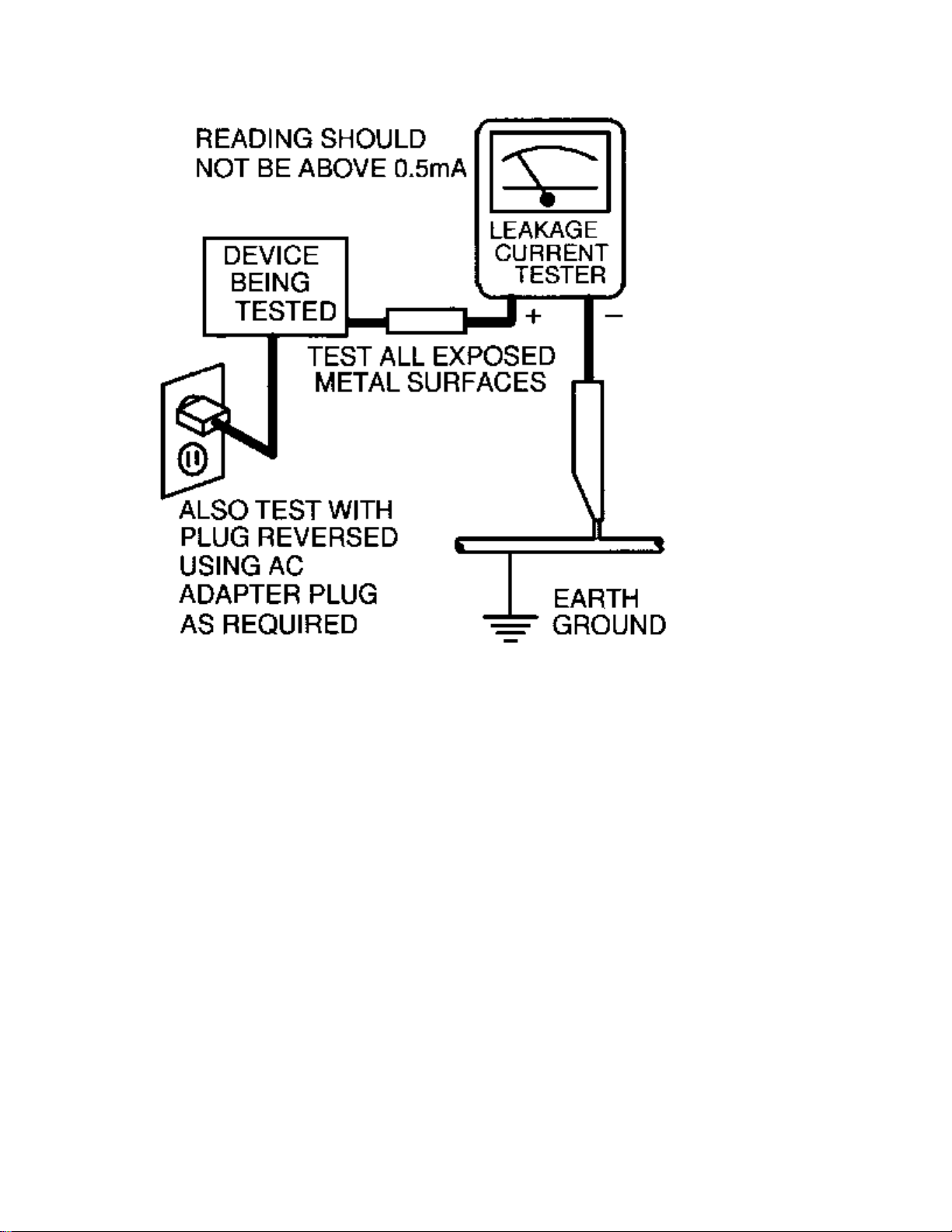
LEAKAGE CURRENT HOT CHECK
1. Do not use an isolation transformer for this test. Plug the completely reassembled receiver directly into
the ac outlet.
2. Connect a 1.5k, 10W resistor paralleled by a 0.15uF. capacitor between each exposed metallic cabinet
part and a good earth ground such as a water pipe, as shown below.
3. Use an ac voltmeter with at least 5000 ohms/volt sensitivity to measure the potential across the resistor.
4. The potential at any point should not exceed 0.75 volts. A leakage current tester may be used to make
this test; leakage current must not exceed 0.5mA. If a measurement is outside of the specified limits,
there is a possibility of shock hazard. The receiver should be repaired and rechecked before returning it
to the customer.
5. Repeat the above procedure with the ac plug reversed. (Note: An ac adapter is necessary when a
polarized plug is used. Do not defeat the polarizing feature of the plug.)
OR
With the instrument completely reassembled, plug the ac line cord directly into a 120Vac outlet. (Do not
use an isolation transformer during this test.) Use a leakage current tester or a metering system that
complies with American National Standards Institute (ANSI) C101.1 Leakage Current for Appliances and
Underwriters Laboratories (UL) 1410, (50.7). With the instrument ac switch first in the on position and
then in the off position, measure from a known earth ground (metal water pipe, conduit, etc.) to all exposed
metal parts of the instrument (antennas, handle brackets, metal cabinet, screw heads, metallic overlays,
control shafts, etc.), especially any exposed metal parts that offer an electrical return path to the chassis.
Any current measured must not exceed 0.5mA. Reverse the instrument power cord plug in the outlet and
repeat the test. See the graphic below.
Page 5
Page 6

TV SAFETY NOTES
SAFETY CHECKS
After the original service problem has been corrected, a complete safety check should be made. Be sure to
check over the entire set, not just the areas where you have worked. Some previous servicer may have left
an unsafe condition, which could be unknowingly passed on to your customer. Be sure to check all of the
following:
Fire and Shock Hazard
Implosion
X-Radiation
Leakage Current Cold Check
Leakage Current Hot Check
Picture Tube Replacement
Parts Replacement
WARNING: Before removing the CRT anode cap, turn the unit OFF and short the HIGH VOLTAGE to
the CRT DAG ground.
SERVICE NOTE: The CRT DAG is not at chassis ground.
IMPLOSION
1. All picture tubes used in current model receivers are equipped with an integral implosion system.
Care should always be used, and safety glasses worn, whenever handling any picture tube. Avoid
scratching or otherwise damaging the picture tube during installation.
2. Use only replacement tubes specified by the manufacturer.
X-RADIATION
1. Be sure procedures and instructions to all your service personnel cover the subject of X-radiation.
Potential sources of X-rays in TV receivers are the picture tube and the high voltage circuits. The
basic precaution which must be exercised is to keep the high voltage at the factory recommended
level.
2. To avoid possible exposure to X-radiation and electrical shock, only the manufacturer's specified
anode connectors must be used.
3. It is essential that the service technician has an accurate HV meter available at all times. The
calibration of this meter should be checked periodically against a reference standard.
4. When the HV circuitry is operating properly there is no possibility of an X-radiation problem. High
voltage should always be kept at the manufacturer's rated value - no higher - for optimum
performance. Every time a color set is serviced, the brightness should be run up and down while
monitoring the HV with a meter to be certain that the HV is regulated correctly and does not exceed
the specified value. We suggest that you and your technicians review test procedures so that HV and
HV regulation are always checked as a standard servicing procedure, and the reason for this prudent
routine is clearly understood by everyone. It is important to use an accurate and reliable HV meter. It
is recommended that the HV reading be recorded on each customer's invoice, which will
demonstrate a proper concern for the customer's safety.
Page 7

5. When troubleshooting and making test measurements in a receiver with a problem of excessive high
voltage, reduce the line voltage by means of a Variac to bring the HV into acceptable limits while
troubleshooting. Do not operate the chassis longer than necessary to locate the cause of the excessive
HV.
6. New picture tubes are specifically designed to withstand higher operating voltages without creating
undesirable X-radiation. It is strongly recommended that any shop test fixture which is to be used
with the new higher voltage chassis be equipped with one of the new type tubes designed for this
service. Addition of a permanently connected HV meter to the shop test fixture is advisable. The
CRT types used in these new sets should never be replaced with any other types, as this may result in
excessive X-radiation.
7. It is essential to use the specified picture tube to avoid a possible X-radiation problem.
8. Most TV receivers contain some type of emergency "Hold Down" circuit to prevent HV from rising
to excessive levels in the presence of a failure mode. These various circuits should be understood by
all technicians servicing them, especially since many hold down circuits are inoperative as long as
the receiver performs normally.
PICTURE TUBE REPLACEMENT
The primary source of X-radiation in this television receiver is the picture tube. The picture tube
utilized in this chassis is specially constructed to limit X-radiation emissions. For continued Xradiation protection, the replacement tube must be the same type as the original, including suffix letter,
or a Philips approved type.
PARTS REPLACEMENT
Many electrical and mechanical parts in Philips television sets have special safety related
characteristics. These characteristics are often not evident from visual inspection nor can the protection
afforded by them necessarily be obtained by using replacement components rated for higher voltage,
wattage, etc. The use of a substitute part which does not have the same safety characteristics as the
Philips recommended replacement part shown in this service manual may create shock, fire, or other
hazards.
PRODUCT SAFETY GUIDELINES FOR ALL PRODUCTS
CAUTION: Do not modify any circuit. Service work should be performed only after you are thoroughly
familiar with all of the following safety checks. Risk of potential hazards and injury to the user increases if
safety checks are not adhered to.
USE A SEPARATE ISOLATION TRANSFORMER FOR THIS UNIT WHEN SERVICING.
Page 8

PREVENTION OF ELECTROSTATIC DISCHARGE (ESD)
Some semiconductor solid state devices can be damaged easily by static electricity. Such components
commonly are called Electrostatically Sensitive (ES) Devices, Examples of typical ES devices are
integrated circuits and some field-effect transistors and semiconductor "chip" components. The following
techniques should be used to help reduce the incidence of component damage caused by electrostatic
discharge (ESD).
1. Immediately before handling any semiconductor component or semiconductor-equipped assembly, drain
off any ESD on your body by touching a known earth ground. Alternatively, obtain and wear a
commercially available discharging ESD wrist strap, which should be removed for potential shock
reasons prior to applying power to the unit under test.
2. After removing an electrical assembly equipped with ES devices, place the assembly on a conductive
surface such as aluminum foil, to prevent electrostatic charge buildup or exposure of the assembly.
3. Use only a grounded-tip soldering iron to solder or unsolder ES devices.
4. Use only an anti-static solder removal device. Some solder removal devices not classified as "antistatic
(ESD protected)" can generate an electrical charge sufficient to damage ES devices.
5. Do not use Freon propelled chemicals. These can generate electrical charges sufficient to damage ES
devices.
6. Do not remove a replacement ES device from its protective package until immediately before you are
ready to install it (most replacement ES devices are packaged with leads electrically shorted together by
conductive foam, aluminum foil or comparable conductive material).
7. Immediately before removing the protective material from the leads of a replacement ES device, touch
the protective material to the chassis or circuit assembly into which the device will be installed.
CAUTION: Be sure no power is applied to the chassis or circuit and observe all other safety precautions.
8. Minimize bodily motions when handling unpackaged replacement ES devices. (Otherwise harmless
motion such as the brushing together of your clothes fabric or the lifting of your feet from a carpeted
floor can generate static electricity (ESD) sufficient to damage an ES device.)
NOTE to CATV system Installer:
This reminder is provided to call the CATV system installer's attention to article 820-22 of the NEC that
provides guidelines for proper grounding and, in particular, specifies that the cable ground shall be
connected to the grounding system of the building, as close to the point of cable entry as practical.
Page 9

PRACTICAL SERVICE PRECAUTIONS
IT MAKES SENSE TO AVOID EXPOSURE TO ELECTRICAL SHOCK. While some sources are
expected to have a possible dangerous impact, others of quite high potential are of limited current and are
sometimes held in less regard.
ALWAYS RESPECT VOLTAGES. While some may not be dangerous in themselves, they can cause
unexpected reactions – reactions that are best avoided. Before reaching into the powered color TV set, it is
best to test the high voltage insulation. It is easy to do, and is just a good service precaution.
BEFORE POWERING UP THE TV WITH THE BACK OFF (or on a test fixture), attach a clip lead to
the CRT DAG ground and to a screwdriver blade that has a well insulated handle. After the TV is powered
on and high voltage has developed, probe the anode lead with the blade, starting at the bottom of the High
Voltage Transformer (flyback – IFT). Move the blade to within two inches of the connector of the CRT. IF
THERE IS AN ARC, YOU FOUND IT THE EASY WAY, WITHOUT GETTING A SHOCK! If
there is an arc to the screwdriver blade, replace the High Voltage Transformer or the lead, (if removable)
whichever is causing the problem.
PICTURE TUBE REPLACEMENT PROCEDURE
Note: a. Two (2) people are required to handle this picture tube.
b. Safety Glasses must be worn during this procedure or whenever directly handling a picture tube.
c. Take care in each step not to damage the CRT or the cabinet.
1. Remove the Chassis and the CRT Socket Board Module from the cabinet.
2. A furniture pad or blanket should be positioned on the floor to support only the CRT Face. This pad or
blanket should be high enough to keep the CRT Face approximately 12 to 14 inches off the floor.
3. Using two people, place the cabinet in a front down position with the CRT Face on the pad or blanket.
4. Place padded blocks under each corner of the cabinet to keep it from rocking.
5. Remove the four screws, at the corners of the CRT.
6. With two people lowering the cabinet to the floor, leave the CRT elevated by the pad or blanket.
Note: Take care not to grasp the neck of the CRT during this procedure, as it is extremely fragile.
7. Two (2) people may then lift the CRT from the cabinet.
8. Remove the degaussing coil from the defective CRT and mount on the replacement. Take care to
maintain the exact shape and fit.
To install the new CRT, reverse steps 1 to 7.
Page 10

E8 CHASSIS INTRODUCTION
The E8 series chassis is the Small Screen TV chassis produced by Philips Consumer Electronics Company
for the 1999-2000 model year. The E8 is used with 13, 19, and 20 inch CRT’s. The E8 Tuning System
features a 181 channel Tuning System with On-Screen Display. The Tuning System uses two IC’s mounted
on the main chassis. It consists of a Microcomputer IC and Memory IC. The Microcomputer communicates
with the Memory IC, the Customer Keyboard, the Remote Receiver, the U/V Tuner, the TV Signal Processor,
the Stereo Decoder (optional), and the Power On-Off circuitry. The Memory IC retains the settings for
favorite stations, customer control settings, feature settings, and factory setup data.
The chassis features a Very Large Scale Integration (VLSI) IC for TV Signal Processing. This IC performs
Video IF, Sound IF, AFT/AGC control, Horizontal Signal Processing, Vertical Signal Processing,
Horizontal/Vertical Synchronization, Chroma/Luminance Processing, and Video Switching between internal
and external inputs. On-Screen Graphics from the Microcomputer are placed on the main signal within the
TV Signal Processor. Automatic Volume Level (AVL) from the Microcomputer is sent to the TV Signal
Processor (Mono Sets) and to the Stereo Module (DBX Stereo Sets via the I2C bus). AVL for Normal Stereo
is switched by Pin 9 of the Microcomputer, 7600. The Mono version has a 1 watt audio amplifier. The
Normal Stereo version has a 2x1 watt amplifier. The DBX Stereo version has a 2x3 watt amplifier. Latin
American versions of this chassis may have a 2 or 3 watt Mono amplifier.
The E8 chassis features a Switching Mode Power Supply. A ”HOT“ ground reference is used in the primary
side of the power supply. ”COLD“ (signal) ground is used from the secondary of the power supply and
throughout the rest of the chassis. AN ISOLATION TRANSFORMER IS REQUIRED WHEN DOING
SERVICE ON ANY CHASSIS.
CHASSIS SPECIFICATIONS
Channel Tuning:
Antenna: Channels 2 through 69
Cable: Channels 1 through 125
Allowable cable offset ± 2.0 MHz
Operating and Storage Temperatures:
Operating Temperature: +5ºC to +45ºC
Storage Temperature: -25ºC to +70ºC
Audio In/Out:
½ VRMS
System:
NTSC-M only
IF Frequencies:
45.75 Mhz picture, 41.25 MHz sound (intercarrier),
4.5 MHz sound IF
Page 11

Sound Performance:
At 360 mv RMS/1 kHz to Audio input;
Output 1 Watt per channel or 3 Watts per channel with <10% Total Harmonic Distortion (THD).
At 1 Watt RMS, both channels driven, response is within ± 2dB from 20Hz to 20kHz.
Power Supply Voltages:
NAME VALUE TOLERANCE AT COMPONENT
V+3.3 3.3 volts +/- 0.3 volt 2604
V+5vD 5 volts +/- 0.8 volt Emitter of 7612
V+5v 5 volts +/- 0.5 volt Pin 6 of 1000
Vstby 5 volts +/- 0.5 volt 3615
V+7.5v 7.5 volts +/- 0.5 volt 2414
V+8.5v 8.7 volts +/- 0.8 volt 2415
VmainAux 9 volts +/- 1 volt 2561
Vsound 10.5 volts +/- 1 volt 2955 (2X1 W stereo, 1 W mono)
Vsound 16.5 volts +/- 1 volt 2955 (2X3 W stereo)
V+13v 13.5 volts +/- 1 volt 2410 (13“ and 19“ models)
V+13v 13.8 volts +/- 1 volt 2410 (20“ models)
V-13v -13.5 volts +/- 1 volt 2410 (13“ and 19“ models)
V-13v -13.8 volts +/- 1 volt 2410 (20“ models)
MainSupply 95 volts +/- 1.5 volts Pin 2 of 5445
V+190v 190 volts +/- 10 volts 2413
190V 190 volts +/- 10 volts Pin 3 of connector 0244
Mains (AC Power):
60 Hz, 120 volts AC nominal:
Allowed 90 to 132 volts AC
For Auto-Multi-Voltage Only:
60 Hz, 90 to 276 volts AC
Power consumption, worst control setting:
13“ models – 48 Watts
19“ models – 63 Watts
20“ models – 70 Watts
Standby power consumption:
3 Watts +/-10%
High Voltage (EHT):
(At minimum brightness)
Screen Size: 13" 19" 20“
Voltage: 24.1kV +/- 1kV 25.4kV +/- 1kV 27.2kV +/- 1.5kV (for reference only)
Color Temperature:
NORMAL WARM COOL
9200 +/- 10% 8200 +/- 15% 10,200 +/- 15%
Note: Nominal specifications represent the design specifications. All units should be able to approximate
these. Some will exceed and some may drop slightly below these specifications. Limit specifications
represent the absolute worst condition that still might be considered acceptable. In no case should a unit fail
to meet limit specifications.
Page 12

MODEL TO MODULE LIST
The Model to Module list shown below identifies all electrical panels, modules and assemblies used in each
model produced with the E8 chassis. This information was current at time of printing.
Information concerning cabinet parts and cabinet mounted parts (CRT/Yoke/etc.) is shown in the Cabinet
Replacement Parts List.
Replacement part numbers for each module are provided in the Chassis Panel Replacement Parts List.
If you are attempting to service a model equipped with the E8 chassis, the necessary electrical information
should be covered in this service manual, even if the corresponding model number is not listed.
Model Size
Panel Number Description
PHILIPS – MAGNAVOX MODELS
13PT30L1 13“
00A10800 Combi Board
00EME810 Main Chassis
00ASD054 BTSC (Non-DBX) Panel Replacement Parts List
Note: A10800 Combi Board contains the following boards:
Side Interface Panel, Top Customer Control Panel, LED Right Panel and LED Left Panel
13PR19C1 13“
00EME801 Main Chassis
PR1305C1 13“
00EME800 Main Chassis
PR1319C1 13“
00EME803 Main Chassis
PR1390C1 13“
00EME802 Main Chassis
PR1391X1 13“
00EME802 Main Chassis
XR1305C1 13“
00EME800 Main Chassis
XR1391C1 13“
00EME802 Main Chassis
Page 13

19PR19C121 19“
00EME873 Main Chassis
19PR19C122 19“
00EME842 Main Chassis
19PR19C125 19“
00EME832 Main Chassis
19PS56C121 19“
00EME876 Main Chassis
00ASD050 2X1Watt Stereo Module
19PS56C122 19“
00EME847 Main Chassis
00ASD050 2X1Watt Stereo Module
19PS56C125 19“
00EME837 Main Chassis
00ASD050 2X1Watt Stereo Module
19PT10C125 19“
00EME839 Main Chassis
PR1903C121 19“
00EME870 Main Chassis
PR1903C122 19“
00EME840 Main Chassis
PR1903C125 19“
00EME830 Main Chassis
PR1920C121 19“
00EME874 Main Chassis
PR1920C122 19“
00EME846 Main Chassis
PR1920C125 19“
00EME836 Main Chassis
PS1946C121 19“
00EME875 Main Chassis
00ASD050 2X1Watt Stereo Module
PS1946C122 19“
00EME843 Main Chassis
00ASD050 2X1Watt Stereo Module
Page 14

PS1946C125 19“
00EME833 Main Chassis
00ASD050 2X1Watt Stereo Module
PS1956C121 19“
00EME872 Main Chassis
00ASD050 2X1Watt Stereo Module
PS1956C122 19“
00EME844 Main Chassis
00ASD050 2X1Watt Stereo Module
PS1956C125 19“
00EME834 Main Chassis
00ASD050 2X1Watt Stereo Module
PS1966C121 19“
00EME871 Main Chassis
00ASD052 DBX 2X1Watt Stereo Module
PS1966C122 19“
00EME845 Main Chassis
00ASD052 DBX 2X1Watt Stereo Module
PS1966C125 19“
00EME835 Main Chassis
00ASD052 DBX 2X1Watt Stereo Module
XR1903C121 19“
00EME870 Main Chassis
XR1903C122 19“
00EME840 Main Chassis
XR1903C125 19“
00EME830 Main Chassis
XS1956C121 19“
00EME872 Main Chassis
00ASD050 2X1Watt Stereo Module
XS1956C122 19“
00EME844 Main Chassis
00ASD050 2X1Watt Stereo Module
XS1956C125 19“
00EME834 Main Chassis
00ASD050 2X1Watt Stereo Module
Page 15

PHILIPS
20PT30B122 20“
00AVJ240 Side AV Jack Panel
00EME838 Main Chassis
00ASD051 DBX 2X3Watt Stereo Module
PHILIPS - LATIN AMERICA 110V
14LL190121 13“
00EME824 Main Chassis
14LW192221 13“
00EME822 Main Chassis
00ASD049 DBX 2X3Watt Stereo Module
14LX1903 13“
00EME820 Main Chassis
20LL290125 19“
00EME850 Main Chassis
20LL291125 19“
00EME851 Main Chassis
20LW292225 19“
00EME852 Main Chassis
00ASD049 DBX 2X3Watt Stereo Module
20LW293225 19“
00EME853 Main Chassis
00ASD049 DBX 2X3Watt Stereo Module
20LX2903 19“
00EME854 Main Chassis
21LW392221 20“
00AVJ240 Side AV Jack Panel
00EME860 Main Chassis
00ASD051 DBX 2X3Watt Stereo Module
Page 16

PHILIPS - INDUSTRIAL TELEVISION SMARTPORT
HC9913C1 13“
00EME893 Main chassis
00A10809 Healthcare Jack Panel
HC9919C1 19“
00EME892 Main Chassis
00A10779 Healthcare Jack Panel
PL9119C125 19“
00EME890 Main Chassis
TL9119C125 19“
00EME890 Main Chassis
PHILIPS ITV CARD SETS
PC9219C1 19“
00A10777 Interface Module
00EME891 Main Chassis
PC9219PKIT 19“
00A10777 Interface Module
00EME891 Main Chassis
00PROKIT Pro Video Card Kit
00A10758 Pro Video Card
00A10759 Pro Video Jack Panel
SEC919C1 19“
00EME891 Main Chassis
PA9019C1 19“
00A10777 Interface Module
00A10811 L9 Event Timer
00AVJ250 Provideo Card Assembly
00A10758 Pro Video Card
00A10759 Pro Video Jack Panel
00EME895 Main Chassis
00ASD052 DBX 2X1Watt Stereo Module
CH1919C1 19“
00A10680 Channel One Card
00A10777 Interface Module
00EME891 Main Chassis
Page 17

MODEL TO REMOTE CROSS-REFERENCE
MODEL CHASSIS REMOTE REM. DESCR.
PR1305 C1, XR1305 C1 EME800 RC0702/04 21PB LOW
13PR19 C1 EME801 RCL9UB/04 29PB BBY WST
PR1390 C1, PR1391 X1, XR1391 C1 EME802 RCL9UBW/04 29PB BBY WST
PR1319 C1 EME803 RCL9UB/04 29PB BBY WST
14LX19 03 EME820 RC0737/01 24 PB STEP
14LL19 1121 EME821 RC0737/01 24 PB STEP
14LW19 2221 EME822 RCL9UB/01 29PB BBY WST
14LW19 3221 EME823 RCL9UB/01 29PB BBY WST
14LL19 0121 EME824 RC0737/01 24 PB STEP
PR1903 C125, XR1903 C125 EME830 RC0702/04 21 PB LOW
19PR19 C125 EME832 RCL9UB/04 29PB BBY WST
PS1946 C125 EME833 RC0702/04 21 PB LOW
XS1956 C125 EME834 RCL9UB/04 29PB BBY WST
PS1966 C125 EME835 RCU82C UNI WST-1
PR1920 C125 EME836 RCL9UB/04 29PB BBY WST
19PS56 C125 EME837 RCL9UB/04 29PB BBY WST
20PT30 B1 EME838 RCU82CP UNI WST-1
PR1903 C122, XR1903 C122 EME840 RC0702/04 21 PB LOW
19PR19 C122 EME842 RCL9UB/04 29PB BBY WST
PS1946 C122 EME843 RC0702/04 21 PB LOW
PS1956 C122, XS1956 C122 EME844 RCL9UB/04 29PB BBY WST
PS1966 C122 EME845 RCU82C UNI WST-1
PR1920 C122 EME846 RCL9UB/04 29PB BBY WST
19PS56 C122 EME847 RCL9UB/04 29PB BBY WST
20LL29 0125 EME850 RC0737/01 24 PB STEP
20LL29 1125 EME851 RC0737/01 24 PB STEP
20LW29 2225 EME852 RCL9UB/01 29PB BBY WST
20LW29 3225 EME853 RCL9UB/01 29PB BBY WST
20LX29 0325 EME854 RC0737/01 24 PB STEP
20LX29 0322 EME855 RC0737/01 24 PB STEP
20LL29 0122 EME856 RC0737/01 24 PB STEP
20LW29 2222 EME857 RCL9UB/01 29PB BBY WST
21LW39 2221 EME860 RCL9UB/01 29PB BBY WST
21LW39 3221 EME861 RCL9UB/01 29PB BBY WST
PL9119 C1, TL9119 C1 EME890 RC0705/00 20PB
PC9219 C1 EME891 T374AH-PH02 * 21PB *
* Some Models Only
Page 18
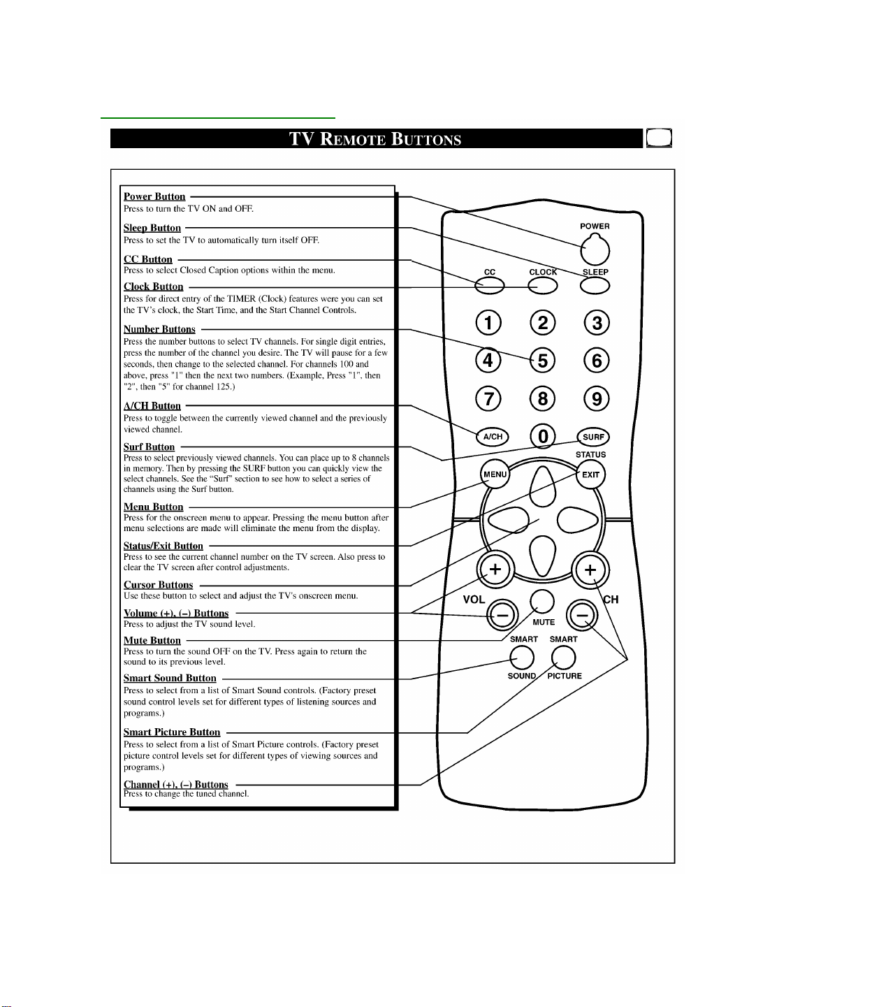
Quick-Use Guide for RC0702
Page 19
Quick-Use Guide for RCU82C
Page 20
Quick-Use Guide for RCL9UB
Page 21
Model to Chassis to Jack Panel
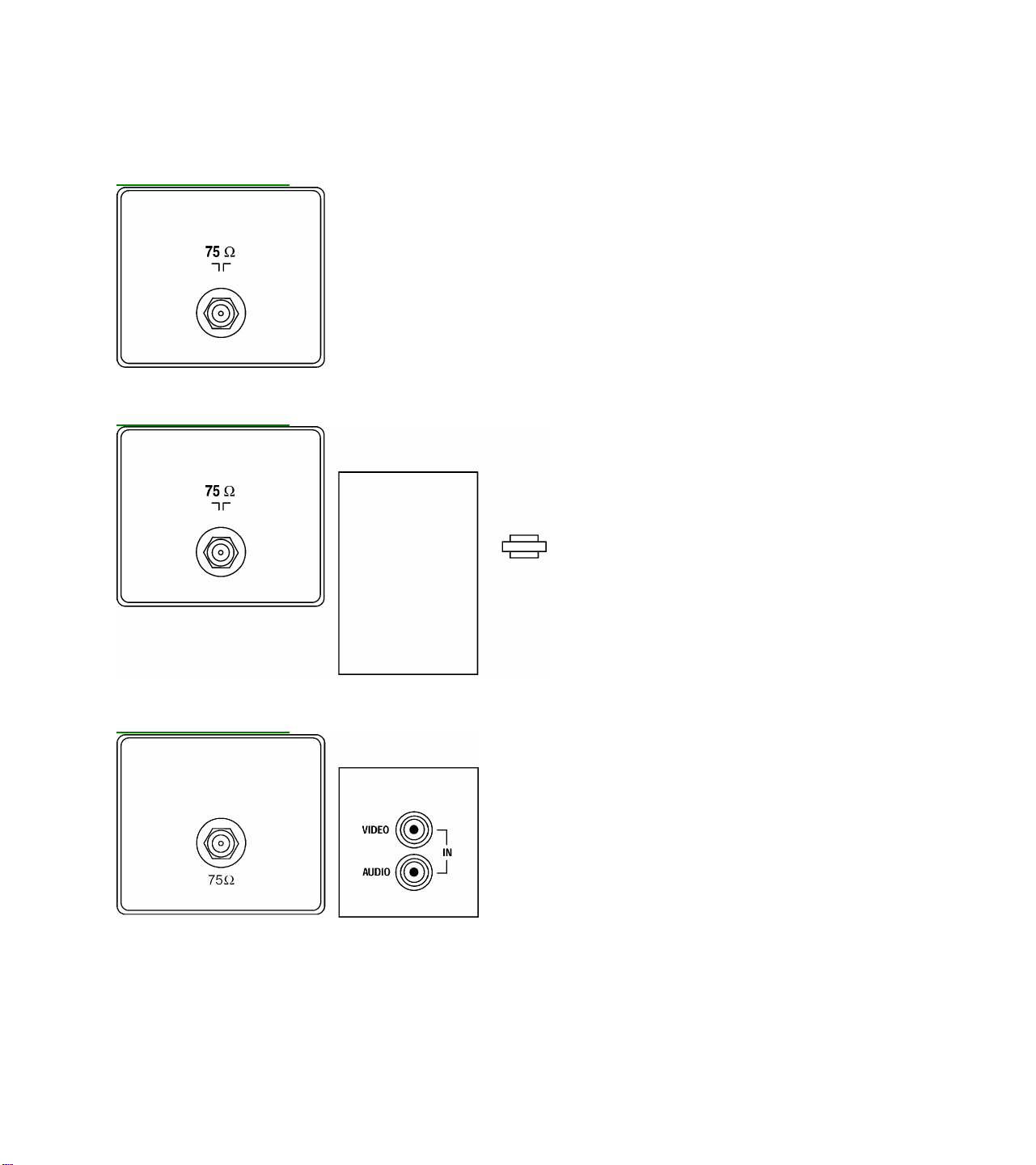
JP9000 Jack Panel
JP9202 Jack Panel
JP9403 Jack Panel
Page 22
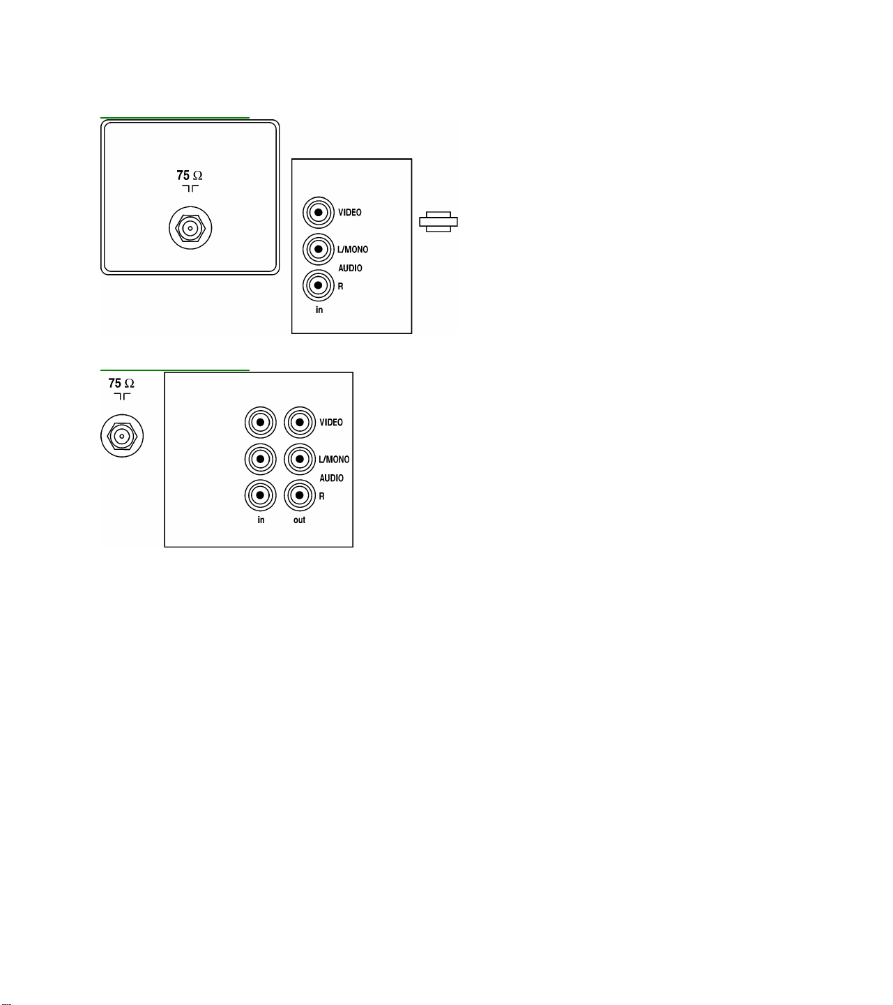
JP9406 Jack Panel
JP9410 Jack Panel
Page 23

MODEL CHASSIS JACK
PANEL
PR1305C121 XR1305C121 EME800 JP9000
13PR19C121 EME801 JP9202
PR1390C121 PR1391X121 XR1391C121 EME802 JP9403
PR1319C121 EME803 JP9202
13PT30L121 EME810 JP9504
14LX190321 EME820 JP9403
14LW192221 EME822 JP9410
14LL190121 EME824 JP9403
PR1903C125 XR1903C125 EME830 JP9000
19PR19C125 EME832 JP9202
PS1946C125 EME833 JP9000
PS1956C125 XS1956C125 EME834 JP9406
PS1966C125 EME835 JP9410
PR1920C125 EME836 JP9202
19PS56C125 EME837 JP9406
19PT10C125 EME839 JP9202
PR1903C122 XR1903C122 EME840 JP9000
19PR19C122 EME842 JP9202
PS1946C122 EME843 JP9000
PS1956C122 XS1956C122 EME844 JP9406
PS1966C122 EME845 JP9410
PR1920C122 EME846 JP9202
19PS56C122 EME847 JP9406
20LL290125 EME850 JP9403
20LL291125 EME851 JP9403
20LW292225 EME852 JP9410
20LW293225 EME853 JP9410
20LX290325 EME854 JP9403
EME855 JP9403
21LW392221 EME860 JP9610
EME861 JP9610
PR1903C121 XR1903C121 EME870 JP9000
PS1966C121 EME871 JP9410
PS1956C121 XS1956C121 EME872 JP9202
19PR19C121 EME873 JP9202
PR1920C121 EME874 JP9202
PS1946C121 EME875 JP9000
Page 24
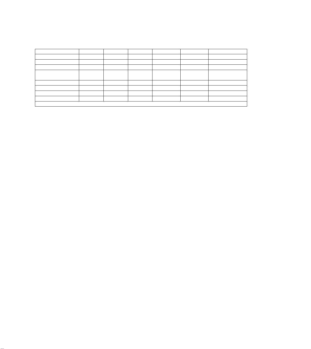
JACK PANEL DEFINITIONS
JP9000 JP9202 JP9403 JP9406 JP9410 JP9610
RF INPUT/ANTENNA 75 OHM 75 OHM 75 OHM 75 OHM 75 OHM 75 OHM
JACKS QUANTITY 0 2 3 7 10 10
VIDEO INPUT 1 1 1 2 2
AUDIO INPUT 1 1 L-R 2 (L-R) 2 (L-R)
(1 Rear, 1 Side)
HEADPHONE FRONT FRONT FRONT
VIDEO OUTPUT 1 1 1
AUDIO OUTPUT L-R (FIXED) L-R (FIXED) L-R (FIXED)
* Only one set of audio output jacks, menu selectable, switchable between fixed and variable output.
GLOSSARY OF TERMS, ACRONYMS, AND ABBREVIATIONS
2CS Two Channel Stereo
AFC Automatic Frequency Control
AFT Automatic Fine Tuning
AP Asia Pacific
ATS Automatic Tuning System
AV External Audio/Video
AVL Automatic Volume Level control
BTSC Broadcast Television Standard Committee (TV stereo)
CBA Circuit Board Assembly (PCB)
CC Closed Captioning
CSM Customer Service Mode
CVBS Color Video Blanking Sync
DNR Dynamic Noise Reduction
EEPROM Electrical Erasable Programmable Read-Only Memory
Error Buffer Register that keeps track of errors that occur and stores error codes
Error Code A numerical value used to indicate a failure in the television
EU Europe
EXT External audio/video input
FM Frequency Modulation
I²C Inter IC bus, 2-wire bi -directional (SCL/SDA)
ID Identification
IDENT Horizontal coincidence signal, transmitter identification
IF Intermediate Frequency
IN ITT sound IC with NICAM function
IT ITT sound IC without NICAM function
LATAM Latin America
LED Light Emitting Diode
Local Keyboard The buttons (usually volume up, volume down, channel up, and channel down) located on
the front of the television set
MA Mono All; single mono carrier receiver
NICAM Near Instantaneous Companding Audio Multiplex; Digital Sound System
NR Noise Reduction
Page 25

NTSC National Television Systems Committee (video)
NVM Non Volatile Memory
OB Option Byte (Feature Byte)
OSD On Screen Display
PCB Printed Circuit Board (CBA)
PIP Picture In Picture
PLL Phase Locked Loop
PP Personal Preference
RAM Random Access Memory
RC Remote Control
RC-5 Remote Control System 5
RGB Red Green Blue
ROM Read Only Memory
SAM Service Alignment Mode
SAP Second Audio Program
SCL Serial Clock
SDA Serial Data
SDM Service Default Mode
SVHS Super Video Home System
Top Level Menu This refers to the main menu (as opposed to sub menus) in SAM
V-Chip Violence-Chip
VCR Video Cassette Recorder
Y/C Luminance/Chrominance (video)
Page 26

CHASSIS PARTS USAGE MATRIX
EME800A001 4 4 4 4 4 4 4 4 4 4 4 4 4 4 4 4 4 4 4 4
EME801A001 4 4 4 4 4 4 4 4 4 4 4 4 4 4 4 4 4 4 4 4 4 4 4 4 4 4 4
EME802A001 4 4 4 4 4 4 4 4 4 4 4 4 4 4 4 4 4 4 4 4 4 4 4 4 4 4
EME803A001 4 4 4 4 4 4 4 4 4 4 4 4 4 4 4 4 4 4 4 4 4 4 4 4 4 4 4
EME820A001 4 4 4 4 4 4 4 4 4 4 4 4 4 4 4 4 4 4 4 4 4 4 4 4 4 4 4
EME821A001 4 4 4 4 4 4 4 4 4 4 4 4 4 4 4 4 4 4 4 4 4 4 4 4 4 4 4
EME822A001 4 4 4 4 4 4 4 4 4 4 4 4 4 4 4 4 4 4 4 4 4 4 4 4 4 4
EME823A001 4 4 4 4 4 4 4 4 4 4 4 4 4 4 4 4 4 4 4 4 4 4 4 4 4 4
EME824A001 4 4 4 4 4 4 4 4 4 4 4 4 4 4 4 4 4 4 4 4 4 4 4 4 4 4 4
EME830A001 4 4 4 4 4 4 4 4 4 4 4 4 4 4 4 4 4 4 4 4
EME832A001 4 4 4 4 4 4 4 4 4 4 4 4 4 4 4 4 4 4 4 4 4 4 4 4 4 4 4
EME833A001 4 4 4 4 4 4 4 4 4 4 4 4 4 4 4 4 4
EME834A001 4 4 4 4 4 4 4 4 4 4 4 4 4 4 4 4 4 4 4 4 4 4 4 4
EME835A001 4 4 4 4 4 4 4 4 4 4 4 4 4 4 4 4 4 4 4 4 4 4 4 4 4 4
EME836A001 4 4 4 4 4 4 4 4 4 4 4 4 4 4 4 4 4 4 4 4 4 4 4 4 4 4 4
EME837A001 4 4 4 4 4 4 4 4 4 4 4 4 4 4 4 4 4 4 4 4 4 4 4 4
EME838A001 4 4 4 4 4 4 4 4 4 4 4 4 4 4 4 4 4 4 4 4 4 4 4 4
EME840A001 4 4 4 4 4 4 4 4 4 4 4 4 4 4 4 4 4 4 4 4
EME842A001 4 4 4 4 4 4 4 4 4 4 4 4 4 4 4 4 4 4 4 4 4 4 4 4 4 4 4
EME843A001 4 4 4 4 4 4 4 4 4 4 4 4 4 4 4 4 4
EME844A001 4 4 4 4 4 4 4 4 4 4 4 4 4 4 4 4 4 4 4 4 4 4 4 4
EME845A001 4 4 4 4 4 4 4 4 4 4 4 4 4 4 4 4 4 4 4 4 4 4 4 4 4 4
EME846A001 4 4 4 4 4 4 4 4 4 4 4 4 4 4 4 4 4 4 4 4 4 4 4 4 4 4 4
EME847A001 4 4 4 4 4 4 4 4 4 4 4 4 4 4 4 4 4 4 4 4 4 4 4 4
EME850A001 4 4 4 4 4 4 4 4 4 4 4 4 4 4 4 4 4 4 4 4 4 4 4 4 4 4 4
EME851A001 4 4 4 4 4 4 4 4 4 4 4 4 4 4 4 4 4 4 4 4 4 4 4 4 4 4
EME852A001 4 4 4 4 4 4 4 4 4 4 4 4 4 4 4 4 4 4 4 4 4 4 4 4 4 4
EME853A001 4 4 4 4 4 4 4 4 4 4 4 4 4 4 4 4 4 4 4 4 4 4 4 4 4
EME854A001 4 4 4 4 4 4 4 4 4 4 4 4 4 4 4 4 4 4 4 4 4 4 4 4 4 4 4
EME855A001 4 4 4 4 4 4 4 4 4 4 4 4 4 4 4 4 4 4 4 4 4 4 4 4 4 4 4
EME856A001 4 4 4 4 4 4 4 4 4 4 4 4 4 4 4 4 4 4 4 4 4 4 4 4 4 4 4
EME857A001 4 4 4 4 4 4 4 4 4 4 4 4 4 4 4 4 4 4 4 4 4 4 4 4 4 4
EME860A001 4 4 4 4 4 4 4 4 4 4 4 4 4 4 4 4 4 4 4 4 4 4 4 4
EME861A001 4 4 4 4 4 4 4 4 4 4 4 4 4 4 4 4 4 4 4 4 4 4 4
EME890A001 4 4 4 4 4 4 4 4 4 4 4 4 4 4 4 4 4 4 4 4
EME891A001 4 4 4 4 4 4 4 4 4 4 4 4 4 4 4 4 4 4 4 4 4 4 4 4 4 4 4
EME892A001 4 4 4 4 4 4 4 4 4 4 4 4 4 4 4 4 4 4 4 4 4 4
1 2 3 4 5 6 7 8 9 10 11 12 13 14 15 16 17 18 19 20 21 22 23 24 25 26 27 28 29 30 31 32 33 34 35 36 37 38 39 40 41 42 43 44 45 46 47 48 49 50 51 52 53 54 55 56
Page 27

CHASSIS EME800 EME801 EME802 EME803 EME810 EME830 EME832 EME833 EME834 EME835 EME836 EME837 EME838 EME840 EME842 EME843 EME844 EME845 EME846 EME847
* These options are not available for Sets with Mono
BRAND
MENU LANGUAGE ENG / SP / FR ENG / SP / FR ENG / SP / FR ENG / SP / FR ENG / SP / FR ENG / SP / FR ENG / SP / FR ENG / SP / FR ENG / SP / FR ENG / SP / FR ENG / SP / FR ENG / SP / FR ENG / SP / FR ENG / SP / FR ENG / SP / FR ENG / SP / FR ENG / SP / FR ENG / SP / FR ENG / SP / FR ENG / SP / FR
REMOTE CONTROL RC0702/04 RCL9UB/04 RCL9UBW/04 RCL9UB/04 RCNV1UA/01 RC0702/04 RCL9UB/04 RC0702/04 RCL9UB/04 RCU82C RCL9UB/04 RCL9UB/04 RCU82CP RC0702/04 RCL9UB/04 RC0702/04 RCL9UB/04 RCU82C RCL9UB/04 RCL9UB/04
REMOTE CONTROL TYPE 21PB LOW 29PB BBY WST 29PB BBY WST 29PB BBY WST
SCREEN SIZE 13V 13V 13V 13V 13V 19V 19V 19V 19V 19V 19V 19V 20V 19V 19V 19V 19V 19V 19V 19V
VOLTAGE 110 V 110 V 110 V 110 V 110 V 110 V 110 V 110 V 110 V 110V 110 V 110 V 110V 110 V 110 V 110 V 110 V 110V 110 V 110 V
ALTERNATE CHANNEL YES YES YES YES YES YES YES YES YES YES YES YES YES YES YES YES YES YES YES YES
V-CHIP (SMARTLOCK) YES YES YES YES YES YES YES YES YES YES YES YES AUTOLOCK YES YES YES YES YES YES YES
CRYSTAL CLOCK (ON/OFF) YES YES YES YES YES YES YES YES AUTOCHRON YES YES YES YES YES
VIDEO NOISE REDUCTION YES YES YES YES YES YES YES YES YES YES YES YES YES YES YES YES YES YES YES YES
SMART SOUND PLUS YES YES YES YES YES YES YES YES YES AUTOSOUND YES YES YES YES YES
BASS&TREBLE BOOST
BASS/TREBLE/BAL CONTROLS
INCREDIBLE SURROUND
TUNER FULL CABLE FULL CABLE FULL CABLE FULL CABLE FULL CABLE FULL CABLE FULL CABLE FULL CABLE FULL CABLE FULL CABLE FULL CABLE FULL CABLE FULL CABLE FULL CABLE FULL CABLE FULL CABLE FULL CABLE FULL CABLE FULL CABLE FULL CABLE
SLEEP TIMER YES YES YES YES YES YES YES YES YES YES YES YES YES YES YES YES YES YES YES YES
COLOR TEMP YES YES YES YES YES YES YES YES YES YES YES YES YES YES YES
SMART PICTURE YES YES YES YES YES YES YES YES YES AUTOPICTURE YES YES YES YES YES
BLACK STRETCH YES YES YES YES YES YES YES YES YES YES YES YES YES YES YES
AUDIO 1W MONO 1W MONO 1W MONO 1W MONO 2X1W STEREO 1W MONO 1W MONO 2X1W (STEREO) 2X1W (STEREO) 2X1W (DBX ST) 1W MONO 2X1W (STEREO) 2X3W (DBX ST) 1W MONO 1W MONO 2X1W (STEREO) 2X1W (STEREO) 2X1W (DBX ST) 1W MONO 2X1W (STEREO)
SPEAKERS 2" X 4" OVAL 2" X 4" OVAL 2" X 4" OVAL 2" X 4" OVAL
VOL LIMITER YES YES YES
JACK PANEL JP9000 JP9202 JP9403 JP9202 JP9504 JP9000 JP9202 JP9000 JP9406 JP9410 JP9202 JP9406 JP9410 JP9000 JP9202 JP9000 JP9406 JP9410 JP9202 JP9406
REAR CONNECTORS MONO A/V IN STEREO A/V IN STEREO A/V/I/O STEREO A/V IN STEREO A/V/I/O (GOLD) STEREO A/V IN STEREO A/V/I/O STEREO A/V IN
FRONT CONNECTORS MONO A/V IN MONO A/V IN MONO A/V IN STEREO A/V IN STEREO A/V IN MONO A/V IN STEREO A/V IN STEREO A/V IN (GOLD) MONO A/V IN STEREO A/V IN STEREO A/V IN MONO A/V IN STEREO A/V IN
HEADPHONE JACK FRONT SIDE FRONT FRONT FRONT
SET CONTROLS DV6 DV6 DV6 DV6 DV6 DV6 DV6 DV6 DV6 DV6 DV6 DV6 DV6 DV6 DV6 DV6 DV6 DV6 DV6
CONTROL LOCATION FRONT FRONT FRONT FRONT TOP FRONT FRONT FRONT FRONT FRONT FRONT FRONT FRONT FRONT FRONT FRONT FRONT FRONT FRONT FRONT
CLOSED CAPT CC-1&2:W/MUTE CC-1&2:W/MUTE CC-1&2:W/MUTE CC-1&2:W/MUTE CC-1&2:W/MUTE CC-1&2:W/MUTE CC-1&2:W/MUTE CC-1&2:W/MUTE CC-1&2:W/MUTE CC-1&2:W/MUTE CC-1&2:W/MUTE CC-1&2:W/MUTE CC-1&2:W/MUTE CC-1&2:W/MUTE CC-1&2:W/MUTE CC-1&2:W/MUTE CC-1&2:W/MUTE CC-1&2:W/MUTE CC-1&2:W/MUTE CC-1&2:W/MUTE
Slide bar value display DP ON ON ON ON ON ON ON ON ON ON ON ON ON ON ON ON ON ON ON
V-chip block unrated VU ON ON ON ON ON ON ON ON ON ON OFF
V-chip block no rating VN ON ON ON ON ON ON ON ON ON ON OFF ON ON ON ON ON ON ON ON
Option
Animated menu * AM XX ON ON ON XX ON ON ON ON ON ON ON XX ON ON ON ON ON ON
Hospital mode * HS XX OFF OFF OFF XX OFF OFF OFF OFF OFF OFF OFF XX OFF OFF OFF OFF OFF OFF
Hotel mode * HT XX OFF OFF OFF XX OFF OFF OFF OFF OFF OFF OFF XX OFF OFF OFF OFF OFF OFF
Demo mode * DM XX OFF OFF OFF XX OFF OFF OFF OFF OFF ON OFF XX OFF OFF OFF OFF OFF OFF
Games mode * GM XX
Clock * CK XX
Child lock CL ON
V-chip VC ON
Smart sound * SS XX ON ON ON XX ON OFF ON ON ON ON ON XX ON OFF ON ON ON ON
Smart picture * SP XX ON ON ON XX ON OFF ON ON ON ON ON XX ON OFF ON ON ON ON
Ch sel time window TW OFF OFF OFF OFF OFF OFF OFF OFF OFF OFF OFF OFF OFF OFF OFF OFF OFF OFF OFF
Surf/Max program * SF XX ON ON ON XX ON OFF ON ON ON ON ON XX ON OFF ON ON ON ON
Video mute VM OFF OFF OFF OFF OFF OFF OFF OFF OFF OFF OFF OFF OFF OFF OFF OFF OFF OFF OFF
Fine-tuning * FT XX OFF OFF OFF XX OFF OFF OFF OFF OFF ON OFF XX OFF OFF OFF OFF OFF OFF
Auto cable detect CD ON ON ON ON ON ON ON ON ON ON ON ON ON ON ON ON ON ON ON
Blue mute * BM XX OFF OFF OFF XX OFF OFF OFF OFF OFF OFF OFF XX OFF OFF OFF OFF OFF OFF
No IDENT Stby * NI XX ON ON ON XX ON ON ON ON ON ON ON XX ON ON ON ON ON ON
Noise reduction * NR XX ON ON ON XX ON ON ON ON ON ON ON XX ON ON ON ON ON ON
Contrast plus * CP XX
Colour temperature * CT XX
EW-functions EW OFF OFF OFF OFF OFF OFF OFF OFF OFF OFF OFF
Bimos standby BS ON ON ON ON ON ON ON ON ON ON ON ON ON ON ON ON ON ON ON
Bimos auto-startup AS OFF
Bass/treble control * BT XX
Incredible surround * IS
Volume limiter * VL
Delta volume * DV
Ultra bass * UB
Dual I/II or SAP * DU
3435 audio out * AO
Sound type ST
Sound board SB MA
System SY SS
Option Bytes
Software - (2US1 Cluster)
______These sets use Mono Software (48K uP)
PHILIPS -
MAGNAVOX
PHILIPS -
MAGNAVOX
PHILIPS -
MAGNAVOX
PHILIPS -
MAGNAVOX
PHILIPS -
MAGNAVOX
BBY WST
PHILIPS -
MAGNAVOX
PHILIPS -
MAGNAVOX
PHILIPS -
MAGNAVOX
PHILIPS -
MAGNAVOX
PHILIPS -
MAGNAVOX
PHILIPS -
MAGNAVOX
PHILIPS -
MAGNAVOX
PHILIPS
PHILIPS -
MAGNAVOX
PHILIPS -
MAGNAVOX
PHILIPS -
MAGNAVOX
PHILIPS -
MAGNAVOX
PHILIPS -
MAGNAVOX
PHILIPS -
MAGNAVOX
PHILIPS -
MAGNAVOX
21 PB LOW 29PB BBY WST 21 PB LOW 29PB BBY WST UNI WST-1 29PB BBY WST 29PB BBY WST UNI WST-1 21 PB LOW 29PB BBY WST 21 PB LOW 29PB BBY WST UNI WST-1 29PB BBY WST 29PB BBY WST
SURF YES YES YES YES YES YES YES YES YES YES YES YES YES YES YES
3" ROUND
YES YES YES YES YES YES YES YES YES YES YES YES
OFF OFF
ON ON
ON ON
ON ON
OFF XX OFF OFF OFF OFF OFF OFF
ON XX ON ON ON ON ON ON ON XX ON ON ON ON ON ON
ON ON ON ON ON ON ON ON ON ON ON ON ON ON ON ON
ON ON ON ON ON ON ON OFF ON ON ON ON ON ON ON ON
YES YES YES YES
2" X 4" OVAL 2" X 4" OVAL 2" X 4" OVAL 2" X 4" OVAL 2" X 4" OVAL 2" X 4" OVAL 2" X 4" OVAL 2" X 4" OVAL 2" X 4" OVAL 2" X 4" OVAL 2" X 4" OVAL 2" X 4" OVAL 2" X 4" OVAL 2" X 4" OVAL 2" X 4" OVAL
YES YES YES
OFF
ON
XX OFF OFF OFF OFF OFF OFF
ON ON ON ON ON ON ON
RC RC OFF ON ON ON OFF ON ON ON ON ON OFF ON OFF ON ON ON ON ON ON
Tuner TN ON ON ON ON ON ON ON ON ON ON ON ON ON ON ON ON ON ON ON
AV1 * XT XX ON ON ON XX ON OFF ON ON ON ON ON XX ON OFF ON ON ON ON
AV2 * 2X XX OFF OFF OFF XX OFF OFF OFF OFF OFF OFF OFF XX OFF OFF OFF OFF OFF OFF
ON ON
ON ON
OFF OFF
XX OFF OFF
XX OFF ON
XX OFF OFF
AVL * LV
OB1 192
OB2 124
OB3 4
OB4 132
OB5 2
OB6 0
OB7 192 192 192 192 216 192 192 216 216 208 192 192
XX OFF OFF
XX ON ON
XX OFF OFF
XX OFF OFF
M M M
OFF ON
MA MA
SS SS
224 224
255 255
134 134
165 165
58 58
4 164
ON XX ON OFF ON ON ON ON
ON XX ON OFF ON ON ON ON ON XX ON OFF ON ON ON ON
OFF OFF OFF OFF OFF OFF OFF OFF
OFF XX OFF OFF ON ON OFF OFF ON XX OFF OFF ON ON OFF ON
OFF XX OFF OFF OFF ON OFF OFF ON XX OFF OFF OFF ON OFF OFF
OFF XX OFF OFF OFF ON OFF OFF OFF XX OFF OFF OFF ON OFF OFF
OFF XX OFF OFF OFF OFF OFF OFF OFF XX OFF OFF OFF OFF OFF OFF
OFF XX OFF OFF OFF ON OFF OFF ON XX OFF OFF OFF ON OFF OFF
ON XX ON OFF ON ON ON ON ON XX ON OFF ON ON ON ON
OFF XX OFF ON ON ON OFF OFF ON XX OFF ON ON ON OFF ON
OFF XX OFF OFF OFF ON OFF OFF ON XX OFF OFF OFF ON OFF OFF
M M M M M M
MA MA MA EC EC DB MA MA DB MA MA EC EC DB MA EC
SS SS SS SS SS SS SS SS SS SS SS SS SS SS SS SS
224 230 192 224 224 224 224 224 228 224 192 224 224 224 224 224 224
255 255 124 255 124 255 255 255 227 255 124 255 124 255 255 255 255
134 135 4 134 132 134 134 134 6 134 4 134 132 134 134 134 134
165 229 132 165 133 165 165 165 229 165 132 165 133 165 165 165 165
58 58 2 58 34 58 58 58 58 58 2 58 34 58 58 58 58
4 134 0 4 2 134 239 4 4 207 0 4 2 134 239 4 134
M
ON
OFF
OFF
M M M M M M M
208
XX ON OFF ON ON ON ON
OFF OFF OFF OFF OFF OFF OFF
OFF OFF OFF OFF OFF OFF OFF
M
192 192 216 216 208 192 216
M
Page 28
CHASSIS EME820 EME821 EME822 EME823 EME824 EME850 EME851 EME852 EME853 EME854 EME855 EME856 EME857 EME860 EME861
BASS&TREBLE BOOST
BASS/TREBLE/BAL CONTROLS
INCREDIBLE SURROUND
Option
Slide bar value display
Animated menu *
Hospital mode *
Hotel mode *
Demo mode *
Games mode *
Clock *
Child lock
V-chip
V-chip block unrated
V-chip block no rating
Smart sound *
Smart picture *
RC
Ch sel time window
Surf/Max program *
Video mute
Tuner
Fine-tuning *
AV1 *
AV2 *
Auto cable detect
Blue mute *
No IDENT Stby *
Noise reduction *
Contrast plus *
Colour temperature *
EW-functions
Bimos standby
Bimos auto-startup
Bass/treble control *
Incredible surround *
Volume limiter *
Delta volume *
Ultra bass *
AVL *
Dual I/II or SAP *
3435 audio out *
Sound type
Sound board
System
Option Bytes
* These options are not available for Sets with Mono
BRAND PHILIPS PHILIPS PHILIPS PHILIPS PHILIPS PHILIPS PHILIPS PHILIPS PHILIPS PHILIPS PHILIPS PHILIPS PHILIPS PHILIPS PHILIPS
MENU LANGUAGE ENG / SP / FR ENG / SP / FR ENG / SP / FR ENG / SP / FR ENG / SP / FR ENG / SP / FR ENG / SP / FR ENG / SP / FR ENG / SP / FR ENG / SP / FR ENG / SP / FR ENG / SP / FR ENG / SP / FR ENG / SP / FR ENG / SP / FR
REMOTE CONTROL RC0737/01 RC0737/01 RCL9UB/01 RCL9UB/01 RC0737/01 RC0737/01 RC0737/01 RCL9UB/01 RCL9UB/01 RC0737/01 RC0737/01 RC0737/01 RCL9UB/01 RCL9UB/01 RCL9UB/01
REMOTE CONTROL TYPE 24 PB STEP 24 PB STEP 29PB BBY WST 29PB BBY WST 24 PB STEP 24 PB STEP 24 PB STEP 29PB BBY WST 29PB BBY WST 24 PB STEP 24 PB STEP 24 PB STEP 29PB BBY WST 29PB BBY WST 29PB BBY WST
SCREEN SIZE 13V 13V 13V 13V 13V 19V 19V 19V 19V 19V 19V 19V 19V 20V 20V
POWER SUPPLY VOLTAGE 110 V 110-220 AMV 110 V 110-220 AMV 110 V 110 V 110-220 AMV 110 V 110-220 AMV 110 V 110 V 110 V 110 V 110 V 110-220 AMV
CRYSTAL CLOCK (ON/OFF) YES YES YES YES YES YES YES YES YES YES YES YES YES YES YES
VIDEO NOISE REDUCTION YES YES YES YES YES YES YES YES YES YES YES YES YES YES YES
GLOBAL SMART SOUND YES YES YES YES YES YES YES YES YES YES YES YES YES YES YES
Software - (2US1 Cluster)
________These sets use Mono Software (48K uP)
TUNER FULL CABLE FULL CABLE FULL CABLE FULL CABLE FULL CABLE FULL CABLE FULL CABLE FULL CABLE FULL CABLE FULL CABLE FULL CABLE FULL CABLE FULL CABLE FULL CABLE FULL CABLE
ALTERNATE CHANNEL YES YES YES YES YES YES YES YES YES YES YES YES YES YES YES
PARENTAL CONTROL YES YES YES YES YES YES YES YES YES YES YES YES YES YES YES
SLEEP TIMER YES YES YES YES YES YES YES YES YES YES YES YES YES YES YES
COLOR TEMP YES YES YES YES YES YES YES YES YES YES YES YES YES YES YES
SMART PICTURE YES YES YES YES YES YES YES YES YES YES YES YES YES YES YES
BLACK STRETCH YES YES YES YES YES YES YES YES YES YES YES YES YES YES YES
AUDIO 3W MONO 3W MONO 2X3W STEREO DBX 2X3W STEREO DBX 3W MONO 3W MONO 3W MONO 2X3W STEREO DBX 2X3W STEREO DBX 3W MONO 3W MONO 3W MONO 2X3W STEREO DBX 2X3W STEREO DBX 2X3W STEREO DBX
SPEAKERS 2" X 4" OVAL 2" X 4" OVAL 2" X 4" OVAL 2" X 4" OVAL 2" X 4" OVAL 2" X 4" OVAL 2" X 4" OVAL 2" X 4" OVAL 2" X 4" OVAL 2" X 4" OVAL 2" X 4" OVAL 2" X 4" OVAL 2" X 4" OVAL 2" X 5" OVAL 2" X 5" OVAL
AVL (SMART SOUND) AVL ON/OFF AVL ON/OFF AVL ON/OFF AVL ON/OFF AVL ON/OFF AVL ON/OFF AVL ON/OFF AVL ON/OFF AVL ON/OFF AVL ON/OFF AVL ON/OFF AVL ON/OFF AVL ON/OFF AVL ON/OFF AVL ON/OFF
JACK PANEL JP9403 JP9403 JP9410 JP9410 JP9403 JP9403 JP9403 JP9410 JP9410 JP9403 JP9403 JP9403 JP9410 JP9610 JP9610
REAR CONNECTORS MONO A/V IN MONO A/V IN STEREO A/V/I/O STEREO A/V/I/O MONO A/V IN MONO A/V IN MONO A/V IN STEREO A/V/I/O STEREO A/V/I/O MONO A/V IN MONO A/V IN MONO A/V IN STEREO A/V/I/O STEREO A/V/I/O STEREO A/V/I/O
FRONT CONNECTORS STEREO A/V IN STEREO A/V IN STEREO A/V IN STEREO A/V IN STEREO A/V IN
SIDE CONNECTORS STEREO A/V IN STEREO A/V IN
HEAD PHONE JACK FRONT FRONT FRONT FRONT FRONT FRONT FRONT FRONT FRONT FRONT FRONT FRONT FRONT FRONT FRONT
SET CONTROLS DV6 DV6 DV6 DV6 DV6 DV6 DV6 DV6 DV6 DV6 DV6 DV6 DV6 DV6 DV6
CLOSED CAPT CC-1&2:W/MUTE CC-1&2:W/MUTE CC-1&2:W/MUTE CC-1&2:W/MUTE CC-1&2:W/MUTE CC-1&2:W/MUTE CC-1&2:W/MUTE CC-1&2:W/MUTE CC-1&2:W/MUTE CC-1&2:W/MUTE CC-1&2:W/MUTE CC-1&2:W/MUTE CC-1&2:W/MUTE CC-1&2:W/MUTE CC-1&2:W/MUTE
SURF YES YES YES YES YES YES YES YES YES YES YES YES YES YES YES
YES YES YES YES YES YES YES YES
DP
ON ON ON ON ON ON ON ON ON ON ON ON ON ON ON
AM
ON ON ON ON ON ON ON ON ON ON ON ON ON ON ON
HS
OFF OFF OFF OFF OFF OFF OFF OFF OFF OFF OFF OFF OFF OFF OFF
HT
OFF OFF OFF OFF OFF OFF OFF OFF OFF OFF OFF OFF OFF OFF OFF
DM
ON ON ON ON ON ON ON ON ON ON ON ON ON ON ON
GM
OFF OFF OFF OFF OFF OFF OFF OFF OFF OFF OFF OFF OFF OFF OFF
CK
ON ON ON ON ON ON ON ON ON ON ON ON ON ON ON
CL
ON ON ON ON ON ON ON ON ON ON ON ON ON ON ON
VC
OFF OFF OFF OFF OFF OFF OFF OFF OFF OFF OFF OFF OFF OFF OFF
VU
OFF OFF OFF OFF OFF OFF OFF OFF OFF OFF OFF OFF OFF OFF OFF
VN
OFF OFF OFF OFF OFF OFF OFF OFF OFF OFF OFF OFF OFF OFF OFF
SS
ON ON ON ON ON ON ON ON ON ON ON ON ON ON ON
SP
ON ON ON ON ON ON ON ON ON ON ON ON ON ON ON
RC
OFF OFF ON ON OFF OFF OFF ON ON OFF OFF OFF ON ON ON
TW
OFF OFF OFF OFF OFF OFF OFF OFF OFF OFF OFF OFF OFF OFF OFF
SF
ON ON ON ON ON ON ON ON ON ON ON ON ON ON ON
VM
OFF OFF OFF OFF OFF OFF OFF OFF OFF OFF OFF OFF OFF OFF OFF
TN
ON ON ON ON ON ON ON ON ON ON ON ON ON ON ON
FT
ON ON ON ON ON ON ON ON ON ON ON ON ON ON ON
XT
ON ON ON ON ON ON ON ON ON ON ON ON ON ON ON
2X
OFF OFF OFF OFF OFF OFF OFF OFF OFF OFF OFF OFF OFF OFF OFF
CD
ON ON ON ON ON ON ON ON ON ON ON ON ON ON ON
BM
OFF OFF OFF OFF OFF OFF OFF OFF OFF OFF OFF OFF OFF OFF OFF
NI
ON ON ON ON ON ON ON ON ON ON ON ON ON ON ON
NR
ON ON ON ON ON ON ON ON ON ON ON ON ON ON ON
CP
ON ON ON ON ON ON ON ON ON ON ON ON ON ON ON
CT
ON ON ON ON ON ON ON ON ON ON ON ON ON ON ON
EW
OFF OFF OFF OFF OFF OFF OFF OFF OFF OFF OFF OFF OFF OFF OFF
BS
ON ON ON ON ON ON ON ON ON ON ON ON ON ON ON
AS
OFF OFF OFF OFF OFF OFF OFF OFF OFF OFF OFF OFF OFF OFF OFF
BT
OFF OFF ON ON OFF OFF OFF ON ON OFF OFF OFF ON ON ON
IS
OFF OFF ON ON OFF OFF OFF ON ON OFF OFF OFF ON ON ON
VL
OFF OFF OFF OFF OFF OFF OFF OFF OFF OFF OFF OFF OFF OFF OFF
DV
OFF OFF OFF OFF OFF OFF OFF OFF OFF OFF OFF OFF OFF OFF OFF
UB
OFF OFF ON ON OFF OFF OFF ON ON OFF OFF OFF ON ON ON
LV
ON ON ON ON ON ON ON ON ON ON ON ON ON ON ON
DU
OFF OFF ON ON OFF OFF OFF ON ON OFF OFF OFF ON ON ON
AO
OFF OFF OFF OFF OFF OFF OFF OFF OFF OFF OFF OFF OFF OFF OFF
ST
M M M M M M M M M M M M M M M
SB
MA MA DB DB MA MA MA DB DB MA MA MA DB DB DB
SY
SS SS SS SS SS SS SS SS SS SS SS SS SS SS SS
OB1
228 228 228 228 228 228 228 228 228 228 228 228 228 228 228
OB2
227 227 227 227 227 227 227 227 227 227 227 227 227 227 227
OB3
6 6 134 134 6 6 6 134 134 6 6 6 134 134 134
OB4
229 229 229 229 229 229 229 229 229 229 229 229 229 229 229
OB5
58 58 58 58 58 58 58 58 58 58 58 58 58 58 58
OB6
4 4 206 206 4 4 4 206 206 4 4 4 206 206 206
OB7
192 192 208 208 192 192 192 208 208 192 192 192 208 208 208
YES YES YES YES YES YES YES
YES YES YES YES YES YES YES
Page 29
Industrial Chassis Feature Listings
E8 ITV Chassis Feature Listing
EME 890 EME 890 EME 891 EME 891 EME 892 EME 893 EME 895
Chassis
Model Number PL9119 TL9119 PC9219 CH1919 HC9919 HC9913 PA9019
Stereo
Mono X X X X X X
DBX (STEREO) X
sound type/card M M MC MC M M DC
Non-Card Set, AUX inputs OFF X X X X
Power On Channel std std std std std std std
Initial Volume setting 15 of 63 15 of 63 15 of 63 15 of 63 15 of 63 15 of 63 15 of 63
Color Temperature Nat Nat Nat Nat Nat Nat Nat
E/W correction (DC sets) OB5 OFF OFF OFF OFF OFF OFF ON
Volume Bar (NVM187) OFF OFF OFF OFF OFF OFF OFF
SWITCH ON CHANNEL STD STD STD STD STD STD STD
Atl Channel operation ALT ALT ALT ALT ALT ALT ALT
COMMERCIAL /CONSUMER (NVM189) CM CM CM CM CM CM con
Switch On Volume STD STD STD STD STD STD STD
Welcome Message OFF OFF OFF OFF OFF OFF OFF
A/V 2 (FRONT PANEL) (OB4) OFF OFF OFF OFF OFF OFF OFF
Card set X X X
BASIC (No SP)
SYSTEM (w/ SP) X X
HealthCare X X
Lodging X X
ProPlus X
Cable ON ON ON ON ON ON ON
AVL OFF OFF OFF OFF OFF OFF OFF
Last Channel 5 5 5 5 5 5 5
Brightness 33 33 33 33 33 33 33
Contrast Plus OFF OFF OFF OFF OFF OFF OFF
Noise Reduction OFF OFF OFF OFF OFF OFF OFF
Color 22 22 22 22 22 22 22
Contrast 48 48 48 48 48 48 48
Sharpness 50 50 50 50 50 50 50
Tint 2 2 2 2 2 2 2
ITV Type (OB10) LD LD SY SY HC HC PP
A/V inputs (OB4) OFF OFF ON ON OFF OFF ON
Power On STD STD STD STD STD STD STD
Keyboard lock OFF OFF OFF OFF OFF OFF OFF
Channel Display ALL ALL ALL ALL ALL ALL ALL
Reminder OFF OFF OFF OFF OFF OFF OFF
Three digit entry OFF OFF OFF OFF OFF OFF OFF
Security (NVM188) HIGH HIGH HIGH HIGH HIGH HIGH std
A/V Mute OFF OFF OFF OFF OFF OFF OFF
Save CC OFF OFF OFF OFF OFF OFF OFF
V-Chip Enable OFF OFF OFF OFF OFF OFF OFF
Channel Guide OFF OFF OFF OFF OFF OFF OFF
Min volume 0 0 0 0 0 0 0
Max volume 63 63 63 63 63 63 63
GROUPs (OB8) OFF OFF OFF OFF on on OFF
Software v2.2 Yes Yes Yes
Software v2.3 Yes Yes Yes Yes
Option Bytes
OB1 192 192 192 192 192 192 192
OB2 48 48 48 48 48 48 176
OB3 13 13 13 13 13 13 13
OB4 202 202 234 234 234 234 250
OB5 43 43 43 43 43 43 47
OB6 4 4 4 4 4 4 207
OB7 192 192 200 200 200 200 200
OB8 0 0 0 0 0 0 0
OB9 0 0 0 0 0 0 0
OB10 0 0 0 0 0 0 68
CH - Channel One
HC – HealthCare
PA - ProVideo w/card
PC - Philips Card
PL - Philips Lodging
PPC - ProPlus Card
SCN - Scan Card
TC - TeleRent Card
TL - TeleRent Lodgin
Page 30
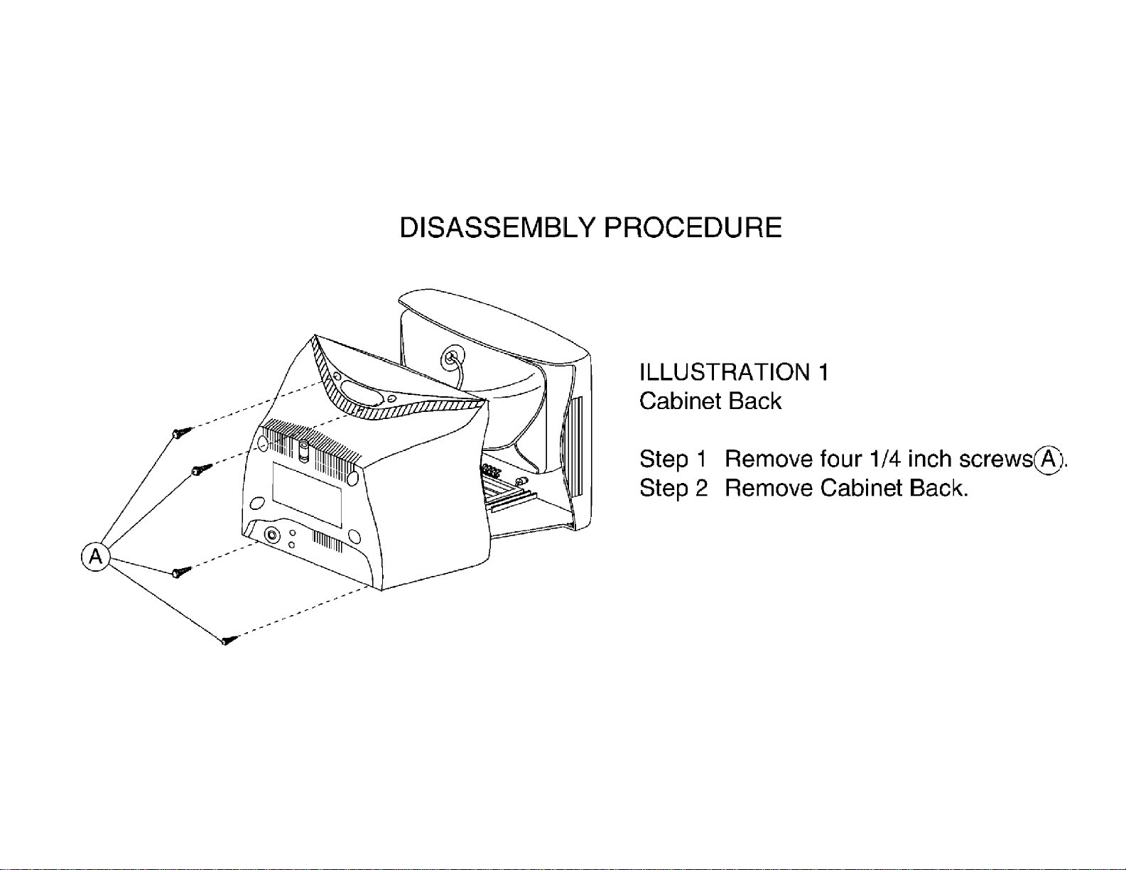
Display Cabinet Back Removal Illustration
Page 31

Display Main Chassis Removal Illustration
Page 32

Display Service Position Illustration
Page 33

Display 13PT30 Disassembly Illustration
Page 34

E8 CHASSIS SERVICE ADJUSTMENTS
REQUIRED TOOLS FOR SERVICING
Isolation Transformer
Multimeter
Oscilloscope
High Voltage (100:1) Oscilloscope Probe
Sencore VG91 Universal Video Generator
Caution: The E8 chassis incorporates a ”hot“ ground system. Always use a separate isolation
transformer when applying power to the exposed chassis.
Service Adjustment Notes:
Unless Otherwise Specified:
1. All service adjustments are ”hot“ voltagewise. For maximum safety, ensure the use of properly insulated
tools.
2. Refer to the E8 Main Chassis Printed Circuit Board for location of test points and adjustable components.
3. Grid Locations (Ex.: D-3) next to the reference numbers for components refer to the Main Chassis Printed
Circuit Board.
Focus Adjustment
1. Tune the set to a local or cable station.
2. Adjust the Focus Control (located on the upper part of the flyback transformer) for best picture details at
high light conditions.
Degaussing the Television
1. Position the television so that the screen faces the direction it will be facing when in use.
2. Ensure the set is turned off.
3. Move a degaussing coil in a circular motion slowly around the sides and front of the set.
4. Withdraw the degaussing coil at least six feet from the television before disconnecting it from its power
source.
Page 35

Service Mode
Introduction
1. There are three service modes used in the E8 chassis. They are:
a. SDM - Service Default Mode
b. SAM - Service Alignment Mode
c. CSM - Customer Service Mode
2. The Service Default Mode (SDM) is a technical aid for the service technician. It is used for setting of
options, reading error codes, and erasing error codes. This mode displays the Run Timer, Software Version,
and current option settings. Service Default Mode (SDM) also establishes a fixed, repeatable setting of
controls to allow measurements to be made. On screen display is kept at a minimum to reduce the cluttering
of wave forms with unwanted information.
3. The Service Alignment Mode (SAM) is used to make tuning adjustments, align the white tone, adjust the
picture geometry, and make sound adjustments.
4. The Customer Service Mode shows error codes and information on the TV operation settings. The servicer
can instruct the customer to enter CSM by telephone and read off the information displayed. This helps the
servicer to diagnose problems and failures in the TV set before making a service call.
5. When in a service mode, "SDM" (for Service Default Mode) or ”SAM“ (for Service Alignment Mode) or
”CSM“ (for Customer Service Mode) will be displayed (in green) in the top right corner of the screen. All
other On Screen Display (except highlighted items in SDM or SAM) will be in red.
6. It will be memorized in the EEPROM that the TV set is in SDM or SAM. This is necessary because the TV
must show up in SDM or SAM again after an ac power interrupt.
7. When the television is in SAM or SDM, all normal features (such as volume control and direct channel
access) are available.
EEPROM Replacement or Defective EEPROM
After replacing a EEPROM (or with a defective/no EEPROM) default settings will be used that enable the set to
start up and that allow access to the Service Default Mode and Service Alignment Mode.
Service unfriendly modes
In the service modes, a number of modes/features are ignored since they interfere with diagnosing or repairing
a set. These are ”service unfriendly modes.“
”Ignoring“ means that the event that is triggered is not executed; the setting remains unchanged (Example:
Timer OFF: 8:00 PM; the set will not switch OFF in service mode at 8:00PM, but the setting will remain).
The service unfriendly modes are:
• (Sleep) timer
• Blue mute
• Auto switch off (when there is no video signal identified)
• Hotel or hospital mode
• Smart lock or blocking by V-chip
• Skipping and/or blanking of ”Not Favorite“ channels
• Automatic storing of Personal Preset settings
• Automatic user menu time-out (menu switches back or OFF automatically)
Page 36

Service Default Mode (SDM)
1. The Service Default Mode (SDM), set the option codes and bytes of the set, and display the error codes
(the Power LED begins blinking procedure for error code display, if errors are detected). SDM also overrides
software protections.
The Service Default Mode (SDM) must be used when taking voltages and waveforms.
2. To enter the Service Default Mode, press the following key sequence on the remote control transmitter:
0-6-2-5-9-6-Menu
Do not allow the display to time out between entries while keying the sequence.
SDM can also be entered by pressing the Channel Down and Volume Down keys on the local keyboard
simultaneously while in SAM mode.
When Service Default Mode is entered, the text "SDM" will be displayed in the upper right corner of the
screen.
3. When Service Default Mode is entered, the Power LED will begin blinking to display any detected error
codes, the set automatically tunes to Channel 3 (61.25 MHz), and service unfriendly modes are disabled. All
customer controls are set to predetermined values.
4. When the unit is operating in Service Default Mode, all normal on-screen displays are suppressed and
replaced by a special service display. A sample SDM display is shown below.
5. To select an option code or option byte in SDM, use the Menu Up or Menu Down keys on the remote
control.
6. To change the value of an option code, use the Menu Left or Menu Right keys.
7. To change the value of an option byte, use the Menu Left or Menu Right keys, or enter the new value using
the numeric keys on the remote control.
8. Press the Status button on the remote control to toggle the OSD (except ”SDM“) ON and OFF to prevent the
OSD from interfering with measurements and oscilloscope waveforms.
9. Press the Menu button on the remote control while in SDM to switch the software to a Virtual Customer
Mode; the text "SDM" will still be displayed in the upper right corner of the screen. In this mode, all customer
menu adjustments to the set can be made. From the Virtual Customer Mode, press the Menu button to
return to the SDM display.
Page 37

10. To exit the Service Default Mode and erase the error codes, turn the unit off with the Power button on the
remote control, then unplug the ac cord.
11. To exit the Service Default Mode and save the error codes, unplug the ac cord to turn off the set. When the
set is turned on again, the Service Default Mode will still be active.
Explanation of Display:
Run Timer
The run timer counts the normal operation hours, not the standby hours. The actual value of the run timer is
displayed in SDM and CSM. The run timer displays hours in hexadecimal format. This display will increment
based on the amount of time the set has been on. The timer will also be incremented one hour each time the set
is turned on.
Software Identification, Cluster, and Version
The software identification, cluster, and version will be shown in the service main menu display.
These numbers consist of the last part of the customer identification printed on the IC package; the screen will
show ”AAABBC-X.Y“. (Example: L90US1 1.2)
− AAA is the engineering project name (Ex: L90 = L9.0).
− BB is a function specification indicating specific functionality or a region (Ex: US). Processors with the same
engineering project name and function name are interchangeable, except for the languages they support.
− C is the language cluster number within the ”BB“ software version (Ex: 1 = English/Spanish/French)
− X is the main version number (Ex: 1)
− Y is the sub version number (Ex: 2)
− the main version number is updated with a major change of specification (incompatible with the previous
software version)
− the sub version number is updated with a minor change (backwards compatible with the previous versions)
− if the main version number changes, the new version number is written in the EEPROM
− if the main version number changes, the default settings are loaded
− if the sub version number changes, the new version number is written in the EEPROM
− if the EEPROM is fresh, the software identification, version and cluster will be written to EEPROM
− Note: a new micro controller is considered to be compatible if it works instead of the old software and the
functionality is not significantly changed.
Error Buffer
Error codes are required to indicate failures in the television. For intermittent complaints, always check the error
buffer. A unique error code is available for:
• activated protection (error codes 1, 2, and 3)
• failing I2C device
• general I2C error
• RAM failure (e.g. internal RAM of microprocessor (IC 7600) )
Other error codes are:
• Signal processor (IC 7250) start-up error
Page 38

• EEPROM check-sum error
General I²C error means: no I²C device is responding to the particular I²C bus.
to GND, SDA short circuit to GND, SCL short
The last five errors, remembered in the EEPROM, are shown in the service menu. This is called the error buffer.
The error that is found last is displayed on the left, except when protection (1 to 3) is active.
Errors 1, 2, and 3 are often shown at the right of the error buffer display whenever they are detected.
Example 1:
Suppose the display shows: 8 – 11 – 2– 0 – 0
With 2 displayed at the right of the error buffer, high beam current protection is active.
Example 2:
Suppose the display shows: 11 – 4 – 5– 3 – 0
With 3 displayed at the right of the error buffer, vertical protection is active.
The following error codes have been defined:
Error Code Table
0 = No error
1 = X-Ray / overvoltage protection active
2 = High beam current (BCI) protection active
3 = Vertical protection active
4 = I²C error while communicating with the sound processor (IC 7803)
5 = Signal processor (IC 7250) start-up error
6 = I²C error while communicating with the signal processor IC (IC 7250)
= General I²C error *
7
8 = Internal RAM error micro controller
9 = EEPROM Configuration error (Checksum error)
10 = I²C error, EEPROM error
11 = I²C error, PLL tuner
Note:
I²C = (SCL/SDA)
*
Possible causes: SCL short circuit
circuit to SDA, SDA open circuit (at IC 7600), SCL open circuit (at IC 7600)
Page 39

Reading Error Codes
Error codes are displayed in the following ways:
1. By SDM display or CSM display
2. By blinking Power LED
1. If the on screen display is working, enter SDM or CSM and read the error buffer display.
2. If the on screen display is not working, do the following:
a. Remove ac power
b. Use a jumper to connect pin 0224 to pin 0228 at IC 7601 (D-3)
c. Apply ac power; read the error codes (see LED Sequence List below)
d. If there is no LED indication, take the following steps as needed:
Power on
Press 0–6–2–5–9–6–Menu on the remote control
Note: Some indications take 30 seconds or longer to appear on the LED.
3. LED Sequence List:
a. Wait for long LED on (1.5 seconds)
b. Count the following on flashes (individual errors are separated by 1.5 seconds LED off)
Example:
Start ( 3 ) ( 2 ) Start
4. Displayed error codes are saved by removing the ac power. Displayed error codes are erased by pressing
the power button on the remote control or local keyboard.
Page 40

Option Code and Status
tes 1 through 7 are used to set 8 options simultaneously with one
The following options in SDM can be identified. Note that not all options may be available in some sets.
OPTION OP VALUES
System SY SS (This option is not used in US models)
Option Byte 1
Option Byte 2
Option Byte 3
Option Byte 4
Option Byte 5
Option Byte 6
Option Byte 7
Slider Bar Value Display DP OFF/ON
Animated Menu AM OFF/ON
Hospital Mode HS OFF/ON
Hotel Mode HT OFF/ON
Demo Mode DM OFF/ON
Games Mode GM OFF/ON
Clock (Volatile) CK OFF/ON
Child Lock CL OFF/ON
V-Chip VC OFF/ON
V-Chip Block Unrated VU OFF/ON
Block No Rating (V-Chip) VN OFF/ON
Smart Sound SS OFF/ON
Smart Picture SP OFF/ON
Remote Control Type RC OFF = RC0702/04 remote control / ON = All other remote controls
Channel Select Time Window TW OFF = 2-second time window / ON = 5-second time window
Surf SF OFF/ON
Video Mute (Channel Change) VM OFF/ON
Tuner Type TN OFF = Philips tuner / ON= ALPS tuner
Fine Tuning FT OFF/ON
AV1 XT OFF/ON
AV2 2X OFF/ON
Auto Cable Detect CD OFF/ON
Blue Mute BM OFF/ON
No Ident (Auto Standby) NI OFF/ON
Noise Reduction NR OFF/ON
Contrast Plus CP OFF/ON
Color Temperature CT OFF/ON
East-West Functions EW OFF/ON (This option is not used in US models)
Video Processor Standby BS OFF/ON
Video Processor Auto Startup AS OFF/ON
Bass/Treble Control/Boost BT OFF/ON
Incredible Surround IS OFF/ON
Volume Limiter VL OFF/ON
Ultra Bass UB OFF/ON
Automatic Volume Leveller (AVL) LV OFF/ON
SAP - Mono/Stereo DU OFF/ON
Audio Out (Fixed/Variable) AO OFF/ON
Sound Type ST BG/I/DK/M (Should remain on M)
Sound Board SB DB = DBX/SAP (BTSC)-EC = BTSC stereo (No SAP)-MA = Mono All-
OB1
OB2
OB3
OB4
OB5
OB6
OB7
Option By
byte (when the option byte is highlighted, the value can be keyed in with
the numerical buttons on remote control or changed with the Menu
Up/Down keys on the remote control). Values = 0 – 255. See the Chassis
Feature Listing to see the values for Option Bytes 1 through 7. These
values can be used to set the option package for a particular model.
MS = Bi Sonic (Mono by tuner, stereo by A/V jacks)
Page 41

Option SY : System
Function: Set the multi system hardware configuration
Values: SS (This option is not used in US models)
OB 1 – OB 7 : Option Byte 1 – Option Byte 7
Function: Set 8 options simultaneously with one byte
(value can be keyed in with numerical buttons on remote control or changed with the Menu Up/
Down keys on the remote control)
Values: 0 – 255
Option DP : Slider Bar Value Display
Function: Enable/disable slider bar value display in customer menu
Values: OFF = Disable slider bar value display
ON = Enable slider bar value display
Option AM : Animated Menu
Function: Enable/disable animated menu
Values: OFF = Disable animated menu display
ON = Enable animated menu display
Option HS : Hospital Mode
Function: Enable/disable the possibility to enter hospital mode
Values: OFF = Disabled, hospital mode cannot be entered
ON = Enabled, hospital mode can be entered
Option HT : Hotel Mode
Function: Enable/disable the possibility to enter hotel mode
Values: OFF = Disabled, hotel mode cannot be entered
ON = Enabled, hotel mode can be entered
Option DM : Demo Mode
Function: Enable/disable the possibility to enter demo mode
Values: OFF = Disabled, demo mode is not active
ON = Enabled, demo mode is active
Option GM : Games Mode
Function: Enable/disable games function
Values: OFF = Disabled, Games command is ignored
ON = Enabled, Games command is processed
Option CK : Clock (Volatile)
Function: Enable/disable clock function
Values: OFF = Disabled, clock menu not available
ON = Enabled, clock menu available
Option CL : Child Lock
Function: Enable/disable child lock function
Values: OFF = Disabled, child lock menu not available
ON = Enabled, child lock menu available
Option VC : V-Chip
Function: Enable/disable v-chip function (customer menu item Smartlock)
Values: OFF = Disabled, v-chip menu (customer menu item Smartlock) not available
ON = Enabled, v-chip menu (customer menu item Smartlock) available
Option VU : V-Chip Block Unrated
Function: Enable/disable V-Chip block unrated (in Smartlock menu)
Values: OFF = Disabled, V-Chip block unrated (in Smartlock menu) not available
ON = Enabled, V-Chip block unrated (in Smartlock menu) available
Page 42

Option VN : Block No Rating (V-Chip)
Function: Enable/disable block no rating V-Chip (in Smartlock menu)
Values: OFF = Disabled, block no rating V-Chip (in Smartlock menu) not available
ON = Enabled, block no rating V-Chip (in Smartlock menu) available
Option SS : Smart Sound
Function: Enable/disable smart sound function
Values: OFF = Disabled, Smart Sound command is ignored
ON = Enabled, Smart Sound command is processed
Option SP : Smart Picture
Function: Enable/disable smart picture function
Values: OFF = Disabled, Smart Picture command is ignored
ON = Enabled, Smart Picture command is processed
Option RC : Remote Control Type
Function: Choose the type of remote control to be used
Values: OFF = RC0702/04 remote control
ON = All other remote controls
Note: If changed when using the RC0702/04, this option can only be returned to the original setting by
option byte correction.
Option TW : Channel Select Time Window
Function: Select time window for channel selection
Values: OFF = 2-second time window for channel selection
ON = 5-second time window for channel selection
Option SF : Surf
Function: Enable/disable the possibility to enter surf mode
Values: OFF = Disabled, customer menu item Surf not available and A/CH command alternates channels
ON = Enabled, customer menu item Surf available and A/CH command surfs or alternates
channels
Option VM : Video Mute (Channel Change)
Function: Enable/disable video mute during channel change
Values: OFF = Disabled, no video mute during channel change
ON = Enabled, video muted during channel change
Option TN : Tuner Type
Function: Choose the tuner type that is configured in the hardware
Values: OFF = Philips tuner (A Philips tuner will have the Philips name embossed on the side)
ON = ALPS tuner (An ALPS tuner will not have the Philips name embossed on the side)
Option FT : Fine Tuning
Function: Enable/disable fine tuning
Values: OFF = Customer menu item fine tuning disabled
ON = Customer menu item fine tuning enabled
Option XT : AV1
Function: Enable/disable external input source 1 (Ext 1)
Values: OFF = Disabled, external input source 1 (Ext 1) not available
ON = Enabled, external input source 1 (Ext 1) available
Option 2X : AV2
Function: Enable/disable external input source 2 (Ext 2)
Values: OFF = Disabled, external input source 2 (Ext 2) not available
ON = Enabled, external input source 2 (Ext 2) available
Page 43

Option CD : Auto Cable Detect
Function: Enable/disable automatic detection of Cable/Broadcast during autostore.
Values: OFF = Disabled, autostore uses the selected Cable/Broadcast setting
ON = Enabled, autostore will detect and set Cable/Broadcast mode
Option BM : Blue Mute
Function: Enable/disable blue mute when no television station signal is present
Values: OFF = Disabled, no blue mute when no television station signal is present
ON = Enabled, blue mute active when no television station signal is present
Option NI : No Ident (Auto Standby)
Function: Enable/disable automatic switch to standby after 10 minutes when no television station signal is
present
Values: OFF = Disabled, no automatic switch to standby
ON = Enabled, set switches to standby after 10 minutes when no television station signal is
present
Option NR : Noise Reduction
Function: Enable/disable noise reduction function
Values: OFF = Disabled, customer menu item Noise Reduction not available
ON = Enabled, customer menu item Noise Reduction available
Option CP : Contrast Plus
Function: Enable/disable contrast plus function
Values: OFF = Disabled, customer menu item Contrast Plus not available
ON = Enabled, customer menu item Contrast Plus available
Option CT : Color Temperature
Function: Enable/disable color temperature function
Values: OFF = Disabled, customer menu item Color Temperature not available
ON = Enabled, customer menu item Color Temperature available
Option EW : East-West Functions
Function: Enable/disable east-west control function (This option is not used in US models)
Values: OFF = Disabled, east-west alignment not available in SAM (EWW, EWP, EWC, EWT)
ON = Enabled, east -west alignment available in SAM (EWW, EWP, EWC, EWT)
Option BS : Video Processor Standby
Function: Enable/disable video processor standby
Values: OFF = Disabled, video processor standby is not active
ON = Enabled, video processor standby is active
Option AS : Video Processor Auto Startup
Function: Enable/disable video processor auto-startup
Values: OFF = Enabled, video processor is in auto-startup mode
ON = Disabled, video processor is switched on under control of microcontroller
Option BT : Bass/Treble Control/Boost
Function: Enable/disable bass and treble function
Values: OFF = Disabled, customer menu items Bass and Treble not available
ON = Enabled, customer menu items Bass and Treble available
Option IS : Incredible Surround
Function: Enable/disable incredible surround function
Values: OFF = Disabled, incredible surround function not available
ON = Enabled, incredible surround function available
Option VL : Volume limiter
Function: Enable/disable volume limiter
Values: OFF = Disabled, customer menu item Volume Limiter not available
ON = Enabled, customer menu item Volume Limiter available
Page 44

Option UB : Ultra Bass
Function: Enable/disable ultra bass function
Values: OFF = Disabled, ultra bass function not available
ON = Enabled, ultra bass function available
Option LV : Automatic Volume Leveller (AVL)
Function: Enable/disable automatic volume leveller function
Values: OFF = Disabled, customer menu item AVL not available
ON = Enabled, customer menu item AVL available
Option DU : SAP
Function: Set SAP configuration (sets with DBX stereo system only)
Values: OFF = Disabled, stereo/SAP not available
ON = Enabled, stereo/SAP available
Option AO : Audio Out (Fixed/Variable)
Function: Set audio output type (where present)
Values: OFF = Fixed audio out
ON = Variable audio out (always on)
Option ST : Sound Type
Function: Set the sound type
Values: BG PAL system
I PAL system
DK PAL system
M Default for USA
Option SB : Sound Board
Function: Set the sound board configuration
Values: DB = DBX/SAP (BTSC)
EC = BTSC stereo (No SAP)
MA = Mono All
MS = BiSonic (Mono from tuner, Stereo from A/V jacks)
Page 45

Service Alignment Mode (SAM)
1. The Service Alignment Mode (SAM) is used to make tuning adjustments, align the white tone, adjust the
picture geometry, and make sound adjustments.
2. To enter the Service Alignment Mode (SAM), press the following key sequence on the remote control
transmitter: 0-6-2-5-9-6-Status
Do not allow the display to time out between entries while keying the sequence.
SAM can also be entered by pressing the Channel Down and Volume Down keys on the local keyboard
simultaneously while in SDM mode. When Service Alignment Mode is entered, the text "SAM" will be
displayed in the top right corner of the screen.
3. When Service Alignment Mode is entered, service unfriendly modes are disabled.
The following volatile SAM item values are set:
♦ AKB = 0
♦ VSD = 0
♦ AFW = 275 kHz
♦ SBL = 0
4. When the unit is operating in Service Alignment Mode, all normal on-screen displays are suppressed and
replaced by a special service display. The first screen seen upon entering SAM is the ”top level SAM
menu.“ The service technician must return to the top level SAM menu before exiting with a power-off
command. A sample SAM top level menu display is shown below.
Explanation of top level SAM menu display:
The Software Identification, Cluster, and Version are explained in the Service Default Mode section
under ”Explanation of Display.“
The Menu Items and Sub Menus are explained below.
Note: The ”Audio“ sub menu will not be seen on screen when Service Alignment Mode is first
entered. Use the Menu Up and Menu Down buttons on the remote control to view all menu
items and sub menu choices.
5. To select a menu item or a sub menu in SAM, use the Menu Up or Menu Down keys on the remote control
to highlight the item or menu you wish to adjust.
Page 46

6. To change the value of a highlighted SAM menu item (AKB or VSD), use the Menu Left or Menu Right keys
on the remote control.
7. To enter a highlighted SAM sub menu, use the Menu Left or Menu Right keys.
After entering the sub menu, use the Menu Up or Menu Down to select an item within the sub menu.
Use the Menu Left or Menu Right keys to change the value of the selected item.
Press the Menu button to return to the top level SAM menu.
8. Press the Menu button on the remote control while in SAM to switch the software to a Virtual Customer
Mode; the text "SAM" will still be displayed in the upper right corner of the screen. In this mode, all customer
menu adjustments to the set can be made. From the Virtual Customer Mode, press the Menu button to
return to the SAM Menu.
9. Press the Status button on the remote control to toggle the OSD (except ”SAM“) ON and OFF.
10. To exit the Service Alignment Mode, turn the set off with the Power button on the remote control. To turn off
the set without exiting SAM (or erasing any stored error codes), unplug the ac cord. When the set is
powered on again, the Service Alignment Mode will still be active.
Note: When SAM is exited or a power interrupt occurs, the volatile SAM items AKB, VSD, AFW, and SBL
will be reset to their original values.
Main Menu
The SAM main menu contains the following items:
− AKB
− VSD
− Tuner sub menu
− White Tone sub menu
− Geometry sub menu
− Audio sub menu (on stereo chassis)
Menu: MAIN Values Remarks
AKB Black current loop
(Auto Kine Bias)
VSD Vertical scan
disable
TUNER
WHITE TONE
GEOMETRY
AUDIO
OFF/ON (0/1)
OFF/ON (0/1)
>
>
>
>
Available only on stereo chassis
Page 47

Tuner sub menu
The tuner sub menu contains the following items:
− IF-PLL
− AFW
− AGC
− YD
− CL
− AFA and AFB
The items AFA and AFB cannot be selected, they are for monitoring purposes only.
The item values are stored in EEPROM if this sub menu is left.
A sample display of the Tuner sub menu is shown below.
Tuner Adjustment:
Sub Menu: TUNER Values Remarks
IF-PLL IF-PLL alignment 0 – 127 This adjustment is auto-aligned (no action required)
AFW AFC window 125/275 kHz Always set to 275 kHz
AGC AGC takeover point 0 – 63 See below
YD Y-delay adjustment 0 – 15 Always set to 12 (no effect)
CL Cathode drive level 0 – 7 Always set to 4
AFA 0 / 1 read only, not accessible
AFB 0 / 1 read only, not accessible
Page 48

AGC Takeover Point (AGC):
1. Enter the Service Alignment Mode (SAM) by pressing the following key sequence on the remote control
transmitter:
0-6-2-5-9-6-Status
Do not allow the display to time out between entries while keying the sequence.
2. From the top level SAM menu, use the Menu Up/Down keys to highlight the Tuner sub menu.
3. Use the menu left/right keys to enter the Tuner sub menu.
4. In the Tuner sub menu, use the Menu Up/Down keys to highlight AGC.
5. Use the Menu Right key to raise the value of AGC until snow appears in the picture.
6. Then use the Menu Left/Right keys to reduce AGC value until the snow disappears.
a. AGC values between 10 and 20 are nominal.
b. Single digit AGC values may cause overload.
7. Upon completion of Tuner adjustment, press the Menu button to return to the top level SAM menu.
White Tone sub menu
The white tone sub menu contains the following items:
− Normal Red
− Normal Green
− Normal Blue
− Delta Cool Red
− Delta Cool Green
− Delta Cool Blue
− Delta Warm Red
− Delta Warm Green
− Delta Warm Blue
Note: Delta values are only used in models with the item ”Color Temperature“ in the customer menu.
OSD is kept to a minimum in this menu, in order to make white tone alignment possible.
The item values are stored in EEPROM if this sub menu is left.
The Contrast Plus feature (black stretch) is set to OFF when the White Tone sub menu is entered.
A sample display of the White Tone sub menu is shown below.
Page 49

Sub Menu: WHITE TONE Value Range Remarks
f the normal values.
These start at the default values, and are set to
achieve cool and warm steps of color temperature in
Standard factory settings are given as the default
NORMAL Starting Values:
NORMAL RED 0 – 63 32
NORMAL GREEN 0 – 63 23
NORMAL BLUE 0 – 63 25
COOL
DELTA COOL RED
DELTA COOL
GREEN
DELTA COOL
BLUE
WARM
DELTA WARM
RED
DELTA WARM
GREEN
DELTA WARM
BLUE
Default Value
0 Delta values are a change o
+1
+7
0
-4
-12
the customer menu.
values.
White Tone Adjustments:
Note: The following procedure was performed with a Sencore VG91 Universal Video Generator providing grey
scale bars.
1. Enter the Service Alignment Mode (SAM) by pressing the following key sequence on the remote control
transmitter:
0-6-2-5-9-6-Status
Do not allow the display to time out between entries while keying the sequence.
2. From the top level SAM menu, use the Menu Up/Down keys to highlight the White Tone sub menu.
3. Use the Menu Left/Right keys to enter the White Tone sub menu.
4. Set the VG91 Generator as follows: STD TV Ch. 3, RF-IF Range set to HI, RF-IF Level set to NORMAL (1),
Video Pattern = Raster, R-G-B raster controls OFF.
5. Connect the RF output of the generator to the Television Antenna Input, and adjust the VG91 level to
remove any snow from the raster.
6. Turn off chroma at generator and leave grey scale bars.
7. From the White Tone sub-menu, use the Menu Up/Down keys to select Normal Red, Normal Green, or
Normal Blue. Then use the Menu Left/Right keys to adjust the values to obtain the best white balance.
8. A reasonable starting point for NORMAL is:
Normal Red=37, Normal Green=33, Normal Blue=35
9. After NORMAL is set, use the same method to set DELTA COOL and DELTA WARM as offsets.
A reasonable starting point for DELTA COOL is:
Delta Cool Red=0, Delta Cool Green=+1, Delta Cool Blue=+3
A reasonable starting point for DELTA WARM is:
Delta Warm Red=0, Delta Warm Green=-6, Delta Warm Blue=-5
10. After the values are set, or if no changes are required, press Menu to return to the top level SAM menu.
Page 50

Geometry sub menu
OSD is kept to a minimum in this sub menu in order to make picture geometry adjustments possible.
The item values are stored in EEPROM if this sub menu is left.
The value of item Service Blanking (SBL) is not stored in EEPROM, and it is set to OFF when the geometry sub
menu is exited.
A sample display of the Geometry sub menu is shown below.
The picture geometry sub menu contains the following items:
Sub Menu:
VAM
VSL Vertical slope 0 – 63
SBL Service blanking ON/OFF
HSH Horizontal shift 0 – 63
EWW E-W width 0 – 63 Not used
EWP E-W parabola/width 0 – 63 Not used
EWT E-W trapezium 0 – 63 Not used
EWC E-W corner parabola 0 – 63 Not used
H60 Delta HSH for 60 Hz 0 – 15 Not used
V60 Delta VAM for 60 Hz 0 – 15 Not used
VSC Vertical S-Correction 0 – 63
VSH Vertical shift 0 – 63
GEOMETRY
Vertical amplitude
Values
0 – 63
Remarks
Page 51

Geometry Adjustments:
Notes:
1. The following Geometry adjustments were performed with a Sencore VG91 Universal Video Generator.
2. Set the VG91 Generator as follows: STD TV Ch. 3, RF-IF Range set to HI, RF-IF Level set to NORMAL (1),
Video Pattern = Raster, R-G-B raster controls OFF, crosshatch or center cross pattern as required.
3. Connect the RF output of the generator to the Television Antenna Input, and adjust the VG91 level to
remove any snow from the raster.
Vertical Shift (VSH):
1. Enter the Service Alignment Mode (SAM) by pressing the following key sequence on the remote control
transmitter:
0-6-2-5-9-6-Status
Do not allow the display to time out between entries while keying the sequence.
2. From the top level SAM menu, use the Menu Up/Down keys to highlight the Geometry sub menu.
3. Use the Menu Left/Right keys to enter the Geometry sub menu.
4. In the Geometry sub-menu, use the Menu Up/Down buttons to select VAM.
5. Input a center cross pattern to the antenna/cable input terminal.
6. Using the Menu Left/Right keys, adjust VSH so that the horizontal bar is properly centered, top to bottom.
7. If other Geometry adjustments are needed, proceed to the necessary adjustment using the Menu Up/Down
buttons.
8. Upon completion of Geometry adjustments, press the Menu button to return to the top level SAM menu.
Vertical Amplitude (VAM):
1. Enter the Service Alignment Mode (SAM) by pressing the following key sequence on the remote control
transmitter:
0-6-2-5-9-6-Status
Do not allow the display to time out between entries while keying the sequence.
2. From the top level SAM menu, use the Menu Up/Down keys to highlight the Geometry sub menu.
3. Use the Menu Left/Right keys to enter the Geometry sub menu.
4. In the Geometry sub-menu, use the Menu Up/Down buttons to select VAM.
5. Input a crosshatch pattern to the antenna/cable input terminal.
6. Using the Menu Left button, reduce the value so that the picture does not fill the entire screen.
7. Use the Menu Up/Down keys to select VSH (Vertical Shift) from the Geometry sub-menu and, using the
Menu Left/Right keys, center the picture on the screen, top to bottom.
8. Using the cursor up/down keys, select VAM from the Geometry sub-menu, and use the Menu Right key to
increase the value to obtain a slight overscan.
9. If other Geometry adjustments are needed, proceed to the necessary adjustment using the Menu Up/Down
buttons.
10. Upon completion of Geometry adjustments, press the Menu button to return to the top level SAM menu.
Page 52

Horizontal Shift (HSH):
Note: This adjustment centers the video on the raster. It does not move the raster.
1. Enter the Service Alignment Mode (SAM) by pressing the following key sequence on the remote control
transmitter:
0-6-2-5-9-6-Status
Do not allow the display to time out between entries while keying the sequence.
2. From the top level SAM menu, use the Menu Up/Down keys to highlight the Geometry sub menu.
3. Use the Menu Left/Right keys to enter the Geometry sub menu.
4. In the Geometry sub-menu, use the Menu Up/Down buttons to select HSH.
5. Input a center cross pattern to the antenna/cable input terminal.
6. Using the Menu Left/Right keys, adjust HSH so that the vertical bar is properly centered, left to right.
7. If other Geometry adjustments are needed, proceed to the necessary adjustment using the Menu Up/Down
buttons.
8. Upon completion of Geometry adjustments, press the Menu button to return to the top level SAM menu.
Vertical Slope (VSL):
1. Enter the Service Alignment Mode (SAM) by pressing the following key sequence on the remote control
transmitter:
0-6-2-5-9-6-Status
Do not allow the display to time out between entries while keying the sequence.
2. From the top level SAM menu, use the Menu Up/Down keys to highlight the Geometry sub menu.
3. Use the Menu Left/Right keys to enter the Geometry sub menu.
4. In the Geometry sub-menu, use the Menu Up/Down buttons to select VSL.
5. Input a crosshatch pattern to the antenna/cable input terminal.
6. Using the Menu Left/Right keys, adjust VSL so that the squares at the bottom of the screen are equal in
size to the squares at the top of the screen.
7. If other Geometry adjustments are needed, proceed to the necessary adjustment using the Menu Up/Down
buttons.
8. Upon completion of Geometry adjustments, press the Menu button to return to the top level SAM menu.
Vertical S-Correction (VSC):
1. Enter the Service Alignment Mode (SAM) by pressing the following key sequence on the remote control
transmitter:
0-6-2-5-9-6-Status
Do not allow the display to time out between entries while keying the sequence.
2. From the top level SAM menu, use the Menu Up/Down keys to highlight the Geometry sub menu.
3. Use the Menu Left/Right keys to enter the Geometry sub menu.
4. In the Geometry sub-menu, use the Menu Up/Down buttons to select VSC.
5. Input a crosshatch pattern to the antenna/cable input terminal.
6. Using the Menu Left/Right keys, adjust VSC so that the squares at the center of the screen are equal in size
to the squares at the top and bottom of the screen.
7. If other Geometry adjustments are needed, proceed to the necessary adjustment using the Menu Up/Down
buttons.
8. Upon completion of Geometry adjustments, press the Menu button to return to the top level SAM menu.
Page 53

Service Blanking (SBL):
Service Blanking provides a straight cutoff line in the center of the raster. It is useful when centering the raster.
It can also be used in adjusting the yoke and setting vertical size and linearity.
1. Enter the Service Alignment Mode (SAM) by pressing the following key sequence on the remote control
transmitter:
0-6-2-5-9-6-Status
Do not allow the display to time out between entries while keying the sequence.
2. From the top level SAM menu, use the Menu Up/Down keys to highlight the Geometry sub menu.
3. Use the Menu Left/Right keys to enter the Geometry sub menu.
4. In the Geometry sub-menu, use the Menu Up/Down buttons to select SBL.
5. Use the Menu Left/Right keys to toggle SBL ON or OFF.
6. With SBL on, VSH can be used to center the raster on the fiduciary marks (the small notches in the
phosphor on the right and left edge of the CRT). These are absolute center.
7. If other Geometry adjustments are needed, proceed to the necessary adjustment using the Menu Up/Down
buttons.
8. Upon completion of Geometry adjustments, press the Menu button to return to the top level SAM menu.
Delta HSH for 60Hz (H60):
Note: This adjustment should not be changed from the factory preset value (10).
Delta VAM for 60Hz (V60):
Note: This adjustment should not be changed from the factory preset value (5).
Audio sub menu
The audio sub menu item values are stored in EEPROM if this sub menu is left.
A sample display of the Audio sub menu is shown below.
The Audio sub menu contains the following item on stereo chassis:
Sub Menu: AUDIO Values Remarks
AT Attack time at AVL 1 – 4 Normal setting is 4.
Page 54

Audio Adjustment:
Attack Time at AVL (AT):
1. Enter the Service Alignment Mode (SAM) by pressing the following key sequence on the remote control
transmitter:
0-6-2-5-9-6-Status
Do not allow the display to time out between entries while keying the sequence.
2. From the top level SAM menu, use the Menu Up/Down keys to highlight the Audio sub menu.
3. Use the Menu Left/Right keys to enter the Audio sub menu.
4. Use the Menu Left/Right keys to adjust the value of AT.
5. Set the volume of AT to 4.
6. Upon completion of Audio adjustment, press the Menu button to return to the top level SAM menu.
Convergence and Purity Adjustments
Notes:
1. The following adjustments were performed with a Sencore VG91 Universal Video Generator.
2. Set the VG91 Generator as follows: STD TV Ch. 3, RF-IF Range set to HI, RF-IF Level set to NORMAL (1),
Video Pattern = Raster, R-G-B raster controls OFF, Mode Switch set to L+R, Audio Frequency set to
300Hz, and 0 Pilot (max. CCW).
3. Connect the RF output of the generator to the Television Antenna Input, and adjust the VG91 level to
remove any snow from the raster.
Pre-Convergence Procedure
Note: The degaussing procedure should be performed prior to this adjustment.
1. Place the multi-pole Purity and Convergence Assembly with the 2-Y pole purity rings directly in the gap
between the G2 and G3 (focus) grids as shown in the Convergence and Purity Assembly.
Page 55

2. Enter Service Alignment Mode (refer to Service Alignment Mode section).
3. Apply a center cross or crosshatch pattern to the antenna/cable input terminal.
4. Select the White Tone sub-menu by pressing the Menu Up/Down keys on the remote control so that White
Tone is highlighted.
5. Use the Menu Left/Right keys to enter the White Tone sub-menu.
6. Use Menu Up/Down keys to toggle between the options. Be sure to record the values of all options (Normal
Red/Green/Blue, Delta Cool Red/Green/Blue, and Delta Warm Red/Green/Blue).
7. Use the Menu Up/Down keys to select Normal Green, and use the Menu Left key to set Normal Green to
minimum.
8. Loosen the yoke clamp screw, pull the yoke back, and remove the three yoke wedges.
9. Slide the yoke all the way forward so that it rests against the bell of the CRT.
10 Tighten the yoke clamp screw so that the yoke does not drop away from the bell of the CRT.
11. Slowly spread, and if necessary, rotate the 2-Y pole purity rings so that the red and blue lines are at least
parallel and preferably coincide at the 6:00 and 12:00 positions as shown in the following linked graphic "2Y
Spread and 2X Rotate".
12. Proceed to the Color Purity Adjustment.
Page 56

Color Purity Adjustment
1. Connect a solid white pattern signal to the antenna/cable input terminal.
2. Use the Menu Up/Down keys to select Normal Blue, and use the Menu Left key to set Normal Blue to
minimum.
3. Use the Menu Up/Down keys to select Normal Red, and use the Menu Right key to set Normal Red to
maximum.
4. Slowly spread the 2-X pole purity rings to center the red portion of the screen, leaving the same amount of
green on one side of the screen as blue on the other side.
5. Tighten the yoke clamp screw slightly so that the yoke may be moved with some friction.
6. Proceed to the Static Center Convergence Adjustment.
Static Center Convergence Adjustment
1. Apply a center cross or crosshatch pattern to the antenna/cable input terminal and observe the screen to
ensure that the yoke is not tilted. If necessary, rotate the yoke to obtain a level raster.
2. Use the Menu Up/Down keys to select Normal Blue, and use the Menu Right key to set Normal Blue to
maximum.
3. Slowly spread, and if necessary, rotate the 4-pole magnetic rings to converge red and blue lines at the
center of the screen.
4. Use the Menu Up/Down keys to select Normal Green, and use the Menu Right key to set Normal Green to
maximum.
7. Slowly spread, and if necessary, rotate the 6-pole magnetic rings to converge red/blue on green lines at the
center of the screen.
8. Repeat steps three and five for optimum performance.
9. Proceed to the Dynamic Edge Convergence Adjustment.
Dynamic Edge Convergence Adjustment
Page 57

Note: To secure the correct position of the deflection yoke, three rubber wedges are used. They are ultimately to
be placed as shown in Figure 3c or Figure 4c.
1. Apply a crosshatch pattern to the antenna/cable input terminal.
2. Use the Menu Up/Down keys to select Normal Green, and use the Menu Left key to set Normal Green to
minimum.
3. Tilt the yoke up and down to converge the red and blue vertical lines at the 6:00 and 12:00 positions and the
red and blue horizontal lines at the 3:00 and 9:00 positions (refer to Figure 5). When the correct position has
been found, place a rubber wedge between the yoke and the CRT. If the yoke is tilted up, place wedge one
as shown in Figure 3a; if it is tilted down, place wedge one as shown in Figure 4a.
4. Tilt the yoke to the left and right to find the point of best possible convergence of the red and blue lines at
the edges, top and bottom of the screen as shown in Figure 6. When the correct position is located, place
wedges two and three as shown in Figure 3b or Figure 4b.
5. Remove wedge one and place it in the final position as shown in Figure 3c or Figure 4c.
6. Use the Menu Up/Down keys to select Normal Green, and use the Menu Right key to set Normal Green to
maximum.
7. Proceed to the White Balance Setup.
Page 58

Master Screen (VG2)/ White Balance Setup:
1. With the set OFF, rotate VG2 (located on the lower part of the flyback transformer) counter clockwise.
2. Use the Power Button (on the remote control or the local keyboard) to turn the set ON, without a signal, and
rotate VG2 clockwise until snow is visible.
3. Enter Service Alignment Mode (refer to Service Alignment Mode section).
4. Enter the Virtual Customer Menu by pressing the Menu button on the remote and set brightness and picture
to 31 and color to 0.
5. Apply an NTSC color bar signal to the antenna/cable input terminal and tune to the active channel.
6. Connect an oscilloscope, 20V per division and 10uSec time base, to pin 6 of the CRT Socket. Observe the
stairstep pattern while adjusting VG2.
Hint: Counter clockwise adjustment will compress bottom of stairstep pattern. Clockwise adjustment will
compress top of stairstep pattern.
7. Adjust VG2 midway between top and bottom compression.
8. Proceed to White-Tone Adjustments under White Tone sub-menu in the Service Alignment Mode section to
complete White Balance Setup.
Customer Service Mode (CSM)
1. The Customer Service Mode (CSM) is used to retrieve data on the TV operation settings and stored error
codes.
2. To enter the Customer Service Mode, press and hold the Mute button on the remote control and any key on
the local keyboard (except ”Power“) for more than 4 seconds. When the set is in Customer Service Mode,
the text "CSM" is displayed in the top right corner of the screen.
3. To use this system, the customer is instructed to enter CSM and read off the display that appears. This
information is useful to gain insights into failures before traveling to the customer's home.
4. This information can also be used to avoid nuisance trips to the home when the problem is an operational
error (example: Closed Caption is on or set is in Hospital Mode).
5. When entering CSM, all disruptive functions are turned off, and service unfriendly modes are ignored. While
CSM is active, no changes can be made in settings or functions. When CSM is exited, the TV returns to all
prior operational settings.
6. To exit CSM, press any key (on the remote control or local keyboard) except ”Channel Up“ or ”Channel
Down.“
To exit CSM and return the set to normal operation mode, press any key on the local keyboard or the remote
control except Channel Up, Channel Down, or Power.
To exit CSM and turn the set off, press the Power button on either the TV set or the remote control.
7. A sample CSM display is shown below.
Page 59

Explanation of CSM Display Screen
The following information is displayed on screen:
• Text ”CSM“ on the first line
• Line number for every line (to make CSM language independent)
• To view multiple CSM pages (such as lines 8 and 9), use the Channel Up or Channel Down keys
• For more information on lines 1, 2, and 3, see SDM section ”Explanation of Display“
• Line 1 displays the run timer and the software identification, cluster, and version
• Line 2 displays the error buffer contents (the word ”error“ is not used on this screen, instead ”codes“ is used)
• Line 3 displays the option code information
• Line 4 displays SYS: (This is not used)
• Lines 5 through 8 display information on active service unfriendly modes
• Line 5 displays the text ”NOT TUNED“ if no television station is tuned
• Line 6 displays the text ”TIMER“ if the sleep timer or ”on“ timer is active
• Line 7 displays the text ”LOCKED“ if one or more channels or presets is locked via child lock
• Line 8 displays the text ”HOSPITAL“ if hospital mode is active, or ”HOTEL“ if hotel mode is active
• If the volume limiter is active, line 9 displays the text ”VOL LIM“ and the set value of the volume limiter. If the
volume limiter is inactive, the displayed value will be 255 (the maximum volume allowed).
Page 60

CSM Flow Chart
any key on the local keyboard
when the set is switched on,
picture, sound and feature
Normal operation mode
Press "MUTE" button (RC) and
(except "POWER") for more than 4 seconds
Store current picture, sound and
feature settings (for later retrieval)
Set pre-defined picture, sound and
feature settings
Ignore service unfriendly options
Display CSM information screen
Exit CSM
Restore picture, sound and
stored during entry)
"Channel up"
(RC or local
keyboard)
Other key
"Channel down"
(RC or local
keyboard)
“POWER”
(RC or local
keyboard)
To next CSM pageTo previous CSM page
Off (Exit CSM):
settings (that were stored
during entry) are restored
Page 61

E8 CHASSIS INTRODUCTION
The E8 series chassis is the Small Screen TV chassis produced by Philips Consumer Electronics Company
for the 1999-2000 model year. The E8 is used with 13, 19, and 20 inch CRT’s. The E8 Tuning System
features a 181 channel Tuning System with On-Screen Display. The Tuning System uses two IC’s mounted
on the main chassis. It consists of a Microcomputer IC and Memory IC. The Microcomputer communicates
with the Memory IC, the Customer Keyboard, the Remote Receiver, the U/V Tuner, the TV Signal Processor,
the Stereo Decoder (optional), and the Power On-Off circuitry. The Memory IC retains the settings for
favorite stations, customer control settings, feature settings, and factory setup data.
The chassis features a Very Large Scale Integration (VLSI) IC for TV Signal Processing. This IC performs
Video IF, Sound IF, AFT/AGC control, Horizontal Signal Processing, Vertical Signal Processing,
Horizontal/Vertical Synchronization, Chroma/Luminance Processing, and Video Switching between internal
and external inputs. On-Screen Graphics from the Microcomputer are placed on the main signal within the
TV Signal Processor. Automatic Volume Level (AVL) from the Microcomputer is sent to the TV Signal
Processor (Mono Sets) and to the Stereo Module (DBX Stereo Sets via the I2C bus). AVL for Normal Stereo
is switched by Pin 9 of the Microcomputer, 7600. The Mono version has a 1 watt audio amplifier. The
Normal Stereo version has a 2x1 watt amplifier. The DBX Stereo version has a 2x3 watt amplifier. Latin
American versions of this chassis may have a 2 or 3 watt Mono amplifier.
The E8 chassis features a Switching Mode Power Supply. A ”HOT“ ground reference is used in the primary
side of the power supply. ”COLD“ (signal) ground is used from the secondary of the power supply and
throughout the rest of the chassis. AN ISOLATION TRANSFORMER IS REQUIRED WHEN DOING
SERVICE ON ANY CHASSIS.
Page 62

SIGNAL FLOW
The incoming TV RF signal is applied to the U/V Tuner via the Antenna and RF input. The 45.75MHz IF
signal is developed within the U/V Tuner, then amplified by an IF Preamplifier located inside the Tuner. The
amplified IF signal is sent from Pins 10 and 11 of the U/V Tuner to the SAW filter, 1003. The SAW filter
produces bandpass shaping for the IF signal before it is applied to the TV Signal Processing Integrated
Circuit, 7250 for processing. AFT voltage is developed within 7250. These voltage values are then sent to
the microcomputer via the I2C bus for Tuner Oscillator frequency correction.
Sound IF signal processing for the E8 chassis is performed by coupling the 4.5MHz Sound IF signal from
7250 Pin 6 through transistor 7266 and a 4.5MHz band pass filter 1001 to Pin 1 of 7250. In the Mono
version, Baseband Audio from Pin 15 of 7250 is buffered by transistor 7951 before being applied to Bass
and Treble circuits. The outputs of the Base and Treble circuits are applied to a 1 watt amplifier 7954 in the
US version or a 2 or 3 watt amplifier 7953 in the Latin version. In sets equipped with a Stereo module,
Baseband Audio from Pin 15 of 7250 is fed to the Stereo Decoder module. The DBX Stereo Decoder
module has internal/external switching, AVL switching, volume control, and alignment settings via the I2C
bus (SDA & SCL). Internal/external switching, AVL switching, and volume control for the Normal Stereo
module are performed through individual control lines from the Microcomputer. Audio output amplifiers for
both the DBX and Normal Stereo versions are located on the Stereo module. AVL switching for the Mono
version is performed in 7250 via the I2C bus. Volume for the Mono set is controlled in the Audio Output
Page 63

Amplifier 7954 or 7953 by a control line from the Microcomputer 7600 Pin 2. Volume for the Normal Stereo
is controlled in the Stereo Module by a control line from the Microcomputer 7600 Pin 2. Volume control for
the DBX Stereo is controlled in the Stereo Module by the Microcomputer via the I2C bus.
Composite Video from Pin 6 of 7250 is buffered by 7266 and sent to 1200, a 4.5MHz trap, to remove any
sound. The Video is then applied to Pin 13 of 7250. The Internal/External switch selects between Pin 13 or
the External Video source on Pin 17. The selected Video is fed to an internal Y/C separator inside 7250.
Luminance and Chroma is fed to an internal SVHS switch which selects between internal Y/C or external
Y/C on Pins 11 and 10. Internally selected ”C“ Chroma is fed to an internal Demodulator which outputs R-Y
and B-Y on Pins 30 and 29. Internally selected ”L“ Luminance is output on Pin 28. R-Y, B-Y, and ”L“ are fed
to the Matrix circuit on Pins 31, 32, and 27.
Red, Green, and Blue On-Screen display signal from the Microcomputer 7600 Pins 34, 33, and 32 are fed to
the Signal Processor 7250 Pins 23, 24, and 25. Fast Blanking from 7600 Pin 35 is fed to 7250 Pin 26.
Brightness, Picture, Sharpness, Color, and Tint control voltages are developed within 7250 from the Tuning
System Microcomputer 7600 via the I2C bus. The Red, Green, and Blue signals developed by the signal
processor, 7250, are output on Pins 21, 20, and 19 and applied to the CRT board. On the CRT board, these
signals are amplified before being applied to the CRT.
The White Balance controls for the CRT set-up are controlled within 7250 by the Microcomputer via the I2C
bus. Adjustments are performed with the set in the Service Test Mode. Always use the procedures in the
Service Manual for setting up the CRT circuits (White Balance). The White Balance is set by adjusting the
White Tone adjustments in the Service Test Mode.
Horizontal and Vertical signals are also developed within 7250. Adjustment for Horizontal and Vertical
Geometry are done with the Remote Transmitter via the Service Test Mode. There is no adjustment for the
Horizontal Oscillator. The Horizontal circuit is a count down type of system that gets its base frequency from
the 3.58MHz circuit.
When the set is turned On, the Low on Pin 19 of 7600 is removed allowing the On/Standby line to go High.
The High is applied to 7607, the Astable Multivibrator, which is powered by the +5VD supply. The Astable
Multivibrator 7607 provides Horizontal Drive to drivers 7608 and 7400. The drive is then applied to 7402, the
Horizontal Output transistor, which drives the Horizontal Deflection Yoke and the IFT. The IFT develops
high voltage, focus voltage, and filament voltage for the CRT. Scan derived voltages produced by the IFT
are 160 volts, VLOTAUX13V 13 volts, -13 volts, VLOTAUX5V 5 volts, and VLOT8V 8 volts. The scan
derived VLOT8V 8 volt supply produces the +8VA supply which is applied to Pin 37 of 7250 to power the
Horizontal and Vertical sections of the IC. The Horizontal Oscillator section of 7250 does not operate until
the Scan circuit is working. Horizontal Drive on Pin 40 is applied to 7607 to synchronize the Astable
Multivibrator to the correct frequency.
The Shutdown circuits of the set monitor for excessive Beam Current, excessive High Voltage, or a Low +13
volt supply (VLOTAUX13V). The BCL_PROTN circuit of the IFT monitors for excessive Beam Current. If
the BCL_PROTN line goes High, transistor 7611 will turn On causing Pin 16 of 7600 to go Low, turning the
set Off. Transistors 7403 and 7404 monitor the secondary of the IFT for excessive voltage. If the output of
the IFT should go too high, the HEW_PROTN line will go High, causing Pin 50 of 7250 to go High. This will
shut the Horizontal Oscillator Off. Transistor 7621 and Zener Diode 6612 monitors the 13 volt
(VLOTAUX13V) line. If the 13 volt supply should go Low or fail, 7621 will turn On causing Pin 16 of 7600 to
go Low, turning the set Off. Transistor 7620 provides a power On delay for this circuit.
Page 64

E8 CHASSIS POWER SUPPLY BLOCK
When a 120Vac source is connected to the E8 chassis, approximately 160Vdc is developed by the bridge
rectifier circuit. The 160 volts dc goes through 5545 to the FET switch. The start voltage for the switching
mode power supply is taken from the hot leg of the input ac.
The power supply includes a single integrated circuit, operating as a free-running switching mode power
supply. The frequency of operation varies with the circuit load. There is no separate power supply for
standby; instead, the power supply turns On when ac is applied. The switching regulator IC starts switching
when the initial voltage is applied through the start circuit. Inside the switching regulator, the drive circuit
turns the FET switch On and Off to allow current to flow through the primary of the transformer 5545. Energy
stored in the primary during the On-time is delivered to the secondaries during the Off-time. Feedback from
the Hot secondary is used to control the switching regulator. Positive voltage from the hot secondary is
rectified to provide B+ for the switching regulator. The voltages needed to operate the television are
developed from the secondaries of 5545.
Page 65

Page 66

Page 67

Page 68

Page 69

Page 70

Page 71

Page 72

Page 73

13E8(7584)
Page 74

13E8(7584)
Page 75

13E8(7584)
Page 76

SCHEMATIC NOTES:
UNLESS OTHERWISE SPECIFIED:
1. ALL VOLTAGES AND WAVEFORMS WERE TAKEN UNDER THE FOLLOWING CONDITIONS:
- LINE VOLTAGE MAINTAINED AT 120VAC, 60Hz VIA AN ISOLATION TRANSFORMER.
- PLACE THE TELEVISION SET IN SDM (SERVICE DEFAULT MODE). TO ENTER SDM,
PRESS 0-6-2-5-9-6-MENU ON THE REMOTE CONTROL.
- ALL VOLTAGES WERE TAKEN FROM MODEL PR1390C121.
2. ALL WAVEFORMS WERE TAKEN WITH AN NTSC SIGNAL GENERATOR DELIVERING 10mVp-p AT
THE ANTENNA INPUT.
3. VOLTAGES SHOWN WITHOUT PARENTHESES WERE TAKEN WITH AN NTSC SIGNAL
GENERATOR DELIVERING 10mVp-p AT THE ANTENNA INPUT.
4. VOLTAGES SHOWN IN PARENTHESES WERE TAKEN WITH NO SIGNAL APPLIED. THEY ARE
SHOWN ONLY WHERE AN APPRECIABLE CHANGE IS NOTED.
5. VOLTAGES SHOWN ENCLOSED IN A RECTANGLE WERE TAKEN WITH THE SET IN STANDBY
MODE (POWER SUPPLIED TO THE CHASSIS, TELEVISION SET TURNED OFF).
6. ALL VOLTAGES ARE POSITIVE DC WITH RESPECT TO THE GROUND IN THAT SECTION OF THE
CHASSIS, AND MAY VARY DUE TO NORMAL PRODUCTION TOLERANCES.
7. COMPONENT SYMBOLS:
INDICATES A COMPONENT WHICH WILL VARY DEPENDING ON SCREEN SIZE, PRODUCTION
DATES, AND OPTION FEATURES INSTALLED. PLEASE SEE THE REPLACEMENT PARTS LIST
FOR SPECIFIC PART INFORMATION.
l INDICATES A COMPONENT IS AN SMD ”CHIP“ TYPE COMPONENT, AND AS SUCH WILL BE
LOCATED ON THE BOTTOM SIDE OF THE CBA.
8. A HIGH VOLTAGE OSCILLOSCOPE PROBE (100:1) IS NEEDED TO MEASURE THE WAVEFORM
AT THE COLLECTOR OF THE HORIZONTAL OUTPUT TRANSISTOR (PART # 7402).
9. SPARK GAPS SHOWN ON THE CRT SCHEMATIC ARE INTERNAL TO THE CRT SOCKET.
10. THE DESIGNATORS A3 THROUGH V10, SHOWN ENCLOSED WITHIN BOXES, CORRESPOND TO
THE WAVEFORM PHOTOGRAPHS.
11. FOR VOLTAGE, WATTAGE, AND TOLERANCE RATINGS OF RESISTORS AND CAPACITORS,
PLEASE SEE THE ELECTRICAL REPLACEMENT PARTS LIST.
12. INDICATES PCE REPLACEMENT PART NUMBER ONLY.
Page 77

All Models (7584) - POWER SUPPLY - SECT. A1 SCHEMATIC
Page 78

All Models (7584) - LINE DEFLECTION - SECT. A2 SCHEMATIC
Page 79

All Models (7584) - FRAME DEFLECTION - SECT. A3 SCHEMATIC
Page 80

All Models (7584) - SYNCRONIZATION - SECT. A4 SCHEMATIC
Page 81

All Models (7584) - TUNER/VIDEO IF - SECT. A5 SCHEMATIC
Page 82

All Models (7584) - VIDEO PROCESSING - SECT. A6 SCHEMATIC
Page 83

All Models (7584) - CONTROL PROCESSOR - SECT. A7 SCHEMATIC
Page 84

All Models (7584) - FRONT CONTROL - SECT. A8 SCHEMATIC
Page 85

All Models (7584) - SMART SOUND AMPLIFIER - SECT. A10 SCHEMATIC
Page 86

All Models (7584) - FRONT CINCH + HEADPHONE - SECT. A11 SCHEMATIC
Page 87

All Models (7584) - REAR I/O CINCH - SECT. A12 SCHEMATIC
Page 88

All Models (7584) - CRT PANEL - SECT. B SCHEMATIC
Page 89

USED ONLY IN MODELS: 19PS56C121, 19PS56C122, 19PS56C125, PS1956C121, PS1956C122, PS1956C125, XS1956C121, XS1956C122, XS1956C125, PS1946C122, PS1946C125 (7584) - DECODER PANEL - SECT. C1 SCHEMATIC - ASD050/053/054
13PT30L121
Page 90

USED ONLY IN MODELS: 19PS56C121, 19PS56C122, 19PS56C125, PS1956C121, PS1956C122, PS1956C125, XS1956C121, XS1956C122, XS1956C125, PS1946C122, PS1946C125 (7584) - DECODER PANEL - SECT. C2 SCHEMATIC - ASD050/053/054
13PT30L121
Page 91

USED ONLY IN MODELS: PS1966C121, PS1966C122, PS1966C125, 20PT30B1, 14LW192221, 14LW193221, 20LW292222, 20LW292225, 20LW293225, 21LW392221, 21LW393221 (7584) - DECODER PANEL - SECT. D1 SCHEMATIC - ASD049/051/052
PA9019C121
Page 92

USED ONLY IN MODELS: PS1966C121, PS1966C122, PS1966C125, 20PT30B1, 14LW192221, 14LW193221, 20LW292222, 20LW292225, 20LW293225, 21LW392221, 21LW393221 (7584) - DECODER PANEL - SECT. D2 SCHEMATIC - ASD049/051/052
PA9019C121
Page 93

USED ONLY IN MODELS: 20PT30B1, 21LW392221, 21LW393221 (7584) - SIDE JACK PANEL - SECT. E SCHEMATIC - AVJ240
Page 94

USED ONLY IN MODELS: CH1919C125, PA9019C121, PC9219C1 (7584) - INTERFACE PANEL - A10777 SCHEMATIC
Page 95

USED ONLY IN MODELS: 13PT30L121 (7584) - SIDE INTERFACE - SECT. E SCHEMATIC
Page 96

USED ONLY IN MODELS: HC9913C121, HC9919C1 (7584) - HEALTHCARE PANEL - A10779 SCHEMATIC
Page 97

USED ONLY IN MODELS: 13PT30L121 (7584) - TOP CONTROL & LED - SECT. F SCHEMATIC
Page 98

All Models (7584) - CHANNEL 1 CARD - A10680 SCHEMATIC
Page 99

All Models (7584) - PRO VIDEO CARD - A10758 SCHEMATIC
Page 100

All Models (7584) - PRO VIDEO JACK PANEL - A10759 SCHEMATIC
 Loading...