

Philips 15PF8946-37B, 20PF8946/37, 15PF8946/37, 15PF8946, 17PF8946 Quick Use And Hookup Manual
...
If you intend to install the LCD TV on the wall. ensure you have the following :
– Standard VESA 100 bracket for 15"/17"/20"/23" LCD TV (not supplied) and four spacers found in the accessory bag.
3139 125 32112
LCD TV
LCD TV
Thank you for purchasing this Philips LCD Television set. You are now the proud owner of a LCD TV set which
promises full value to you as a customer. Before you proceed to install the LCD TV, please follow the steps and
diagrams as shown to familiarise yourself with the correct and safe way of assembling the stand to the TV.
2
23"/58cm
20"/51cm
17"/44cm
15"/39cm
3
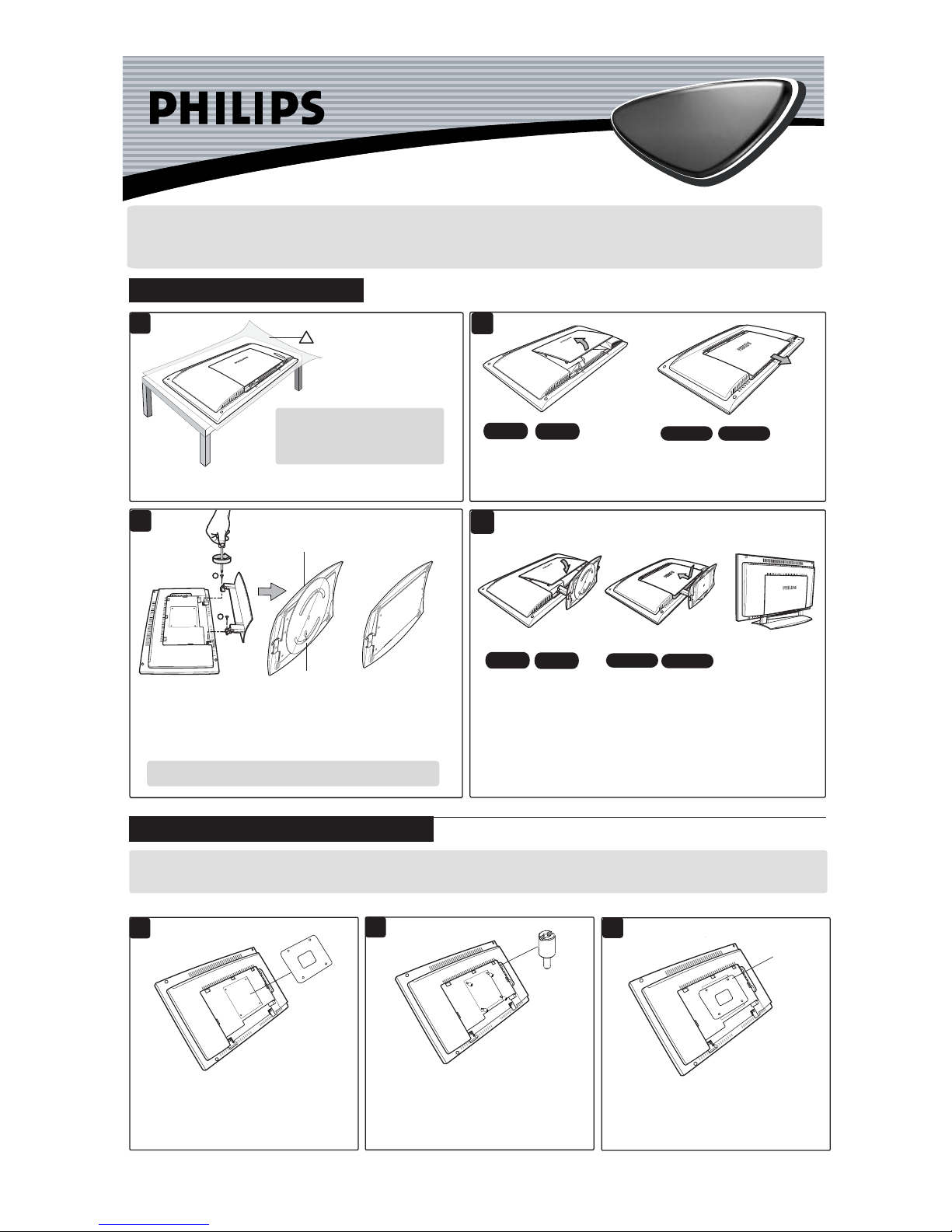
ASSEMBLING THE STAND
INSTALLING LCD TV ON THE WALL
For the 20"/23" models, open back
plate cover by gently pulling upwards.
For the 15"/17" models, open back
plate cover by sliding the plate cover
downwards and then pull upwards.
Bottom of swivel base
(20"/23" models only)
Check the stand arm
is rigid and properly
installed. Place the
set upright.
VESA
Bracket
does not
fit
If your VESA bracket does not fit into the slot at
the rear of the LCD TV, proceed to make use of
the four spacers provided. Note : If VESA bracket
fits into the slot, you need not use the spacers.
1
2
3
Spacer
x 4
Screw the four spacers to the holes at the rear of
the set. Ensure the spacers are properly tightened
(torque of 1.2N-m or 1 lbf-in).
Tighten
VESA
bracket
to spacers
23"/58cm
20"/51cm
17"/44cm
15"/39cm
For the 20"/23"models,
close back plate cover
by gently pushing
downwards.
For the 15"/17" models,
close back plate cover by
sliding plate upward.
Align arrow
to the center
1
For swivelling of the stand to function properly, adjust the swivel base at
the back of the stand until arrow is aligned in the center. Align the stand
studs into the holes at the bottom of the set. Put in the screws (provided)
into the 2 holes and tightened with a screwdriver.
CAUTION : While putting in the screws, hold onto the stand.
Place the set facing down on a protective
sheet close to the edge of a flat surface.
Ensure you have the following before
you assemble the stand :
– Two screws (supplied with set)
– One Screwdriver (not supplied)
4
NOTE : No swivel
base for 15"/17" models
Do the following when installing the LCD TV on the wall :
2
1
Ñ
Ñ
Ñ
!
Place the VESA bracket on the spacers and
tightened with the VESA bracket screws.
Quick Use and Hookup Guide
LCD TV
LCD TV
Power Button -
Press to turn the TV ON and OFF.
Status/Exit Button - Press to see the current channel number
on the TV screen. Also press to clear the TV menu after
control adjustments.
Sleep Button - Press to set the TV to automatically turn itself
OFF at a given amount of time.
VGA Mode Button - Press to directly enter PC mode.
Appicable to 15"/17"/23" models only.
TV Mode Button - Press to directly enter TV mode.
Auto Sound Button - Press to select an AutoSound™
control. Choose from three factory-set controls (VOICE, MUSIC,
and THEATRE) and a PERSONAL to tailor the TV sound to
enhance the particular type of program you are watching.
Menu Button - Press for the onscreen menu to appear.
Pressing the menu button after menu selections are made
will exit the menu from the TV screen.
Volume (+) or (–) Buttons - Press to adjust the TV
sound level.
Number Buttons - Press the number buttons for direct
access to the TV channels. For a 2-digit channel, enter
the 2nd digit before the dash disappears. For a 3-digit
channel, enter the first digit followed the next 2 digits.
CC Button - Press to select Closed Captioning options
within the menu.
Program List - Press to display a list of channel numbers.
Each channel will appear as a selectable menu item.
FM Radio Mode Button - Press to directly enter Radio mode.
HD Mode Button - Press to directly enter HD mode.
Auto Picture Button - Press to select an AutoPicture™
control. Choose from four factory-set controls (MOVIES,
SPORTS, WEAK SIGNAL and MULTI MEDIA) and a
PERSONAL control that you set according to your own
preferences through the onscreen PICTURE menu. The four
factory-set controls will tailor the TV picture so as to enhance
the particular type of program you are watching, or to improve
the picture of a program that has a weak signal.
Format Button - Press to toggle the different screen format
options.
A/CH Button - Press to toggle between the currently viewed
channel and the previously viewed channel.
Cursor Buttons (Left, Right, Up, Down) - Press these buttons
to highlight, select, and adjust items on the TV's onscreen menu.
Channel (+) or (–) Buttons - Press to access the next or
previous channel.
Surf Button - Press to select previously viewed channels.
You can place up to 10 channels in memory. Then by pressing
the SURF button you can quickly view the select channels.
Source Button -
Press to toggle between the different
A/V Input jack connections and the currently tuned
channel.
Mute Button - Press to turn the TV sound OFF . Press
again to return the sound to its previous level.
Presentation of the LCD Televison . . . . . . . . . . . 2
Remote Control Operation . . . . . . . . . . . . . . . . . 2
Hooking Up the Television
Remote Control Batteries . . . . . . . . . . . . . . . . . . . 3
Cable/Cable Box TV . . . . . . . . . . . . . . . . . . . . . . 3
Antenna TV . . . . . . . . . . . . . . . . . . . . . . . . . . . . . 3
C
ONTENTS
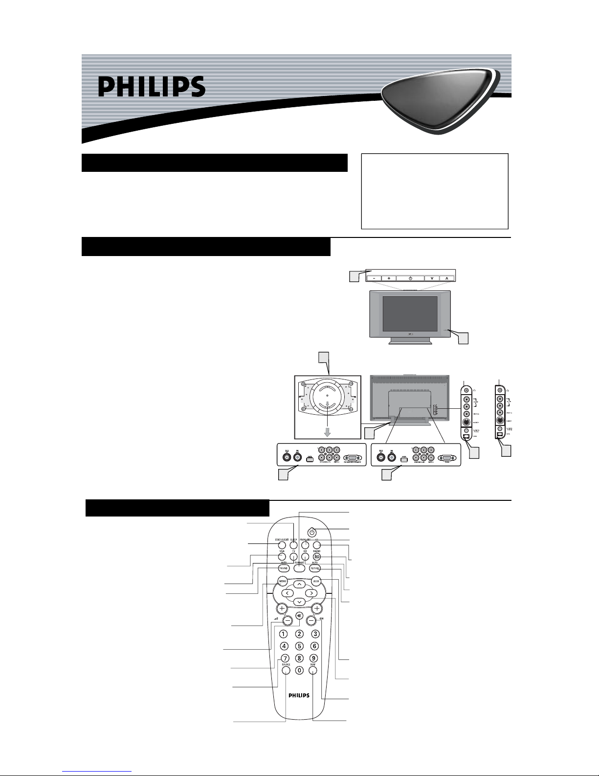
PRESENTATION OF THE LCD TELEVISION
Television keys
• 2 : to switch the TV on or off.
• VOLUME + / – : to adjust sound level.
• PROGRAM + /– : to select programmes.
To access or close menus, press the VOLUME + / –
keys simultaneously. The PROGRAM + / – keys can
be used to select an adjustment and the VOLUME + / –
keys make that adjustment.
Adjustable stand
The stand has swivel and tilt functions. For swivelling function,
ensure the arrows at the bottom of the stand arm and the
swivel base are aligned in the center (see diagram on the right).
For tilting function, you can tilt the set backward or forward to
your preferred angle.
Note : The stand can be removed and the LCD TV can be
installed on the wall. This set has four mounting interfaces fulfilling
VESA specifications. Pull out the back plate cover to access the four
installing interfaces. Installation of the LCD TV on the wall should
be carried out by qualified servicemen.Improper or incorrect
installation may render the set unsafe.
LED light and infrared sensors
Aim remote control at infrared sensors to activate TV controls.
Rear connectors
Located at the rear of the set.
Bottom connectors
Located at the bottom of the set.
2
5
2
1
3
PROGRAM
VOLUME
4
17"/20"/23"
models only
15" model
only
Bottom of
swivel base
5
20" model only
15"/17"/23" models only
REMOTE CONTROL OPERATION
4
1
2
3
4
5
AV1 Inputs . . . . . . . . . . . . . . . . . . . . . . . . . . . . . . 4
Component (CVI) Inputs. . . . . . . . . . . . . . . . . . . 4
HD (High Definition Inputs. . . . . . . . . . . . . . . . . 4
PC (Monotor) Inputs. . . . . . . . . . . . . . . . . . . . . . . 4
AV2 Inputs . . . . . . . . . . . . . . . . . . . . . . . . . . . . . . 4
Monitor Outputs . . . . . . . . . . . . . . . . . . . . . . . . . . 4
IMPORTANT
NOTE: This owner's manual is used with several
different television models. Not all features (and
drawings) discussed in this manual will necessarily
match those found with your television set. This is
normal and does not require that you contact your
dealer or request service.
WARNING: TO PREVENT FIRE OR SHOCK
HAZARD DO NOT EXPOSE THIS UNIT TO
RAIN OR EXCESSIVE MOISTURE.
2
 Loading...