

Page 1

CLASS NO.
Philips Innovation Services
3000 003 1359
1
2017-06-08
2
2017-06-29
WiFi HW reference Design 1.0
Approved
NAME
Wim van den Dungen
SUPERS
None
28
190 1 10 A4
DATA FMT
PDF
Tmpl v2.0
CHECK
DATE
2017-02-15
KONINKLIJKE PHILIPS N.V. 2017
3000 003 13562
FCC ID: 2AALC0031357
IC: 22799-0031357
HVIN:
3000 003
13592
Philips Innovation Services
PInS WiFi reference design
Datasheet PInS WiFi module Draft
PRELIMINARY
COMPONENT FOR PHILIPS PRODUCT USE ONLY
Page 2

Philips Innovation Services
Datasheet WiFi module
Doc Level:
QMS
Process:
04 Realisation
Approver:
Luc Tan
Version:
Status:
V1.0
Approved
Classification:
Confidential
Author:
Wim van den Dungen
Page: 2 of 28
Last modified:
2017 Jul 3
Printed copies are uncontrolled unless authenticated Printed copies are uncontrolled unless authenticated
TABLE OF CONTENT
COMPONENT FOR PHILIPS PRODUCT USE ONLY 1
DOCUMENT CHANGE HISTORY 4
1 INTRODUCTION 5
1.1 INTRODUCTION 5
1.2 OVERVIEW SPECIFICATIONS 6
1.3 FUNCTIONAL BLOCK DIAGRAM 7
1.4 OPEN POINTS 8
1.5 DEFINITIONS, ACRONYMS & ABBREVIATIONS 8
2 APPLICATIONS 9
3 INTERFACE 10
3.1 4 MAIN INTERFACES 10
4 ANTENNAS 11
4.1.1 APPROVED ANTENNA 11
5 OPERATION, STORAGE AND TRANSPORT CONDITIONS 11
5.1 OPERATIONAL CONDITIONS NORMAL OPERATION 11
5.2 OPERATIONAL CONDITIONS STORAGE 12
5.3 OPERATIONAL CONDITIONS TRANSPORT 12
5.4 ADDITIONAL CONDITIONAL SPECIFICATIONS 12
5.5 ENVIRONMENTAL 12
6 ARCHITECTURAL CHOICES AND CONSTRAINTS 13
6.1 STRATEGIC INTERFACES 13
6.2 STRATEGIC MODULE SIZE 13
7 GENERAL, SAFETY, LEGAL & SECURITY STANDARDS 14
7.1 GENERAL STANDARDS 14
7.2 CONTAMINATION 14
7.3 FCC, IC, SRRC, ETSI COMPLIANCE 14
4.1 EXTERNAL ANTENNA 11
7.3.1 IC COMPLIANCE 14
7.3.2 CONFORMITÉ AUX NORMES D’INDUSTRIE CANADA 14
7.3.3 FCC STATEMENT 15
7.4 INSTALLATION INSTRUCTION 15
7.5 LABEL REQUIREMENTS FOR END PRODUCT 16
7.6 UL COMPLIANCE 16
8 SPECIFICATIONS 16
8.1 MECHANICAL 16
8.2 ELECTRICAL 18
8.3 TYPICAL VALUES 18
8.4 COMMUNICATION 18
Page 3

Philips Innovation Services
Datasheet WiFi module
Doc Level:
QMS
Process:
04 Realisation
Approver:
Luc Tan
Version:
Status:
V1.0
Approved
Classification:
Confidential
Author:
Wim van den Dungen
Page: 3 of 28
Last modified:
2017 Jul 3
Printed copies are uncontrolled unless authenticated Printed copies are uncontrolled unless authenticated
8.5 ABSOLUTE MAXIMUM RATINGS 19
8.6 MODULE LEVEL RECOMMENDED MAXIMUM RATINGS 19
8.7 ELECTROSTATIC DISCHARGE SPECIFICATIONS 20
9 RF CHARACTERISTICS 21
10 RELIABILITY 22
11 REFLOW PROFILE 22
11.1 TYPICAL PROFILE 22
11.2 MEASURED REFLOW PROFILE DURING TEST RUNS 22
12 FOOTPRINT DETAILS 23
13 ORDERING INFORMATION 26
13.1 ORDERING VARIANT OF MODULE, PRODUCT SPECIFIC 26
13.2 COMMON PINS HW VARIANT, PCBA 12NC ORDERING INFORMATION 26
13.3 MODULE LABELING 27
14 REFERENCES 28
Page 4

Philips Innovation Services
Datasheet WiFi module
Doc Level:
QMS
Process:
04 Realisation
Approver:
Luc Tan
Version:
Status:
V1.0
Approved
Classification:
Confidential
Author:
Wim van den Dungen
Page: 4 of 28
Last modified:
2017 Jul 3
Printed copies are uncontrolled unless authenticated Printed copies are uncontrolled unless authenticated
Date
Person
Version
Reason
15-02-2017
Wim van den Dungen
0.1
First draft
29-03-2017
Wim van den Dungen
0.2
Cleanup and added details
31-03-2017
Wim van den Dungen
0.9
Proposed for release
03-04-2017
Wim van den Dungen
0.91
Added footprint information
14-04-2017
Wim van den Dungen
0.92
Minor updates MSL level, Footprint
14-04-2017
Wim van den Dungen
0.93
Minor updates, explaining MSL level and WoW
02-06-2017
Ioannis Pappous
0.94
Added information about standards compliance.
Update labeling, added external antenna
information. Layout schematics included. Added
missing information. Document reorganized
21-06-2017
Luc Tan
1.0
Release the document
Add country settings.
State that China regulation is under
development.
Update external antenna directivity.
Update FCC ID and IC ID.
Clarify the 12 variants
Use full 12NC not 11NC+x
Add HVIN:
DOCUMENT CHANGE HISTORY
Page 5
Philips Innovation Services
Datasheet WiFi module
Doc Level:
QMS
Process:
04 Realisation
Approver:
Luc Tan
Version:
Status:
V1.0
Approved
Classification:
Confidential
Author:
Wim van den Dungen
Page: 5 of 28
Last modified:
2017 Jul 3
Printed copies are uncontrolled unless authenticated Printed copies are uncontrolled unless authenticated
1 Introduction
1.1 Introduction
PInS WiFi module V1.0 is a PCB Wi-Fi module designed by Philips innovation services (PInS) and based
on the latest Cypress WiFI SoC. The design is based on an internal Philips study and is backwards
compatible with an already used Philips module called Philips YD (obsolete), Additional functionality is
added to optimize usability and a cost effective solution of adding connectivity to Philips products.
The design is aligned with Philips CDPP, PSSO, PInS, and multiple business and making fast and easy
integration possible.
See datasheet of CYW43903 WICED™™ IEEE 802.11 a/b/g/n SoC with an Embedded Applications
Processor [1] for detailed specifications.
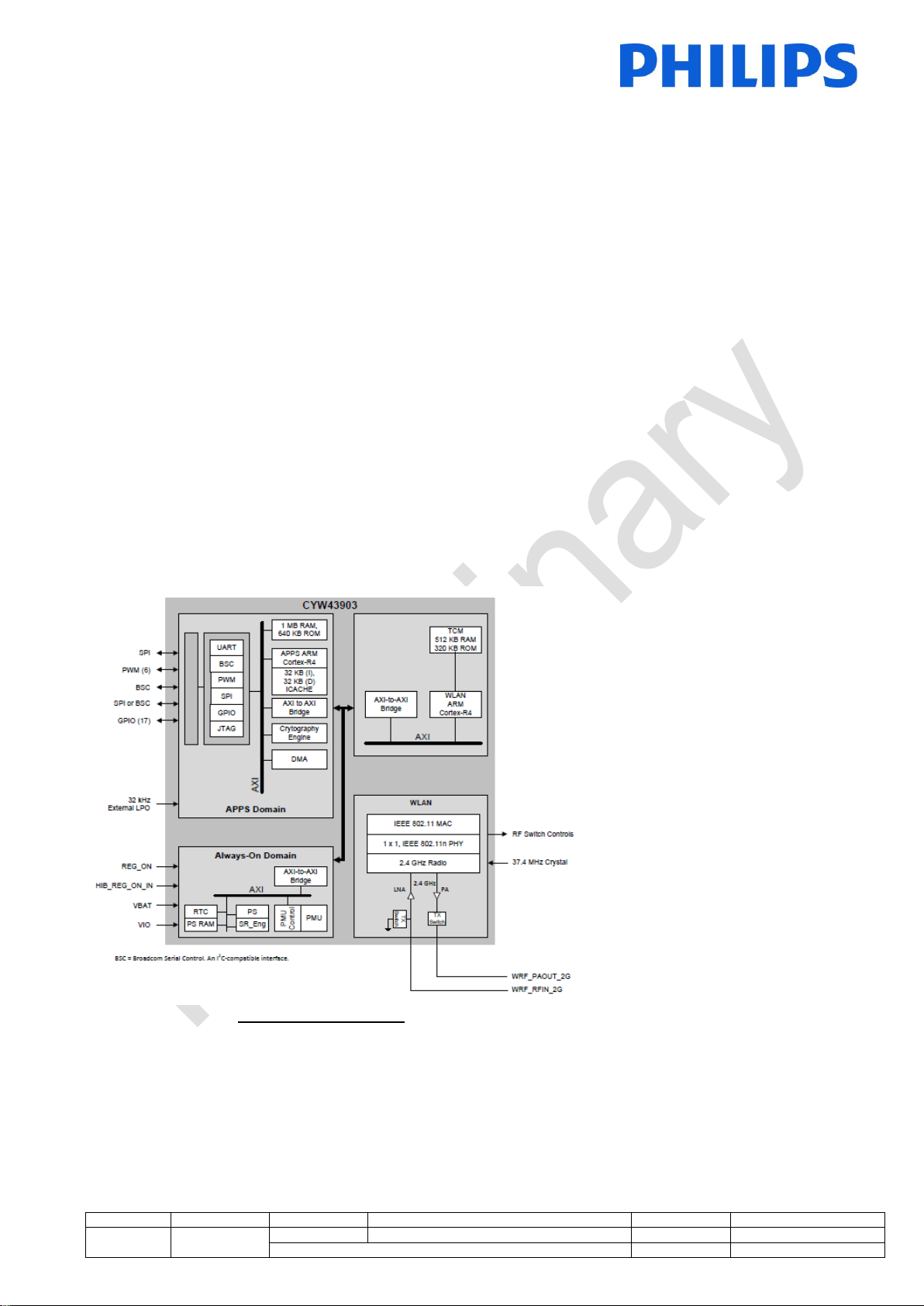
General description of the CYW43903 SoC that forms the bases of the module reference design:
The Cypress CYW43903 embedded wireless system-on-a-chip (SoC) is uniquely suited for Internet-ofThings applications. It is IEEE 802.11n compliant and provides full IEEE 802.11 b/g legacy compatibility with
enhanced performance. The device includes an ARM Cortex-based applications processor, a single stream
IEEE 802.11n MAC/baseband/radio, a power amplifier (PA), and a receive low-noise amplifier (LNA). It also
supports optional antenna diversity for improved RF performance in difficult environments. The CYW43903 is
an optimized SoC targeting embedded Internet-of-Things applications in the industrial and medical sensor,
home appliance markets. Using advanced design techniques and process technology to reduce active and
idle power, the device is designed for embedded applications that require minimal power consumption and a
compact size. The device includes a PMU for simplifying system power topology and allows for direct
operation from a battery while maximizing battery life.
Figure 1: Block Diagram
Page 6

Philips Innovation Services
Datasheet WiFi module
Doc Level:
QMS
Process:
04 Realisation
Approver:
Luc Tan
Version:
Status:
V1.0
Approved
Classification:
Confidential
Author:
Wim van den Dungen
Page: 6 of 28
Last modified:
2017 Jul 3
Printed copies are uncontrolled unless authenticated Printed copies are uncontrolled unless authenticated
• Dual ARM clocked at 160 MHz
• 1 MB of SRAM and 640 KB ROM available for the
applications processor.
• 64Mb encrypted flash storage
• IEEE 802.11 b/g/n 1×1 2.4 GHz radio.
• Single- and dual-antenna support. PCB and
external including diversity.
The module supports the following standards:
• IEEE 802.11n
• IEEE 802.11b
• IEEE 802.11g
• IEEE 802.11d
• IEEE 802.11h
• IEEE 802.11i
• Security:
– WEP
– WPA Personal
– WPA2 Personal
– WMM
– WMM-PS (U-APSD)
– WMM-SA
– AES (hardware accelerator)
– TKIP (hardware accelerator)
– CKIP (software support)
Proprietary Protocols:
– CCXv2
– CCXv3
– CCXv4
– CCXv5
– WFAEC
The module supports the following additional
standards:
• IEEE 802.11r—Fast Roaming (between APs)
• IEEE 802.11w—Secure Management Frames
• IEEE 802.11 Extensions:
– IEEE 802.11e QoS enhancements (already
supported as per the WMM specification)
– IEEE 802.11i MAC enhancements
– IEEE 802.11k radio resource measurement
Supported countries:
- Europe (ETSI)
- United states
- Canada
- China (TBC)
1.2 Overview specifications
Page 7
Philips Innovation Services
Datasheet WiFi module
Doc Level:
QMS
Process:
04 Realisation
Approver:
Luc Tan
Version:
Status:
V1.0
Approved
Classification:
Confidential
Author:
Wim van den Dungen
Page: 7 of 28
Last modified:
2017 Jul 3
Printed copies are uncontrolled unless authenticated Printed copies are uncontrolled unless authenticated
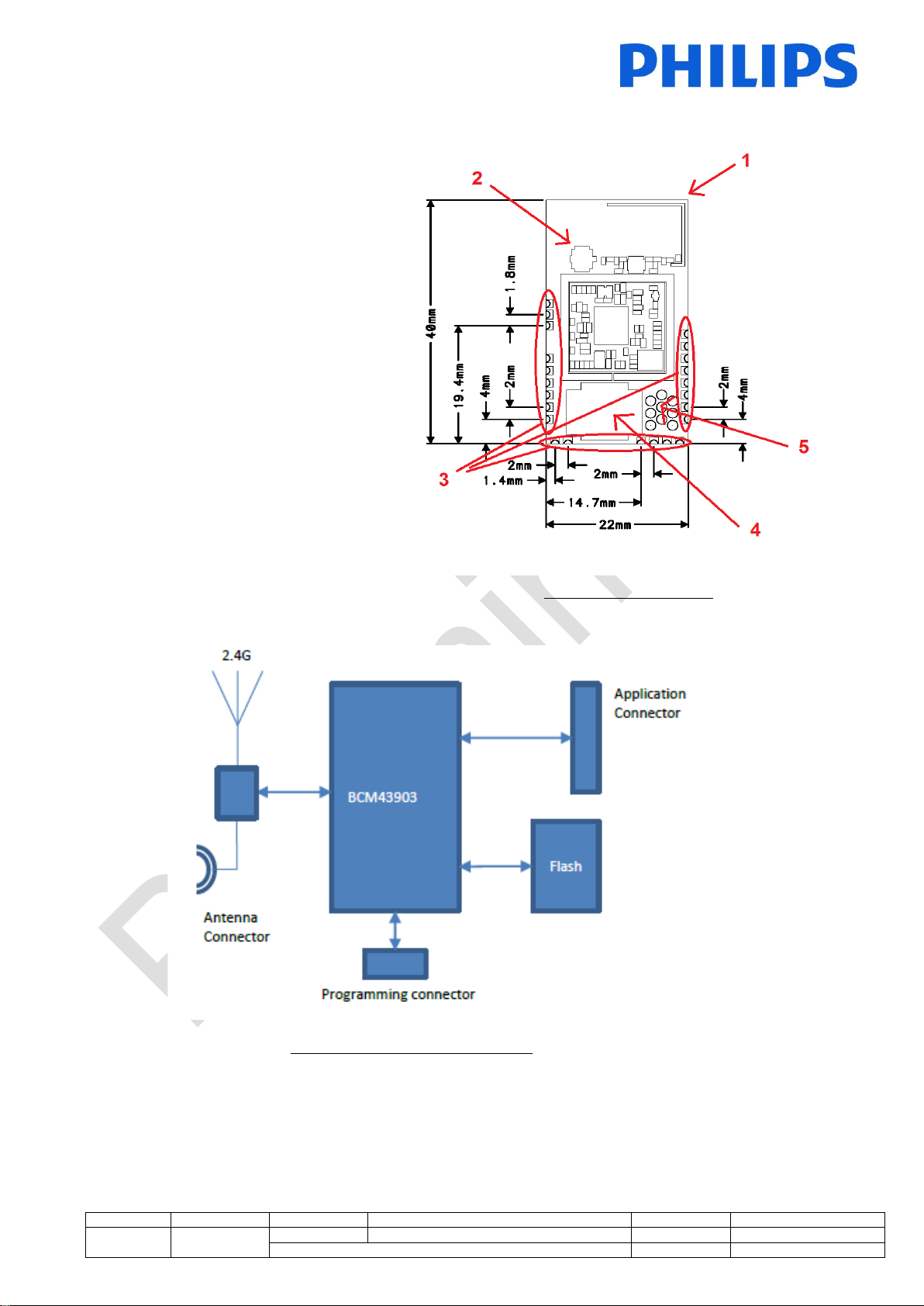
• External Flash 8MB
• (1) PCB Trace antenna
• (2) Connector for external
antenna
• Antenna diversity
• (3) Castellation SMT solder
mounting
• (4) 10 pin wire connector
• 16 I/O (14 shared)
• I2C
• SPI
• Main UART
• Debug UART
• JTAG
• 3V3 supply voltage
• (5) High speed production
programming
• RF Shield
• FCC, ETSI, IC module certified
• SRCC TBC
• Wi- Fi Alliance certified
• 40mm * 22mm * 9mm
Figure 2: Module Design
1.3 Functional block diagram
Figure 3: Functional block diagram
Page 8

Philips Innovation Services
Datasheet WiFi module
Doc Level:
QMS
Process:
04 Realisation
Approver:
Luc Tan
Version:
Status:
V1.0
Approved
Classification:
Confidential
Author:
Wim van den Dungen
Page: 8 of 28
Last modified:
2017 Jul 3
Printed copies are uncontrolled unless authenticated Printed copies are uncontrolled unless authenticated
PInS
Philips Innovation Services
CDPP
Philips Connected Digital Platforms & Propositions
Wi-Fi
Wireless Fidelity
RF
Radio Frequency
IEEE
Institute of Electrical and Electronics Engineers
PCB
Printed Circuit Board
PCBA
Printed Circuit Board Assembly
MAC
Media Access Control
AP
Access Point
ARM
Semiconductor IP company
SMT
Surface Mount Technology
ESD
Electrostatic Discharge
EU
European Union
USA
United States of America
FCC
Federal Communications Commission
SRRC
State Radio Regulation of China
RSS
Radio Standards Specifications
ETSI
European Telecommunications Standard Institute
ISTA
International Safe Transit Association
PMU
Power Management Unit
IEC
International Electrotechnical Commission
MCU
Micro-Controller Units
MSL
Moisture Sensitive Level
CE
Conformity European
UL
Underwriters Laboratories (safety organization)
TLL
Transistor-Transistor Logic
UART
Universal Asynchronous Receiver/ Transmitter
I2C
Inter-Integrated Circuit
SPI
Serial Peripheral Interface
JTAG
Joint Test Action Group (electronics industry association)
I/O
Input/ Output
RX
Receiver
FW
FirmWare
HW
HardWare
SoC
System on Chip
AWG
American Wire Gauge
PVC
Polyvinylchloride
DSSS
Direct-Sequence Spread Spectrum
OFDM
Orthogonal Frequency Division Multiplexing
PSDU
Physical layer Service Data Unit
MCS
Modulation and Coding Scheme
LNA
Low-Noise Amplifier
PER
Packet Error Rate
STBC
Space-Time Block Codes
GI
Guard Interval
BLE
Bluetooth Low Energy
EMC
Electromagnetic Compatibility
ESF
European Safety Federation
WEP
Wired Equivalent Privacy
WPA
Wi-Fi Protected Access
AES
Advanced Encryption Standard
TKIP
Temporal Key Integrity Protocol
1.4 Open Points
Adding details on request of Philips Business units and manufacturer.
1.5 Definitions, Acronyms & Abbreviations
Page 9

Philips Innovation Services
Datasheet WiFi module
Doc Level:
QMS
Process:
04 Realisation
Approver:
Luc Tan
Version:
Status:
V1.0
Approved
Classification:
Confidential
Author:
Wim van den Dungen
Page: 9 of 28
Last modified:
2017 Jul 3
Printed copies are uncontrolled unless authenticated Printed copies are uncontrolled unless authenticated
CKIP
Cisco Key Integrity Protocol
WMM
Wi-Fi Multimedia
SRAM
Static Random-Access Memory
ROM
Read-Only Memory
TBC
To Be Confirmed
HVIN
Hardware Version Identification Number
2 Applications
The PInS Wi-Fi reference design / platform is intended to be used inside Philips to enable connected
propositions and maximize the re-use with Philips and CDPP connectivity platforms. The application
supported are all Philips products including medical class products. The module is designed to be nonblocking for medical product integration (all tests and documentation are available). The module itself is not a
medical device as such.
Page 10

Philips Innovation Services
Datasheet WiFi module
Doc Level:
QMS
Process:
04 Realisation
Approver:
Luc Tan
Version:
Status:
V1.0
Approved
Classification:
Confidential
Author:
Wim van den Dungen
Page: 10 of 28
Last modified:
2017 Jul 3
Printed copies are uncontrolled unless authenticated Printed copies are uncontrolled unless authenticated
Figure 4: Interface functions
3 Interface
The interfaces of the module are defined as below. The interfaces are considered part of the platform in
order to have a common base, to maximize re-use and to provide backward compatibility and future
extensions of the platform.
3.1 4 main interfaces
There are 4 main interface sections in the module design (see Figure 2):
- (3) Castellations. Main interface for SMT placement of the module on product specific PCB board
holding communication, programming, supply and test interfaces. (X101..X124)
- (4) 10 pin AWG24 Board to Wire connector (JST SM10B-ZPDSS-TF(LF)(SN)): Main interface for
product integration based on Wired connection. This connector having Supply, Main UART, SPI, I2C
and I/O. (X125)
- (2) RF external connector (Hirose U.FL-R-SMT-1(10)), interface to support external antenna and
antenna diversity. (X2)
- (5) Fast programming pads: The fast programming pads are intended for in production high speed
programming and testing. (I1…I9)
Page 11

Philips Innovation Services
Datasheet WiFi module
Doc Level:
QMS
Process:
04 Realisation
Approver:
Luc Tan
Version:
Status:
V1.0
Approved
Classification:
Confidential
Author:
Wim van den Dungen
Page: 11 of 28
Last modified:
2017 Jul 3
Printed copies are uncontrolled unless authenticated Printed copies are uncontrolled unless authenticated
TE
Manufacturer
TE connectivity
Part Number
2118309-2
Polarization
Linear
Gain
2.5 dBi (2.4GHz band)
Impedance
50 Ω
Size
40.0 x 8.0 x 1.0 mm
Connector
u.fl
Approval
FCC, IC and ETSI (SRCC TBC)
Description
Range
Temperature range
-20°C...+70°C
Atmospheric pressure range
60kPa...110kPa
Relative humidity range
5%...95%
4 Antennas
The design includes 3 antenna options, PCB trace antenna, external antenna and antenna diversity.
The PCB trace antenna is design to have a performance of > 30% efficiency and maximum gain of 3dBi.
4.1 External Antenna
This chapter gives an overview of the external antenna that can be fitted to the WiFi module.
This radio transmitter IC has been approved by Industry Canada to operate with the antenna
type listed below with the maximum permissible gain and required antenna impedance for each
antenna type indicated. Antenna types not included in this list, having a gain greater than the
maximum gain indicated for that type, are strictly prohibited for use with this device.
Le chapitre suivant donne un aperçu de l'antenne externe qui peut être installée sur le module
WiFi. Cet émetteur radio IC été approuvé par Industry Canada pour fonctionner avec
le type d’antenne énumérés ci-dessous avec le gain maximum autorisé et l’impédance
nécessaire pour chaque type d’antenne indiqué. Les types d’antenne ne figurant pas dans cette
liste et ayant un gain supérieur au gain maximum indiqué pour ce type-là sont strictement
interdits d’utilisation avec cet appareil.
For each antenna, the "Approvals" field defines in which test reports the antenna is included. Definitions
of the «Approvals» field are:
FCC - The antenna is included in the FCC test reports and thus approved for use in
countries that accept the FCC radio approvals, primarily US.
IC - The antenna is included in the IC (Industry Canada) test reports and thus approved for
use in countries that accept the IC radio approvals, primarily Canada.
ETSI - The antenna is included in the ETSI test reports and thus approved for use in
countries that accept the ETSI radio approvals (EU).
SRRC – TBC.
4.1.1 Approved antenna
5 Operation, storage and transport conditions
5.1 Operational conditions normal operation
Page 12

Philips Innovation Services
Datasheet WiFi module
Doc Level:
QMS
Process:
04 Realisation
Approver:
Luc Tan
Version:
Status:
V1.0
Approved
Classification:
Confidential
Author:
Wim van den Dungen
Page: 12 of 28
Last modified:
2017 Jul 3
Printed copies are uncontrolled unless authenticated Printed copies are uncontrolled unless authenticated
Description
Range
Temperature range
5°C...+50°C
Atmospheric pressure
range
60 ... 110 kPa
Relative humidity range
10 ... 95 % rH
non-condensing
Tested for time in storage
6 months.
Devices are stored in a
vacuum sealed barrier bag
and stored in a reel to
support SMT pick and
place mounting
MSL3
Description
Range
Temperature range
-30 ... 70 °C
Atmospheric pressure
range
60 ... 120 kPa
Relative humidity range
10 ... 95 % rH
non-condensing
Conform broadband
random vibrations
according to IEC 60068-264
Severity level IEC 60721-47, Class- 7M2
And in line with ISTA
standard
conform the shock test IEC
60068-2-27 mounting
Severity level IEC 60724-47 Class-7M3
And in line with ISTA
standard
The device packaging
complies with ISTA
standard 2A
ISTA standard 2A
5.2 Operational conditions storage
5.3 Operational conditions Transport
5.4 Additional conditional specifications
- Module is MSL 3 level, transport and storage in sealed packaging,
(limit open air “life out of the bag” to <168 hours: make use of sealed vacuum bag which will limit
exposure of the chip to moisture to less than 168 hours prior to the last reflow round (MSL3= 168
hours). in case the chips were exposed for more than 168 hours, IPC/JEDEC J-STD-020B defines a
“baking” process to get the parts fit for use again. (min 8 hours @125°C))
- Packaging supports SMT (Pick and Place) tape and reel.
- Module should be handle as component, handle with care, and ESD protection should be used.
- Supply should be within specifications and clean, injected noise can be amplified and cause the
module to fail and work out of specification.
- All modules are functional tested, Wi-Fi connection speed, Carrier Wave tests, I/O tests and UART
tests. The Wired interface connector is not tested, needs to be tested at product level when used.
- Maximum reflow processes allowed is 1. (Critical Murata 2.4 GHz filter).
5.5 Environmental
- Module complies to Philips Regulated Substances List PHGR-GS-BP01-012.
- CE compliance
Page 13

Philips Innovation Services
Datasheet WiFi module
Doc Level:
QMS
Process:
04 Realisation
Approver:
Luc Tan
Version:
Status:
V1.0
Approved
Classification:
Confidential
Author:
Wim van den Dungen
Page: 13 of 28
Last modified:
2017 Jul 3
Printed copies are uncontrolled unless authenticated Printed copies are uncontrolled unless authenticated
Image 1: Connector
6 Architectural Choices and Constraints
The PInS Wi-Fi reference design is based on an internal Philips study on common requirements and product
examples. Out of this study the below strategic interfaces, shape and dimensions are defined.
Strategic interfaces, shape and dimensions of the reference design are beneficial to leverage scale,
compatibility and future updates and extensions. Wi-Fi and BLE chip updates, combo solutions and other IoT
technologies are on the roadmap and planned to be compatible.
6.1 Strategic interfaces
1- PCB Trace antenna (Omnidirectional and optimized for easy integration, > 30% efficiency)
2- Connector for external antenna option (In combination with RF switch optional) (Diversity option)
3- Castellation’s, SMT solder mounting option, See specific interface functions in figure 4.
4- Connector (AWG 24 compatible wires connector), strategic, Main MCU interface, Supply, SPI, I2C and I/O
(see figure 2).
5- Direct High Speed Flash programming, production.
6.2 Strategic module size
Model strategic size is 40mm (+/- 0.25mm) * 22mm (+/- 0.25mm) * 9mm
The module can be mounted into a slotted sliding fixture. Mechanical castellations are added for locking in
place. See detailed mechanical drawings in chapter 8.1 for more information.
Page 14

Philips Innovation Services
Datasheet WiFi module
Doc Level:
QMS
Process:
04 Realisation
Approver:
Luc Tan
Version:
Status:
V1.0
Approved
Classification:
Confidential
Author:
Wim van den Dungen
Page: 14 of 28
Last modified:
2017 Jul 3
Printed copies are uncontrolled unless authenticated Printed copies are uncontrolled unless authenticated
Country/setting
XX/17
NL/1
US
Applicable
Not Applicable
Canada
Applicable
Not Applicable
Europe
Applicable
Applicable
China
TBC
TBC
7 General, Safety, Legal & Security Standards
See Philips Safety, Legal and security standards used, see specific documents available on request. Fully
compliant with Product and Services Security Office (PSSO) and fully compliant to Philips requirements.
On request detailed documentation can be provided on Production, Approbation and certification. For
specific requirements and tractability.
Contact PInS for re-use module level certification and referrals
7.1 General Standards
The PInS WiFi module complies to the Safety Standard EN 62368-1 and is manufactured following the
ROHS/REACH directives.
7.2 Contamination
The module is validated as Pollution degree 2 equipment, normally only nonconductive pollution occurs.
Temporary conductivity caused by condensation is to be expected.
7.3 FCC, IC, SRRC, ETSI Compliance
The following modes of operation is supported by the module with
WLAN Firmware : wl0: Dec 19 2016 19:29:37 version 7.15.168.78 (r663126) FWID 01-8ba7c839
The system is designed to comply with the standards as mentioned below as part of a complete assembly.
The unit is classified as a class B product.
The PInS WiFi module is IC and FCC certified for the radio aspects (in the USA and Canada) and complies
with radio tests ETSI EN 300 328 V2.1.1 for EU. In addition, the module is complies with the EMC standards
for USA (FCC 15.209), EU (ETSI EN 301 489-17) and Canada. The certification of China is to be confirmed.
7.3.1 IC compliance
This device complies with Industry Canada license-exempt RSS standard(s).
Operation is subject to the following two conditions:
1. This device may not cause interference, and
2. This device must accept any interference, including interference that may cause undesired operation
Under Industry Canada regulations, this radio transmitter may only operate using an antenna of a type and
of the device.
maximum (or lesser) gain approved for the transmitter by Industry Canada. To reduce potential radio
interference to other users, the antenna type and its gain should be chosen in such a way that the equivalent
isotropically radiated power (e.i.r.p.) is not more than that is necessary for successful communication.
This equipment complies with IC RSS-102 radiation exposure limits set forth for an uncontrolled
environment.
7.3.2 Conformité aux normes d’Industrie Canada
Cet appareil est conforme à la(aux) norme(s) RSS sans licence d’Industry Canada.
Son utilisation est soumise aux deux conditions suivantes :
1. Cet appareil ne doit pas causer d’interférences et
2. il doit accepter toutes interférences reçues, y compris celles susceptibles d’avoir des effets
indésirables sur son fonctionnement.
Page 15

Philips Innovation Services
Datasheet WiFi module
Doc Level:
QMS
Process:
04 Realisation
Approver:
Luc Tan
Version:
Status:
V1.0
Approved
Classification:
Confidential
Author:
Wim van den Dungen
Page: 15 of 28
Last modified:
2017 Jul 3
Printed copies are uncontrolled unless authenticated Printed copies are uncontrolled unless authenticated
Conformément aux réglementations d’Industry Canada, cet émetteur radio ne peut fonctionner qu’à l’aide
d’une antenne dont le type et le gain maximal (ou minimal) ont été approuvés pour cet émetteur par Industry
Canada. Pour réduire le risque d’interférences avec d’autres utilisateurs, il faut choisir le type d’antenne et
son gain de telle sorte que la puissance isotrope rayonnée équivalente (p.i.r.e) ne soit pas supérieure à celle
requise pour obtenir une communication satisfaisante. Cet équipement respecte les limites d’exposition aux
rayonnements IC CNR-102 définies pour un environnement non contrôlé.
7.3.3 FCC statement
This device complies with Part 15 of the FCC Rules. Operation is subject to the following two conditions:
1. This device may not cause harmful interference, and
2. This device must accept any interference received, including interference that may cause undesired
operation.
This equipment has been tested and found to comply with the limits for a Class B digital device, pursuant to
Part 15 of the FCC Rules. These limits are designed to provide reasonable protection against harmful
interference in a residential installation. This equipment generates, uses and can radiate radio frequency
energy and, if not installed and used in accordance with the instructions, may cause harmful interference to
radio communications. However, there is no guarantee that the interference will not occur in a particular
installation. If this equipment does cause harmful interference to radio or television reception, which can be
determined by turning the equipment off and on, the user is encouraged to try to correct the interference by
one or more of the following measures:
Reorient or relocate the receiving antenna
Increase the separation between the equipment and receiver
Connect the equipment into an outlet on a circuit different from that to which the receiver is
connected.
The PInS WiFi module is for OEM integrations only. The end-user product will be professionally installed in
such a manner that only the authorized antennas are used.
7.4 Installation instruction
Changes or modifications made to the module not expressly approved by Philips Innovation Services may
void the FCC / IC authorization to operate this equipment.
The use of the transceiver module is authorized in mobile or fixed host devices taking into account the
conditions listed below:
Philips Business Units (integrator) must ensure that the end user manual may not contain any
information about the way to install or remove the module from the final product.
Depending on the final host device additional authorization requirements for the non-transmitter
functions of the transmitter module may be required (i.e., Verification, or Declaration of Conformity)
Philips Business Units (integrator) are responsible for ensuring that after the module is installed and
operational the host continues to be compliant with the Part 15B unintentional radiator requirements.
The information on the label and in the user manual is required to be incorporated in the user
manual of the final host. see 47 CFR15 requirements for more details (e.g. 15.19 / 15.21 / 15.101 /
15.105 / RSS-GEN / ICES)
The module must be installed and used in strict accordance with Philips Innovation Services
instructions as described in the user documentation that comes with the module.
The end user manual for the final host product operating with this transmitter must include operating
instructions to satisfy RF exposure compliance requirements.
Page 16

Philips Innovation Services
Datasheet WiFi module
Doc Level:
QMS
Process:
04 Realisation
Approver:
Luc Tan
Version:
Status:
V1.0
Approved
Classification:
Confidential
Author:
Wim van den Dungen
Page: 16 of 28
Last modified:
2017 Jul 3
Printed copies are uncontrolled unless authenticated Printed copies are uncontrolled unless authenticated
This device contains
FCC ID: 2AALC0031357
IC ID: 22799-0031357
CMIIT ID: TBC
e.g
Radiofrequency radiation exposure Information:
This equipment complies with FCC radiation exposure limits set forth for an uncontrolled
environment. This equipment should be installed and operated with minimum distance of 20
cm between the radiator and your body.
This transmitter must not be co-located or operating in conjunction with any other antenna or
transmitter.
Cet équipement est conforme aux limites d'exposition aux rayonnements IC établies pour un
environnement non contrôlé. Cet équipement doit être installé et utilisé avec un minimum de
20 cm de distance entre la source de rayonnement et votre corps.
The antenna of the module may not be removed, replaced nor modified. The
antenna must not be co-located or operating in conjunction with any other antenna
or transmitter. No additional antenna must be used.
When the final host product operating with this transmitter deviate from above,
installation of this module into specific final hosts may require the submission of a
Class II permissive change application containing data pertinent to RF Exposure,
spurious emissions, ERP/EIRP, and host/module authentication, or new application
if appropriate.
7.5 Label requirements for end product
For an end product using the PInS WiFI module there must be a label containing, at least, the following
information:
The label must be affixed on an exterior surface of the end product such that it will be visible upon inspection
in compliance with the modular approval guidelines developed by the FCC.
In accordance with 47 CFR § 15.19, the end product shall bear the following statement in a conspicuous
location on the device:
"This device complies with Part 15 of the FCC Rules.
Operation is subject to the following two conditions;
(1) This device may not cause harmful interference, and
(2) This device must accept any interference received, including interference that may cause undesired
operation."
7.6 UL compliance
UL94V-0 compliance on PCB level.
8 Specifications
8.1 Mechanical
The dimensions and footprint are part of the platform and are considered strategic to have a common base.
Supporting backwards compatibility and future extensions of the platform proposition.
The main dimensions are 40mm * 22mm (+/- 0.250mm) and a maximum height of <9mm.
Refer to the latest sheet 110 [3] of the PCB for more information about the mechanical drawings.
Page 17

Philips Innovation Services
Datasheet WiFi module
Doc Level:
QMS
Process:
04 Realisation
Approver:
Luc Tan
Version:
Status:
V1.0
Approved
Classification:
Confidential
Author:
Wim van den Dungen
Page: 17 of 28
Last modified:
2017 Jul 3
Printed copies are uncontrolled unless authenticated Printed copies are uncontrolled unless authenticated
Figure 9: Mechanical drawing
Page 18

Philips Innovation Services
Datasheet WiFi module
Doc Level:
QMS
Process:
04 Realisation
Approver:
Luc Tan
Version:
Status:
V1.0
Approved
Classification:
Confidential
Author:
Wim van den Dungen
Page: 18 of 28
Last modified:
2017 Jul 3
Printed copies are uncontrolled unless authenticated Printed copies are uncontrolled unless authenticated
Description
Value
Supply voltage
3.3V
I/O input high voltage
3.3V
I/O input low voltage i
0V
I/O output high voltage
equal or larger than
2.4V
I/O output low voltage
equal or less than
0.4V
Supply voltage
Vpp <5mV recommended,
use correct decoupling and
filters if needed
Description
Typical
Main product UART
interface that operates at
3V3 TTL levels.
115200
Debug UART interface that
operates at 3V3 TTL levels
115200
SPI 4-wire master interface
bit-bang driver
1Mbps
SPI 4-wire master interface
hardware driver
20Mbps
I2C master interface
operating at a frequency
100kHz and 400kHz
JTAG interface
8.2 Electrical
General electrical specifications as tested on module level, for detailed specifications see datasheet of
CYW43903 WICED™™ IEEE 802.11 a/b/g/n SoC with an Embedded Applications Processor.
8.3 Typical Values
8.4 Communication
Page 19

Philips Innovation Services
Datasheet WiFi module
Doc Level:
QMS
Process:
04 Realisation
Approver:
Luc Tan
Version:
Status:
V1.0
Approved
Classification:
Confidential
Author:
Wim van den Dungen
Page: 19 of 28
Last modified:
2017 Jul 3
Printed copies are uncontrolled unless authenticated Printed copies are uncontrolled unless authenticated
Parameter
Symbol
Value
Unit
3.3V DC supply voltage
VDD_3P3
-0.5 to 3.9
V
Maximum undershoot voltage for I/O
V
undershoot
-0.5
V
Maximum overshoot voltage for I/O
V
overshoot
VDD_3P3 + 0.5
V
Maximum junction temperature
TJ
-0.5 to 3.9
°C
Description
Range
Supply voltage in the range
3.13V…3.6V
I/O input high voltage in the range
2.0 V…3.8V
I/O input low voltage in the range
-0.5V…0.8V
I/O output high voltage equal or larger than
2.4V
I/O output low voltage equal or less than
0.4V
Supply voltage
Vpp <5mV recommended, use correct decoupling
and filters if needed
8.5 Absolute Maximum Ratings
Caution! The absolute maximum ratings indicate levels where permanent damage to the device can occur,
even if these limits are exceeded for only a brief duration. Functional operation is not guaranteed under
these conditions. Operation at absolute maximum conditions for extended periods can adversely affect longterm reliability of the device. Information out of CYW43903 datasheet core SoC.
8.6 Module level recommended Maximum ratings
Page 20

Philips Innovation Services
Datasheet WiFi module
Doc Level:
QMS
Process:
04 Realisation
Approver:
Luc Tan
Version:
Status:
V1.0
Approved
Classification:
Confidential
Author:
Wim van den Dungen
Page: 20 of 28
Last modified:
2017 Jul 3
Printed copies are uncontrolled unless authenticated Printed copies are uncontrolled unless authenticated
8.7 Electrostatic Discharge Specifications
Extreme caution must be exercised to prevent electrostatic discharge (ESD) damage. Proper use of wrist
and heel grounding straps to discharge static electricity is required when handling these devices. Always
store unused material in its antistatic packaging. ESD specifications are based directly on the core
components specifications. No additional protection added on module level.
ESD specifications
Page 21

Philips Innovation Services
Datasheet WiFi module
Doc Level:
QMS
Process:
04 Realisation
Approver:
Luc Tan
Version:
Status:
V1.0
Approved
Classification:
Confidential
Author:
Wim van den Dungen
Page: 21 of 28
Last modified:
2017 Jul 3
Printed copies are uncontrolled unless authenticated Printed copies are uncontrolled unless authenticated
Description
Range
Closed-loop TX power variation at highest power
level stetting.
Across full temperature and voltage range.
Applies to 10dBm to 20dB output power range
Max +/- 1.5dB
See [1] for actual value
9 RF characteristics
Also see datasheet of CYW43903 WICED™™ IEEE 802.11 a/b/g/n SoC with an Embedded Applications
Processor.
See datasheet CYW43903 WICED™ IEEE 802.11 a/b/g/n SoC with an Embedded Applications Processor
[1] for additional information.
Page 22

Philips Innovation Services
Datasheet WiFi module
Doc Level:
QMS
Process:
04 Realisation
Approver:
Luc Tan
Version:
Status:
V1.0
Approved
Classification:
Confidential
Author:
Wim van den Dungen
Page: 22 of 28
Last modified:
2017 Jul 3
Printed copies are uncontrolled unless authenticated Printed copies are uncontrolled unless authenticated
10 Reliability
Lifetime target of 7 years,
Field failure rate target equal to or less than 0.5%
Target warranty period of 2 years
11 Reflow profile
11.1 Typical profile
Figure 11: Reflow profile
11.2 Measured reflow profile during test runs
Figure 12: Reflow profile during test runs
Page 23

Philips Innovation Services
Datasheet WiFi module
Doc Level:
QMS
Process:
04 Realisation
Approver:
Luc Tan
Version:
Status:
V1.0
Approved
Classification:
Confidential
Author:
Wim van den Dungen
Page: 23 of 28
Last modified:
2017 Jul 3
Printed copies are uncontrolled unless authenticated Printed copies are uncontrolled unless authenticated
12 Footprint details
TOP view
Handle it as a module, black box to solder it on a PCB
Module length 40 mm
Module width 22 mm
Module PCB thickness = 0.8±0.1 mm
Module max height 10 mm (connector)
Solder method is reflow
Number of SMD pins are 23.
Pad – edge shape from the module are castellation shapes.
Use Partly metallized mounting base terminal
Implement PCB edge indication = top of metal screening box (28 mm from the bottom)
Place route keep out under the component (no via’s and prevent interference)
There are 2 position non plated 1.3 mm castellation shapes at the side, needed for its own PCB
assembly.
Page 24

Philips Innovation Services
Datasheet WiFi module
Doc Level:
QMS
Process:
04 Realisation
Approver:
Luc Tan
Version:
Status:
V1.0
Approved
Classification:
Confidential
Author:
Wim van den Dungen
Page: 24 of 28
Last modified:
2017 Jul 3
Printed copies are uncontrolled unless authenticated Printed copies are uncontrolled unless authenticated
Figure 13: Layout
Page 25

Philips Innovation Services
Datasheet WiFi module
Doc Level:
QMS
Process:
04 Realisation
Approver:
Luc Tan
Version:
Status:
V1.0
Approved
Classification:
Confidential
Author:
Wim van den Dungen
Page: 25 of 28
Last modified:
2017 Jul 3
Printed copies are uncontrolled unless authenticated Printed copies are uncontrolled unless authenticated
Figure 14: Layout detail
Page 26

Philips Innovation Services
Datasheet WiFi module
Doc Level:
QMS
Process:
04 Realisation
Approver:
Luc Tan
Version:
Status:
V1.0
Approved
Classification:
Confidential
Author:
Wim van den Dungen
Page: 26 of 28
Last modified:
2017 Jul 3
Printed copies are uncontrolled unless authenticated Printed copies are uncontrolled unless authenticated
Hardware Version
Identification Number
(12NC-PCBA)
0 ohms
resistor
X125
Antenna setup
3000 003 13592
Mounted
Mounted
Switch
PCB-Antenna
RF-Signal
EXT
Ant
3000 003 13682
Mounted
3000 003 13612
Mounted
3000 003 13722
3000 003 13742
Mounted
Mounted
PCB-Antenna
RF-Signal
3000 003 13762
Mounted
3000 003 13782
Mounted
3000 003 13802
3000 003 13822
Mounted
Mounted
PCB-Antenna
RF-Signal
EXT
Ant
3000 003 13842
Mounted
3000 003 13862
Mounted
3000 003 13882
13 Ordering information
13.1 Ordering variant of module, product specific
1. Business needs to supply specific module FW 12NC (product specific, including MAC,
Security ICP KEYS and Cloud ID)
2. Select common PInS HW variant 12NC, see below
3. Business needs to create and supply new module 12NC (product specific)
13.2 Common PInS HW variant, PCBA 12NC ordering information
There will be 12 different variants.
- In case the 0 ohms resistors mounted GPIO (X103 and X109), I2C (X107 and X108) and SPI bus
(X110, X112, X115 and X116) are available on the castelations.
Page 27

Philips Innovation Services
Datasheet WiFi module
Doc Level:
QMS
Process:
04 Realisation
Approver:
Luc Tan
Version:
Status:
V1.0
Approved
Classification:
Confidential
Author:
Wim van den Dungen
Page: 27 of 28
Last modified:
2017 Jul 3
Printed copies are uncontrolled unless authenticated Printed copies are uncontrolled unless authenticated
3000 003 135 62
FCC ID: 2AALC0031357
IC: 22799-00 31357
HVIN:
3000 00 3
13592
3
4
5
10
9
8
6
7
1
2
7
Number
Description
Label
3
12NC-PCBA
Hardware version identification number (HVIN)
4
Model 12NC
Identification of specific product code including
end-application
5
QR code
Traceability information of the single module.
See content below.
Silkscreen
1
PHILIPS
Manufacturer name
2
POS UL code
Needs to be added by the PCB supplier.
Identification of the bare-board materials.
6
Cavity number
Needs to be added by the PCB supplier or End
supplier.
Added for traceability purpose.
7
CMIIT
Identification
China
(Position for the china ID)
8
IC
Identification
Canada
9
FCC
Identification
United States
10
12NC-PCB
Identification of the bare-board.
13.3 Module Labeling
Image2: Module labeling
Page 28

Philips Innovation Services
Datasheet WiFi module
Doc Level:
QMS
Process:
04 Realisation
Approver:
Luc Tan
Version:
Status:
V1.0
Approved
Classification:
Confidential
Author:
Wim van den Dungen
Page: 28 of 28
Last modified:
2017 Jul 3
Printed copies are uncontrolled unless authenticated Printed copies are uncontrolled unless authenticated
CODE
INFORMATION
YY
YEAR
WW
WEEK
D
(PRODUCTION DAY)
H: MONDAY
I: TUESDAY
J: WEDNESDAY
K: THURSDAY
L: FRIDAY
M: SATURDAY
N: SUNDAY
MAC Address (12 digit)
XXXXXXXXXXXX
Model 12NC (12 digit)
XXXXXXXXXXXX
Ref.#
Document Title
Document ID
[1]
CYW43903 WICED™™ IEEE 802.11 a/b/g/n SoC with an
Embedded Applications Processor Datasheet
002-14826 Rev. *C
[2]
Integration manual PInS Wi-Fi module V0.1
N/A
[3]
3000_003_13xxx_110_2017xxxx_WIFI_MECH
N/A
QR CODE LABEL INFORMATION
14 References
 Loading...