

Page 1
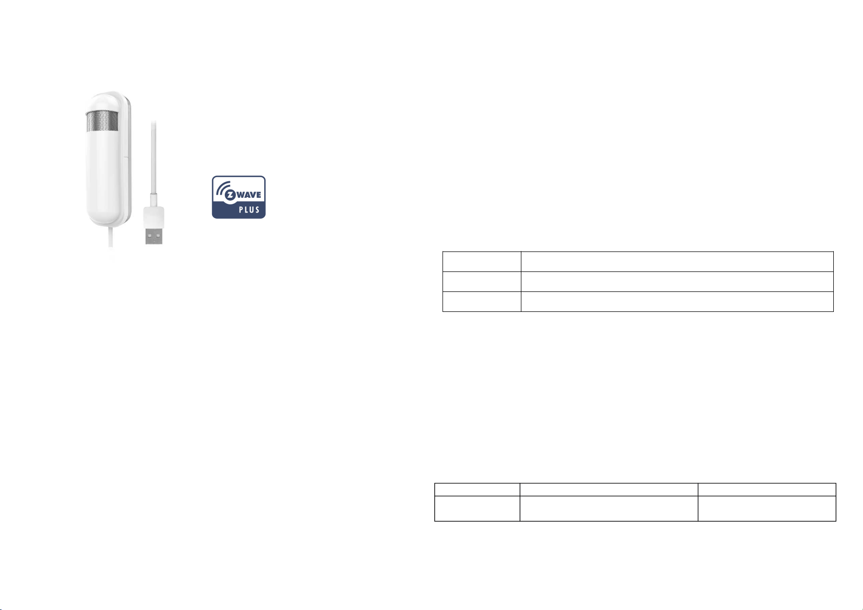
PAT12
system is made by Z-WaveTM 500 series devices. This network system has the
following advantages:
CO2 Sensor A/B
The product supports the Over The Air (OTA) feature for the products firmware
upgrade.
Notice:
The PAT12 may exhibit a tolerance addition of 90ppm when first installed. This will get
corrected by the Self Calibration Feature within the first weeks of operation.
Please continue to operate the PAT12 at a condition that was exposed, ambient
reference levels of air at 400 ppm CO2, for at least 7-Days.
Opening external windows can drop the CO2 levels down to 400ppm.
Function Compare A/B
CO2 Accuracy
The PAT12 CO2 sensor uses advanced NDIR (Non Dispersive Infra-Red) detect
technology. The major advantages of NDIR sensors are low life cycle cost and
precise and stable long-term operation.
The PAT12 CO2 sensor is a device that allows you to check the air quality in your
home by detecting and measuring CO2 concentrations.
The PAT12 sensor is easy to use and very convenient for your home. Just set the
sensor on the wall in the rooms you would like to control, and you are ready to go.
Moreover, the PAT12 can be integrated to other Z-Wave certified devices, and
controlled with Philio app “Home Mate 2.” You can now protect your family and your
business and make sure that air you are breathing is safe. Set up your PAT12 to send
regular notifications and take control even when not at home.
This product can be included and operated in any Z-WaveTM network with other ZWaveTM certified devices from other manufacturers and/or other applications. All nonbattery operated devices within the network will act as repeaters regardless of vendor
to increase reliability of the network.
The device adopts the Z-WaveTM 500 series chip when your Z-WaveTM network
PAT12-A 400-5000 ppm +/- 75 ppm or 10% of reading, whichever is greater
PAT12-B 400-5000 ppm +/- 30 ppm or 3% of reading, whichever is greater
Adding to Z-WaveTM Network
This product can be operated in any Z-Wave network with other Z-Wave certified devices from other manufacturers. All non-battery operated nodes within the network will
act as repeaters regardless of vendor to increase reliability of the network.
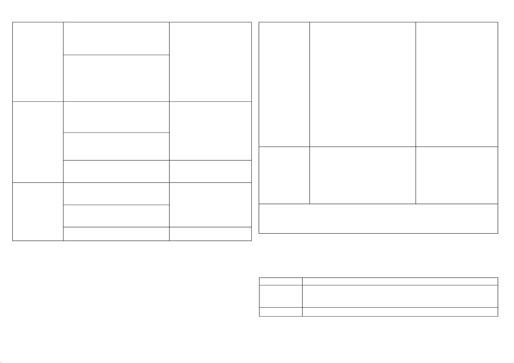
The table below lists an operation summary of basic Z-Wave functions. Please refer
to the instructions for your Z-WaveTM Certificated Primary Controller to access the
Setup function, and to Add/Remove/associate devices
Function Description Annotation
No node ID The Z-Wave Controller does not allocate
a node ID to the Switch.
LED light will flash for 30
seconds.
1
Page 2
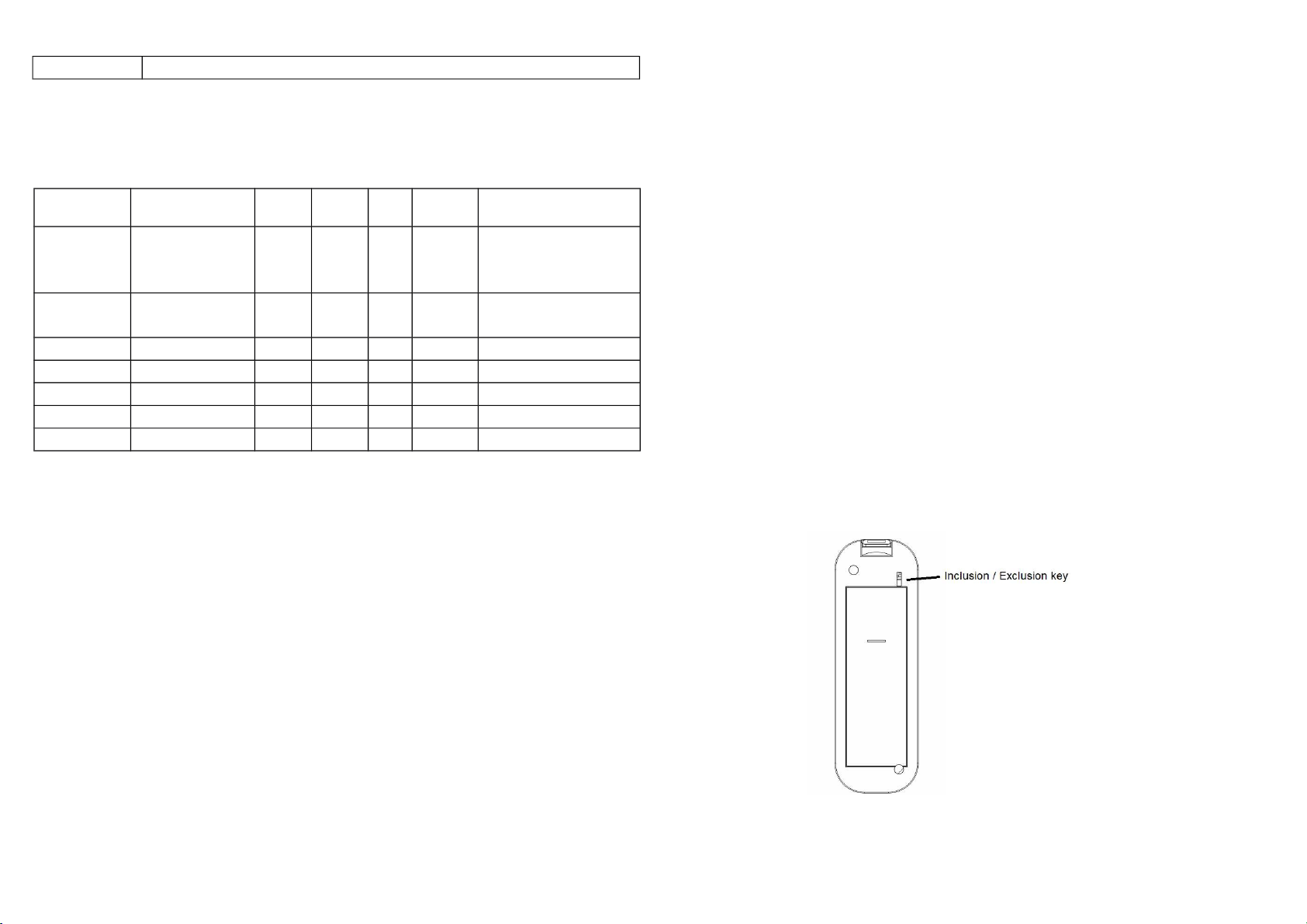
Add
(Inclusion)
Remove
(Exclusion)
Reset 1.Press the include button of the PAT12
1. Set your Z-Wave controller into
inclusion mode by following the
instructions provided by the con-
troller manufacturer.
2. Press the include button of the
PAT12 three times within 3
seconds to enter inclusion
mode.
If the learning code is successful, the
LED light will flash slowly.
1. Put your Z-Wave controller into
exclusion mode by following the
instructions provided by the
controller manufacturer.
2.
Press the include button of the
PAT12 three times within 3
seconds to enter exclusion
mode.
3. Node ID has been excluded.
three times within 3 seconds to enter
inclusion mode.
2.Within 1 second, again press the
include button of the PAT12 for 5
seconds.
3.IDs will get excluded.
LED light will flash slowly.
LED light will flash for 30
seconds.
Use this procedure only in
the event that the primary
controller is lost or otherwise in-
operable.
SmartStart 1. Product has a DSK string, you can
key in the first five digits to begin
with the smart start process, or you
can scan QR code.
Ex: mydsk
10209-46687-52248-13629-04783-
07465-15776-56519
2. SmartStart enabled products can be
added into a Z-Wave network by
scanning the Z-Wave QR Code
present on the product providing. No
further action is required and the
SmartStart product will be added
automatically within 10 minutes of
the network vicinity.
Association
Adding a node ID allocated by Z-Wave Controller means inclusion. Removing a node
ID allocated by Z-Wave Controller means exclusion.
Failed or success in including/excluding the node ID can be viewed from the Z-Wave
Controller.
This machine provides a group of nodes.
Each group can set 5 Nodes.
Group 1: Used for returned events.
Report type:
1.Notification report
2.Sensor multilevel report
3.Reset report
LED Indication
To distinguish what mode the switch is in, view the LED light description for
identification.
State Type LED Indication
No node ID Under normal operation, when the Switch has not been allocated a node ID,
the LED light will flash on and off alternately at 30 second intervals. By
pressing On/Off button, the light will stop flashing temporarily.
Learning When the PAT12 is in learning mode, if the learning code is successful, the
2
Page 3
LED light will flash slowly.
Programming
2. Z-Wave’s Configuration
Configuration
Parameter
1
2
3
4
5
6
7
2. Firmware update over the air (OTA)
PAT12 is based on 500 series SoC and supports Firmware Update Command
Class, it can receive updated firmware images sent by a controller via the Z-wave
RF media. It is a helpful and convenient way to improve functions, if needed.
Function Size
(Byte)
Fixed timer for re-
port Co2 concen-
tration
Concentration
change report
Baseline level 1
Baseline level 2
Baseline level 3
Baseline level 4
Baseline level 5
1 0-127 1 Units of 1 minute.
1 0-100 10 Units of 1 %.
1 0-50 6 Units of 100 ppm.
1 0-50 8 Units of 100 ppm.
1 0-50 10 Units of 100 ppm.
1 0-50 12 Units of 100 ppm.
1 0-50 16 Units of 100 ppm.
Value Unit Default Description
COMMAND_CLASS_MANUFACTURER_SPECIFIC,
COMMAND_CLASS_DEVICE_RESET_LOCALLY,
COMMAND_CLASS_POWERLEVEL,
COMMAND_CLASS_SECURITY_2,
COMMAND_CLASS_CONFIGURATION,
COMMAND_CLASS_NOTIFICATION_V3,
COMMAND_CLASS_SECURITY,
COMMAND_CLASS_SENSOR_MULTILEVEL_V11,
COMMAND_CLASS_SUPERVISION
COMMAND_CLASS_FIRMWARE_UPDATE_MD_V2
Over The Air (OTA) Firmware Update
The device supports Z-Wave firmware update via OTA.
Before starting the update, please remove the front case of the device otherwise the
hardware check will fail.
Let the controller into firmware update mode, and press the front tamper key once to
start the update.
After firmware download is complete, the LED light will flash intermittently.
Overview
Command Classes
The Sensor supports Command Classes including…
COMMAND_CLASS_ZWAVEPLUS_INFO,
COMMAND_CLASS_ASSOCIATION,
COMMAND_CLASS_ASSOCIATION_GRP_INFO,
COMMAND_CLASS_TRANSPORT_SERVICE_V2,
COMMAND_CLASS_VERSION,
3
Page 4
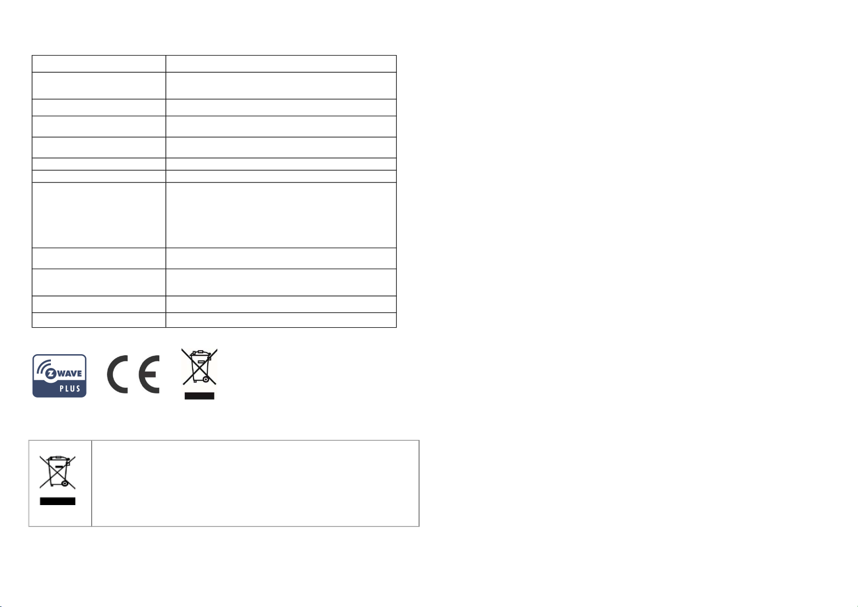
Specification
Rated Voltage DC 5V/1A from USB
Range Minimum 40M in door and 100M in outdoor line of
sight
Operating Temperature -10°C ~ 40°C (85% humidity)
Storage Temperature
Location
Dimension 65(L) x 44.1 (W) x 56.3 (H) mm
CO2 0-5000ppm
Frequency Range
RF Maximum Power (peak)
RF Maximum Power
(Average)
RF Modulation Type FSK (Frequency-Shift Keying)
FCC ID RHHPAT12
-20 C ~ 60°C
Indoor use only
868.40MHz; 869.85MHz (EU)
908.40MHz; 916.00MHz (USA/Canada)
916MHz (Israel)
922.5MHz, 923.9MHz, 926.3MHz (JP)
+5dBm (peak) for EU RED directive
-10dBm (Average) for EU RED directive
Philio Technology Corporation
8F., No.653-2, Zhongzheng Rd., Xinzhuang Dist., New Taipei City 24257, Taiwan
www.philio-tech.com
FCC Interference Statement
This equipment has been tested and found to comply with the limits for a Class B
digital device, pursuant to Part 15 of the FCC Rules. These limits are designed to
provide reasonable protection against harmful interference in a residential installation.
This equipment generates, uses and can radiate radio frequency energy and, if not
installed and used in accordance with the instructions, may cause harmful
interference to radio communications. However, there is no guarantee that
interference will not occur in a particular installation. If this equipment does cause
harmful interference to radio or television reception, which can be determined by
turning the equipment off and on, the user is encouraged to try to correct the
interference by one of the following measures:
•Reorient or relocate the receiving antenna.
•Increase the separation between the equipment and receiver.
•Connect the equipment into an outlet on a circuit different from that to which the
receiver is connected.
•Consult the dealer or an experienced radio/TV technician for help.
Disposal
This marking indicates that this product should not be disposed with
other household wastes throughout the EU. To prevent possible harm to
the environment or human health from uncontrolled waste disposal,
recycle it responsibly to promote the sustainable reuse of material
resources. To return your used device, please use the return and
collection systems or contact the retailer where the product was
purchased. They can take this product for environmental safe recycling.
This device complies with Part 15 of the FCC Rules. Operation is subject to the
following two conditions:
(1) This device may not cause harmful interference, and
(2) This device must accept any interference received, including interference that may
cause undesired operation.
FCC Caution: Any changes or modifications not expressly approved by the party
responsible for compliance could void the user's authority to operate this equipment.
This transmitter must not be co-located or operating in conjunction with any other
antenna or transmitter.
4
Page 5

Warning
Do not dispose of electrical appliances as unsorted municipal waste, use separate
collection facilities. Contact your local government for information regarding the
collection systems available. If electrical appliances are disposed of in landfills or
dumps, hazardous substances can leak into the groundwater and get into the food
chain, damaging your health and well-being.
When replacing old appliances with new once, the retailer is legally obligated to take
back your old appliance for disposal at least for free of charge.
5
 Loading...