


OPERATING INSTRUCTIONS
TCP 350
Electronic Drive Unit
EN
Translation of the original instructions
PT 0092 BEN/O (1703)

Table of contents
Table of contents
1 About this manual . . . . . . . . . . . . . . . . . . . . . . . . . . . . . . . . . . . . . . . . . . . . . . . 5
2 Safety . . . . . . . . . . . . . . . . . . . . . . . . . . . . . . . . . . . . . . . . . . . . . . . . . . . . . . . . . 7
3 Product description. . . . . . . . . . . . . . . . . . . . . . . . . . . . . . . . . . . . . . . . . . . . . . 9
4 Wiring diagrams . . . . . . . . . . . . . . . . . . . . . . . . . . . . . . . . . . . . . . . . . . . . . . . 11
5 Installation . . . . . . . . . . . . . . . . . . . . . . . . . . . . . . . . . . . . . . . . . . . . . . . . . . . . 14
6 The Pfeiffer Vacuum parameter set . . . . . . . . . . . . . . . . . . . . . . . . . . . . . . . . 22
1.1 Validity. . . . . . . . . . . . . . . . . . . . . . . . . . . . . . . . . . . . . . . . . . . . . . . . . . . . . 5
1.2 Conventions . . . . . . . . . . . . . . . . . . . . . . . . . . . . . . . . . . . . . . . . . . . . . . . . 5
1.2.1 Safety instructions . . . . . . . . . . . . . . . . . . . . . . . . . . . . . . . . . . . . . . 5
1.2.2 Pictographs . . . . . . . . . . . . . . . . . . . . . . . . . . . . . . . . . . . . . . . . . . . 6
1.2.3 Instructions in the text . . . . . . . . . . . . . . . . . . . . . . . . . . . . . . . . . . . 6
1.2.4 Abbreviations . . . . . . . . . . . . . . . . . . . . . . . . . . . . . . . . . . . . . . . . . 6
2.1 Safety precautions . . . . . . . . . . . . . . . . . . . . . . . . . . . . . . . . . . . . . . . . . . . 7
2.2 Proper use . . . . . . . . . . . . . . . . . . . . . . . . . . . . . . . . . . . . . . . . . . . . . . . . . 8
2.3 Improper use. . . . . . . . . . . . . . . . . . . . . . . . . . . . . . . . . . . . . . . . . . . . . . . . 8
3.1 Product identification. . . . . . . . . . . . . . . . . . . . . . . . . . . . . . . . . . . . . . . . . . 9
3.1.1 Scope of delivery. . . . . . . . . . . . . . . . . . . . . . . . . . . . . . . . . . . . . . . 9
3.2 Function . . . . . . . . . . . . . . . . . . . . . . . . . . . . . . . . . . . . . . . . . . . . . . . . . . . 9
3.3 Range of application . . . . . . . . . . . . . . . . . . . . . . . . . . . . . . . . . . . . . . . . . 10
3.3.1 Cooling . . . . . . . . . . . . . . . . . . . . . . . . . . . . . . . . . . . . . . . . . . . . . 10
3.4 Connection panel . . . . . . . . . . . . . . . . . . . . . . . . . . . . . . . . . . . . . . . . . . . 10
4.1 TCP 350 with connecting cable and M12 accessories connector. . . . . . . 11
4.2 TCP 350 with connecting cable and M8 accessories connector. . . . . . . . 12
4.3 TCP 350 with connecting cable and RJ45 accessories connector . . . . . . 13
5.1 Assembly . . . . . . . . . . . . . . . . . . . . . . . . . . . . . . . . . . . . . . . . . . . . . . . . . 14
5.1.1 Rack installation . . . . . . . . . . . . . . . . . . . . . . . . . . . . . . . . . . . . . . 14
5.2 Connections . . . . . . . . . . . . . . . . . . . . . . . . . . . . . . . . . . . . . . . . . . . . . . . 14
5.3 Connection "external pump" . . . . . . . . . . . . . . . . . . . . . . . . . . . . . . . . . . . 15
5.4 Earthing. . . . . . . . . . . . . . . . . . . . . . . . . . . . . . . . . . . . . . . . . . . . . . . . . . . 16
5.5 Accessory connection . . . . . . . . . . . . . . . . . . . . . . . . . . . . . . . . . . . . . . . . 16
5.6 Connection "RS-485" . . . . . . . . . . . . . . . . . . . . . . . . . . . . . . . . . . . . . . . . 17
5.6.1 Connections . . . . . . . . . . . . . . . . . . . . . . . . . . . . . . . . . . . . . . . . . 17
5.6.2 Cross-linking via the connection RS-485 . . . . . . . . . . . . . . . . . . . 17
5.7 "SERVICE" connection . . . . . . . . . . . . . . . . . . . . . . . . . . . . . . . . . . . . . . . 18
5.7.1 Connections . . . . . . . . . . . . . . . . . . . . . . . . . . . . . . . . . . . . . . . . . 18
5.8 Connection "REMOTE". . . . . . . . . . . . . . . . . . . . . . . . . . . . . . . . . . . . . . . 18
5.8.1 Pin assignment . . . . . . . . . . . . . . . . . . . . . . . . . . . . . . . . . . . . . . . 18
5.8.2 +24 V DC* Output / Pin 1 . . . . . . . . . . . . . . . . . . . . . . . . . . . . . . . 19
5.8.3 Inputs . . . . . . . . . . . . . . . . . . . . . . . . . . . . . . . . . . . . . . . . . . . . . . 19
5.8.4 Outputs . . . . . . . . . . . . . . . . . . . . . . . . . . . . . . . . . . . . . . . . . . . . . 20
5.8.5 Relay contacts. . . . . . . . . . . . . . . . . . . . . . . . . . . . . . . . . . . . . . . . 20
5.9 Connecting a measuring device . . . . . . . . . . . . . . . . . . . . . . . . . . . . . . . . 21
5.10 Connecting to the mains power supply . . . . . . . . . . . . . . . . . . . . . . . . . . . 21
6.1 General . . . . . . . . . . . . . . . . . . . . . . . . . . . . . . . . . . . . . . . . . . . . . . . . . . . 22
6.1.1 Conventions . . . . . . . . . . . . . . . . . . . . . . . . . . . . . . . . . . . . . . . . . 22
6.2 Parameter overview . . . . . . . . . . . . . . . . . . . . . . . . . . . . . . . . . . . . . . . . . 22
6.2.1 Annotation . . . . . . . . . . . . . . . . . . . . . . . . . . . . . . . . . . . . . . . . . . . 22
6.2.2 Control commands . . . . . . . . . . . . . . . . . . . . . . . . . . . . . . . . . . . . 22
6.2.3 Status requests . . . . . . . . . . . . . . . . . . . . . . . . . . . . . . . . . . . . . . . 23
6.2.4 Set value settings . . . . . . . . . . . . . . . . . . . . . . . . . . . . . . . . . . . . . 24
2

Table of contents
7 Operation . . . . . . . . . . . . . . . . . . . . . . . . . . . . . . . . . . . . . . . . . . . . . . . . . . . . . 25
7.1 Switching on . . . . . . . . . . . . . . . . . . . . . . . . . . . . . . . . . . . . . . . . . . . . . . . 25
7.1.1 Self-test . . . . . . . . . . . . . . . . . . . . . . . . . . . . . . . . . . . . . . . . . . . . . 25
7.2 LC-Display . . . . . . . . . . . . . . . . . . . . . . . . . . . . . . . . . . . . . . . . . . . . . . . . 25
7.3 Symbol description . . . . . . . . . . . . . . . . . . . . . . . . . . . . . . . . . . . . . . . . . . 26
7.4 Key functions . . . . . . . . . . . . . . . . . . . . . . . . . . . . . . . . . . . . . . . . . . . . . . 26
7.5 Operation . . . . . . . . . . . . . . . . . . . . . . . . . . . . . . . . . . . . . . . . . . . . . . . . . 27
7.5.1 Selecting the parameters . . . . . . . . . . . . . . . . . . . . . . . . . . . . . . . 27
7.5.2 Set parameters . . . . . . . . . . . . . . . . . . . . . . . . . . . . . . . . . . . . . . . 27
7.6 Configuring the connections . . . . . . . . . . . . . . . . . . . . . . . . . . . . . . . . . . . 28
7.6.1 DO2 and relay on "REMOTE" . . . . . . . . . . . . . . . . . . . . . . . . . . . . 28
7.6.2 Analog output on "REMOTE" . . . . . . . . . . . . . . . . . . . . . . . . . . . . 28
7.6.3 Accessory connection . . . . . . . . . . . . . . . . . . . . . . . . . . . . . . . . . . 28
8 Operation with the Pfeiffer Vacuum parameter set . . . . . . . . . . . . . . . . . . . 29
8.1 General . . . . . . . . . . . . . . . . . . . . . . . . . . . . . . . . . . . . . . . . . . . . . . . . . . . 29
8.1.1 Factory settings . . . . . . . . . . . . . . . . . . . . . . . . . . . . . . . . . . . . . . . 29
8.1.2 Checking the adjustments . . . . . . . . . . . . . . . . . . . . . . . . . . . . . . . 29
8.1.3 Keypad lock. . . . . . . . . . . . . . . . . . . . . . . . . . . . . . . . . . . . . . . . . . 29
8.2 Rotation speed set value . . . . . . . . . . . . . . . . . . . . . . . . . . . . . . . . . . . . . 29
8.3 Remote control . . . . . . . . . . . . . . . . . . . . . . . . . . . . . . . . . . . . . . . . . . . . . 30
8.3.1 Standard operation . . . . . . . . . . . . . . . . . . . . . . . . . . . . . . . . . . . . 30
8.3.2 REMOTE Priority ON . . . . . . . . . . . . . . . . . . . . . . . . . . . . . . . . . . 30
8.3.3 REMOTE Priority OFF . . . . . . . . . . . . . . . . . . . . . . . . . . . . . . . . . 30
8.4 Gas type dependent operations . . . . . . . . . . . . . . . . . . . . . . . . . . . . . . . . 30
8.5 Run-up time . . . . . . . . . . . . . . . . . . . . . . . . . . . . . . . . . . . . . . . . . . . . . . . 31
8.6 Adjusting the rotation speed switchpoint. . . . . . . . . . . . . . . . . . . . . . . . . . 31
8.7 Rotation speed setting mode . . . . . . . . . . . . . . . . . . . . . . . . . . . . . . . . . . 31
8.8 Standby. . . . . . . . . . . . . . . . . . . . . . . . . . . . . . . . . . . . . . . . . . . . . . . . . . . 32
8.9 Operation mode backing pump. . . . . . . . . . . . . . . . . . . . . . . . . . . . . . . . . 32
8.9.1 Continous operation . . . . . . . . . . . . . . . . . . . . . . . . . . . . . . . . . . . 32
8.9.2 Intermittend operation (diaphragm pumps only) . . . . . . . . . . . . . . 32
8.10 Operation with accessories. . . . . . . . . . . . . . . . . . . . . . . . . . . . . . . . . . . . 33
8.10.1 Air cooling/heating. . . . . . . . . . . . . . . . . . . . . . . . . . . . . . . . . . . . . 34
8.10.2 Vent modes . . . . . . . . . . . . . . . . . . . . . . . . . . . . . . . . . . . . . . . . . . 34
8.11 Pressure measurement. . . . . . . . . . . . . . . . . . . . . . . . . . . . . . . . . . . . . . . 35
8.11.1 Displaying the gauge type . . . . . . . . . . . . . . . . . . . . . . . . . . . . . . . 35
8.11.2 Displaying the active pressure value. . . . . . . . . . . . . . . . . . . . . . . 35
8.12 Monitoring the thermal load . . . . . . . . . . . . . . . . . . . . . . . . . . . . . . . . . . . 35
8.13 Switching on/off the pump. . . . . . . . . . . . . . . . . . . . . . . . . . . . . . . . . . . . . 36
8.13.1 Switching on . . . . . . . . . . . . . . . . . . . . . . . . . . . . . . . . . . . . . . . . . 36
8.13.2 Switching off . . . . . . . . . . . . . . . . . . . . . . . . . . . . . . . . . . . . . . . . . 36
9 Pfeiffer Vacuum Protocol for "RS-485" . . . . . . . . . . . . . . . . . . . . . . . . . . . . . 37
9.1 Telegram frame. . . . . . . . . . . . . . . . . . . . . . . . . . . . . . . . . . . . . . . . . . . . . 37
9.2 Telegrams . . . . . . . . . . . . . . . . . . . . . . . . . . . . . . . . . . . . . . . . . . . . . . . . . 37
9.2.1 Example 1 . . . . . . . . . . . . . . . . . . . . . . . . . . . . . . . . . . . . . . . . . . . 37
9.2.2 Example 2 . . . . . . . . . . . . . . . . . . . . . . . . . . . . . . . . . . . . . . . . . . . 38
9.3 Applied data types . . . . . . . . . . . . . . . . . . . . . . . . . . . . . . . . . . . . . . . . . . 38
10 Malfunctions . . . . . . . . . . . . . . . . . . . . . . . . . . . . . . . . . . . . . . . . . . . . . . . . . . 39
10.1 General . . . . . . . . . . . . . . . . . . . . . . . . . . . . . . . . . . . . . . . . . . . . . . . . . . . 39
10.2 Operation display via LED . . . . . . . . . . . . . . . . . . . . . . . . . . . . . . . . . . . . 39
10.2.1 Operation display via LED. . . . . . . . . . . . . . . . . . . . . . . . . . . . . . . 39
10.3 Error codes . . . . . . . . . . . . . . . . . . . . . . . . . . . . . . . . . . . . . . . . . . . . . . . . 39
11 Accessories . . . . . . . . . . . . . . . . . . . . . . . . . . . . . . . . . . . . . . . . . . . . . . . . . . . 40
3

Table of contents
12 Technical data and dimensions . . . . . . . . . . . . . . . . . . . . . . . . . . . . . . . . . . . 41
12.1 Technical data. . . . . . . . . . . . . . . . . . . . . . . . . . . . . . . . . . . . . . . . . . . . . . 41
12.2 Dimensions . . . . . . . . . . . . . . . . . . . . . . . . . . . . . . . . . . . . . . . . . . . . . . . . 41
Declaration of conformity . . . . . . . . . . . . . . . . . . . . . . . . . . . . . . . . . . . . . . . . 42
4

1 About this manual
1.1 Validity
This operating manual is for customers of Pfeiffer Vacuum. It describes the functioning
of the designated product and provides the most important information for safe use of
the unit. The description follows applicable EU guidelines. All information provided in this
operating manual refers to the current state of the product's development. The documentation remains valid as long as the customer does not make any changes to the product.
Up-to-date operating instructions can also be downloaded from
www.pfeiffer-vacuum.com.
1.2 Conventions
1.2.1 Safety instructions
The safety instructions in Pfeiffer Vacuum operating instructions are the result of risk
evaluations and hazard analyses and are oriented on international certification standards as specified by UL, CSA, ANSI Z-535, SEMI S1, ISO 3864 and DIN 4844. In this
document, the following hazard levels and information are considered:
About this manual
DANGER
Imminent danger
Indicates an imminent hazardous situation that will result in death or serious injury.
WARNING
Possibly imminent danger
Indicates an imminent hazardous situation that can result in death or serious injury.
CAUTION
Possibly imminent danger
Indicates an imminent hazardous situation that can result in minor or moderate injury.
NOTICE
Command or note
Command to perform an action or information about properties, the disregarding of
which may result in damage to the product.
5

About this manual
1.2.2 Pictographs
1.2.3 Instructions in the text
Prohibition of an action to avoid any risk of accidents, the disregarding
of which may result in serious accidents
Warning of a displayed source of danger in connection with operation of
the unit or equipment
Command to perform an action or task associated with a source of danger, the disregarding of which may result in serious accidents
Important information about the product or this document
1.2.4 Abbreviations
Work instruction: here you have to do something.
TCP: Electronic drive unit for turbopump, external with power supply
TC: Electronic drive unit for turbopump
DI / DO: Digital input / digital output
AI / AO: Analog input / analog output
[P:000]: Parameter of the electronic drive unit with number
6

2Safety
2.1 Safety precautions
Duty to inform
Each person involved in the installation or operation of the unit must read and observe
the safety-related parts of these operating instuctions.
The operator is obligated to make operating personnel aware of dangers originating
from the unit or the entire system.
Danger of unsafe electrical installation
Safe operation after installation is the responsibility of the operator.
Do not independently modify or change the pump and electrical equipment.
Make sure that the system is integrated in an emergency off safety circuit.
Consult Pfeiffer Vacuum for special requirements.
Danger of electric shock
In case of defect, the parts connected to the mains supply are under voltage.
Always keep the mains connection freely accessible so that you can disconnect it at
any time.
Safety
WARNING
WARNING
WARNING
Automatic start-up after power failure or malfunction acknowledgement
The function "pumping station" of the electronic drive unit remains active after power
failure or errors that lead to shut down the pump or the system. The turbopump runs up
automatically after power ist restored or malfunction acknowledgement.
Switch off the function "pumping station" if necessary.
Provide safety measures against interference in the high vacuum flange while the tur-
bopump is running.
CAUTION
Automatic start
After bridging the contacts Pin 1, 3, 4 on the connection "REMOTE" and setting up the
supply voltage, the turbopump will run up immediately.
Switch on the mains supply on the turbopump immediately before operation.
NOTICE
Damages to the pump and drive
Even after the mains power is switched off, the subsequently running pump delivers
electric power to the electronic drive unit. There is a danger of electric body contact by
premature separating the pump from the electronic drive unit.
Never separate the electronic drive unit from the pump when the mains power is con-
nected or the rotor is running.
● Observe all safety and accident prevention regulations.
● Always ensure a safe connection to the protective earthing conductor (PE, protection
class I).
● Regularly check the proper observance of all safety measures.
● Before carrying out any work disconnect the unit and all associated installations safely
from the mains.
● Do not loosen any plug connection during operations.
7

Safety
2.2 Proper use
● The unit has been accredited with protection class IP 20. Take necessary measures
when installing into ambient conditions, which afford other protection classes.
● Use as a desktop unit is only possible with a suitable cover.
● Observe fire protection specifications according IEC 61010 when installing in hous-
ings.
● Keep leads and cables well away from hot surfaces (> 70 °C).
● Only separate the pump and the electronic drive unit from each other after disconnect-
ing the supply voltage and the complete standstill of the pump.
NOTICE
EC conformity
The manufacturer's declaration of conformity becomes invalid if the operator modifies
the original product or installs additional components.
Following installation into a plant and before commissioning, the operator must check
the entire system for compliance with the valid EU directives and reassess it accordingly.
● The external electronic drive units TCP 350 are used exclusively for operating
HiPace® and CompactTurbo series Pfeiffer Vacuum turbopumps with a capacity of ≤
800 l/s.
● The external electronic drive unit TCP 350 serves as voltage supply, control and monitoring of a turbopump and connected peripherals.
● Only operate the pump with the respective electronic drive unit. The use of other than
the intended electronic drive units is not permitted.
2.3 Improper use
Improper use will cause all claims for liability and warranties to be forfeited. Improper use
is defined as usage for purposes deviating from those mentioned above, especially:
● connection to pumps or units which are not suitable for this purpose according to their
operating instructions
● connection to units which have exposed voltage-carrying parts
● connection to mains supplies, which do not confirm to the regulations IEC 61010 or
IEC 60950
● operation of the devices in areas with ionizing radiation
8

3 Product description
Mod: T CP 350
Mod.-Nr.: PM C01 740
Input: 115/230V -20/+15% 420 VA
Outpu t: 0 - 72 V 6,5 VA
0-1500 Hz
Made in Germany 2014/08
Ser. Nr.:78514xxx
TCP 350
1
2
3
6
8
4
9
10
11
7
5
3.1 Product identification
● The external electronic drive unit TCP 350 serves as voltage supply, control and monitoring of a turbopump and connected peripherals.
● For total pressure measurement the connection of a vacuum gauge is possible.
Characteristics TCP 350
Connection panel Standard
HiPace turbopump, suitable for TCP 80, 300, 400, 700, 800
Mains requirement: frequency (range) 50/60 Hz
Mains requirement: voltage (range) 100-120/200-240 (± 10%) V AC
Current consumption max. 4 A
Max. power consumption 420 VA
Mains requirement: internal fuse 5 A, slow blow
To correctly identify the product when communicating with Pfeiffer Vacuum, always have
the information from the rating plate available.
Product description
3.1.1 Scope of delivery
3.2 Function
Mod: TC P 350
Mod.-Nr.: PM C01 740
Input: 115/230V -20/+15% 420 VA
Output: 0 - 72 V 6,5 A
0-1500 Hz
Made in Germany 2014/08
Fig. 1: Example for a rating plate
Ser. Nr.:78514xxx
● TCP 350, external electronic drive unit for turbopumps
● Mating plug for the connection "REMOTE" on the TCP 350 (type dependent)
● Fixing materials
● Operating instructions
Fig. 2: TCP 350, Overview of controls and connections
1 LC display, illuminated
2Status icons
3 LEDs "Operation indicator"
4 Controls
5 Mains connection and main switch
6 "PUMP" connection
7 "REMOTE" connection
8 "RS485" connection
9 "SERVICE" connection
10 "GAUGE" connection
11 Earth connection PE
9

Product description
A
B
C
E
FG
H
J
K
L
M
NP
UVR
S
T
D
1
2
3
4
5
6
3.3 Range of application
3.3.1 Cooling
Pfeiffer Vacuum electronic drive units TCP 350 must be installed and operated in the following ambient conditions.
Installation location weather protected (indoors)
Protection category IP 20
Protection class I
Temperature +5 °C to +40 °C
Relative humidity max. 80 %, at T 31 °C, max. 50% at T 40 °C
Atmospheric pressure: 750 hPa - 1060 hPa
Installation altitude 2000 m max.
Degree of pollution 2
Overvoltage category II
Remarks to ambient conditions
The specified permissible ambient temperatures apply to operation of the turbopump at
maximum permissible fore-vacuum pressure or at maximum gas throughput depending
on the cooling method. The turbopump is intrinsically safe by a redundant temperature
monitoring.
● By reducing the fore-vacuum pressure or gas throughput, the turbopump can be op-
erated at higher ambient temperatures.
● If the maximum permissible operating temperature of the turbopump is exceeded, the
electronic drive unit reduces drive power first and switches off then, if necessary.
3.4 Connection panel
POWER/AC input
C14 device connector for connecting a power cable with a C13 socket type from
the Pfeiffer Vacuum accessories program.
PUMP
Round plug connection, socket, 19-pin with three-point bayonet coupling for con-
necting a Pfeiffer Vacuum turbopump with connection cables of various lengths
(max. 110 m in the standard version).
REMOTE
High Density D-Sub connector, 26-pin for connecting and configuring a remote
control.
RS485
RJ45 plug contact, 8-pin for connecting Pfeiffer Vacuum control devices (e.g.,
HPU) or a PC.
SERVICE
RJ45 plug contact, 8-pin. This interface is used exclusively for Pfeiffer Vacuum
Service purposes.
GAUGE
Round plug connection, socket, 6-pin for pressure measuring for connecting an
analog Pfeiffer Vacuum transmitter from the Active Line series.
10

Wiring diagrams
4 Wiring diagrams
4.1 TCP 350 with connecting cable and M12 accessories connector
M
Fan
3
452
1
VAC
Mains input,
L
Heating
115/208/230
N
PE
N
PE
L
Identification
Ground
Ground signal
Gauges
TPR2XX/ PKR2XX/
CMR2XX/ ACR2XX/IKR2XX
1
2
346
GAUGE
12346
Pressure signal
TCP 350
123456789
REMOTE
PE
Supply voltage
5
5
11
12131415161718
10
Rf1
Turbopump HiPace®
BCDEFGH
A
TMP
PUMP
A
BCDEFGH
Rf1
Ground
19
{
ϑ
Rf2
{
Rf2
PTC
Motorphases
N.C.
N.C.
N.C.
N.C.N.C.
2021222324
{
Oilsensor
N.C.
N.C.
26
25
Relay box Heating
345
A1
J
L
+24VDC
RS485
221
N
Heat/TMS
Sensor
12345
Venting Valve
134
5
B1
RL
10 Ohm/m
M
Vent
Ground
PV-Service only
PV-Service only
RS232 receive
1
SERVICE
2
3
8
7
PV-Service only
PV-Service only
RS232 transmitt
566
4
8
7
P
V
R
N.C.
N.C.
Power
PV-Service only
RL
PE
L
N
PE
AC-INPUT
S
K
T
U
N.C.
N.C.
N.C.
+24VDC*
Venting on
Motor TMP on
Pumping Station on
Standby on
Switching output 2
Set rot speed 0-10V
N.C.
Heating on
FV-Pump
Switching output 1
Error Acknowledge
Remote priority
Uf/ Ui/ Up voltage
Relaiscontacts
switching point
Relaiscontacts
errormessage
{
contacts
Potentialfree
GND*
+24VDC*
N.C.
N.C.
N.C.
D+
GND*
D-
N.C.
N.C.
N.C.
RXD
N.C.
TXD.
GND*
N.C.
N.C.
Mains input
(90-135/185-265) VAC
11

Wiring diagrams
12346
5
A
BCDEFGH
L
R
V
M
J
P
K
N
S
T
U
Ground
Oilsensor
Motorphases
PTC
Rf1
Rf2
+24VDC
Heat/TMS
Sensor
Vent
N.C.
RL
PE
N.C.
N.C.
N.C.
Mains input
(90-135/185-265) VAC
L
N
PE
Power
{
TCP 350
SERVICE
RS485
REMOTE
AC-INPUT
12345
566
7
8
1
2
3
4
7
8
+24VDC*
Venting on
Motor TMP on
Pumping Station on
Standby on
Heating on
Uf/ Ui/ Up voltage
Set rot speed 0-10V
Switching output 1
Switching output 2
N.C.
FV-Pump
Error Acknowledge
Remote priority
{
{
{
GND*
Relaiscontacts
switching point
Relaiscontacts
errormessage
Potentialfree
contacts
123456789
10
11
12131415161718
19
2021222324
26
25
N.C.
N.C.
N.C.
N.C.
+24VDC*
GND*
D+
D-
TXD.
N.C.
N.C.
N.C.
GND*
N.C.
N.C.
RXD
N.C.
N.C.
N.C.
N.C.
N.C.
N.C.N.C.
N.C.
Ground
RS232 transmitt
RS232 receive
PV-Service only
PV-Service only
PV-Service only
PV-Service only
PV-Service only
Identification
Ground
Pressure signal
Ground signal
Supply voltage
PE
1
2
346
5
A
BCDEFGH
Rf1
Rf2
Turbopump HiPace®
Gauges
TPR2XX/ PKR2XX/
CMR2XX/ ACR2XX/IKR2XX
RL
PUMP
B1
TMP
GAUGE
10 Ohm/m
M
341
134
341
Relay box Heating
L
N
N
PE
PE
L
Fan
Venting Valve
Heating
Mains input,
115/208/230
VAC
A1
ϑ
4.2 TCP 350 with connecting cable and M8 accessories connector
12

Wiring diagrams
12346
5
A
BCDEFGH
L
R
V
M
J
P
K
N
S
T
U
Ground
Oilsensor
Motorphases
PTC
Rf1
Rf2
+24VDC
Heat/TMS
Sensor
Vent
N.C.
RL
PE
N.C.
N.C.
N.C.
Mains input
(90-135/185-265) VAC
L
N
PE
Power
{
TCP 350
SERVICE
RS485
REMOTE
AC-INPUT
12345
566
7
8
1
2
3
4
7
8
+24VDC*
Venting on
Motor TMP on
Pumping Station on
Standby on
Heating on
Uf/ Ui/ Up voltage
Set rot speed 0-10V
Switching output 1
Switching output 2
N.C.
FV-Pump
Error Acknowledge
Remote priority
{
{
{
GND*
Relaiscontacts
switching point
Relaiscontacts
errormessage
Potentialfree
contacts
123456789
10
11
12131415161718
19
2021222324
26
25
N.C.
N.C.
N.C.
N.C.
+24VDC*
GND*
D+
D-
TXD.
N.C.
N.C.
N.C.
GND*
N.C.
N.C.
RXD
N.C.
N.C.
N.C.
N.C.
N.C.
N.C.N.C.
N.C.
Ground
RS232 transmitt
RS232 receive
PV-Service only
PV-Service only
PV-Service only
PV-Service only
PV-Service only
M
Identification
Ground
Pressure signal
Ground signal
Supply voltage
PE
1
2
346
5
1
234
665
5
1
234
1
2
3
4
6
5
A
BCDEFGH
Rf1
Rf2
Turbopump 071/261/521
Relay box Heating
L
N
N
PE
PE
L
Gauges
TPR2XX/ PKR2XX/
CMR2XX/ ACR2XX/IKR2XX
RL
Fan
Heating
Mains input,
115/208/230
VAC
PUMP
FAN/HEAT
VENT
TMP
GAUGE
10 Ohm/m
alternative
Venting Valve
ϑ
4.3 TCP 350 with connecting cable and RJ45 accessories connector
13

Installation
5 Installation
5.1 Assembly
5.1.1 Rack installation
NOTICE
Ensure free convection
Incorrect installation can cause damage by over-heating or create a fire hazard.
Maintain a minimum distance of 50 mm from cooling vents to adjacent components
or boundaries.
Install the device upright.
The unit is fitted in a casing that is suitable for installation in 19"/3HE rack modules.
Insert the unit in the guiderails of a 19"/3HE rack and screw on the front panel secure-
ly with four fixing screws provided as part of the scope of supply.
Ensure sufficient air circulation if installed in enclosed housings.
Do not hinder device internal air flow and removal.
Ensure permissible ambient conditions in the rack cabinet (see p. 10, chap. 3.3).
5.2 Connections
Fig. 3: General overview of the connections on the TCP 350
14

5.3 Connection "external pump"
TCP 350
TMP
6
6.1
6.26.3
6.4 6.5
The external connection of a Pfeiffer Vacuum turbopump to the electronic drive unit TCP
350 is possible, using shielded connection cables of different lengths from the Pfeiffer
Vacuum accessories programme.
Danger of electric shock
The system is only free of voltages if the mains plug is disconnected.
Switch off the main switch and disconnect the mains plug before all work.
Secure against unintentional restarting.
Ensure the complete stop of the pump (f < 1).
Risk of tripping!
Risk of tripping when working in the installation area.
Place supply lines in such a way that no tripping hazards occur.
The cable for control and operation of the turbopump is uniquely designated by plugs and
sockets.
● Round connector, 18-pin for connecting to the TCP 350
● Socket, 8-pin with two control cables for accessories and earth cable for connecting
to the turbopump
Installation
WARNING
CAUTION
Connection to existing cable configurations
For special or existing configurations Pfeiffer Vacuum recommends the use of an adapter cable between the TCP 350 and an existing connection cable to the turbopump.
See the accessories recommendations for the turbopump in question.
Fig. 4: Connecting the turbopump to the electronic drive unit TCP 350
6 Connection "pump" to TCP
6.1 TCP connection cable - pump
6.2 Accessories connectors
Install the connection cable between the electronic drive unit and the turbopump.
Lock plug connections and secure the bayonet fittings.
Connect earth cable 6.4 from the connection cable directly with the earth terminal on
the turbopump with the enclosed fastening material 6.5.
6.3 "Pump" connection
6.4 PE earth cable
6.5 Fasteners
15

Installation
M4
5.4 Earthing
Pfeiffer Vacuum recommends to connect an appropriate earthing wire to derive applicative interferences.
Fig. 5: Installing the earthing connection
5.5 Accessory connection
There are two connections (M8, M12 or RJ45) on the TCP 350 - turbopump connecting
cable for the following accessories:
– A1 or FAN/HE AT: Air cooling or heating
200 mA
● I
max
– B1 or VENT: vent valve only
● I
200 mA
max
A1
B1
A1
B1
FAN/HEAT
VENT
TCP 350
Fig. 6: Connection cable TCP 350 - turbopump with variants of the accessory connection
For connection and operation of the accessory please refer to the relevant operating
instructions of the turbopump.
Connect the accessory control cable to the appropriate connection on the connecting
cable.
Configure settings and controls via the interfaces of the electronic drive unit (only ap-
plies to A1, or FAN/HEAT).
Special features:
The connected accessories are activated after commissioning the electronic drive unit.
Use adapters from the Pfeiffer Vacuum accessory range for the turbopump to ensure
compatibility with existing configurations.
Do not connect a relaybox for the backing pump to the connecting cable; instead use
an adapter cable connected to the TCP 350 electronic drive unit "Remote" output.
Use a sealing gas throttle instead of a sealing gas valve.
TMP
16

5.6 Connection "RS-485"
1 ....
D+ D-TCD+ D-TCD+ D-
D+
D-
TIC 001/
USB/RS485-converter
RS 485
5.6.1 Connections
A Pfeiffer Vacuum display and control panel (DCU or HPU) or an external PC can be
connected to the electronic drive unit via the connection designated "RS-485". The interface is electrically isolated from the maximum supply voltage of the electronic drive unit.
The electrical couplings are optically decoupled internally.
Designation Value
Serial interface RS-485
Baud rate 9600 bauds
Data word length 8 bits
Parity none (no parity)
Start bits 1
Stop bits 1
Pin Assignment
1 not connected
2 +24 V output 150 mA max. load
3 not connected
4 not connected
5 RS485 D+
6GND
7 RS485 D8 not connected
The connection of respectively one external operating unit is possible on the interface
RS-485.
A USB interface (PC) can be connected via the USB/RS-485-converter.
Installation
5.6.2 Cross-linking via the connection RS-485
Danger of electric shock
The insulation measures of the bus system are designed only for use with safety extralow voltage.
Connect only suitable devices to the bus system.
Establish the connections according to the specification of the interface RS-485.
Connect all units with RS-485 D+ and RS-485 D- to the bus.
● The group address of the electronic drive unit is 988.
● All units connected to the bus must have differing RS-485 device addresses [P:797].
Connecting to an external bus system
It is only possible to connect to an external bus system (e.g., Profibus DP, DeviceNet)
on devices with a connection gateway TIC 253 or TIC 263. The simultaneous use of the
RS485 interface is not possible in this case.
● The field bus option cannot be retrofitted on the standard device.
CAUTION
17

Installation
1 ....
19
1018
1926
5.7 "SERVICE" connection
5.7.1 Connections
The connection labelled "SERVICE" on the electronic drive unit is used exclusively for
service and configuration purposes. The RS-232 interface is safely electrically isolated
from the maximum supply voltage that can occur in the electronic drive unit. The electrical connections are optically decoupled internally.
Designation Value
Serial interface RS-232
Baud rate 9600 bauds
Data word length 8 bits
Parity none (no parity)
Start bits 1
Stop bits 1..2
Pin Assignment
1 Service only
2 Service only
3 RS 232 RxD
4 RS 232 TxD
5 Service only
6GND
7 Service only
8 Service only
5.8 Connection "REMOTE"
Remote control is possible via the 26-pin D-sub connector labelled "REMOTE" on the
electronic drive unit. The accessible individual functions are mapped to "PLC levels".
Input signals Output signals
– PLC High level: +13 to +33 V DC
– PLC Low level: -33 to +7 V DC
–Ri: 7 kΩ
Table 1: Logic levels of digital inputs and outputs on REMOTE
Shielded connectors and cables must be used.
The following information display the factory setting. Configuration is possible
using the Pfeiffer Vacuum parameter set.
5.8.1 Pin assignment
Pin Function Description, factory setting
1 +24 V DC* output (V+) Reference voltage for all digital inputs and outputs:
2 DI1 Release vents; Low: off; High: on
3 DI motor pump Drive motor; Low: off; High: on
4 DI Pumping station Low: off; High: on
5 DI Standby Standby speed; Low: off; High: on
6 DI2 Heater; Low: off; High: on
7 AI+ rotation speed setting
mode
8 DO1 Speed-control switching point reached;
9 DO2 Low: Fault; High: no faults (I
10 not assigned
11 DO control backing pump Backing pump ON; Low: no; High: yes (I
12 AO voltage Vf, Vp, Vi 0-10 V DC is equivalent to 0-100%; R
13 DI Fault acknowledge-
ment
– High level: +20 to +28 V DC
– Low level: 0 to +3 V DC
Default in rotation speed setting mode;
2-10 V DC is equivalent to 20-100% of the nominal speed
Low: no; High: yes (I
Fault acknowledgement High: Pulse (min. 500 ms)
= 50 mA)
max
max
= 50 mA)
max
> 10 kΩ
L
= 50 mA)
18

Pin Function Description, factory setting
14 DI Remote priority Control via interface "REMOTE"; low: off; high: set and takes priority
15
Relay 1
16
17
18
Relay 2
19
20
21 not assigned
22 not assigned
23 not assigned
24 not assigned
25 not assigned
26 Earth (GND*) Reference earth for all digital inputs and outputs:
5.8.2 +24 V DC* Output / Pin 1
Inputs 2 - 6 and the connections to Pins 13, 14 are activated by connecting them with
+24 V DC to Pin 1 (active high). They can also be activated via an external PLC.
5.8.3 Inputs
The digital inputs at connection "REMOTE" are used to connect various functions of the
electronic drive unit.
Installation
over keypad or RS485
Connection with pin 16, relay 1 active = switching point reached
Relay contact 1 (V
Connection with pin 16, relay 1 inactive = switching point not reached
Connection with pin 19, relay 2 active = no fault
Relay contact 2 (V
Connection with pin 19, relay 2 inactive = fault
= 50 V DC; I
max
= 50 V DC; I
max
max
max
= 1 A)
= 1 A)
DI1 (Enable venting) / Pin 2
V+ : Venting is enabled (venting according to venting mode)
open: Venting locked (no venting is performed)
DI Motor pump / Pin 3
After Pin 4 (pumping station) is activated and the electronic drive unit successfully completes the self-test, the turbopump is placed into operation. During operation, the turbopump can be switched off and on again, while the pumping station remains switched
on. The turbopump is not vented thereby.
V+ : Turbopump motor on
open: Turbopump motor off
DI Pumping station/Pin 4
Connected pumping station components are actuated (e.g., backing pump, air cooling)
and if pin 3 (motor) is activated at the same time, the turbopump is switched on.
V+ : Pumping station on
open: Pumping station off
DI Standby / Pin 5
In standby mode, the turbopump operates at a specified rotor speed < nominal rotation
speed. Factory setting and recommended operation are 66.7 % of the nominal rotation
speed.
V+ : Standby activated
open: Standby off, operation at nominal rotation speed
DI2 (Heating) / Pin 6
V+ : Heating on
open: Heating off
19

Installation
f(%)
100
20
210
DI Error acknowledgement / Pin 13
V+ : Reset ongoing error messages when cause has been eliminated with a pulse of
min. 500 ms duration.
open: Inactive
DI Remote/Pin 14
Active High: The "REMOTE" connection takes priority over the operation via keypad or
interface.
● Activated individual functions cannot be changed via the keypad or interface.
● Individual functions deactivated via "REMOTE" can be controlled using the keypad or
interface.
Low:Remote priority inactive
AI Rotation speed setting mode / Pin 7 and Pin 26
The analog input defines the set rotation speed of the turbopump. An input signal of 2 10 V between AI+ (Pin 7) and GND (Pin 26) corresponds to a rotation speed within the
range of 20 - 100% of the nominal rotation speed. If the input is open or signals fall below
2 V, the pump is accelerated up to nominal rotation speed.
U(V)
5.8.4 Outputs
5.8.5 Relay contacts
The digital outputs on the "REMOTE" connection can handle a max. load of 50 mA per
output. Some outputs are configurable with the Pfeiffer Vacuum parameter set via the
RS-485 interface (description relates to factory settings).
DO1 (Rotation speed switchpoint attained) / Pin 8
Active high after the rotation speed switchpoint is attained. Rotation speed switchpoint 1
is factory-set to 80% of the nominal rotation speed. It can, for example, be used for a
"pump operational" message.
DO2 (No errors) / Pin 9
When the supply voltage has been established, digital output DO2 permanently outputs
24 V DC which means "no errors". Active low in case of error (collective error message).
AO analog output 0-10 V DC / Pin 12
● 0 - 10 V DC is equivalent to 0 - 100 % x f
Nominal
A voltage Vf can be tapped via the analog output; it is proportional to the turbopump
speed (load R ≥ 10 kΩ). Alternatively, either the current (V
) or output (Vp) can be as-
i
signed via keypad input or interface.
20
Relay 1 / Pin 15, 16 and 17
The contact between pin 16 and pin 15 is closed if the speed switching point is reached
or exceeded - relay 1 is active. The contact between pin 16 and pin 17 is closed if the
speed switching point is not reached or undershot - relay 1 is inactive. Relay control follows digital output pin 8.

Relay 2 / Pin 18, 19 and 20
The contact between pin 19 and pin 18 is closed in case of trouble-free operation - relay
2 is active. The contact between pin 19 and pin 20 is closed if an error has occurred relay 2 is inactive. Relay control follows digital output pin 9.
5.9 Connecting a measuring device
The connector socket labelled "Gauge" can be used to operate a Pfeiffer Vacuum pres-
sure measuring device from the ActiveLine series.
Installation
Gauges P
TPR 2xx 5 · 10-4hPa 1000 hPa
IKR 2xx 2 · 10
PKR 2xx 5 · 10
CMR x61 1 · 10
CMR x62 1 · 10
CMR x63 1 · 10
Table 2: Usable types of gauges for TCP 350
min
5.10 Connecting to the mains power supply
WARNING
Danger of unsafe electrical installation
Safe operation after installation is the responsibility of the operator.
Do not independently modify or change the pump and electrical equipment.
Make sure that the system is integrated in an emergency off safety circuit.
Consult Pfeiffer Vacuum for special requirements.
WARNING
Danger of electric shock
In case of defect, the parts connected to the mains supply are under voltage.
Always keep the mains connection freely accessible so that you can disconnect it at
any time.
(hPa) P
-9
hPa 0,01 hPa
-9
hPa 1000 hPa
-1
hPa 1100 hPa
-2
hPa 110 hPa
-3
hPa 11 hPa
max
(hPa)
Order the mains cable separately (see "accessories").
Switch off the main switch 5 on the electronic drive unit to position "0".
Plug mains cable into the mains connection "AC in".
Lock the mains cable with the mounting bracket.
Connect the mains cable to the mains.
Always ensure a safe connection to the protective earthing conductor (PE, protection
class I).
21

The Pfeiffer Vacuum parameter set
6 The Pfeiffer Vacuum parameter set
6.1 General
All function-relevant variables of a turbopump are anchored in the electronic drive unit as
parameters. Each parameter has a three-digit number and a designation. Parameters
can be used via Pfeiffer Vacuum display and control units or via RS-485 with the Pfeiffer
Vacuum protocol.
Additional parameters in the control unit
For the control of connected external components (e.g. vacuum measurement devices)
there are additional parameters fixed in the respective Pfeiffer Vacuum display and control unit.
Please consider the respective operating instructions.
6.1.1 Conventions
Parameters are displayed in square brackets as a three-digit number in bold font. The
designation may also be stated if necessary.
Example: [P:312] Software version
6.2 Parameter overview
6.2.1 Annotation
# Three figure number of the parameter
Display Display of the parameter name in the LCD
* = Representation as a symbol, if necessary
Designation Short description of the parameter
Functions Functional description of the parameter
Data type Type of formatting of the parameter for the use within the Pfeiffer Vacuum pro-
tocol
Access method R: read access; W: write access
Unit Physical unit of the described characteristic
min / max Permissible limits for value input
default Factory settings (partially specific of the pump type)
Parameter can be stored non volatile in the electronic drive unit and may be re-
used after resetting of the mains supply.
Parameter set and Pfeiffer Vacuum display and control unit
Pfeiffer Vacuum display and control units show the basic parameter set by default.
Parameter [P:794] = 1 (Display of all available parameters).
6.2.2 Control commands
# Display Designation Functions
Unit min max default
001 Heating Heating 0 = off
002 Standby Standby 0 = off
004 RUTime ctr Run-up time control 0 = off
008 Keys lockd Keys locked 0 = off
1
009
010 Pump stat. Pumping station 0 = off
22
Fault acknowledgement 1 = Fault acknowledgement 0 W 1 1
1 = on
1 = on
1 = on
1 = keys locked
1 = on
Data type
Access
0RW 0 1 0 x
0RW 0 1 0 x
0RW 0 1 1 x
0RW 0 1 0
0RW 0 1 0 x

The Pfeiffer Vacuum parameter set
# Display Designation Functions
012 Vent enab Enable venting 0 = no
019 Conf. Out 2 Configuration output DO2 0 = mains "OFF" or fault
023 Motor TMP Motor pump 0 = off
025 OpMode BKP Backing pump operating mode 0 = continuous operation
026 OpMode TMP Rotation speed setting mode 0 = off, ultimate speed operation
027 gas mode Gas mode 0 = heavy gases
028 Opmode Rem Operating mode interfaces 0 = no priorities
030 Vent mode Venting mode 0 = delayed venting
035 Conf IO Accessory output configuration 0 = Heating
055 Conf AO1 Configuration output AO1 0 = actual speed
095 RstCstVals Reset to factory settings (relates to actuating in-
structions and setpoints)
1. *
1 = yes
1 = mains "OFF" or fault
or warning
2 = mains "OFF" or fault
or turbopump drive "OFF"
1 = on
1 = intermittent operation
1 = on, rotation speed setting mode
1 = light gases
1 = Remote priority, for pin 14 active high
1 = do not vent
2 = vent directly
2 = Fan
1 = output:
2 = current
no
yes
* = No text display of the parameter, instead symbol or key operated
Unit min max default
Data type
Access
0RW 0 1 0 x
7RW 0 2 1 x
0RW 0 1 0 x
7RW 0 1 0 x
7RW 0 1 0 x
7RW 0 1 0 x
7RW 0 1 0 x
7RW 0 2 0 x
7RW 0 2 0 x
7RW 0 2 0 x
0W - - no x
6.2.3 Status requests
# Display Designation Functions
300* Remote priority 0 = no
1 = yes
301 Oil defic Operating fluid deficiancy no
yes
302* Rotation speed switchpoint attained 0 = no
1 = yes
303 Error code Error code no Err
Err XXX
Wrn XXX
304* Excess temperature electronic drive unit 0 R
305* Excess temperature pump 0 R
306* Set rotation speed attained 0 R
307* Pump accelerating 0 R
308 Set rotspd Set rotation speed (Hz) 1 R Hz 0 2000
309 Act rotspd Actual rotation speed (Hz) 1 R Hz 0 2000
310 TMP I-mot Drive motor current 2 R A 00:00 15:00
311 TMP Op hrs Pump operating hours 1 R h 0 65535 x
312 PCS Softw. Electronic drive unit software version 4 R 999999
313 TMP DClink Drive motor voltage 2 R R 0 127.50
314 Drv Op hrs Electronic drive unit operating hours 1 R h 0 65535 x
315 TMP finspd Nominal rotation speed (Hz) 1 R Hz 0 2000
316 TMP Power Drive motor output 1 R W 0 500
319 Cycl count Pump cycles 1 R 0 65535 x
335 HeatType Accessory connector assignment 0 = Heating
2 = Air cooling
340 Pressure Actual pressure value (ActiveLine) 7 R hPa 1E-12 1.0E3
349 Drv Name Drive type electronic drive unit 4 R TCP350
Unit min max default
Data type
Access
0R 0 1
0R 0 1
0R 0 1
4R
7 R 0 255
23

The Pfeiffer Vacuum parameter set
# Display Designation Functions
352 Drv Softw. Software version motor control 4 R 999999
354 HW version Hardware version electronic drive unit 4 R
360 Past Err 1 Error code history, item 1 last error message 4 R x
361 Past Err 2 Error code history, item 2 4 R x
362 Past Err 3 Error code history, item 3 4 R x
363 Past Err 4 Error code history, item 4 4 R x
364 Past Err 5 Error code history, item 5 4 R x
365 Past Err 6 Error code history, item 6 4 R x
366 Past Err 7 Error code history, item 7 4 R x
367 Past Err 8 Error code history, item 8 4 R x
368 Past Err 9 Error code history, item 9 4 R x
369 Past Err 10 Error code history, item 10 4 R x
Unit min max default
Data type
Access
* = No text display of the parameter, instead symbol or key operated
6.2.4 Set value settings
# Display Designation Functions
700 TMP RUTime Run-up time desired value 1 RW min 1 120 8 x
701 Switch pnt Set rotation speed 1 RW % 50 97 80 x
707 TMProt set Setpoint in rotation speed setting mode 2 RW % 20.0 100.0 50.0 x
710 BkP Poff Backing pump switch-off threshold for intermittent
711 BkP Pon Backing pump switch-on threshold for intermittent
717 Stbyrotset Rotation speed setpoint in standby operation 2 RW % 20 100 66.7 x
720 Vent frequ Venting frequency in % of ultimate speed 7 RW % 40 98 50 x
721 Vent time Venting time 1 RW d 6 10800 3600 x
738 Gauge type Type of pressure gauge noGaug
777 PumpRotMax Confirmation of nominal rotation speed (Hz) 1 RW Hz 0 2000 777 x
794 Param. set Parameter set 0 = Basic parameter set
795 Servicelin Insert service line 7 RW 309
797 Address Device address 1RW 1 255 1 x
operation
operation
TPR2xx
IKR2xx
PKR2xx
CMRx61
CMRx62
CMRx63
1 = Extended parameter set
Unit min max default
Data type
Access
1RWW 0 10000 x
1RWW 0 10000 x
1RW 0 6 0 x
7RW 0 1 0
24
7Operation
7.1 Switching on
Switch on the main switch 5 to position "1".
7.1.1 Self-test
The TCP carries out a self-test and a check of the connected units after switch-on. The
duration of the self-test is approx. 5 s and is visualized in the display with a progress bar.
Reset malfunction messages using key , if necessary.
On commissioning the electronic drive unit, or after changing the connected turbopump,
the error message E777 appears in the display.
Reset error E777 by setting the valid nominal rotation speed of the respective pump
(see p. 29, chap. 8.2).
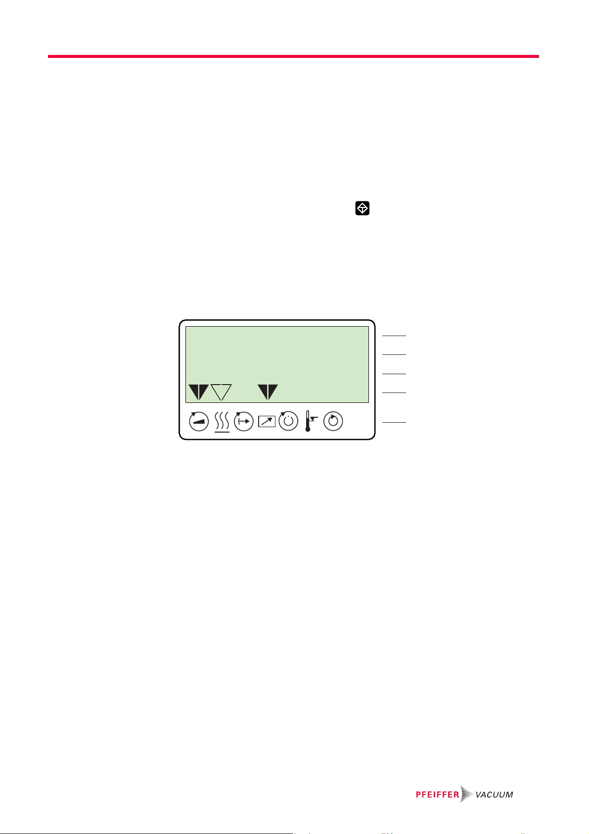
7.2 LC-Display
Operation
721: Venting time
---> 3600 s
795
1
2
3
4
5
The four line LCD visualizes the functions of the TCP.
Functions are assigned as follows:
– Line 1: Number and name of the selected parameter (e.g. 721: Vent time).
– Line 2: relevant value for the selected parameter. The arrow –––► indicates Edit
mode.
– Line 3 with two functions:
– Function 1: Current messages concerning operation and control will be displayed.
– Function 2: presentation of a required second parameter in the format [Parameter
number: value]. The function for this line can be set via parameter [P:795] Servic-
elin in Line 1. All parameters can be accessed with "Servicelin". Error messages
will be displayed independently of the selected function.
– Line 4: presentation of the current equipment status by arrows that point to the asso-
ciated symbols.
– Line 5: Symbols (see below)
25

Operation
7.3 Symbol description
Symbol Description Arrow Explanation
Pump accelerates
= [P:307]
-NO
YES
Preselection heating
= [P:001]
Standby
= [P:002]
Equipment remote controlled
= [P:300]
Switchpoint reached
= [P:302]
Excess temperature - No excess temperatures
Ultimate speed reached
= [P:306]
- No preselection
Preselection heating, switchpoint not attained
Heating On, switchpoint attained
-OFF
ON
-NO
YES
-NO
YES
Excess temperature turbopump = [P:305]
Excess temperature turbo-electronics = [P:304]
Excess temperature turbopump and turbo-electronics
-NO
YES
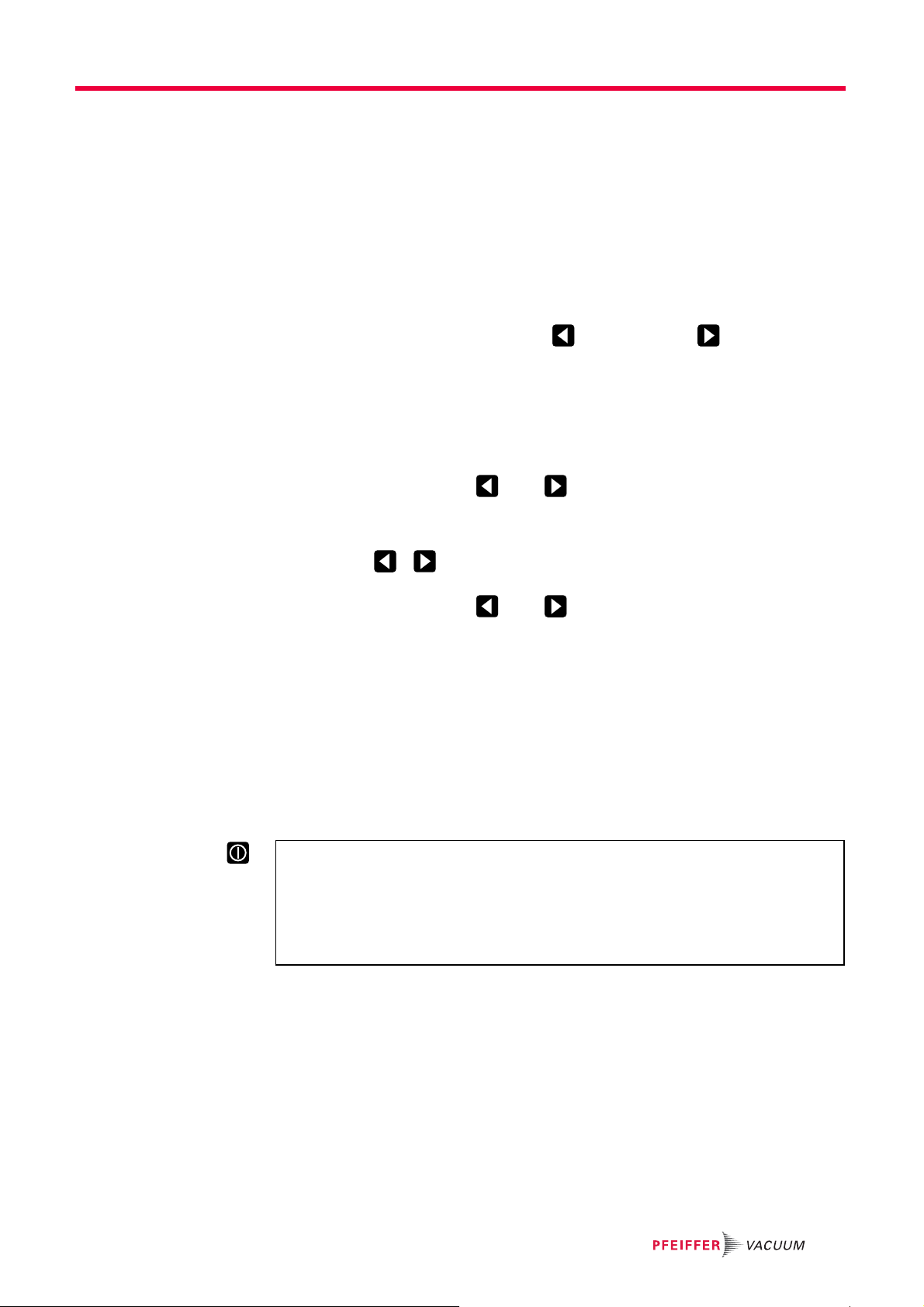
7.4 Key functions
4 short-travel keys (softkeys) constitute the operator interface for the TCP.
Key Application/Example Explanation
Reset (error acknowledgement) acknowledges errors (red
LED illuminates)
[309]: ActualSpd
[308]: SetRotSpd
[310]: DrvCurrent
[311]: OpHrsPump
[001]: Heating
–––► off
Simultaneous
[001]: Heating
on
[010]: PumpgStatn
on / off
Scroll back through parmeters
Scrolls back one parameter
Scroll forwards through parameters
Scrolls forwards one parameter
Change value (Edit mode)
Access to displayed value, if possible
(Arrow–––► is displayed)
Confirm value (Parameter selection mode)
Accept changed value
("change confirmed" is displayed)
Pumping station ON/OFF
switches pumping station on or off.
corresponds to parameter [010]: "PumpgStatn"
26
7.5 Operation
All function-relevant variables of a turbopump are anchored in the electronic drive unit as
parameters. Each parameter has a three-digit number and a designation. Parameters
can be used via Pfeiffer Vacuum display and control units or via RS-485 with the Pfeiffer
Vacuum protocol.
The value of a parameter is always readable. Editable parameters are adjustment commands and target values (See the operating instructions for the respective electronic
drive unit for this purpose).
7.5.1 Selecting the parameters
Preselect parameter number using the (backwards) or (forwards) keys.
– Fast scrolling by pressing and keeping the relevant key depressed.
● The selected parameter appears in line 1, the corresponding value in line 2.
7.5.2 Set parameters
Select a parameter.
Simultaneously press keys and .
● The edit mode for the selected parameter is active.
● At the beginning of the second line an arrow ( –––►) appears.
Operation
Using keys , to decrease or increase the value, respective to change op-
tions.
Simultaneously press keys and .
● If line 3 = empty (see P:795), the following will be displayed: "change confirmed"
● The parameter is set.
● Edit mode for the parameter is ended. The arrow ( –––►) disappears.
Edit mode( –––►) will disappear again automatically under the following conditions and without accepting the value to be changed:
● Input disruption or no key operation for more than 10s.
● If an error occurs.
● Key "Pumping station ON/OFF" has been pressed.
● If line 3 = empty , "data not changed" will be displayed.
Start pump by pressing "Pumping station ON/OFF" key
The "Pumping station" key only controls the parameter [P:010]. All components connected via the electronic drive unit will be activated or deactivated according to their
configuration.
Ensure that the parameter [P:023] is also switched on for powering-up the tur-
bopump.
27

Operation
7.6 Configuring the connections
7.6.1 DO2 and relay on "REMOTE"
Configuration via parameter [P:019] .
● In the description "active" means (trouble-free):
– For DO2: V+ active high
– For relay 2: Active contact change
● Pending errors mean:
– For DO2: low
– For relay 2: inactive
Option Description
0 = mains "OFF" and/or fault
2 = mains "OFF" and/or fault and/or drive OFF
7.6.2 Analog output on "REMOTE"
Configuration via parameter [P:055].
DO2 "low" and relay 2 inactive1 = mains "OFF" and/or fault and/or warning
Option Description
0 = Rotation speed Speed signal; 0 - 10 V DC = 0 - 100 % x f
1 = output: Output signal; 0 - 10 V DC = 0 - 100 % x P
2 = current Current signal; 0 - 10 V DC = 0 - 100 % x I
7.6.3 Accessory connection
Configuration via parameter [P:035] .
Option Description
0 = Heating Control via heating and rotation speed switchpoint reached parameters
1 = TMS Heater* Control via TMS switchbox
2 = fan Control via pumping station parameters
* Only when using pumps with a temperature management system (TMS)
Nominal
max
max
28

Operation with the Pfeiffer Vacuum parameter set
8 Operation with the Pfeiffer Vacuum parameter set
8.1 General
8.1.1 Factory settings
The electronic drive unit is pre-programmed in the factory. This guarantees proper, reliable turbopump operation without the need for additional configuration.
Restore factory settings via parameter [P:095] if necessary.
– Attention! All customized settings will be lost.
8.1.2 Checking the adjustments
Before operating with parameters, check set values and control commands for their
suitability for the pumping process.
Remove the remote plug from electronic drive unit if required.
8.1.3 Keypad lock
The control keys on the front of the electronic drive unit can be locked against unauthorised use.
Locking of the keypad via parameter [P:008].
– All of the keypad input functions are disabled.
– It is still possible to scroll through the parameter list.
The keypad can only be unlocked by:
– Interfaces RS485/RS232
– De-energising through power OFF. The connected pump must run down complete-
ly to idle (f = 0).
8.2 Rotation speed set value
The typical nominal rotation speed of a turbopump is factory-set in the electronic drive
unit. If the electronic drive unit is replaced or a different pump type is used, the reference
set value of the nominal rotation speed must be confirmed. This procedure is part of a
redundant safety system for avoiding excess rotation speeds.
Adjust the parameter [P:777] according to the pump type.
Once the nominal rotation speed is attained, the pump will run idle unless additional gas
loads are entered. Depending on process or application requirements, the nominal rotation speed can be reduced in rotation speed setting mode or standby mode.
Pump type Nominal rotation speed, settings for [P:777] in Hz
CompactTurbo 071 P 1500
CompactTurbo 261/262 P 1000
CompactTurbo 261 P C 833
CompactTurbo 521 P 833
CompactTurbo 521 P C 715
HiPace 60 P 1500
HiPace 80 1500
HiPace 300 1000
HiPace 400 820
HiPace 700 820
HiPace 800 820
29

Operation with the Pfeiffer Vacuum parameter set
8.3 Remote control
There are basically three remote control options with different priorities. The advantage
of the remote control feature is the ability to connect multiple electronic drive units via
"REMOTE".
8.3.1 Standard operation
Standard operation generally means operation via TCP 350 keypad without explicit prioritisation of user interfaces. Beyond this, controls and functions are supported via the
RS-485 interface. Similarly, the switching functions of the "REMOTE" connection are
available if connected.
Parameter [P:028] = 0
● Exception: Connecting pin 14 on REMOTE with +24 V DC assigns priority to the
functions on this connection and locks them for the other interfaces.
8.3.2 REMOTE Priority ON
Connection "REMOTE" on the electronic drive unit has priority over all the functions of
the other interfaces.
Parameter [P:028] = 1
Pin 14 = active High
● Exception: Error acknowledgement is still possible via the corresponding key.
8.3.3 REMOTE Priority OFF
Connection "REMOTE" on the electronic drive unit does not have priority over the functions of the other interfaces.
Parameter [P:028] = 1
Pin 14 = active low
● Exception: Error acknowledgement is not possible via pin 13 until pin 14 "active high"
again.
8.4 Gas type dependent operations
Danger of the pump being destroyed
Pumping of gases with a higher molecular mass in the wrong gas mode can lead to destruction of the pump.
Ensure the gas mode is correctly set.
Contact Pfeiffer Vacuum before using gases with a greater molecular mass (> 80).
Friction causes the rotor to heat up severely under gas load and high rotation speed. To
avoid overheating, the electronic drive unit has implemented power-rotation speed-characteristics, whereby the pump can be operated at every rotation speed with the maximum allowable gas load without danger of damage. The maximum power consumption
depends on the gas type. Three characteristics are available in order to completely exhaust the pump's capacity for each gas type.
NOTICE
30
● Gas mode "0" for gases with the molecular mass >39, e.g. argon.
● Gas mode "1" for gases with the molecular mass 39.
● Power characteristics according to the technical data of the turbopump.
Check and set-up the gas mode via [P:027].

Operation with the Pfeiffer Vacuum parameter set
[P:708]
DB
A
C
Run-up
P
max
Rotation speed
Power
f
N
C-D = Gas mode "0"
A-B = Gas mode "1"
Fig. 7: Principle of power characteristics lines for gas type dependent operations,
e.g. gas mode = 0
The turbopump runs up with maximum power consumption. When the nominal and/or set
rotation speed is reached, the pump automatically switches over to the chosen power
characteristic of the selected gas mode. Increasing gas load is initially compensated by
a rise in power consumption in order to keep the rotation speed constant. Increasing gas
friction, however, causes the turbopump to heat up more severely. When the gastypedependent maximum power is exceeded, the rotation speed of the turbopump is reduced
until an equilibrium between permissible power and gas friction is attained.
To avoid rotation speed fluctuations, Pfeiffer Vacuum recommends setting a some-
what lower frequency in rotation speed setting mode.
8.5 Run-up time
The run-up of the turbopump is time-monitored ex factory. There are various causes of
prolonged run-up times, e.g.:
● Too high gas loads
● Leakage in the system
● The set value run-up time is too low
Eliminate any external and application-related causes.
Adjust the run-up time via parameter [P:700].
8.6 Adjusting the rotation speed switchpoint
The rotation speed switchpoint can be used for the message "Pump operational for the
process". Overrunning or underrunning the active rotation speed switchpoint activates or
deactivates a signal at the pre-configured output on the electronic drive unit and at the
status parameter [P:302].
Adjust the parameter [P:701] to the desired value in %.
Signal output and status parameter [P:302] are based on the set value for rotation speed
switchpoint 1 [P:701].
8.7 Rotation speed setting mode
The rotation speed setting mode reduces the rotation speed and hence the throughput
of the turbopump. The pumping speed of the turbopump changes proportional to rotation
speed. Standby mode is ineffective during rotation speed setting mode. The set rotation
speed is adjusted by the set value in rotation speed setting mode [P:707]. The rotation
speed switchpoint varies with the set rotation speed. Underrunning or overrunning the
set value in rotation speed setting mode activates and deactivates the status signal
[P:306] * respectively.
31

Operation with the Pfeiffer Vacuum parameter set
* Adjust the parameter [P:707] to the desired value in %.
Parameter [P:026] = 1
Query parameters [P:308] .
8.8 Standby
Pfeiffer Vacuum recommends standby mode for the turbopump during process and production stops. When standby mode is active, the electronic drive unit reduces the rotation
speed of the turbopump. Standby mode is ineffective during rotation speed setting mode.
The factory setting for the set value in standby mode is 66.7 % of the nominal rotation
speed. Underrunning or overrunning the set speed in standby mode activates or deactivates the status signal [P:306] *.
* Adjust the parameter [P:717] to the desired value in %.
Parameter [P:026] = 0
Parameter [P:002] = 1
Query parameters [P:308] .
8.9 Operation mode backing pump
Operation of a connected backing pump via the electronic drive unit depends on the
backing pump type.
Connect the control lead of the relay box to the "remote" connection of the electronic
drive unit using an adapter cable.
Adjust the parameter [P:025] to the desired value.
8.9.1 Continous operation
At the same time as "Pumping station on" the electronic drive unit sends a signal to the
pin 11 to switch on the backing pump. This signal can also be used to control a forevacuum safety valve.
8.9.2 Intermittend operation (diaphragm pumps only)
Intermittend operation can extend the life expectancy of the membrane of a connected
diaphragm pump. Either a diaphragm pump with built-in semiconductor relay or an interconnected relay box with semiconductor relay is required for intermittend operation. The
backing pump is switched on and off in dependence of the turbopump's power consumption. A relation to the supplied fore-vacuum pressure is derived from the power consumption. The switching off and switching on thresholds for the backing pump are adjustable.
Fluctuations in the power consumption of idling turbopumps and type-dependent varying
fore-vacuum pressures of the backing pumps require the switching thresholds to be set
separately for the intermittend mode.
Pfeiffer Vacuum recommends the intermittend mode between 5 and 10 hPa. A pressure
gauge and a dosing valve are required to set the switching thresholds.
Switch on the vacuum system via the function "pumping station" and await the run-up.
Generate a fore-vacuum pressure of 10 hPa by gas inlet via dosing valve.
Read and note the parameter [P:316].
Adjust the switch on threshold backing pump via parameter [P:711] to the determined
drive power for a fore-vacuum pressure of 10 hPa.
Reduce the fore-vacuum pressure to 5 hPa.
Read and note the parameter [P:316].
Adjust the switch off threshold backing pump via parameter [P:710] to the determined
drive power for a fore-vacuum pressure of 5 hPa.
32

8.10 Operation with accessories
Depending on the configuration, various accessories can be connected to the turbopump
and controlled via parameter of the electronic drive unit.
Operation with the Pfeiffer Vacuum parameter set
33

Operation with the Pfeiffer Vacuum parameter set
8.10.1 Air cooling/heating
It is necessary to select the accessory device via parameters [P:035].
Display of the selected accessory via parameters [P:335].
If air cooling is connected, it is immediately activated after switching on the pumping station with parameter [P:010].
The ability to operate a connected housing heater depends on the rotation speed switchpoint via parameter [P:701].
Switch heating on or off with parameter [P:001].
Exceeding or dropping below the rotation speed switchpoint controls the operation of the
housing heater. The operating condition is represented by the symbol in the LCD display.
8.10.2 Vent modes
The turbopump can be vented only after the function "pumping station" has been
switched off. Signals are sent to configured outputs with a fixed delay of 6 s. There are
three options for operation with a venting valve connected.
Enable venting via parameter [P:012].
Select the venting mode via parameter [P:030].
Delayed venting
Start and venting time after "pumping station off" are configurable and depend on the rotation speed of the turbopump.
Parameter [P:030] = 0
Adjust the venting rotation speed in % of the nominal rotation speed via parameter
[P:720].
Adjust the venting time in s via parameter [P:721].
If the venting rotation speed is underrun, the venting valve will open for the set venting
time. In the event of a power failure, venting will occur if the set venting rotation speed is
underrun. In this case, the venting period depends on the residual energy delivered by
the moving rotor. When power is restored, the venting process is interrupted.
No venting
No venting is performed during this operation mode.
Parameter [P:030] = 1
Direct venting
Start and venting time are not configurable. Venting starts with a delay of 6 s after "pumping station off". When the function "pumping station" is switched on renewed, the venting
valve closes automatically. In the event of a power failure, venting will occur if an anchored type-specific rotation speed is underrun. When power is restored, the venting
process is interrupted.
34
Parameter [P:030] = 2

8.11 Pressure measurement
Pressure measurement with the TCP
An exact pressure measurement is not possible with the TCP. This is particularly true
with linear gauges in the lower pressure range.
Use suitable measuring instrument.
8.11.1 Displaying the gauge type
Select or enter parameter [P:738] Gaugetype.
Gauges with identical surge impedance are only recognized as a group (e.g. CMR?).
Manual input of the exact gauge type is also possible via the parameter [P:738].
Display example Meaning
TPR 2xx Gauge TPR 280 connected
CMR ? Gauge of the CMR Group connected, exact type not yet set
noGaug No pressure gauge connected
8.11.2 Displaying the active pressure value
Select parameter [P:340] Pressure.
Operation with the Pfeiffer Vacuum parameter set
Display example Meaning
–––––– mbar No pressure gauge connected
< 5E-4mbar Measuring range not reached (dependent on the device)
> 1E3mbar Measuring range exceeded (dependent on the device)
6.3E-9mbar Valid pressure measurement
id fam mbar Gauge type not yet identified; see [P:340]
Error Error in pressure gauge
8.12 Monitoring the thermal load
If threshold values are overrun, output signals from temperature sensors allow the pump
to be brought to a safe condition. Depending on pump type, temperature threshold values for warnings and error messages are saved fixed in the electronic drive unit . For
information purposes, various status queries are prepared in the parameter set.
35

Operation with the Pfeiffer Vacuum parameter set
8.13 Switching on/off the pump
Start pump by pressing "Pumping station ON/OFF" key
The "Pumping station" key only controls the parameter [P:010]. All components connected via the electronic drive unit will be activated or deactivated according to their
configuration.
Ensure that the parameter [P:023] is also switched on for powering-up the tur-
bopump.
8.13.1 Switching on
The function "pumping station" comprises turbopump operation with control of all connected accessories (e.g. backing pump).
Parameter [P:023] = 1
Parameter [P:010] = 1
After successfully completing a self-test, the electronic drive unit switches on the turbopump motor and all connected accessories as per their configuration.
When the pumping station is activated, the motor of the turbopump can be switched off
and on via the function [P:023].
8.13.2 Switching off
Parameter [P:010] = 0
The electronic drive unit switches off the turbopump and activates preset accessory options (e.g. venting ON, backing pump OFF).
36

Pfeiffer Vacuum Protocol for "RS-485"
9 Pfeiffer Vacuum Protocol for "RS-485"
9.1 Telegram frame
The telegram frame of the Pfeiffer Vacuum protocol contains only ASCII code characters
[32; 127], the exception being the end character of the message
(e.g. a PC) sends a telegram, which is answered by a slave (e.g. electronic drive
unit or gauge).
a2 a1 a0 * 0 n2 n1 n0 l1 l0 dn ... d0 c2 c1 c0
a2 - a0 Unit address for slave
– Individual address of the unit ["001";"255"]
– Group address "9xx" for all identical units (no response)
– global address "000" for all units on the bus (no response)
* Action (see p. 37, chap. 9.2)
n2 - n0 Pfeiffer Vacuum parameter numbers
l1 - l0 Data length dn ... d0
dn - d0 Data in data type concerned (see p. 38, chap. 9.3)
c2 - c0 Checksum (sum of ASCII values of cells a2 to d0) modulo 256
C
R
carriage return (ASCII 13)
C
. Basically, a master
R
C
R
9.2 Telegrams
a2 a1 a0 1 0 n2 n1 n0 0 6 N O _ D E F c2 c1 c0
9.2.1 Example 1
Data request ?
a2 a1 a0 0 0 n2 n1 n0 0 2 = ? c2 c1 c0
C
Control command !
a2 a1 a0 1 0 n2 n1 n0 l1 l0 dn ... d0 c2 c1 c0
C
Data response / control command understood
a2 a1 a0 1 0 n2 n1 n0 l1 l0 dn ... d0 c2 c1 c0
C
Error message
C
_RANGE
_LOGI C
NO_DEF The parameter n2 - n0 does not exist
_RANGE Data dn - d0 are outside the permitted range
_LOGIC Logic access violation
Data request
Actual rotation speed (parameter [P:309], device address slave: "123")
? 1230030902=?112
ASCII 49 50 51 48 48 51 48 57 48 50 61 63 49 49 50 13
C
R
R
R
R
R
Data response: 633 Hz
Actual rotation speed (parameter [P:309], device address slave: "123")
1231030906000633037
ASCII 49 50 51 49 48 51 48 57 48 54 48 48 48 54 51 51 48 51 55 13
C
R
37

Pfeiffer Vacuum Protocol for "RS-485"
9.2.2 Example 2
Control command
Switch on pumping station (parameter [P:010], device address slave: "042")
! 0421001006111111020
ASCII 4852504948484948485449494949494948504813
Control command understood
Switch on pumping station (parameter [P:010], device address slave: "042")
! 0421001006111111020
ASCII 4852504948484948485449494949494948504813
9.3 Applied data types
Data type Description Size l1 - l0 Example
0 - boolean_old Boolean value (false / true) 06 000000 / 111111
1 - u_integer Positive integer number 06 000000 to 999999
2 - u_real Positive fixed point number 06 001571 equal to 15.71
4 - string String 06 TC_400
6 - boolean_new Boolean value (false / true) 01 0 / 1
7 - u_short_int Positive integer number 03 000 to 999
10 - u_expo_new Positive exponential number 06 100023
11 - string String 16 BrezelBier&Wurst
C
R
C
R
38

10 Malfunctions
10.1 General
Turbopump and electronic drive unit malfunctions always result in a warning or error
message. In both cases, the electronic drive unit outputs an error code. Operating messages are generally displayed via the LEDs on the electronic drive unit. If an error occurs,
the turbopump and connected devices will be switched off. The selected venting mode
will be triggered after the preset delay.
Automatic start-up after power failure or malfunction acknowledgement
The function "pumping station" of the electronic drive unit remains active after power
failure or errors that lead to shut down the pump or the system. The turbopump runs up
automatically after power ist restored or malfunction acknowledgement.
Switch off the function "pumping station" if necessary.
Provide safety measures against interference in the high vacuum flange while the tur-
bopump is running.
10.2 Operation display via LED
Malfunctions
WARNING
10.2.1 Operation display via LED
The red LED (error status) and green LED (operating status) on the front panel of the
TCP show the following states:
LED Symbol LED status Display Meaning
Green Off currentless
Red Off no malfunction, no warning
10.3 Error codes
Errors (** Error –––– **) always cause the connected peripheral devices to be switched
off.
Eliminate error and reset by pressing key .
Warnings (* Warning –––– *) are only displayed and do not cause components to be
switched off.
On, flashing "Pumping Station OFF", rotation speed ≤ 60 min
On, invers flashing "Pumping Station ON", set rotation speed not at-
tained
On, constantly "Pumping Station ON", set rotation speed at-
tained
On, blinking "Pumping Station OFF", rotation speed > 60 min
On, flashing Warning
On, constantly Malfunction
-1
-1
Error
code
Err001 Excess rotation speed Contact Pfeiffer Vacuum Service
Err002 Overvoltage – Incorrect mains input voltage Check mains input voltage
Err006 Run-up time error – Run-up time threshold set too low
Problem Possible causes Remedy
Only acknowledge for rotation speed f = 0
Only acknowledge for rotation speed f = 0
Contact Pfeiffer Vacuum Service
– Gas flow in vacuum chamber through
leaks or open valves
– Still below rotation speed switchpoint
run-up time expires
Adjust run-up time to process conditions
Check vacuum chamber for leaks and
closed valves
Check backup vacuum connection
Adjust rotation speed switchpoint
39

Accessories
Error
Problem Possible causes Remedy
code
Err007 Operating fluid low – Operating fluid low Check operating fluid
Err015 Group error message control unit Mains OFF/ON at rotation speed f = 0
Err021 Electronic drive unit fails to identify pump – Incorrect characteristic resistance
Err037 Motor final stage or control error Contact Pfeiffer Vacuum Service
Err040 Memory expansion error Contact Pfeiffer Vacuum Service
Err043 Internal configuration error – Parameter values stored incorrectly Contact Pfeiffer Vacuum Service
Err044 Excess temperature electronics – Insufficient cooling Improve cooling
Err045 Motor temperature protection – Motor overheated
Err098 Internal communication error Contact Pfeiffer Vacuum Service
Err621 Electronic drive unit fails to identify pump – Incorrect characteristic resistance
Err699 Error in TCP drive Contact Pfeiffer Vacuum Service
Err777 Nominal speed not confirmed – Nominal speed not confirmed after re-
Wrn007 Undervoltage/mains failure – Mains failure Check power supply
Wrn046 Data channel error – Communication to parameter value
Wrn110 Gauge warning – Gauge faulty
– Pump not connected
– Run-up time in lower speed range (up
to 90 Hz) > 6 min
– Pump not connected
placing electronic drive unit
memory faulty
– Supply cable worked loose during op-
eration
Only acknowledge for rotation speed f = 0
Can be acknowledged a max. of 5 times
Contact Pfeiffer Vacuum Service
Contact Pfeiffer Vacuum Service
Check connections
Contact Pfeiffer Vacuum Service
Only acknowledge for rotation speed f = 0
Check deployment conditions
Improve cooling
Check fore-vacuum connection
– Perform leak detection
– Reduce fore-vacuum pressure
Check connections
Contact Pfeiffer Vacuum Service
Only acknowledge for rotation speed f = 0
Confirm nominal speed with [P:777]
Only acknowledge for rotation speed f = 0
Contact Pfeiffer Vacuum Service
Restart with gauge connected
Replace gauge
Install gauge correctly
11 Accessories
Designation TCP 350 electronic drive unit
Mains cable 230 V AC, CEE 7/7 to C13, 3 m P 4564 309 ZA
Mains cable 115 V AC, NEMA 5-15 to C13, 3 m P 4564 309 ZE
Mains cable 208 V AC, NEMA 6-15 to C13, 3 m P 4564 309 ZF
Adapter cable, TCP 350 - backing pump relay box, M8 PM 061 376 -T
Adapter cable, TCP 350 - backing pump relay box, M12 PM 061 377 -T
Connection cable from TCP 350 to HiPace with 2 accessory ports M8,
3 m
Connection cable from TCP 350 to HiPace with 2 accessory ports
M12, 3 m
PM 061 353 -T
PM 061 356 -T
40

12 Technical data and dimensions
12.1 Technical data
Parameter TCP 350
Ambient temperature 5-40 °C
Protection category IP 20
Mains requirement: power consumption 420 VA
Mains requirement: voltage (range) 95-265 V AC
Frequency 50/60 Hz
Weight 2.8 kg
Cable length Turbo-TCP max. 110 m
Interface RS-485
12.2 Dimensions
142 (28TE)
127
Technical data and dimensions
232.4
128.5 (3HE)
111
122.5
242.4
41

Declaration of conformity
We hereby declare that the product cited below satisfies all relevant provisions according to the following EC directives:
● Electromagnetic Compatibility 2014/30/EU
● Low Voltage 2014/35/EU
TCP 350
Harmonised standards and national standards and specifications which have been applied:
DIN EN 61000-3-2 : 2010
DIN EN 61000-3-3 : 2009
DIN EN 61010-1 : 2010
DIN EN 61326-1 : 2013
DIN EN 62061 : 2013
Semi F47-0200
Semi S2-0706
Signature:
(Dr. Ulrich von Hülsen)
Managing Director
Pfeiffer Vacuum GmbH
Berliner Straße 43
35614 Asslar
Germany
2017-03-31

VACUUM SOLUTIONS FROM A SINGLE SOURCE
Pfeiffer Vacuum stands for innovative and custom vacuum solutions worldwide,
technological perfection, competent advice and reliable service.
COMPLETE RANGE OF PRODUCTS
From a single component to complex systems:
We are the only supplier of vacuum technology that provides a complete product portfolio.
COMPETENCE IN THEORY AND PRACTICE
Benefit from our know-how and our portfolio of training opportunities!
We support you with your plant layout and provide first-class on-site service worldwide.
Are you looking for a
perfect vacuum solution?
Please contact us:
www.pfeiffer-vacuum.com
Pfeiffer Vacuum GmbH
Headquarters • Germany
T +49 6441 802-0
info@pfeiffer-vacuum.de
 Loading...