

Pfeiffer Vacuum Penta Series, Penta 10, Penta 20, Penta 35 Translation Of The Original Operating Instructions

Betriebsanleitung • Operating Instructions
(505)872-0037
idealvac.com
idealvac.com
Translation of the Original Operating Instructions
PD 0033 BE/B (0811)
Rotary Vane Pump
Penta 10/20/35

Table of contents
Table of contents
1 About this manual . . . . . . . . . . . . . . . . . . . . . . . . . . . . . . . . . . . . . . 3
1.1 Validity . . . . . . . . . . . . . . . . . . . . . . . . . . . . . . . . . . . . . . . . . . . . . . . . 3
1.2 Conventions . . . . . . . . . . . . . . . . . . . . . . . . . . . . . . . . . . . . . . . . . . . 3
2 Saf e ty . . . . . . . . . . . . . . . . . . . . . . . . . . . . . . . . . . . . . . . . . . . . . . . . 5
2.1 Safe ty precautions . . . . . . . . . . . . . . . . . . . . . . . . . . . . . . . . . . . . . . 5
2.2 Proper use. . . . . . . . . . . . . . . . . . . . . . . . . . . . . . . . . . . . . . . . . . . . . 5
2.3 Improper use . . . . . . . . . . . . . . . . . . . . . . . . . . . . . . . . . . . . . . . . . . . 5
3 Tr a ns port and s torage . . . . . . . . . . . . . . . . . . . . . . . . . . . . . . . . . . 6
3.1 Transport. . . . . . . . . . . . . . . . . . . . . . . . . . . . . . . . . . . . . . . . . . . . . . 6
3.2 Storage . . . . . . . . . . . . . . . . . . . . . . . . . . . . . . . . . . . . . . . . . . . . . . . 6
4 Pro duct des c ription . . . . . . . . . . . . . . . . . . . . . . . . . . . . . . . . . . . . 7
4.1 Product identification. . . . . . . . . . . . . . . . . . . . . . . . . . . . . . . . . . . . . 7
4.2 Function . . . . . . . . . . . . . . . . . . . . . . . . . . . . . . . . . . . . . . . . . . . . . . 8
5 Installation . . . . . . . . . . . . . . . . . . . . . . . . . . . . . . . . . . . . . . . . . . . . 9
5.1 Setti ng up the pu mp . . . . . . . . . . . . . . . . . . . . . . . . . . . . . . . . . . . . . 9
5.2 Connecting th e v a cuum side. . . . . . . . . . . . . . . . . . . . . . . . . . . . . . . 9
5.3 Connectin g the exhaust side. . . . . . . . . . . . . . . . . . . . . . . . . . . . . . 1 0
5.4 Connecting to the mains power supply . . . . . . . . . . . . . . . . . . . . . . 10
5.5 Make remote connec tion. . . . . . . . . . . . . . . . . . . . . . . . . . . . . . . . . 13
5.6 Filling up the operating fluid . . . . . . . . . . . . . . . . . . . . . . . . . . . . . . 14
5.7 Operations mo n itoring (Option). . . . . . . . . . . . . . . . . . . . . . . . . . . . 15
5.8 Fitting the ONF and the oil return line (option) . . . . . . . . . . . . . . . . 15
6 Operation. . . . . . . . . . . . . . . . . . . . . . . . . . . . . . . . . . . . . . . . . . . . 16
6.1 Before switching on the pump. . . . . . . . . . . . . . . . . . . . . . . . . . . . . 1 6
6.2 Swit c h i n g o n th e pump . . . . . . . . . . . . . . . . . . . . . . . . . . . . . . . . . . 16
6.3 Pumping conden sa ble vapours. . . . . . . . . . . . . . . . . . . . . . . . . . . . 17
6.4 Switching off . . . . . . . . . . . . . . . . . . . . . . . . . . . . . . . . . . . . . . . . . . 18
7 Maintenance. . . . . . . . . . . . . . . . . . . . . . . . . . . . . . . . . . . . . . . . . . 19
7.1 Precautions . . . . . . . . . . . . . . . . . . . . . . . . . . . . . . . . . . . . . . . . . . . 19
7.2 Changing the o pe rating fluid. . . . . . . . . . . . . . . . . . . . . . . . . . . . . . 20
8 Dec ommiss ioning . . . . . . . . . . . . . . . . . . . . . . . . . . . . . . . . . . . . . 22
8.1 Shutting down for longer periods. . . . . . . . . . . . . . . . . . . . . . . . . . . 2 2
8.2 Re-starting. . . . . . . . . . . . . . . . . . . . . . . . . . . . . . . . . . . . . . . . . . . . 22
8.3 Disposal . . . . . . . . . . . . . . . . . . . . . . . . . . . . . . . . . . . . . . . . . . . . . 22
9 Malfunctions . . . . . . . . . . . . . . . . . . . . . . . . . . . . . . . . . . . . . . . . . 2 2
9.1 Rectifying malfunctions. . . . . . . . . . . . . . . . . . . . . . . . . . . . . . . . . . 23
10 Service . . . . . . . . . . . . . . . . . . . . . . . . . . . . . . . . . . . . . . . . . . . . . . 25
11 Spare parts . . . . . . . . . . . . . . . . . . . . . . . . . . . . . . . . . . . . . . . . . . 26
12 Accessories. . . . . . . . . . . . . . . . . . . . . . . . . . . . . . . . . . . . . . . . . . 2 7
13 T e c h nical data . . . . . . . . . . . . . . . . . . . . . . . . . . . . . . . . . . . . . . . . 2 8
13.1 Dimensions . . . . . . . . . . . . . . . . . . . . . . . . . . . . . . . . . . . . . . . . . . . 2 9
Declaration of conformity . . . . . . . . . . . . . . . . . . . . . . . . . . . . . . 3 0
2

1 About this manual
1.1 Validity
This operating manual is for customers of Pfeiffer Vacuum. It describes the functioning of the designated product and provides the most important information for
safe use of the unit. The description follows applicable EU guidelines. All information provided in this operating manual refer to the current state of the product's development. The documentation remains valid as long as the customer does not
make any changes to the product.
Up-to-date operating instructions can also be downloaded from
www.pfeiffer-vacuum.net.
Applicable documents
Penta 10/20/35 Operating instructions
Safety information for vacuum pumps "Safety Guide" PT 0300 BN*
Declaration of Conformity Part of this document
Operating instructions for accessories (order-specifically) see section "accessories"*
*also available via www.pfeiffer-vacuum.net
About this manual
1.2 Conventions
Safety instructions The safety instructions in Pfeiffer Vacuum operating manuals are the result of risk
evaluations and hazard analyses and are oriented on international certification
standards as specified by UL, CSA, ANSI Z-535, Semi-S1, ISO 3864 and DIN 4844.
In this document, the following hazard levels and information are considered:
DANGER
Immediate danger
Death or very severe injuries occur.
WARN ING
Possible danger
Death or injuries may occur.
CAUTION
Possible danger
Medium to slight injuries may occur.
NOTE
Command or note
Command to perform an action or information about properties, the disregarding of
which may result in damage to the product.
3
About this manual
V
G
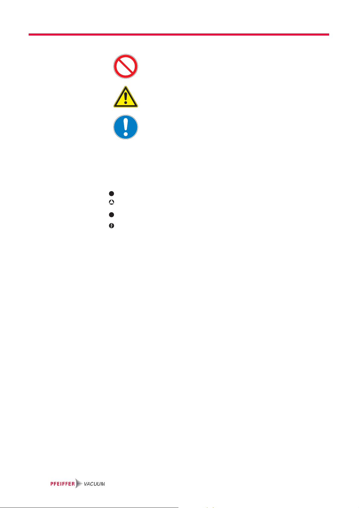
Pictograph
definitions
Instructions in the
Work instruction: here you have to do something.
Prohibition of an action or activity in connection with a
source of danger, the disregarding of which may result in
serious accidents.
Warning of a displayed source of danger in connection
with operation of the unit or equipment.
Command to perform an action or task associated with a
source of danger, the disregarding of which may result in
serious accidents.
text
Symbols used The following symbols are used consistently throughout in all illustrations:
Vacuum flange
Exhaust flange
Gas ballast valve
Power connection
4

2Safety
2.1 Safety precautions
Duty to inform
Each person involved in the installation, operation or maintenance of the vacuum
pump must read and observe the safety-related parts of these operating instructions.
Absolute observe the safety information for vacuum pumps (PT 0300 BN) !
The operator is obligated to make operating personnel aware of dangers originating
from the vacuum pump, the pumped medium and the entire system.
• Do not expose any body parts to the vacuum.
• Observe the safety and accident prevention regulations.
• Check regularly that all safety precautions are being complied with.
• Do not carry out any unauthorised modifications or conversions to the pumps.
• Depending on the operating and ambient conditions, the surface temperature of
the pumps may rise above 70 °C. Use suitable finger guards if necessary.
• When returning the pumps to us please note the instructions in the Service section.
Safety
NOTE
2.2 Proper use
2.3 Improper use
NOTE
CE conformity
The manufacturer's declaration of conformity becomes invalid if the operator modifies
the original product or installs additional components.
Following installation into a plant and before commissioning, the operator must
check the entire system for compliance with the valid EU directives and reassess it
accordingly.
• The vacuum pump may only be used to generate a vacuum.
• Installation, operating and maintenance regulations must be complied with.
• Other accessories than those described in this manual must not be used without
the agreement of Pfeiffer Vacuum.
Improper use will cause all claims for liability and guarantees to be forfeited. Improper use is deemed to be all use for purposes deviating from those mentioned
above, especially:
• Pumping of corrosive gases.
• Pumping of explosive media.
• Operation of the pump in potentially explosive areas.
• Pumping of gases containing impurities such as particles, dusts and condensate;
note the vapour compatibility levels of the pump.
• Pumping of substances that tend to sublime.
• Use of the vacuum pump to generate pressure.
• Pumping of liquids.
• The use of operating fluids not specified by Pfeiffer Vacuum.
• Connection to pumps or units which are not suitable for this purpose according
to their operating instructions.
• Connection to units which have exposed voltage-carrying parts.
5

Transport and storage
• The operation of the devices in potentially radioactive areas.
3 Transport and storage
3.1 Transport
Remove the locking cap from the vacuum and exhaust flange immediately be-
fore connecting!
– Check the cone strainer, paying attention to the o-ring.
Use only the eye bolt on the top side of the pump to lift the pump.
3.2 Storage
Fig. 1: Transporting the pump
Check that all the openings on the pump are securely closed.
Store the pump in a cool, dry place; preferably at room temperature (approx.
20°C).
– For a longer period of storage, seal the pump in a PE bag with drying agents
enclosed.
– For a period of storage longer than one year, it is recommended to carry out
maintenance and change the operating fluid.
6
4 Product description
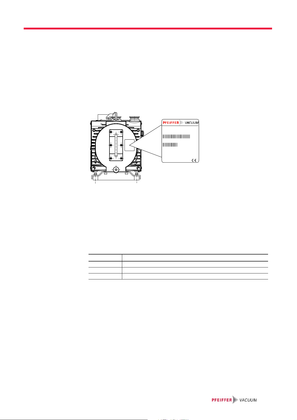
4.1 Product identification
To correctly identify the product when communicating with Pfeiffer Vacuum, always have the information from the rating plate available.
• Pump model and model number
• Serial number
• Type and amount of operating fluid
• Date of manufacture
D-35641 Asslar
Mod.: Penta 20
Mod.-Nr.: PK D74 xxx
Ser.- Nr.: 3454440
S : max. XXX m /h
(N )
2
Oil : P3 X l
Mass : XX kg
n : XXXX 1/min
max.
Made in Germany 2005/01
3
Product description
Fig. 2: Product identification on the rating plate
Scope of delivery • Pump with drive unit
• Operating fluid P3 (for standard pump)
• Cone strainer and centering ring with O-ring
• Locking cap for vacuum and exhaust flange
• Remote plug with bridge (On/Off function)
• Operating instructions
Pump types
Pump type Pumping speed [m3/h]
Penta 10 11
Penta 20 22
Penta 35 34
7

Product description
V
G
172
172a
161
161
2
1
50.1
50.2
32
4
6
4.2 Function
The PentaLine® pumps are two-stage rotary shutter pumps with an electronic drive
concept for all coarse and fine vacuum applications. Since the drive is coupled to
the pump system by a contactless mechanism, it suffers no mechanical wear and
is completely maintenance-free. The pumps are equipped with a vacuum safety
valve that vacuum seals the vacuum chamber and vents the pump at the same time
when the pump is at a standstill.
1 Vacuum flange
2 Exhaust flange
4 Casing panel
6Base
32 Mains connection
50.1 Remote connection
50.2 Remote plug with bridge
161 Gas ballast valve
162 Connection for operating fluid
return line
172 Operating fluid filler screw
172a Operating fluid drain screw
Fig. 3: Penta 10/20/35
8

5 Installation
5.1 Setting up the pump
Installation location When installing the pump, observe the following conditions:
• Note the load-bearing capacity of the mounting surface.
• Maximum installation altitude 1000 m (above mean sea level)
• Permissible ambient temperature: +12 ... 40°C
• Maximum relative humidity 95%
≥ 35 mm
Installation
°
±
max. 10
≥ 5 mm
≥ 5 mm
Fig. 4: Installation
Fill up with operating fluid before operating the first time (see p. 14, chap. ).
– Amount and type according to rating plate
Always place the pump on a firm, even surface.
– Where stationary installation is involved, anchor the pump on site.
When installing the pump in a closed housing, ensure there is sufficient air cir-
culation.
– Sightglass and gas ballast valve must be visible and readily accessible.
– Voltage and frequency information given on the motor rating plate must be
visible.
5.2 Connecting the vacuum side
Remove locking cap from the vacuum flange;
– pay attention to the cone strainer and the respective O-ring in the intake port.
The connection between the pump and the recipient should be kept as short as
possible.
9
Installation
– Depending on the pump type, use metallic hoses or PVC hoses with flange
connections.
– Separators, filters etc. may be installed upstream to protect the pump (see ac-
cessories). However, please observe the loss of pumping capacity due to the
conductivity of the accessories.
5.3 Connecting the exhaust side
High pressure in the exhaust line!
Danger of damage to the seals and danger of the pump bursting.
Install the line without shut-off valves on the exhaust side.
If there is danger of a build-up of excess pressure (> 1500 mbar abs.) in the lines,
observe all official accident prevention safety regulations.
If the exhaust gases are being extracted, the exhaust pressure must be at least
250 mbar greater than the pressure at the intake side.
Choose the cross-section of the exhaust line to be at least the size of the nominal
connection diameter of the vacuum pump's exhaust connection.
Piping to the pump must be suspended or supported.
– Physical forces from the piping system must not be allowed to act on vacuum
pumps.
Lay piping from the pump sloping downward so that no condensate can flow
back into the pump; otherwise fit a condensate separator.
– If an air trap is created in the system, then a device for draining condensation
water must be provided at the lowest point.
CAUTION
Emission of toxic substances from the exhaust!
Danger of poisoning from emitted gases or vapours, which can be detrimental to
health and/or can pollute the environment, depending on the particular application.
Comply with the applicable regulations when working with toxic substances.
Only officially approved filter systems may be used to separate and remove these
substances.
5.4 Connecting to the mains power supply
The input voltage may lie in the ranges 100 ... 120 VAC (50/60 Hz) and 200 ... 240
VAC (50/60 Hz). The pump is preset ex works to a voltage range of 200 ... 240 VAC.
In case of another supply voltage the input has to be switched over accordingly.
Voltage-bearing elements
Danger to life from electric shock.
The electrical connection can be carried out only by trained and authorised electrici-
ans.
Ensure the system is adequately earthed.
WARN ING
DANGER
10

Installation
1
23
4
WARN ING
Safe electrical installation
Safe operation after installation is the responsibility of the operator. The pump and its
electrical equipment have no lock-out/tag-out device and no emergency off device.
Make sure that the system is integrated in an emergency off safety circuit.
– If an emergency off situation is triggered, the voltage supply must be imme-
diately interrupted.
Consult Pfeiffer Vacuum for special requirements.
CAUTION
Excess voltage!
Danger of destroying the motor.
Power connections must comply with local regulations. Voltage and frequency infor-
mation given on the motor rating plate must correspond to the mains voltage and
frequency values.
To protect the motor and supply cable in case of malfunction, mains fuse protection
must be implemented.
Connecting to the
mains power supply
Permissible input voltage range:
• 100 ... 120 VAC ( ± 10 %)
• 200 ... 240 VAC ( ± 10 %)
1 Neutral conductor
2 Phase L1
3 not connected
4earth, PE
Fig. 5: Power supply pin assignment; Type: Harting Han 3A
The drive electronics ensures automatically the correct direction of rotation of the
pump.
Fuse protection
To protect the motor in case of malfunction, carry out fuse protection in accor-
dance with the regional regulations.
– Select a fuse with slow characteristics.
11

Installation
L1
N
PE
02 04 01
F 1
240
240
120
S
Fig. 6: Example for fuse protection for single phase operation
max. current: 17.7 A
Changing the voltage
range
The mains voltage must be determined on-site each time before the pump is in-
stalled or moved to a different location.
NOTE
Overvoltage!
An incorrect voltage range setting can damage the motor.
Disconnect the pump from the power supply.
Only change the voltage range when the pump is disconnected from the power
mains.
A voltage selector switch below the connector plate enables toggling between the
two voltage ranges. The factory default setting is 200 ... 240 VAC.
S Voltage selector switch
12
Fig. 7: Changing the voltage range for the power supply
Disconnect the pump from the power supply.

Installation
1
2 (+24 V)
1
3
4
2
34
Remove the connector plate and set the voltage selector switch "S" to the desi-
red voltage range.
Monitoring of the
operation conditions
The pump features the following functions for monitoring the pump components:
• Monitoring the temperature of the electronics
– Resetting by briefly removing the remote connector or by disconnecting from
the mains ("Off/On").
• Monitoring the internal motor winding temperature
– Resetting by briefly removing the remote connector or by disconnecting from
the mains ("Off/On"), followed by pump cooling.
• Surge current shut-down of electronics
– Resetting by briefly removing the remote connector or by disconnecting from
the mains ("Off/On").
5.5 Make remote connection
Fig. 8: Remote connector pin assignment M12 socket, 4-pin (A-coded)
2+ 24 V*
2-1 Pump "On"
2-3 Temperature control mode "On"
2-4 Standby "On"
13
Installation
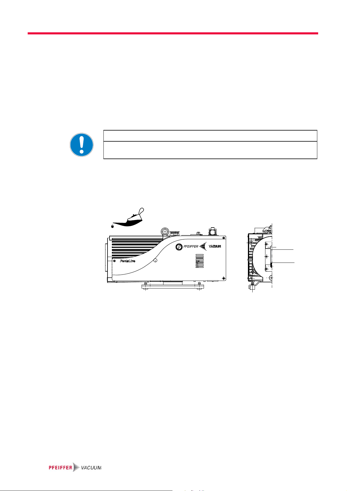
5.6 Filling up the operating fluid
The type and amount of operating fluid should be visible on the pump's rating
plate for every rotary vane pump.
The delivery consignment for the standard pump contains sufficient operating
fluid for one filling. The use of other operating fluids requires prior authorisation
from Pfeiffer Vacuum.
Permissible operating fluid
• P3 (standard operating fluid)
• Operating fluid for special applications on request
Guarantees relating to attainment of final pressures and trouble free functioning
of the pump apply only providing a permissible operating fluid is used.
NOTE
Filling up the operating fluid
Unscrew operating fluid filler screw 172.
Fill up operating fluid.
– Correct filling level during operations: Within the markings at the sightglass
frame.
max.
min.
Fig. 9: Filling up the operating fluid
Screw in operating fluid filler screw 172.
Check operating fluid level only when the pump is warm and running; close
– vacuum flange and gas ballast valve to do so,
– Check operating fluid daily in non-stop operation, otherwise whenever the
pump is switched on. Refilling is possible when the pump is in final vacuum
operation.
14
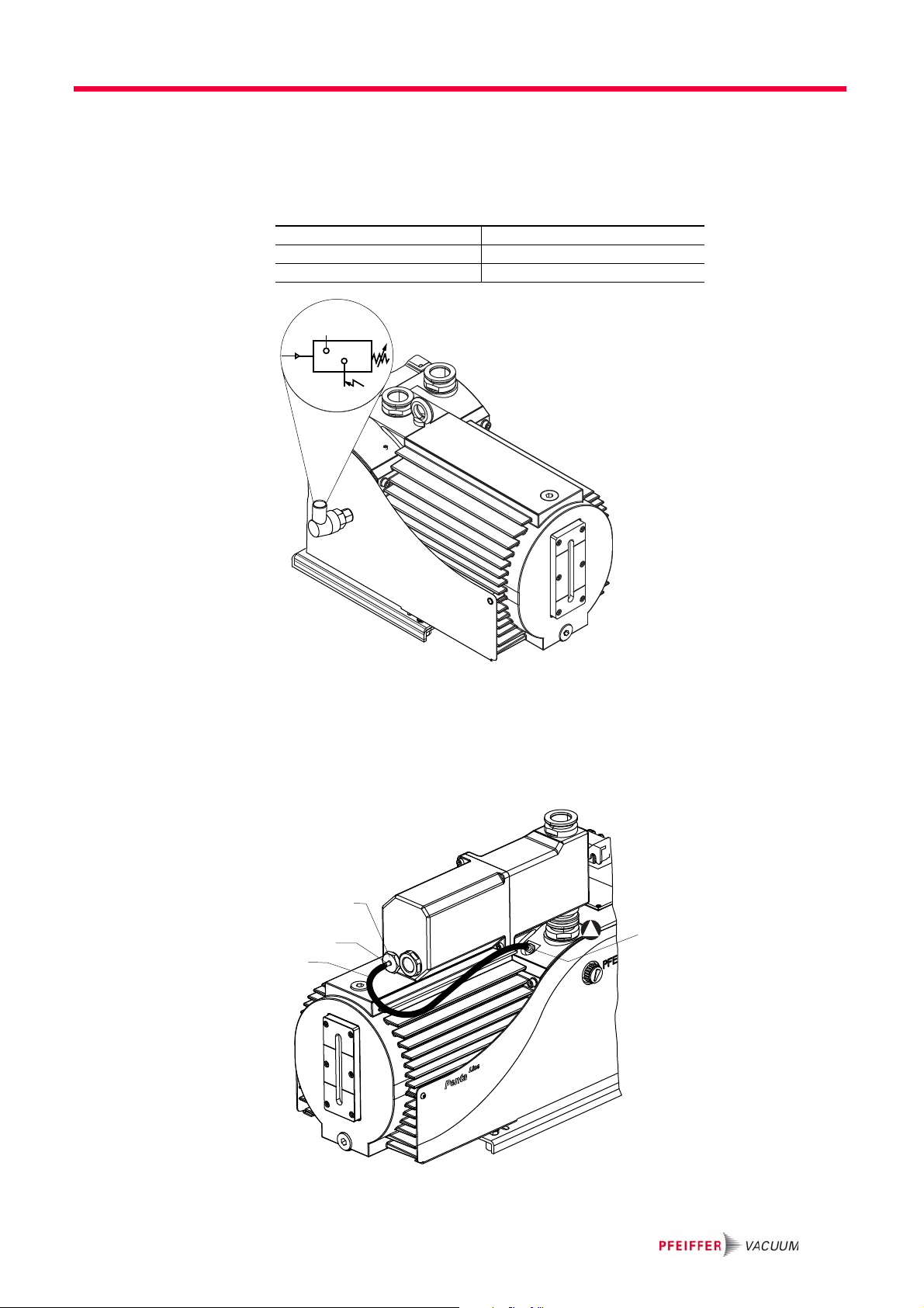
5.7 Operations monitoring (Option)
1
2
A pressure switch can be installed on the side of the support to monitor the operating fluid pressure of the rotary vane pump during operations. By pressure drop
and when the pump is at rest, the contact of the pressure switch opens. The signal
can be used to control external valves.
Switching voltage: 5 ... 250 Volt (potential-free)
Current, max. 2 Amp.
Protection class IP 55
Installation
1 + 2 closers = pressureless open
Fig. 10: Pressure switch; installation location and circuit diagram
5.8 Fitting the ONF and the oil return line (option)
For frequent pumping at higher intake pressures the use of an oil mist filter with
oil return line is recommended in order to reduce the discharge of oil mist.
33
(241/145)
243
242
77
(78)
Fig. 11: Penta 35 with oil mist filter ONF 25 XL
15
Operation
Position the ONF on the small flange on the exhaust side of the pump and fit
using the tension ring (accessory); take care with the centering ring.
Screw in hose nipple 241 inplace of the operating fluid drain screw.
Fit operating fluid return hose 242 at both sides on the hose nipples and tighten
with hose clip at the ONF side.
6 Operation
6.1 Before switching on the pump
Check the operating fluid level in the sightglass.
Compare the voltage and frequency information on the rating plate with the
mains voltage and frequency values.
Check that the exhaust connection allows free flow (max. permissible pressure
1.5 bar absolute).
– Activate the shut-off valves in such a way that they open before or at the same
time as the pump is started.
Protect the pump sufficiently from taking in contaminants by means of suitable
precautions (e.g. dust filters); if necessary, check operating fluid regularly or replace at shorter intervals.
6.2 Switching on the pump
The pump can be switched on in any pressure range.
No special precautions are necessary when pumping dry gases. In order to attain
the lowest possible final pressures, the gas ballast valve should be closed.
CAUTION
Hot surface!
Danger of burns if hot parts are touched. Depending on the operating and ambient
conditions, the surface temperature of the pump may rise above 70 °C.
In this case, use suitable finger guards.
Switch-on pump via remote plug with bridge 50.2.
Standby The pump can be operated with reduced rotation speed (standby) during process
breaks or in cases with small load. Thus the power consumtion of the pump is reduced and the operating temperature of the pump lowered.
Bridge Pin 2 and Pin 4 at remote connection 50.1 (see p. 13, chap. 5.5);
– use customized remote plug (see p. 27, chap. 12).
NOTE
Improper operating status of the pump!
Simultaneously standby and temperature control mode leads to an increased operating temperature and therefore to switching off the pump.
In addition, do not use gas ballast while the pump is on standby.
16
6.3 Pumping condensable vapours
161
Should the process gases contain condensable gases present at high percentages,
the rotary vane pump must be operated with a gas ballast (i.e. with an open gas
ballast valve).
Bad final vacuum and damage to the pump!
Danger of condensation and corrosion due to exceeding the water vapour compatibility (see Technical data) during operation without a gas ballast or in case of insufficient
supply of flushing gas.
Only pump vapours when the pump is warm and the gas ballast valve is open.
When the process has been completed, allow the pump to continue running for
about 30 minutes with the vacuum flange closed and the gas ballast open for operating fluid regeneration purposes.
Operation
CAUTION
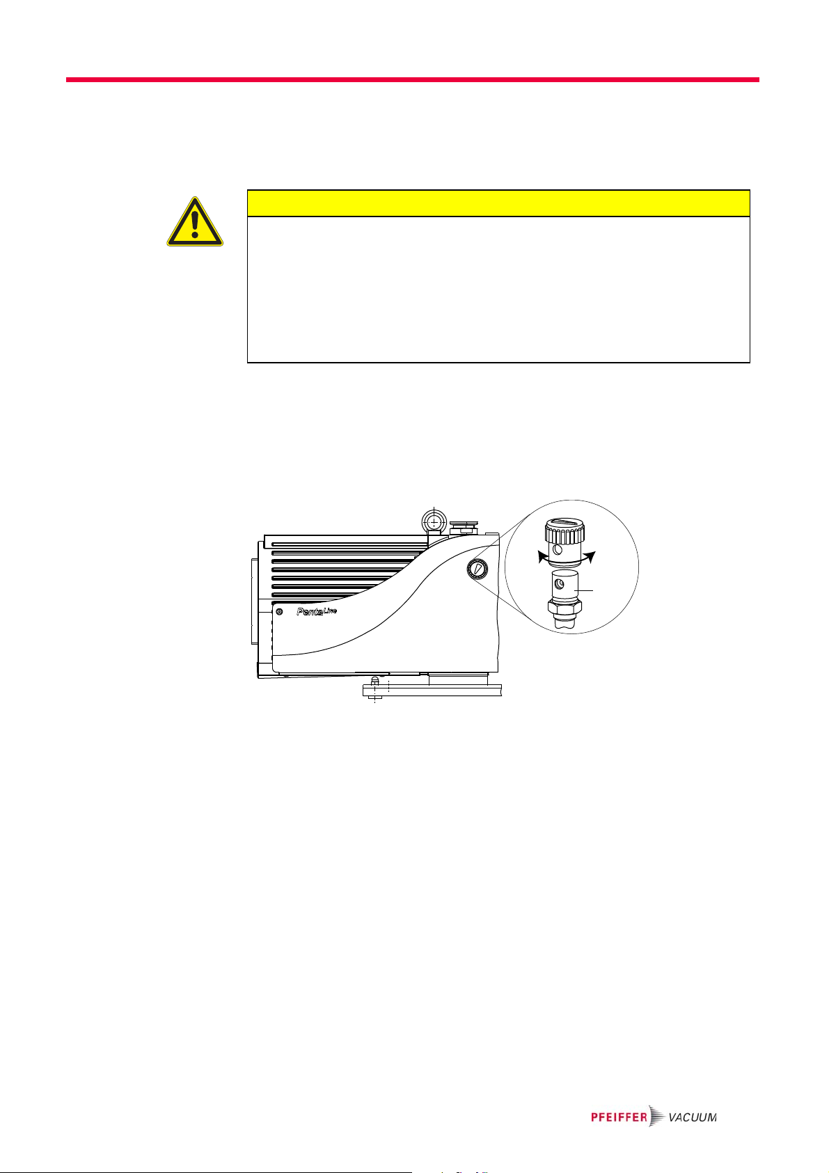
Gas ballast valve,
standard version
Temperature control
mode
To avoid condensation in the pump when pumping condensable vapours, air is periodically fed into the working chamber at the beginning of the compression phase
via the gas ballast valve 161.
Open gas ballast valve; to do so, turn cap 43 on the gas ballast valve 161 so that
the two holes line up.
Fig. 12: Operation with gas ballast valve 161
Operating the pump in temperature control mode will further improve the discharge of liquids when pumping large volumes of condensable vapours. The fan
is temporarily switched off to increase the operating temperature of the pump.
Open gas ballast valve; to do so, turn cap 43 on the gas ballast valve 161 so that
the two holes line up.
Bridge Pin 2 and Pin 3 at remote connection 50.1 to switch on the temperature
control mode;
– use customized remote plug (see p. 27, chap. 12).
17
Operation
6.4 Switching off
Venting the vacuum
chamber
Maintaining the vacuum in the chamber
The pump can be switched off in any pressure range.
Rotary vane pumps have an integrated safety valve on the intake side. If the differential pressure between the exhaust side and the intake side is ≥ 250 mbar, then
the valve closes automatically and vents the pump when the pump is switched off.
Switch-off pump by disconnecting from mains or via remote bypass50.2.
CAUTION
Danger of backflow of operating fluid into the intake line!
Contamination of the connected vacuum system!
Vent the vacuum chamber within 30 s, regardless of the chamber size.
For a longer venting process, use an additional shut-off valve and shut off the intake
line after switching off the pump.
CAUTION
Danger of backflow of operating fluid into the intake line!
Contamination of the connected vacuum system!
Because the safety valve of the pump is not suitable for longer-term sealing, install
an additional shut-off valve in the intake line.
Shut off the intake line immediately after switching off the pump.
18

7 Maintenance
7.1 Precautions
Pump parts may be contaminated from pumped media!
Danger of poisoning due to contact with harmful substances.
Decontaminate the pump before carrying out any maintenance work.
In the event of contamination, take suitable safety precautions to prevent your health
Switch off the pump, vent it to atmospheric pressure and let it cool down.
Disconnect the drive motor from the mains and secure it so that it cannot be
Only dismantle the pump as far as necessary in order to repair defects.
Dispose of used operating fluid in compliance with local regulations.
When using synthetic operating fluids or working with toxic substances or sub-
Use only alcohol or similar agents for cleaning pump parts.
Maintenance
WARNING
from being harmed by any dangerous substances.
switched on.
stances contaminated with corrosive gases, the relevant instructions governing
their use must be observed.
Checklist for inspection, maintenance
and overhaul
Certain repair and overhaul work should only be performed by Pfeiffer Vacuum
Service (PV). Pfeiffer Vacuum will be released from all warranty and liability claims
if the required intervals for inspection, maintenance, or overhaul are exceeded or
inspection, maintenance, repair or overhaul procedures are not performed properly. This also applies if replacement parts other than Pfeiffer Vacuum OEM replacement parts are used.
Activity daily as required;
at least
annually
Check operating fluid level X
Visual inspection (leak-tightness/oil
leaks)
Check filter insert of external oil mist filter
(if existent)
Change filter insert of external oil mist filter (if existent)
Change operating fluid X
Cleaning the pump and renew the seals X
Clean gas ballast valve and silencer
nozzle
Clean the fan intake side X
Clean or change vacuum safety valve X (PV)
Clean or change exhaust valves X (PV)
Change vanes and hydraulic vane X (PV)
Depending on the process, the required replacement intervals for lubricants and the intervals for
inspection, maintenance and overhaul may be shorter than the guide values specified in the table.
Consult with Pfeiffer Vacuum Service if necessary.
X
X
X
X
as required;
at least
every 2
years
as required;
at least
every 4
years
19

Maintenance
172a
7.2 Changing the operating fluid
The changing interval for the operating fluid depends on the pump applications,
but should be carried out once a year.
Depending on the applications, Pfeiffer Vacuum recommends determining the
exact service life of the operating fluid during the first year of operation.
The replacement interval may vary from the guide value specified by Pfeiffer Vacuum
depending on the thermal and chemical loads, and the accumulation of suspended particles and condensation in the operating fluid.
Hot operating fluid!
Danger of burns when draining due to contact with skin.
Wear suitable protective clothing.
Use a suitable collecting vessel.
Switch off pump.
Unscrew operating fluid drain screw 172a and drain operating fluid.
Fill the specimen in a test tube or some similar vessel and test by holding
against the light.
The level of deterioration of operating fluid P3 can be read off the colour scale
in accordance with DIN 51578; request the supplementary sheet PK 0219 BN or
download it from the Internet.
Where discolouration is dark yellow to red brown (equivalent to 4 ... 5 on the sca-
le) change operating fluid.
NOTE
WARN ING
20
Fig. 13: Draining the operating fluid

WARNING
Operating fluid may contain toxic substances from the pumped media!
Danger of poisoning from the emission of harmful substances from the operating fluid.
Wear suitable protective clothing and respirators.
Dispose of operating fluid according to the local regulations
Screw in operating fluid drain screw 172a; pay attention to o-ring.
Allow pump to run for a maximum of 5 seconds with the vacuum flange open.
Drain off remaining operating fluid.
– In case of serious contamination, the operating fluid will have to be changed
several times (flushing):
Flushing Fill up with operating fluid to the middle of the sight glass.
Operate the pump with the gas ballast open until the pump has warmed up.
Drain the operating fluid again and check for contamination, flush again if neces-
sary.
Screw the operating fluid drain screw back in.
Fill up with operating fluid and check the filling level (siehe S. 14, Kap. ).
Maintenance
NOTE
Request safety data sheets for operating fluids and lubricants
from Pfeiffer Vacuum or download them from the Internet.
Dispose of operating fluid according to the local regulations.
21

Decommissioning
8 Decommissioning
8.1 Shutting down for longer periods
Before shutting down the pump, observe the following procedure and adequately
protect the pump system against corrosion:
Switch off pump.
Change operating fluid(see p. 20, chap. 7.2).
Start the pump and allow the pump to warm up.
Fill up the pump with new operating fluid to the top edge of the sightglass.
Close vacuum flange and exhaust flange with locking caps.
8.2 Re-starting
Visually inspect the inner of the pump before taking it into operation. If there is evidence of rust on the parts of the pump which form the housing, then do not take
it into operation and contact Pfeiffer Vacuum Service.
In accordance with DIN 7716 and the manufacturer's specifications we recommend
replacing the installed elastomer parts after 2 years.
If drying pearls were inserted then they should be removed now. Improper
handling can cause failure of the pump.
Emission of operating fluid!
Danger of the operating fluid being emitted at the exhaust flange if overfilled.
Drain the operating fluid to the normal level before restarting the pump.
8.3 Disposal
Products or parts thereof (mechanical and electrical components, operating fluids,
etc.) may cause environmental burden.
Safely dispose of the materials according to the locally applicable regulations.
9 Malfunctions
Please note the following instructions should the pump malfunction:
Hot surface!
Danger of burns if hot parts are touched. The surface temperature of the pump may
rise above 105 °C in case of malfunction.
Carry out work on the pump only after it has cooled to a safe temperature.
CAUTION
CAUTION
22

9.1 Rectifying malfunctions
Problem Possible cause Remedy
Pump will not start
up
Pump switches off
after a while after
being started
Pump does not
attain final pressure
Pumping speed of
pump too low
Loss of operating
fluid
Unusual operating
noises
Pump becomes too
hot
Malfunctions
No mains voltage or voltage
does not correspond to the
motor data
Missing contact in the remote
bridge
Pump temperature too low Warm up pump to > 12°C
Thermal protection switch has
responded
Pump sys tem dirty
Pump system damaged
Mains fuse protection triggered
due to overload (e.g. cold start)
Exhaust pressure too high
Thermal protection switch of
motor coil has responded
Thermal protection switch of the
fans power supply has responded
Measurement reading is false
Pump or connected accessories
are dirty
Operating fluid dirty
Leak in system Repair leak
Operating fluid filling level too
low
During standby temperature
control mode activ
During standby gas ballast activ Close gas ballast valve
Pump damaged Contact Pfeiffer Vacuum Service
Intake line not well-dimensioned
Exhaust pressure too high
Swivel gasket leaky
Operational loss of operating
fluid
Silencer dirty Clean or replace the silencer
Damage to the pump system
Motor bearing defective
Fan is dirty Clean fan
Fan is defective Exchange f an
Check mains voltage and mains fuse protection; check motor switch
Check remote contact and reconnect
Detect and fix cause of overheating;
allow pump to cool off if necessary
Clean pump; contact Pfeiffer Vacuum
Service if necessary
Clean and overhaul pump; contact Pfeiffer Vacuum Service if necessary
Warm up pump
Check opening of exhaust line and
exhaust accessories
Allow the pump to cool to a safe temperature,
kurzzeitig vom Netz oder Remote-Brücke
trennen/schließen
Disconnect the pump from the power
supply,
check the position of the voltage selector
switch,
check ambient temperature; allow pump
to cool off if necessary
Check gauge, check final pressure without installation connected
Clean pump and check components for
contamination
Operate pump for a longer period with
gas ballast valve open or change operating fluid
Top off operating fluid
Switch off temperature control mode
Keep connections as short as possible
and see that cross-sections are sufficiently dimensioned
Check opening of exhaust line and
exhaust accessories
Check tightness; replace gasket if necessary
If necessary, install oil mist filter and oil
return unit
Clean and overhaul pump; contact Pfeiffer Vacuum Service if necessary
Replace motor; contact Pfeiffer Vacuum
Service if necessary
23

Malfunctions
NOTE
Service work should be carried out by qualified personal only!
Pfeiffer Vacuum is not liable for any damage to the pump resulting from work carried
out improperly.
Take advantage of our service training programs; additional information at
www.pfeiffer-vacuum.net.
Please state all the information on the pump rating plate when ordering spare parts.
24

10 Service
Service
Pfeiffer Vacuum offers first-class service!
• Maintenance/repairs on site by Pfeiffer Vacuum field service
• Maintenance/repairs in a nearby service center or service point
• Fast replacement with exchange products in mint condition
• Advice on the most cost-efficient and quickest solution
Detailed information and addresses at: www.pfeiffer-vacuum.net (Service).
Maintenance and repairs in the Pfeiffer Vacuum ServiceCenter
The following steps are necessary to ensure a fast, smooth servicing process:
Download the forms "Service Request" and "Declaration on Contamination".
Fill in the "Service Request" form and send it by fax or e-mail to your service
address.
Include the confirmation on the service request from Pfeiffer Vacuum with your
shipment.
Fill in the contamination declaration and enclose it in the shipment (required!).
Dismantle all accessories.
Drain operating fluid/lubricant.
Drain cooling medium, if used.
Send the pump or unit in its original packaging if possible.
1)
Sending of contaminated pumps or devices
No units will be accepted if they are contaminated with micro-biological, explosive
or radioactive substances. “Hazardous substances” are substances and compounds in accordance with the hazardous goods directive (current version). If
pumps are contaminated or the declaration on contamination is missing, Pfeiffer
Vacuum performs decontamination at the shipper's expense.
Neutralise the pump by flushing it with nitrogen or dry air.
Close all openings airtight.
Seal the pump or unit in suitable protective film.
Return the pump/unit only in a suitable and sturdy transport container and send
it in while following applicable transport conditions.
Service orders
All service orders are carried out exclusively according to our repair conditions for
vacuum units and components.
1)
Forms under www.pfeiffer-vacuum.net
25

Spare parts
9
5
8
13
4
12
18
7
11
10
6
16
11
10
11 S p are p arts
Please also specify model number of the the rating plate when ordering accessories or spare parts.
Fig. 14: Exploded view Penta 10/20/35
26

12 Accessories
Accessories
Further detailed accessories are contained in the Pfeiffer Vacuum printed or Online
Catalogue.
Designation Penta 10
STP 025, dust separator, single-stage for minor
contamination
KAS 25, Condensate separator for pumping
speeds of up to 10 m
ONF 25, oil mist filter for pumping speeds of up
3
to 10 m
Oil return unit from oil mist filter PK 198 545-T
ZFO 025, zeolite trap PK Z70 006
URB 025, catalytic trap, 230 V PT U10 760
URB 025, catalytic trap, 115 V PT U10 761
Oil pressure switch PK 196 449
230 V AC mains cable with Euro-style safety
plug, VII-HAN 3A, 3 m
Customizable power supply plug PM 061 200-T
Customizable release connector PK 198 548
/h
3
/h
PK Z60 206
PK Z10 032
PK Z40 157
P4 564 309 HA
Designation Penta 20
STP 025, dust separator, single-stage for minor
contamination
KAS 25 L, Condensate separator for pumping
speeds of up to 20 m
ONF 25 L, oil mist filter for pumping speeds of
up to 30 m
Oil return unit from oil mist filter PK 198 545-T
ZFO 025, zeolite trap PK Z70 006
URB 025, catalytic trap, 230 V PT U10 760
URB 025, catalytic trap, 115 V PT U10 761
Oil pressure switch PK 196 449
230 V AC mains cable with Euro-style safety
plug, VII-HAN 3A, 3 m
Customizable power supply plug PM 061 200-T
Customizable release connector PK 198 548
3
/h
3
/h
PK Z60 206
PK Z10 033
PK Z40 158
P4 564 309 HA
Designation Penta 35
STP 025, dust separator, single-stage for minor
contamination
KAS 25 L, Condensate separator for pumping
speeds of up to 20 m
ONF 25 XL, oil mist filter for pumping speeds of
up to 34 m
Oil return unit from oil mist filter PK 198 545-T
ZFO 025, zeolite trap PK Z70 006
URB 025, catalytic trap, 230 V PT U10 760
URB 025, catalytic trap, 115 V PT U10 761
Oil pressure switch PK 196 449
230 V AC mains cable with Euro-style safety
plug, VII-HAN 3A, 3 m
Customizable power supply plug PM 061 200-T
Customizable release connector PK 198 548
3
/h
3
/h
PK Z60 206
PK Z10 033
PK Z40 160
P4 564 309 HA
27

Technical data
13 Technical data
Parameter Penta 10 Penta 20 Penta 35
Flange (in) DN 25 ISO-KF DN 25 ISO-KF DN 25 ISO-KF
Flange (out) DN 25 ISO-KF DN 25 ISO-KF DN 25 ISO-KF
Pumping speed, max. 11 m
Ultimate pressure with gas ballast ≤ 1·10
Ultimate pressure without gas ballast ≤ 5·10
Water vapor tolerance, max. 30 mbar 18 mbar 17 mbar
Water vapor capacity, max. 250 g/h 300 g/h 370 g/h
Temperature: Operating 12 ... 40 °C 12 ... 40 °C 12 ... 40 °C
Temperature: Storage - 25 ... 70 °C - 25 ... 70 °C - 25 ... 70 °C
Temperature: Transport - 25 ... 55 °C - 25 ... 55 °C - 25 ... 55 °C
Emission sound pressure level
without gas ballast
Pump fluid filling 2.2 l 1.8 l 1.5 l
Power consumption in stand-by
mode
Power consumption at 1 mbar 0.39 kW 0.41 kW 0.41 kW
Rotation speed max. 1800 1/min 1800 1/min 1800 1/min
Rotation speed at stand-by 900 1/min 900 1/min 900 1/min
Mains requirement: voltage (selectable)
Rated current absorption
Switch No No No
Weight 42 kg 43 kg 45
3
/h 22 m3/h 34 m3/h
-2
mbar ≤ 1·10-2 mbar ≤ 1·10-2 mbar
-3
mbar ≤ 5·10-3 mbar ≤ 5·10-3 mbar
56 dB (A) 58 dB (A) 58 dB (A)
0.21 kW 0.225 kW 0.225 kW
100-120 V (+/- 10 %)
50/60 Hz ;
200-240 V (+/- 10 %)
50/60 Hz
100-120 V 50/60 Hz,
5,6 A ;
200-240 V 50/60 Hz,
2,7 A
100-120 V (+/- 10 %)
50/60 Hz ;
200-240 V (+/- 10
%) 50/60 Hz
100-120 V 50/60 Hz,
6,4 A ;
200-240 V 50/60 Hz,
3,1 A
100-120 V (+/- 10 %)
50/60 Hz ;
200-240 V (+/- 10 %)
50/60 Hz
100-120 V 50/60 Hz,
7, 5 A ;
200-240 V 50/60 Hz,
3,7 A
28
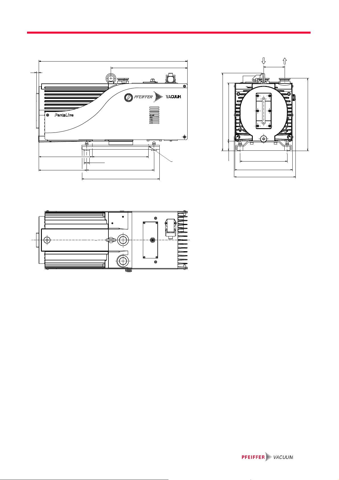
13.1 Dimensions
Ø
Ø
75
168
206
218
8
20
9
171
191
240
200
531
274
277
276
33
207
257
Technical data
29

Declaration of conformity
according to the EC directive:
• Machinery 2006/42/EC (Annex II, no. 1 A)
We hereby declare that the product cited below satisfies all relevant provisions of
EC directive "Machinery" 2006/42/EC.
In addition, the product cited below satisfies all relevant provisions of EC directive
"Electromagnetic Compatibility" 2004/108/EC .
The agent responsible for compiling the technical documentation is Mr. Sebastian
Oberbeck, Pfeiffer Vacuum GmbH, Berliner Straße 43, 35614 Aßlar.
Signatures:
PentaLine
®
Penta 10/20/35
Guidelines, harmonised standards and national standards and specifications
which have been applied:
DIN EN ISO 12100-1 : 2004 DIN EN 61010 : 2002 DIN EN 61000-6-3 : 2007
DIN EN ISO 12100-2 : 2004 DIN EN ISO 13857 : 2008 DIN EN 61000-6-4 : 20 07
DIN EN 1012-2 : 1996 DIN EN 61000-6-1 : 2007
DIN EN ISO 14121-1 : 20 07 DIN EN 61000-6-2 : 2006
Pfeiffer Vacuum GmbH
Berliner Straße 43
35614 Asslar
Germany
(M.Bender)
Managing Director
(Dr. M. Wiemer)
Managing Director
CE/2010

31

Pfeiffer Vacuum Technology AG · Headquarters/Germany
Tel. +49-(0) 64 41-8 02-0 · Fax +49-(0) 64 41-8 02-2 02 · info@pfeiffer-vacuum.de · www.pfeiffer-vacuum.net
Vacuum is nothing, but everything to us!
Turbopumps
Rotary vane pumps
Roots pumps
Dry compressing pumps
Leak detectors
Valves
Components and feedthroughs
Vacuum measurement
Gas analysis
System engineering
Service
 Loading...